EP4233641A2 - Möbelelement - Google Patents
Möbelelement Download PDFInfo
- Publication number
- EP4233641A2 EP4233641A2 EP23179587.3A EP23179587A EP4233641A2 EP 4233641 A2 EP4233641 A2 EP 4233641A2 EP 23179587 A EP23179587 A EP 23179587A EP 4233641 A2 EP4233641 A2 EP 4233641A2
- Authority
- EP
- European Patent Office
- Prior art keywords
- base plate
- table according
- running
- bearing
- furniture
- Prior art date
- Legal status (The legal status is an assumption and is not a legal conclusion. Google has not performed a legal analysis and makes no representation as to the accuracy of the status listed.)
- Granted
Links
Images


Classifications
-
- A—HUMAN NECESSITIES
- A47—FURNITURE; DOMESTIC ARTICLES OR APPLIANCES; COFFEE MILLS; SPICE MILLS; SUCTION CLEANERS IN GENERAL
- A47B—TABLES; DESKS; OFFICE FURNITURE; CABINETS; DRAWERS; GENERAL DETAILS OF FURNITURE
- A47B49/00—Revolving cabinets or racks; Cabinets or racks with revolving parts
- A47B49/004—Cabinets with compartments provided with trays revolving on a vertical axis
- A47B49/006—Corner cabinets
-
- A—HUMAN NECESSITIES
- A47—FURNITURE; DOMESTIC ARTICLES OR APPLIANCES; COFFEE MILLS; SPICE MILLS; SUCTION CLEANERS IN GENERAL
- A47B—TABLES; DESKS; OFFICE FURNITURE; CABINETS; DRAWERS; GENERAL DETAILS OF FURNITURE
- A47B17/00—Writing-tables
- A47B17/06—Writing-tables with parts, e.g. trays, movable on a pivot or by chains or belts
-
- A—HUMAN NECESSITIES
- A47—FURNITURE; DOMESTIC ARTICLES OR APPLIANCES; COFFEE MILLS; SPICE MILLS; SUCTION CLEANERS IN GENERAL
- A47B—TABLES; DESKS; OFFICE FURNITURE; CABINETS; DRAWERS; GENERAL DETAILS OF FURNITURE
- A47B17/00—Writing-tables
- A47B17/06—Writing-tables with parts, e.g. trays, movable on a pivot or by chains or belts
- A47B17/065—Pivotally mounted auxiliary tables
-
- A—HUMAN NECESSITIES
- A47—FURNITURE; DOMESTIC ARTICLES OR APPLIANCES; COFFEE MILLS; SPICE MILLS; SUCTION CLEANERS IN GENERAL
- A47B—TABLES; DESKS; OFFICE FURNITURE; CABINETS; DRAWERS; GENERAL DETAILS OF FURNITURE
- A47B49/00—Revolving cabinets or racks; Cabinets or racks with revolving parts
-
- A—HUMAN NECESSITIES
- A47—FURNITURE; DOMESTIC ARTICLES OR APPLIANCES; COFFEE MILLS; SPICE MILLS; SUCTION CLEANERS IN GENERAL
- A47B—TABLES; DESKS; OFFICE FURNITURE; CABINETS; DRAWERS; GENERAL DETAILS OF FURNITURE
- A47B49/00—Revolving cabinets or racks; Cabinets or racks with revolving parts
- A47B49/004—Cabinets with compartments provided with trays revolving on a vertical axis
-
- A—HUMAN NECESSITIES
- A47—FURNITURE; DOMESTIC ARTICLES OR APPLIANCES; COFFEE MILLS; SPICE MILLS; SUCTION CLEANERS IN GENERAL
- A47B—TABLES; DESKS; OFFICE FURNITURE; CABINETS; DRAWERS; GENERAL DETAILS OF FURNITURE
- A47B53/00—Cabinets or racks having several sections one behind the other
-
- A—HUMAN NECESSITIES
- A47—FURNITURE; DOMESTIC ARTICLES OR APPLIANCES; COFFEE MILLS; SPICE MILLS; SUCTION CLEANERS IN GENERAL
- A47B—TABLES; DESKS; OFFICE FURNITURE; CABINETS; DRAWERS; GENERAL DETAILS OF FURNITURE
- A47B77/00—Kitchen cabinets
- A47B77/02—General layout, e.g. relative arrangement of compartments, working surface or surfaces, supports for apparatus
- A47B77/022—Work tops
-
- A—HUMAN NECESSITIES
- A47—FURNITURE; DOMESTIC ARTICLES OR APPLIANCES; COFFEE MILLS; SPICE MILLS; SUCTION CLEANERS IN GENERAL
- A47B—TABLES; DESKS; OFFICE FURNITURE; CABINETS; DRAWERS; GENERAL DETAILS OF FURNITURE
- A47B77/00—Kitchen cabinets
- A47B77/04—Provision for particular uses of compartments or other parts ; Compartments moving up and down, revolving parts
- A47B77/10—Provision for particular uses of compartments or other parts ; Compartments moving up and down, revolving parts with members movable outwards to a position of use, e.g. tables, ironing boards
-
- A—HUMAN NECESSITIES
- A47—FURNITURE; DOMESTIC ARTICLES OR APPLIANCES; COFFEE MILLS; SPICE MILLS; SUCTION CLEANERS IN GENERAL
- A47B—TABLES; DESKS; OFFICE FURNITURE; CABINETS; DRAWERS; GENERAL DETAILS OF FURNITURE
- A47B85/00—Furniture convertible into other kinds of furniture
-
- A—HUMAN NECESSITIES
- A47—FURNITURE; DOMESTIC ARTICLES OR APPLIANCES; COFFEE MILLS; SPICE MILLS; SUCTION CLEANERS IN GENERAL
- A47B—TABLES; DESKS; OFFICE FURNITURE; CABINETS; DRAWERS; GENERAL DETAILS OF FURNITURE
- A47B9/00—Tables with tops of variable height
-
- A—HUMAN NECESSITIES
- A47—FURNITURE; DOMESTIC ARTICLES OR APPLIANCES; COFFEE MILLS; SPICE MILLS; SUCTION CLEANERS IN GENERAL
- A47B—TABLES; DESKS; OFFICE FURNITURE; CABINETS; DRAWERS; GENERAL DETAILS OF FURNITURE
- A47B9/00—Tables with tops of variable height
- A47B9/04—Tables with tops of variable height with vertical spindle
-
- A—HUMAN NECESSITIES
- A47—FURNITURE; DOMESTIC ARTICLES OR APPLIANCES; COFFEE MILLS; SPICE MILLS; SUCTION CLEANERS IN GENERAL
- A47B—TABLES; DESKS; OFFICE FURNITURE; CABINETS; DRAWERS; GENERAL DETAILS OF FURNITURE
- A47B9/00—Tables with tops of variable height
- A47B9/20—Telescopic guides
-
- A—HUMAN NECESSITIES
- A47—FURNITURE; DOMESTIC ARTICLES OR APPLIANCES; COFFEE MILLS; SPICE MILLS; SUCTION CLEANERS IN GENERAL
- A47B—TABLES; DESKS; OFFICE FURNITURE; CABINETS; DRAWERS; GENERAL DETAILS OF FURNITURE
- A47B2220/00—General furniture construction, e.g. fittings
- A47B2220/0061—Accessories
-
- A—HUMAN NECESSITIES
- A47—FURNITURE; DOMESTIC ARTICLES OR APPLIANCES; COFFEE MILLS; SPICE MILLS; SUCTION CLEANERS IN GENERAL
- A47B—TABLES; DESKS; OFFICE FURNITURE; CABINETS; DRAWERS; GENERAL DETAILS OF FURNITURE
- A47B81/00—Cabinets or racks specially adapted for other particular purposes, e.g. for storing guns or skis
- A47B81/002—Corner cabinets; Cabinets designed for being placed in a corner or a niche
-
- A—HUMAN NECESSITIES
- A47—FURNITURE; DOMESTIC ARTICLES OR APPLIANCES; COFFEE MILLS; SPICE MILLS; SUCTION CLEANERS IN GENERAL
- A47B—TABLES; DESKS; OFFICE FURNITURE; CABINETS; DRAWERS; GENERAL DETAILS OF FURNITURE
- A47B96/00—Details of cabinets, racks or shelf units not covered by a single one of groups A47B43/00 - A47B95/00; General details of furniture
- A47B96/02—Shelves
- A47B96/025—Shelves with moving elements, e.g. movable extensions or link elements
Definitions
- the present invention relates to a table, in particular a desk or kitchen work table, with a first body and a furniture element according to the preamble of claim 1.
- Furniture elements such as shelves or shelves, in which a support plate and a guided on this shelf is arranged at the same time rotationally and translationally movable shelf are, for example, from JP10318669 or the DE 10 2017 106 170 A1 known.
- the object of the present invention is to provide a table with a furniture element, consisting of at least one base plate and a body, which also ensures protection of the objects stored on or in the furniture element and good accessibility of the same.
- the furniture element is also to be further developed to enable a further improved support of a body of the furniture element on a base plate and to be able to rotate furniture elements positioned on an interfering contour such as a wall or in a corner.
- a body is a furniture component with a base and at least one closed side wall, behind which at least one storage element, for example a shelf, is arranged.
- the table has a furniture element with a base plate arranged on a body of the furniture element.
- the body of the furniture element can be moved relative to the base plate from a starting position into an intermediate position and further into an open position and back.
- the body In the intermediate position, the body is rotated in a rotational direction relative to the base plate and is displaced in a predetermined direction. In the starting position and in the open position, the body is congruent with the base plate, so it does not protrude beyond the dimensions of the base plate.
- one of the preferably two running grooves of the base plate can be designed as a running groove open towards an edge of the base plate.
- the at least one running groove of the base plate is formed in each case mirror-symmetrically with respect to an axis of symmetry running at an oblique angle to a side edge of the base plate.
- At least one running groove of the bearing plate can in each case be formed mirror-symmetrically to an axis of symmetry running at an oblique angle to a side edge of the bearing plate.
- the furniture element can be placed, for example, in a corner of the room consisting of two side walls that are at an angle to one another and can be rotated out of this corner in a simple manner, so that the furniture element is placed in a starting position, for example, in such a way that the furniture element is covered by the side walls of the body is and in a rotated, for example, by 90 ° or 180 °
- Opening position is rotated out of the corner that the at least one storage level of the furniture element is freely accessible by a user.
- a table with such a furniture element, standing against a room wall or in a room corner, can be moved from a closed position by side walls of the body of the furniture element into an open position with the same basic position by turning.
- Access to the contents of the furniture element or to the surface of the table is made possible in a simple manner by an at least partially combined translational-rotational movement of the furniture element.
- the proportions of translation and rotation in the overall movement can vary over the course of movement, depending on the design of the running grooves.
- the axis of symmetry runs at an angle of 45° to a side edge of the base plate and/or the bearing plate.
- a base of the body has a recess on its side facing the base plate, in which a bearing plate is fastened, in whose side facing the base plate at least one running groove is formed.
- the bearing plate can also be formed integrally with the bottom of the body.
- the running grooves formed in the bearing surface of the body are designed as closed, circumferential running grooves and thus enable reliable guidance of the rolling elements.
- the base plate, the bearing plate, the rolling elements and the rolling element cage preferably form a translation/rotation bearing.
- a translation/rotation bearing can be provided as a kit and can in particular also be subsequently integrated into the base of a furniture element.
- the rolling elements are accommodated captively in at least one rolling element cage, which in particular facilitates the assembly of the rolling elements between the running grooves.
- the running grooves formed in the bearing plate form at least one outer running groove and one inner running groove.
- a third running groove is formed between the outer running groove and the inner running groove.
- Such a third running groove serves to carry out additional functions such as in particular limiting the rotation of the furniture element.
- such a third running groove must also be formed in the base plate.
- a fixing device is provided on the body of the furniture element for the vertical fixing of the base plate.
- the base plate has a slot into which a guide sleeve protrudes, which protrudes from the underside of the base facing the base plate and thus guides the translational movement.
- a guide sleeve protrudes from the underside of the base facing the base plate and thus guides the translational movement.
- the furniture element is relative to the fixed furniture body using the translation-rotation bearing relative to the fixed furniture body from a position covering the body Furniture element in a position of the furniture element that does not completely cover the body and can be moved back.
- the furniture element in the open position, can be aligned perpendicular to the fixed furniture body.
- a first lifting device can additionally be attached to the body.
- the furniture element may have a second lifting device operable synchronously with the first lifting device, the translation-rotation bearing of the furniture element being mounted on the first lifting device.
- top, bottom, left, right, front, rear, etc. refer exclusively to the exemplary representation and position of the table, body, running grooves, base plate, rolling elements and the like selected in the respective figures. These terms are not to be understood as limiting, i.e. these references can change due to different working positions or the mirror-symmetrical design or the like.
- FIGS. 1 to 7 show an embodiment variant of a piece of furniture 10 according to the invention designed as a table with a furniture element 12 that can be moved in translation and rotation relative to a furniture body 11 that is fixed or frictionally engaged on a floor of a room.
- the furniture 10 is, as in particular in the figures 1 and 5 to 7 shown, designed as desk furniture or a kitchen island or kitchen work table or the like, with the furniture body 11 firmly set up on the floor of the room and the furniture element 12 that can be moved in translation and rotation relative to it.
- the furniture carcass 11 has a receptacle 112 in a central area of a work surface 111 which is used to accommodate a first lifting device 13 .
- the lifting device 13 embodied here as a telescopic lifting device is accommodated in the receptacle 112 of the furniture body 11 , telescopic elements 131 , 132 , 133 being able to be moved upwards out of the receptacle 112 .
- a support plate 134 is mounted on the uppermost of the telescopic elements 133 .
- a base plate 91 of an embodiment variant of a translation/rotation bearing 9 is attached to this support plate 134 .
- the furniture element 12 has, as exemplified in figure 2 is shown, a body 121 with a worktop, at the bottom of which the bearing plate 93 of the translation-rotation bearing 9 is attached.
- a side part 122 is arranged, in particular fastened, at one end of the body 121 and has a central receptacle for receiving a second lifting device 16 .
- the structure of the second lifting device 16 preferably corresponds to that of the first lifting device 13, ie it also has a first, a second and a third telescopic element 161, 162, 163.
- a foot 165 with at least two rolling elements 166 is arranged on the lowest, first telescopic element 161 of this lifting device 16 .
- the side part 122 thus serves as the second leg of the furniture element 12 for the lifting device 16 arranged on it.
- the furniture element 12 is thus supported on the one hand by the side part 122 and the second lifting device 16 arranged thereon and via the first lifting device 13 .
- the lifting device 13 supports the body 121 of the furniture element 12 via the translation/rotation bearing 9 accommodated between them.
- the furniture element 12 can thus be moved from an in figure 1 shown initial position, in which the furniture element 12 covers the furniture body 11, here completely, by synchronous actuation of the lifting devices 13, 16, with which the furniture element 12 can be raised relative to the furniture body 11, up to the in figure 5 shown open position are moved
- the upper side of the body 121 of the furniture element 12 serving as a work surface is aligned perpendicularly to the work surface 111 of the furniture body 11 .
- Other opening positions are also conceivable.
- the furniture element 12 can be moved through a larger or smaller angle, for example 180°.
- the arrangement of the translational-rotational bearing 9 on the support plate 134 of the first lifting device 13 makes it possible, when the furniture body 11 is standing in a corner of the room, to lift the furniture element 12 out of the in figure 1 position shown in the in figure 5 To move the position shown without the furniture element 12 protruding beyond a rear edge of the furniture body 11 during the movement. This is very advantageous when the furniture body 11 is arranged against a wall or in a corner.
- Translation-rotation bearing 9 shown is in detail in the Figures 3 and 4 shown.
- the base plate 91 also has running grooves 94 on its bearing surface facing the bearing plate 93 for guiding rolling elements 51 embodied here as balls.
- the rolling elements 51 are also accommodated in a rolling element cage 92 to prevent them from being lost.
- the rolling body cage 92 is circular here with a plurality of radially outwardly extending arms.
- a guide channel 97 is provided centrally and diagonally to two side edges of the base plate 91 aligned at right angles to one another.
- a guide carriage 151 is slidably mounted in this guide channel 97 .
- the guide carriage 151 as part of a fixing device 15 has on its upper side facing the bearing plate 93 or the body 121 of the furniture element 12 a bearing neck 152 which protrudes into an opening 99 in the bearing plate 93 and which is preferably formed on the upper side of the guide carriage 151.
- This bearing neck 152 serves as an axis for a bearing ring 157, in particular a ball bearing ring, which is inserted into the opening 99 of the bearing plate 93, which is preferably designed as a bore, and which enables a low-friction rotational movement of the bearing plate 93 relative to the guide carriage 151 and thus relative to the base plate 91.
- a roller bearing with at least two rollers 154 arranged one behind the other in the longitudinal direction of the guide channel 97 is arranged, in particular fastened, on the underside of the guide carriage 151 facing away from the bearing plate 93 .
- Each of these rollers 154 has a peripheral V-shaped groove 155 into which V-shaped webs 95 forming running surfaces for the rollers 154 protrude from opposite side walls of the guide channel 97 .
- a third groove 28c formed in an alternative embodiment in the base plate 21 and in the bearing plate 26 in addition to an outer groove 28a and an inner groove 28b.
- Such a third running groove 28c enables additional functions during the translational-rotational movement of the furniture element 2, 3.
- a third running groove 28c following a section of the outer running groove 28a radially to the origin of the rotational movement and lying radially further inwards is used here to limit the rotation of the furniture element.
- rolling element cage 5' which is shaped here approximately square with slightly radially inwardly bent sides, with recesses for rolling elements 51, which are arranged in the outer corners of the rolling element cage 5', for rolling elements 51, which can be moved in the outer running groove 28a are.
- rolling elements 51 are arranged on an outer circle K 1 .
- receptacles for further rolling elements 51 are formed, which can be moved in the inner running groove 28b.
- These rolling bodies 51 are arranged on an inner circle K 2 .
- the rolling element 51 which is to be guided in the third running groove 28c, is provided radially inwardly of one of the rolling elements 51 arranged in the corners of the rolling element cage 5'.
- This rolling element 51 is arranged on a central circle K 3 .
- the symmetry axes SK 1 of the rolling element arrangement 51 on the circle K 1 are inclined by 45° to the symmetry axes SK 2 of the rolling element arrangement 51 on the circle K 2 .
- inner running grooves 27a and outer running grooves 27b are also formed in the bearing plate 26, as well as a further third running groove 27c, which is also formed radially further inwards to the origin of rotation U relative to a section of one of the outer running grooves 27b.
- the running grooves 27a and 27b are shaped in such a way that they are arranged symmetrically both to a vertical axis of symmetry S 1 and to a horizontal axis of symmetry S 2 .
- figure 9 shows further embodiment variants for rolling element cages 5, 5′′ with rolling element seats which are arranged in such a way that they are arranged correspondingly on an outer circle K 1 and on an inner circle K 2 .
- FIG 3 a push to move mechanism shown in the form of an ejection element 14 that consists of an energy store 141 and a plunger 142 and is arranged in the guide channel 97 in order to eject the furniture element 12 after unlocking in a direction of movement.
- an ejection element 14 that consists of an energy store 141 and a plunger 142 and is arranged in the guide channel 97 in order to eject the furniture element 12 after unlocking in a direction of movement.
- the piece of furniture can also be in the form of desk furniture or a kitchen island or kitchen work table or the like, without an additional second lifting device on the furniture element 12.
- the furniture part that can be moved in translation and rotation is carried only by the first lifting device arranged on the stationary furniture body.
Landscapes
- Rolling Contact Bearings (AREA)
- Combinations Of Kitchen Furniture (AREA)
- Tables And Desks Characterized By Structural Shape (AREA)
- Assembled Shelves (AREA)
- Furniture Connections (AREA)
- Cabinets, Racks, Or The Like Of Rigid Construction (AREA)
Abstract
Description
- Die vorliegende Erfindung betrifft einen Tisch, insbesondere Schreibtisch oder Küchenarbeitstisch, mit einem ersten Korpus und einem Möbelelement gemäß dem Oberbegriff des Anspruchs 1.
- Möbelelemente wie Ablagen oder Regale, bei denen eine Tragplatte und eine auf dieser geführte gleichzeitig rotatorisch und translatorisch bewegbare Ablage angeordnet ist, sind beispielsweise aus der
JP 10318669 DE 10 2017 106 170 A1 bekannt. - Insbesondere die in der letztgenannten Veröffentlichung beschriebene Tragplatte hat sich in der Praxis an sich bewährt.
- Bei solchen Ablagen oder Regalen besteht häufig das Problem, die auf diesen gelagerten Gegenstände einerseits vor Schmutz zu schützen und andererseits eine gute Zugänglichkeit der Gegenstände zu ermöglichen. Darüberhinaus müssen diese Ablagen oder Regale stets beabstandet von Seitenwänden aufgestellt werden, um eine Drehung derselben zu ermöglichen, ohne an der Seitenwand anzustoßen.
- Aufgabe der vorliegenden Erfindung ist es, einen Tisch mit einem Möbelelement, bestehend aus mindestens einer Bodenplatte und einem Korpus, bereitzustellen, das gleichermaßen einen Schutz der Gegenstände, die auf oder in dem Möbelelement aufbewahrt sind, und eine gute Zugänglichkeit derselben gewährleistet.
- Das Möbelelement soll außerdem dahingehend weiterentwickelt werden, eine nochmals verbesserte Abstützung eines Korpus des Möbelelements auf einer Bodenplatte zu ermöglichen und Möbelelemente an einer Störkontur wie beispielsweise einer Wand oder in einer Ecke positioniert drehen zu können. Ein Korpus ist dabei eine Möbelkomponente mit einem Boden und mindestens einer geschlossenen Seitenwand, hinter der mindestens ein Ablageelement, beispielsweise ein Regalboden, angeordnet ist.
- Diese Aufgabe wird durch einen Tisch mit den Merkmalen des Anspruchs 1 gelöst.
- Der Tisch weist ein Möbelelement mit einer an einem Korpus des Möbelelements angeordneten Bodenplatte auf.
- Einander zugewandte Lagerflächen des Korpus und der Bodenplatte weisen jeweilige Laufrillen auf, in denen Wälzkörper geführt sind.
- Der Korpus des Möbelelements ist relativ zur Bodenplatte aus einer Ausgangsposition in eine Zwischenposition und weiter in eine Öffnungsposition und zurück bewegbar.
- In der Zwischenposition ist der Korpus relativ zur Bodenplatte in einer Drehrichtung gedreht und in einer vorbestimmten Richtung verschoben. In der Ausgangsposition und in der Öffnungsposition ist der Korpus deckungsgleich mit der Bodenplatte, steht also nicht über die Abmessungen der Bodenplatte über.
- Für den Fall, dass der Korpus in der Ausgangsposition die Bodenplatte in den Abmessungen überragt, oder andersherum, ist in der Öffnungsposition der gleiche Zustand (gleiche Ausrichtung / gleiche Überdeckung) wieder hergestellt, nur mit einem um 180° gedrehten Korpus.
- Bei mehr als einer Laufrille kann eine der vorzugsweise zwei Laufrillen der Bodenplatte als zu einem Rand der Bodenplatte hin offene Laufrille ausgebildet sein.
- Bei dem Möbelelement ist die mindestens eine Laufrille der Bodenplatte jeweils spiegelsymmetrisch zu einer schrägwinklig zu einer Seitenkante der Bodenplatte verlaufenden Symmetrieachse ausgebildet.
- Bei dem Möbelelement kann zusätzlich mindestens eine Laufrille der Lagerplatte jeweils spiegelsymmetrisch zu einer schrägwinklig zu einer Seitenkante der Lagerplatte verlaufenden Symmetrieachse ausgebildet sein.
- Bei einem solchen Tisch kann das Möbelelement dabei beispielsweise in einer von zwei winklig zueinander stehenden Seitenwänden bestehenden Raumecke abgestellt und in einfacher Weise aus dieser Raumecke herausgedreht werden, so dass das Möbelelement in einer Ausgangsposition beispielsweise so abgestellt ist, dass das Möbelelement durch Seitenwände des Korpus abgedeckt ist und in einer beispielsweise um 90° oder 180° gedrehten
- Öffnungsposition so aus der Ecke herausgedreht ist, dass die wenigstens eine Lagerebene des Möbelelements durch einen Benutzer frei zugänglich ist.
- Ein Tisch mit einem solche Möbelelement kann, an einer Raumwand oder in einer Raumecke stehend, bei gleicher Grundposition durch Drehen von einer durch Seitenwände des Korpus des Möbelelements geschlossenen Stellung in eine geöffnete Stellung verfahren werden.
- So wird durch eine zumindest teilweise kombinierte Translation-Rotationsbewegung des Möbelelements der Zugriff auf den Inhalt des Möbelelements bzw. auf die Oberfläche des Tischs in einfacher Weise ermöglicht. Dabei können die Anteile von Translation und Rotation an der Gesamtbewegung je nach Gestaltung der Laufrillen über den Bewegungsablauf variieren.
- Vorteilhafte Weiterbildungen der Erfindung sind Gegenstand der Unteransprüche.
- Gemäß einer vorteilhaften Ausführungsvariante des Tisches gemäß Anspruch 3 verläuft die Symmetrieachse in einem Winkel von 45° zu einer Seitenkante der Bodenplatte und/oder der Lagerplatte.
- Dies ermöglicht insbesondere eine Drehbewegung des Möbelelements um eine zur Ebene der Laufrillen senkrechte Achse aus einer rechtwinkligen Raumecke heraus, wobei das Möbelelement bei zumindest teilweise gleichzeitiger Translation eine Rotationsbewegung von 45° zu einer Seitenkante der Bodenplatte ausführt.
- Gemäß einer Ausführungsvariante weist ein Boden des Korpus auf seiner der Bodenplatte zugewandten Seite eine Ausnehmung auf, in der eine Lagerplatte befestigt ist, in deren der Bodenplatte zugewandten Seite wenigstens eine Laufrille angeformt ist. Alternativ kann die Lagerplatte auch integral mit dem Boden des Korpus ausgebildet sein.
- Die ermöglicht ein einfaches Anbringen und ggfs. Nachrüsten eines Möbelelements, das bisher ohne Translations-Rotationsmöglichkeit ausgestattet war, mit einer solchen Lagerplatte und den an diese angebundenen Bauteile zur Ermöglichung einer solchen Translations-Rotations-Bewegung.
- Gemäß einer weiteren Ausführungsvariante sind die in der Lagerfläche des Korpus eingeformten Laufrillen als geschlossene, umlaufende Laufrillen ausgebildet und ermöglichen so eine zuverlässige Führung der Wälzkörper.
- Bevorzugt bilden die Bodenplatte, die Lagerplatte, die Wälzkörper und der Wälzkörperkäfig ein Translations-Rotationslager. Ein solches Translations-Rotationslager ist als Bausatz bereitstellbar und kann insbesondere auch nachträglich in den Boden eines Möbelelements integriert werden.
- Gemäß einer weiteren Ausführungsvariante sind die Wälzkörper in wenigstens einem Wälzkörperkäfig verliersicher aufgenommen, was insbesondere die Montage der Wälzkörper zwischen den Laufrillen erleichtert.
- Gemäß einer bevorzugten Ausführungsvariante bilden die in der Lagerplatte angeformten Laufrillen wenigstens eine äußere Laufrille und eine innere Laufrille aus.
- Gemäß einer bevorzugten Weiterbildung ist zwischen der äußeren Laufrille und der inneren Laufrille eine dritte Laufrille angeformt. Eine solche dritte Laufrille dient dabei zur Ausübung zusätzlicher Funktionen wie insbesondere eine Drehbegrenzung des Möbelelements.In diesem Fall muss eine solche dritte Laufrille auch in der Bodenplatte ausgebildet sein.
- Zur vertikalen Fixierung der Bodenplatte ist gemäß einer weiteren Ausführungsvariante am Korpus des Möbelelements eine Fixiereinrichtung vorgesehen.
- Nach einer weiteren Ausführungsvariante weist die Bodenplatte einen Schlitz auf, in den eine Führungshülse vorsteht, die aus der der Bodenplatte zugewandten Unterseite des Bodens vorsteht und damit die Translationsbewegung führt. Insbesondere bei asymmetrischen Beladungen wird dadurch eine dauerhafte Verbindung zwischen Lagerplatte und Bodenplatte, und damit die Funktionalität des Lagers sichergestellt.
- Bei dem erfindungsgemäßen Tisch, insbesondere Schreibtisch oder auch Küchenarbeitstisch ist das Möbelelement relativ zum fest stehenden Möbelkorpus mithilfe des Translations-Rotationslagers relativ zum fest stehenden Möbelkorpus aus einer den Korpus überdeckenden Position des Möbelelements in eine den Korpus nicht vollständig überdeckende Position des Möbelelementes und zurück bewegbar.
- Beispielsweise kann in der Öffnungsposition das Möbelelement zum fest stehenden Möbelkorpus senkrecht ausgerichtet sein. An dem Korpus kann zusätzlich eine erste Anhebeeineinrichtung befestigt sein.
- In diesem Fall kann das Möbelelement eine mit der ersten Anhebeeineinrichtung synchron betätigbare zweite Anhebeeineinrichtung aufweisen, wobei das Translations-Rotationslager des Möbelelements auf der ersten Anhebeeineinrichtung montiert ist.
- Nachfolgend werden bevorzugte Ausführungsvarianten anhand der beiliegenden Zeichnungen näher erläutert. Es zeigen:
- Fig. 1-7
- schematische Ansichten einer Ausführungsvariante eines erfindungsgemäßen Tisches, der relativ zu einem Möbelkorpus translatorisch und rotatorisch bewegbar ist,
- Fig.8-9
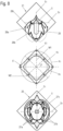
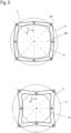
- Draufsichten auf alternative Ausführungsvarianten einer Laufrillengestaltung und entsprechend angepasster Wälzkörperkäfige.
- In der nachfolgenden Figurenbeschreibung beziehen sich Begriffe wie oben, unten, links, rechts, vorne, hinten usw. ausschließlich auf die in den jeweiligen Figuren gewählte beispielhafte Darstellung und Position des Tisches, Korpus, der Laufrillen, der Bodenplatte, der Wälzkörper und dergleichen. Diese Begriffe sind nicht einschränkend zu verstehen, d.h., durch verschiedene Arbeitsstellungen oder die spiegelsymmetrische Auslegung oder dergleichen können sich diese Bezüge ändern.
- In den
Fig. 1 bis 7 ist mit dem Bezugszeichen 10 eine als Tisch ausgeführte Ausführungsvariante eines Möbels 10 mit Möbelelement bezeichnet. - Die
Figuren 1 bis 7 zeigen eine Ausführungsvariante eines erfindungsgemäßen als Tisch ausgebildeten Möbels 10 mit einem Möbelelement 12, das translatorisch und rotatorisch relativ zu einem fest bzw. reibschlüssig auf einem Fußboden eines Raumes stehenden Möbelkorpus 11 bewegbar ist. - Das Möbel 10 ist, wie insbesondere in den
Figuren 1 und5 bis 7 dargestellt ist, als Schreibtischmöbel oder Kücheninsel oder Küchenarbeitstisch oder dergleichen ausgebildet, mit dem fest auf dem Raumboden aufgestellten Möbelkorpus 11 und dem relativ zu diesem translatorisch und rotatorisch bewegbaren Möbelelement 12. - Wie in den
Figuren 2 ,6 und7 gezeigt ist, weist der Möbelkorpus 11 in einem zentralen Bereich einer Arbeitsfläche 111 eine Aufnahme 112 auf, die der Unterbringung einer ersten Anhebeeinrichtung 13 dient. - Die hier als Teleskophubeinrichtung ausgebildete Anhebeeinrichtung 13 ist in der Aufnahme 112 des Möbelkorpus 11 aufgenommen, wobei Teleskopelemente 131, 132, 133 aus der Aufnahme 112 heraus nach oben verfahrbar sind.
- Auf dem obersten der Teleskopelemente 133 ist eine Tragplatte 134 montiert. Auf dieser Tragplatte 134 ist eine Bodenplatte 91 einer Ausführungsvariante eines Translations-Rotationslagers 9 befestigt.
- Das Möbelelement 12 weist, wie beispielhaft in
Figur 2 dargestellt ist, einen Korpus 121 mit einer Arbeitsplatte auf, an deren Boden die Lagerplatte 93 des Translations-Rotationslagers 9 befestigt ist. - An einem Ende des Korpus 121 ist ein Seitenteil 122 angeordnet, insbesondere befestigt, welches eine zentrale Aufnahme zur Aufnahme einer zweiten Anhebeeinrichtung 16 aufweist.
- Die zweite Anhebeeinrichtung 16 entspricht dabei in ihrem Aufbau bevorzugt dem der ersten Anhebeeinrichtung 13, also weist auch ein erstes, ein zweites und ein drittes Teleskopelement 161, 162, 163 auf.
- Am untersten, ersten Teleskopelement 161 dieser Anhebeeinrichtung 16 ist ein Fuß 165 mit wenigstens zwei Rollelementen 166 angeordnet.
- Das Seitenteil 122 dient somit der daran angeordneten Anhebeeinrichtung 16 als zweites Standbein des Möbelelements 12.
- Das Möbelelement 12 wird dadurch einerseits von dem das Seitenteil 122 und die daran angeordnete zweite Anhebeeinrichtung 16 sowie über die erste Anhebeeinrichtung 13 getragen.
- Die Anhebeeinrichtung 13 stützt dabei den Korpus 121 des Möbelelements 12 über das dazwischen aufgenommene Translations-Rotationslager 9.
- Das Möbelelement 12 kann so von einer in
Figur 1 gezeigten Ausgangsstellung, bei der das Möbelelement 12 den Möbelkorpus 11, hier vollständig, überdeckt, durch synchrones Betätigen der Anhebeeinrichtungen 13, 16, mit der das Möbelelement 12 relativ zum Möbelkorpus 11 anhebbar ist, bis in die inFigur 5 gezeigte Öffnungsstellung bewegt werden - In der Öffnungsstellung ist die hier als Arbeitsfläche dienende Oberseite des Korpus 121 des Möbelelements 12 senkrecht zur Arbeitsfläche 111 des Möbelkorpus 11 ausgerichtet. Denkbar sind auch andere Öffnungsstellungen. Je nach Ausrichtung und Ausführung des Translations-Rotationslagers 9 kann das Möbelelement 12 um einen größeren oder kleineren Winkel, beispielsweise 180°, bewegt werden.
- Durch die Anordnung des Translations-Rotationslagers 9 auf der Tragplatte 134 der ersten Anhebeeinrichtung 13 ist es ermöglicht, bei in einer Raumecke stehenden Möbelkorpus 11 das Möbelelement 12 aus der in
Figur 1 gezeigten Position in die inFigur 5 gezeigte Position zu bewegen, ohne dass das Möbelelement 12 über eine hintere Kante des Möbelkorpus 11 während der Bewegung übersteht. Dieses ist sehr vorteilhaft, wenn der Möbelkorpus 11 an einer Wand oder in einer Ecke angeordnet ist. - Das in
Figur 2 gezeigte Translations-Rotationslager 9 ist im Detail in denFiguren 3 und4 dargestellt. - Wie in den
Figuren 3 und4 dargestellt ist, weist die Bodenplatte 91 auf ihrer der Lagerplatte 93 zugewandten Lagerfläche ebenfalls Laufrillen 94 zur Führung von hier als Kugeln ausgebildeten Wälzkörpern 51 auf. - Die Wälzkörper 51 sind ebenfalls in einem Wälzkörperkäfig 92 zur Verliersicherung aufgenommen. Der Wälzkörperkäfig 92 ist hier kreisförmig mit mehreren sich radial nach außen erstreckenden Armen ausgebildet.
- Zentral und diagonal zu zwei rechtwinklig zueinander ausgerichteten Seitenkanten der Bodenplatte 91 ist auch hier ein Führungskanal 97 vorgesehen.
- In diesem Führungskanal 97 ist ein Führungsschlitten 151 verschiebbar gelagert.
- Der Führungsschlitten 151 als Teil einer Fixiereinrichtung 15 weist auf seiner der Lagerplatte 93 bzw. dem Korpus 121 des Möbelelements 12 zugewandten Oberseite ein in eine Öffnung 99 in der Lagerplatte 93 vorstehenden Lagerhals 152 auf, der bevorzugt an der Oberseite des Führungsschlittens 151 angeformt ist.
- Dieser Lagerhals 152 dient als Achse für einen in die bevorzugt als Bohrung ausgebildeten Öffnung 99 der Lagerplatte 93 eingesetzten Lagerring 157, insbesondere eines Kugellagerrings, durch den eine reibungsarme Rotationsbewegung der Lagerplatte 93 relativ zum Führungsschlitten 151 und damit relativ zur Bodenplatte 91 ermöglicht ist.
- Auf der der Lagerplatte 93 abgewandten Unterseite des Führungsschlittens 151 ist ein Rollenlager mit wenigstens zwei in Längsrichtung des Führungskanals 97 hintereinander angeordneten Laufrollen 154 angeordnet, insbesondere befestigt.
- Jede dieser Laufrollen 154 weist eine umfängliche v-förmige Nut 155 auf, in die aus gegenüberliegenden Seitenwänden des Führungskanals 97 vorstehende v-förmige, Laufflächen für die Laufrollen 154 bildende Stege 95 vorstehen.
- Durch die v-förmigen Nuten 155 der Laufrollen 154, die entlang der v-förmigen Stege 95 im Führungskanal 97 geführt sind, ergibt sich ein äußerst stabiler und gleichbleibender Ablauf der Translations-Rotations-Bewegung des Möbelelements 12.
- Wie in
Figur 8 dargestellt, ist in einer alternativen Ausführungsvariante in der Bodenplatte 21 und in der Lagerplatte 26 neben einer äußeren Laufrille 28a und einer inneren Laufrille 28b eine dritte Laufrille 28c angeformt. - Eine solche dritte Laufrille 28c ermöglicht weitere Funktionen bei der Translation-Rotationsbewegung des Möbelelements 2, 3.
- Die in
Figur 8 einem Teilstück der äußeren Laufrille 28a radial zum Ursprung der Rotationsbewegung radial weiter innen liegend folgende dritte Laufrille 28c dient hier der Rotationsbegrenzung des Möbelelements. - Um dies zu ermöglichen, ist der in der mittleren der drei Darstellungen in
Figur 8 gezeigte Wälzkörperkäfig 5', der hier in etwa quadratisch mit leicht radial nach innen durchgebogenen Seiten geformt ist, mit Ausnehmungen für Wälzkörper 51 ausgebildet, die in den äußeren Ecken des Wälzkörperkäfigs 5' angeordnet sind, für Wälzkörper 51, die in der äußeren Laufrille 28a verfahrbar sind. Diese Wälzkörper 51 sind auf einem äußeren Kreis K1 angeordnet. - Etwa zentral in den Seiten des Wälzkörperkäfigs 5' sind Aufnahmen für weitere Wälzkörper 51 angeformt, die in der inneren Laufrille 28b verfahrbar sind. Diese Wälzkörper 51 sind auf einem inneren Kreis K2 angeordnet.
- Der Wälzkörper 51, der in der dritten Laufrille 28c geführt werden soll, ist radial innen zu einem der in den Ecken des Wälzkörperkäfigs 5' angeordneten Wälzkörpern 51 vorgesehen. Dieser Wälzkörper 51 ist auf einem mittleren Kreis K3 angeordnet.
- Die Symmetrieachsen SK1 der Wälzkörperanordnung 51 auf dem Kreis K1 sind um 45° geneigt zu den Symmetrieachsen SK2 der Wälzkörperanordnung 51 auf dem Kreis K2.
- Wie in der unteren Abbildung der
Figur 8 zu erkennen ist, sind auch in der Lagerplatte 26 innere Laufrillen 27a und äußere Laufrillen 27b angeformt sowie eine weitere dritte Laufrille 27c, die ebenfalls relativ zu einem Teilstück einer der äußeren Laufrillen 27b radial weiter innen zum Rotationsursprung U angeformt ist. - Wie in dieser Abbildung des Weiteren zu erkennen ist, sind die Laufrillen 27a und 27b so geformt, dass sie sowohl zu einer hier vertikalen Symmetrieachse S1 als auch zu einer horizontalen Symmetrieachse S2 symmetrisch angeordnet sind.
-
Figur 9 zeigt weitere Ausführungsvarianten für Wälzkörperkäfige 5, 5" mit Wälzkörperaufnahmen, die so angeordnet sind, dass sie entsprechend auf einem äußeren Kreis K1 und auf einem inneren Kreis K2 angeordnet sind. - Zusätzlich ist in
Figur 3 eine Push to move- Mechanik in Gestalt eines Ausstosselements 14 gezeigt, dass aus einem Kraftspeicher 141 und einem Stößel 142 besteht und im Führungskanal 97 angeordnet ist, um das Möbelelement 12 nach Entriegelung in eine Bewegungsrichtung auszustoßen. - Durch den Einsatz einer solchen Push to move- Mechanik ist insbesondere ermöglicht, dass Möbelelement ohne Betätigungsgriff auszubilden und durch Eindrücken entgegen der beabsichtigten Öffnungsrichtung die Öffnungsbewegung des Möbelelements einzuleiten. Auch der Einsatz einer in anderer Weise aktivierbaren Ausstoßmechanik ist denkbar.
- Alternativ kann das Möbel auch als Schreibtischmöbel oder Kücheninsel oder Küchenarbeitstisch oder dergleichen ausgebildet sein, ohne zusätzliche zweite Anhebeeinrichtung am Möbelelement 12. Das translatorisch-rotatorisch bewegbare Möbelteil wird in diesem Fall nur über die am ortsfesten Möbelkorpus angeordnete erste Anhebeeinrichtung getragen.
-
- 9
- Translations-Rotationslager, Lager
- 91
- Bodenplatte
- 92
- Wälzkörperkäfig
- 93
- Lagerplatte
- 94
- Laufrille
- 95
- Steg
- 97
- Führungskanal
- 99
- Öffnung
- 10
- Möbel
- 11
- Möbelkorpus
- 111
- Arbeitsfläche
- 112
- Aufnahme
- 12
- Möbelelement
- 121
- Korpus
- 122
- Seitenteil
- 13
- Anhebeeineinrichtung
- 131
- erstes Teleskopelement
- 132
- zweites Teleskopelement
- 133
- drittes Teleskopelement
- 134
- Tragplatte
- 14
- Ausstoßelement
- 141
- Kraftspeicher
- 142
- Stößel
- 15
- Fixiereinrichtung
- 151
- Führungsschlitten
- 152
- Lagerhals
- 154
- Laufrolle
- 155
- Nut
- 157
- Lagerring
- 16
- zweite Anhebeeineinrichtung
- 161
- erstes Teleskopelement
- 162
- zweites Teleskopelement
- 163
- drittes Teleskopelement
- 165
- Fuß
- 166
- Rollelement
- A
- Richtung
- K1, K2, K3
- Kreis
- R1, R2
- Drehrichtung
- S1, S2
- Symmetrieachse
- SK1, SK2
- Symmetrieachse
- U
- Rotationsursprung
Claims (14)
- Tisch, insbesondere Schreibtisch oder Küchenarbeitstisch, mit einem ersten Korpus (11) und einem Möbelelement (12), wobei das Möbelelement (12) aufweist- einen Korpus (121) und eine Bodenplatte (91),- wobei einander zugewandte Lagerflächen des Korpus (121) und der Bodenplatte (91) jeweils mindestens eine Laufrille (94) aufweisen, in denen Wälzkörper (51) geführt sind,- wobei der Korpus (121) relativ zur Bodenplatte (91) aus einer Ausgangsposition in eine Zwischenposition und weiter in eine Öffnungsposition und zurück bewegbar ist,- wobei in der Zwischenposition der Korpus (121) relativ zur Bodenplatte (91) in einer Drehrichtung (R1, R2) gedreht und in einer vorbestimmten Richtung (A) verschoben ist,
dadurch gekennzeichnet, dass- die mindestens eine Laufrille (94) der Bodenplatte (91) spiegelsymmetrisch zu einer schrägwinklig zu einer Seitenkante der Bodenplatte (91) verlaufenden Symmetrieachse ausgebildet ist. - Tisch nach Anspruch 1, dadurch gekennzeichnet, dass der Korpus (121) auf seiner der Bodenplatte (91) zugewandten Seite eine Lagerplatte (93) aufweist, wobei in der der Bodenplatte (91) zugewandten Seite der Lagerplatte (93) wenigstens eine Laufrille (65) angeformt ist und die mindestens eine Laufrille (65) der Lagerplatte (93) spiegelsymmetrisch zu einer schrägwinklig zu einer Seitenkante der Lagerplatte (93) verlaufenden Symmetrieachse ausgebildet ist.
- Tisch nach Anspruch 1 oder 2, dadurch gekennzeichnet, dass die Symmetrieachse um einen Winkel von 45° zu einer Seitenkante der Bodenplatte (91) und/oder der Lagerplatte (93) verläuft.
- Tisch nach einem der vorstehenden Ansprüche, dadurch gekennzeichnet, dass wenigstens eine der Laufrillen (94) der Bodenplatte (91) als zu einem Rand der Bodenplatte (91) hin offene Laufrille (94) ausgebildet ist.
- Tisch nach einem der vorstehenden Ansprüche, dadurch gekennzeichnet, dass wenigstens eine der in der Lagerplatte (93) angeformten Laufrillen (65) als geschlossene, umlaufende Laufrille ausgebildet ist.
- Tisch nach einem der Ansprüche 2 bis 5, dadurch gekennzeichnet, dass die Bodenplatte (91), die Lagerplatte (93), die Wälzkörper (51) und ein Wälzkörperkäfig (92), in dem die Wälzkörper (51), vorzugsweise verliergesichert, aufgenommen sind, ein Translations-Rotationslager (9) bilden.
- Tisch nach einem der vorstehenden Ansprüche, dadurch gekennzeichnet, dass mehrere der Wälzkörper (51) kreisförmig oder rechteckförmig im Wälzkörperkäfig (92) angeordnet sind.
- Tisch nach Anspruch 7, dadurch gekennzeichnet, dass die Wälzkörper (51) auf mindestens zwei Kreisen (K1, K2) angeordnet sind, wobei die Symmetrieachsen (SK1) der Wälzkörperanordnung (51) auf dem Kreis (K1) um 45° geneigt zu den Symmetrieachsen (SK2) der Wälzkörperanordnung (51) auf dem Kreis (K2) sind.
- Tisch nach Anspruch 8, dadurch gekennzeichnet, dass wenigstens zwei Wälzkörper (51) radial zu einem Rotationsursprung hintereinander im Wälzkörperkäfig (92) angeordnet sind.
- Tisch nach einem der vorstehenden Ansprüche, dadurch gekennzeichnet, dass die in der Lagerplatte (93) angeformten Laufrillen (65) wenigstens eine äußere Laufrille und eine innere Laufrille ausbilden.
- Tisch nach Anspruch 10, dadurch gekennzeichnet, dass zwischen der äußeren Laufrille und der inneren Laufrille eine dritte Laufrille angeformt ist.
- Tisch nach einem der vorstehenden Ansprüche 2 bis 11, dadurch gekennzeichnet, dass zur vertikalen Fixierung der Bodenplatte (91) am Korpus (121) des Möbelelements (12) oder der an diesem befestigten Lagerplatte (93) eine Fixiereinrichtung (7) vorgesehen ist.
- Tisch nach einem der vorstehenden Ansprüche, dadurch gekennzeichnet, dass der erste Korpus (11) als reibschlüssig auf einem Boden ortsfest abstellbarer Korpus mit einer an diesem angeordneten ersten Anhebeeineinrichtung (13) ausgebildet ist, wobei das Translations-Rotationslager (9) des Möbelelements (12) auf der ersten Anhebeeineinrichtung (13) montiert ist.
- Tisch nach Anspruch 13, dadurch gekennzeichnet, dass der erste Korpus (11) als reibschlüssig auf einem Boden ortsfest abstellbarer Korpus mit einer an diesem angeordneten ersten Anhebeeineinrichtung (13) ausgebildet ist und das Möbelelement (12) eine mit der ersten Anhebeeineinrichtung (13) synchron betätigbare zweite Anhebeeineinrichtung (16) aufweist, wobei das Translations-Rotationslager (9) des Möbelelements (12) auf der ersten Anhebeeineinrichtung (13) montiert ist.
Applications Claiming Priority (3)
| Application Number | Priority Date | Filing Date | Title |
|---|---|---|---|
| DE102019109866.1A DE102019109866A1 (de) | 2019-04-15 | 2019-04-15 | Möbelelement |
| PCT/EP2020/060509 WO2020212373A1 (de) | 2019-04-15 | 2020-04-15 | Möbelelement |
| EP20720392.8A EP3955771B1 (de) | 2019-04-15 | 2020-04-15 | Möbelelement |
Related Parent Applications (2)
| Application Number | Title | Priority Date | Filing Date |
|---|---|---|---|
| EP20720392.8A Division EP3955771B1 (de) | 2019-04-15 | 2020-04-15 | Möbelelement |
| EP20720392.8A Division-Into EP3955771B1 (de) | 2019-04-15 | 2020-04-15 | Möbelelement |
Publications (3)
| Publication Number | Publication Date |
|---|---|
| EP4233641A2 true EP4233641A2 (de) | 2023-08-30 |
| EP4233641A3 EP4233641A3 (de) | 2023-10-25 |
| EP4233641B1 EP4233641B1 (de) | 2025-07-09 |
Family
ID=70333933
Family Applications (2)
| Application Number | Title | Priority Date | Filing Date |
|---|---|---|---|
| EP20720392.8A Active EP3955771B1 (de) | 2019-04-15 | 2020-04-15 | Möbelelement |
| EP23179587.3A Active EP4233641B1 (de) | 2019-04-15 | 2020-04-15 | Tisch |
Family Applications Before (1)
| Application Number | Title | Priority Date | Filing Date |
|---|---|---|---|
| EP20720392.8A Active EP3955771B1 (de) | 2019-04-15 | 2020-04-15 | Möbelelement |
Country Status (9)
| Country | Link |
|---|---|
| US (2) | US11839297B2 (de) |
| EP (2) | EP3955771B1 (de) |
| JP (2) | JP7527299B2 (de) |
| KR (2) | KR102843531B1 (de) |
| CN (2) | CN113453583B (de) |
| DE (1) | DE102019109866A1 (de) |
| ES (2) | ES2964835T3 (de) |
| PL (1) | PL4233641T3 (de) |
| WO (1) | WO2020212373A1 (de) |
Families Citing this family (44)
| Publication number | Priority date | Publication date | Assignee | Title |
|---|---|---|---|---|
| DE102019109868A1 (de) * | 2019-04-15 | 2020-10-29 | Paul Hettich Gmbh & Co. Kg | Bodenelement |
| DE102019109866A1 (de) * | 2019-04-15 | 2020-10-15 | Paul Hettich Gmbh & Co. Kg | Möbelelement |
| DE102019113251A1 (de) * | 2019-05-20 | 2020-11-26 | Paul Hettich Gmbh & Co. Kg | Möbelelement |
| DE102020124883A1 (de) | 2020-09-24 | 2022-03-24 | Nobilia-Werke J. Stickling GmbH & Co. KG | Möbeleckelement |
| DE102021101535A1 (de) * | 2021-01-25 | 2022-07-28 | Paul Hettich Gmbh & Co. Kg | Möbelelement |
| DE102021110323A1 (de) | 2021-01-25 | 2022-07-28 | Paul Hettich Gmbh & Co. Kg | Möbelelement und Möbel |
| DE102021101537A1 (de) | 2021-01-25 | 2022-07-28 | Paul Hettich Gmbh & Co. Kg | Drehbares Möbelelement und Möbel |
| PL4280911T3 (pl) | 2021-01-25 | 2025-03-31 | Paul Hettich Gmbh & Co. Kg | Element meblowy i mebel |
| DE102021110322A1 (de) | 2021-01-25 | 2022-07-28 | Paul Hettich Gmbh & Co. Kg | Möbelelement und Möbel |
| DE102021128965A1 (de) | 2021-11-08 | 2023-05-11 | Paul Hettich Gmbh & Co. Kg | Möbelelement |
| DE102021131826A1 (de) | 2021-12-02 | 2023-06-07 | Paul Hettich Gmbh & Co. Kg | Vorrichtung zur rotatorischen und translatorischen Bewegung |
| DE102021131827A1 (de) | 2021-12-02 | 2023-06-07 | Paul Hettich Gmbh & Co. Kg | Möbel oder Haushaltsgerät |
| DE102021133993A1 (de) | 2021-12-21 | 2023-06-22 | Paul Hettich Gmbh & Co. Kg | Möbel und Verfahren zur Positionierung eines Drehelements in einem Möbelkorpus eines Möbels |
| DE102021133995A1 (de) | 2021-12-21 | 2023-06-22 | Paul Hettich Gmbh & Co. Kg | Drehelement, Möbel und Verfahren zur Positionierung eines Translations-Rotations-Beschlags eines Drehelements |
| WO2023154932A1 (en) * | 2022-02-14 | 2023-08-17 | Kovhr Inc. | Organizational shell |
| DE102022105121A1 (de) | 2022-03-04 | 2023-09-07 | Paul Hettich Gmbh & Co. Kg | Möbel- oder Haushaltsgeräteelement |
| DE202022003155U1 (de) | 2022-03-04 | 2025-02-12 | Paul Hettich Gmbh & Co. Kg | Möbel- oder Haushaltsgeräteelement |
| DE102022105122A1 (de) | 2022-03-04 | 2023-09-07 | Paul Hettich Gmbh & Co. Kg | Möbel- oder Haushaltsgeräteelement |
| DE202022003159U1 (de) | 2022-03-08 | 2025-02-13 | Paul Hettich Gmbh & Co. Kg | Anordnung eines Trägerelements und einer Ablage |
| DE102022105416A1 (de) | 2022-03-08 | 2023-09-14 | Paul Hettich Gmbh & Co. Kg | Führungslager und Möbelelement |
| DE102022105414A1 (de) | 2022-03-08 | 2023-09-14 | Paul Hettich Gmbh & Co. Kg | Anordnung eines Trägerelements und einer Ablage |
| DE202022003158U1 (de) | 2022-03-08 | 2025-02-13 | Paul Hettich Gmbh & Co. Kg | Führungslager und Möbelelement |
| EP4496498B1 (de) * | 2022-03-23 | 2026-02-04 | Paul Hettich GmbH & Co. KG | Anordnung eines aus wenigstens zwei möbeln oder haushaltsgeräten bestehenden modularen innenausstattungssystems für räume auf wenigstens einer plattform |
| DE202022003160U1 (de) | 2022-04-27 | 2025-02-14 | Paul Hettich Gmbh & Co. Kg | Führungsbeschlag und Möbel- oder Haushaltsgeräteelement |
| DE202022003154U1 (de) | 2022-04-27 | 2025-02-12 | Paul Hettich Gmbh & Co. Kg | Führungsbeschlag und Möbel- oder Haushaltsgeräteelement |
| DE102022110204A1 (de) | 2022-04-27 | 2023-11-02 | Paul Hettich Gmbh & Co. Kg | Führungsbeschlag und Möbel- oder Haushaltsgeräteelement |
| DE102022110207A1 (de) * | 2022-04-27 | 2023-11-02 | Paul Hettich Gmbh & Co. Kg | Führungsbeschlag und Möbel- oder Haushaltsgeräteelement |
| DE102022111532A1 (de) | 2022-05-09 | 2023-11-09 | Druck- und Spritzgußwerk Hettich GmbH & Co. KG | Ausstoßvorrichtung |
| DE102022111534A1 (de) | 2022-05-09 | 2023-11-09 | Paul Hettich Gmbh & Co. Kg | Ausstossvorrichtung |
| DE102022124143A1 (de) | 2022-09-20 | 2024-03-21 | Paul Hettich Gmbh & Co. Kg | Translations-Rotations-Beschlag und Möbel- oder Haushaltsgeräteelement |
| DE102022124145A1 (de) | 2022-09-20 | 2024-03-21 | Paul Hettich Gmbh & Co. Kg | Translations-Rotations-Beschlag und Möbel- oder Haushaltsgeräteelement |
| DE202022003161U1 (de) | 2022-09-20 | 2025-02-14 | Paul Hettich Gmbh & Co. Kg | Translations-Rotations-Beschlag und Möbel- oder Haushaltsgeräteelement |
| DE202022003162U1 (de) | 2022-09-20 | 2025-02-14 | Paul Hettich Gmbh & Co. Kg | Translations-Rotations-Beschlag und Möbel- oder Haushaltsgeräteelement |
| DE102022125329A1 (de) | 2022-09-30 | 2024-04-04 | Paul Hettich Gmbh & Co. Kg | Möbel- oder Haushaltsgeräteelement |
| DE102023119311A1 (de) | 2022-10-25 | 2024-04-25 | Paul Hettich Gmbh & Co. Kg | Translations-Rotations-Anordnung und Möbel- oder Haushaltsgeräteelement |
| CN120282732A (zh) | 2022-10-25 | 2025-07-08 | 保罗海蒂诗有限及两合公司 | 平移旋转装置和家具或家用电器元件 |
| DE102023100625A1 (de) | 2023-01-12 | 2024-07-18 | Paul Hettich Gmbh & Co. Kg | Möbel- oder Haushaltsgeräteelement und Verfahren zur Montage eines Möbel- oder Haushaltsgeräteelements |
| DE102023105700A1 (de) | 2023-03-08 | 2024-09-12 | Paul Hettich Gmbh & Co. Kg | Translations-Rotations-Beschlag und Möbel- oder Haushaltsgeräteelement |
| CN219720169U (zh) * | 2023-03-08 | 2023-09-22 | 宁波诺室设计有限公司 | 移轴式置物装置 |
| DE102023107074A1 (de) | 2023-03-21 | 2024-09-26 | Paul Hettich Gmbh & Co. Kg | Translations-Rotations-Anordnung für wenigstens ein Möbel oder Haushaltsgerät |
| CN219982592U (zh) * | 2023-05-19 | 2023-11-10 | 深圳市艾文家庭用品有限公司 | 首饰展示架 |
| DE102023117142A1 (de) | 2023-06-29 | 2025-01-02 | Paul Hettich Gmbh & Co. Kg | Translations-Rotations-Beschlag und Möbel- oder Haushaltsgeräteelement |
| CN117100066B (zh) * | 2023-08-08 | 2026-04-03 | 广东炬森精密科技股份有限公司 | 一种电驱动隐藏式转角柜的连接器 |
| DE102024101349A1 (de) * | 2024-01-17 | 2025-07-17 | Paul Hettich Gmbh & Co. Kg | Möbelelement |
Citations (2)
| Publication number | Priority date | Publication date | Assignee | Title |
|---|---|---|---|---|
| JPH10318669A (ja) | 1997-03-22 | 1998-12-04 | Samsung Electron Co Ltd | 冷蔵庫用回転形棚 |
| DE102017106170A1 (de) | 2017-03-22 | 2018-09-27 | Paul Hettich Gmbh & Co. Kg | Vorrichtung zur rotatorischen und translatorischen Bewegung eines Gegenstands |
Family Cites Families (32)
| Publication number | Priority date | Publication date | Assignee | Title |
|---|---|---|---|---|
| US535886A (en) * | 1895-03-19 | Base for reversible folding beds | ||
| US330409A (en) * | 1885-11-17 | Laes laeson | ||
| GB412648A (en) * | 1933-01-13 | 1934-07-05 | William Angus & Company Ltd | Improvements in sideboards, cabinets, wardrobes, desks and like furniture |
| US2650871A (en) * | 1949-05-05 | 1953-09-01 | Holderegger Hermann | Furniture provided with drawers |
| US2988413A (en) * | 1960-03-31 | 1961-06-13 | A A Laun Furniture Co | Combination furniture piece |
| JPS488886Y1 (de) * | 1970-04-27 | 1973-03-08 | ||
| US4124262A (en) * | 1978-04-28 | 1978-11-07 | Keystone Consolidated Industries, Inc. | Hardware for pivoting cabinet shelf |
| DE2944551A1 (de) * | 1979-11-05 | 1981-05-14 | Günter 6096 Raunheim Hack | Kombinationsmoebel |
| US4959582A (en) * | 1986-08-28 | 1990-09-25 | Imago Quaestus, Inc. | Video storage cabinet |
| EP0577551A1 (de) * | 1992-06-11 | 1994-01-05 | Thierry Zesiger | Regalvorrichtung zur Lagerung von Artikeln, insbesondere in einem Möbel |
| WO2005091842A2 (en) * | 2004-03-02 | 2005-10-06 | Krayer William L | Turntable with turning guide |
| JP3109507U (ja) * | 2004-12-21 | 2005-05-19 | 株式会社パモウナ | 回転テーブル及びこれを備えるテーブルセット |
| US20060284529A1 (en) * | 2005-06-20 | 2006-12-21 | Dezsoe Milutinovics | Cabinet with rotatable and hydraulically liftable tabletop |
| EP2422648A1 (de) * | 2010-08-24 | 2012-02-29 | Steelcase Sa | Bürovorrichtung mit mehreren räumlichen Konfigurationsmöglichkeiten |
| DE102012200861A1 (de) * | 2012-01-22 | 2013-07-25 | Benjamin Halde | Kopplungsanordnung und Möbelstück |
| KR102301619B1 (ko) * | 2014-05-21 | 2021-09-14 | 삼성전자주식회사 | 냉장고 |
| DE202016103392U1 (de) * | 2016-06-27 | 2017-09-28 | Pöttker GmbH | Möbel mit ausziehbarer Arbeitsplatte |
| CN207236456U (zh) * | 2017-03-17 | 2018-04-17 | 徐州工程学院 | 一种扇形旋转置物架 |
| DE102017106171B4 (de) * | 2017-03-22 | 2019-12-24 | Paul Hettich Gmbh & Co. Kg | Haushaltsgerät, insbesondere Kühl- oder Gefrierschrank, oder Möbel mit wenigstens einer Ablage |
| JP2018199481A (ja) * | 2017-05-25 | 2018-12-20 | トヨタ紡織株式会社 | 乗物用シートリクライニング装置 |
| DE102017120160A1 (de) | 2017-09-01 | 2019-03-07 | Paul Hettich Gmbh & Co. Kg | Ablageboden und Möbel oder Haushaltsgerät |
| DE102017120159A1 (de) * | 2017-09-01 | 2019-03-07 | Paul Hettich Gmbh & Co. Kg | Ablageboden und Möbel oder Haushaltsgerät |
| WO2019042921A1 (de) * | 2017-09-01 | 2019-03-07 | Paul Hettich Gmbh & Co. Kg | Ablageboden und möbel oder haushaltsgerät |
| DE102018108978A1 (de) * | 2017-09-01 | 2019-03-21 | Paul Hettich Gmbh & Co. Kg | Ablageboden und Möbel oder Haushaltsgerät |
| CN108030292B (zh) * | 2017-11-22 | 2019-12-27 | 宁波高新区若水智创科技有限公司 | 一种魔方橱柜的联动滑行展开收合底座 |
| CN108209363B (zh) * | 2018-01-11 | 2022-05-13 | 宁波远鸿生物科技有限公司 | 一种旋转支架 |
| US10568414B1 (en) * | 2018-02-05 | 2020-02-25 | Hillsdale Furniture Llc | Expandable furniture products |
| DE102018108977A1 (de) * | 2018-04-16 | 2019-10-17 | Paul Hettich Gmbh & Co. Kg | Ablageboden für ein Möbel oder Haushaltsgerät, Möbel und Haushaltsgerät |
| CN108813981B (zh) * | 2018-05-04 | 2019-12-17 | 绍兴职业技术学院 | 一种可旋转式衣帽间 |
| DE102019109866A1 (de) * | 2019-04-15 | 2020-10-15 | Paul Hettich Gmbh & Co. Kg | Möbelelement |
| DE102019113251A1 (de) * | 2019-05-20 | 2020-11-26 | Paul Hettich Gmbh & Co. Kg | Möbelelement |
| CN219720169U (zh) * | 2023-03-08 | 2023-09-22 | 宁波诺室设计有限公司 | 移轴式置物装置 |
-
2019
- 2019-04-15 DE DE102019109866.1A patent/DE102019109866A1/de not_active Withdrawn
-
2020
- 2020-04-15 ES ES20720392T patent/ES2964835T3/es active Active
- 2020-04-15 EP EP20720392.8A patent/EP3955771B1/de active Active
- 2020-04-15 KR KR1020217036367A patent/KR102843531B1/ko active Active
- 2020-04-15 ES ES23179587T patent/ES3046808T3/es active Active
- 2020-04-15 CN CN202080015948.8A patent/CN113453583B/zh active Active
- 2020-04-15 WO PCT/EP2020/060509 patent/WO2020212373A1/de not_active Ceased
- 2020-04-15 EP EP23179587.3A patent/EP4233641B1/de active Active
- 2020-04-15 CN CN202311181523.6A patent/CN117442007A/zh active Pending
- 2020-04-15 KR KR1020257026005A patent/KR20250123941A/ko active Pending
- 2020-04-15 US US17/603,625 patent/US11839297B2/en active Active
- 2020-04-15 PL PL23179587.3T patent/PL4233641T3/pl unknown
- 2020-04-15 JP JP2021544255A patent/JP7527299B2/ja active Active
-
2023
- 2023-10-31 US US18/385,538 patent/US20240057767A1/en not_active Abandoned
-
2024
- 2024-07-23 JP JP2024117475A patent/JP2024147763A/ja active Pending
Patent Citations (2)
| Publication number | Priority date | Publication date | Assignee | Title |
|---|---|---|---|---|
| JPH10318669A (ja) | 1997-03-22 | 1998-12-04 | Samsung Electron Co Ltd | 冷蔵庫用回転形棚 |
| DE102017106170A1 (de) | 2017-03-22 | 2018-09-27 | Paul Hettich Gmbh & Co. Kg | Vorrichtung zur rotatorischen und translatorischen Bewegung eines Gegenstands |
Also Published As
| Publication number | Publication date |
|---|---|
| PL4233641T3 (pl) | 2025-10-13 |
| KR20250123941A (ko) | 2025-08-18 |
| DE102019109866A1 (de) | 2020-10-15 |
| CN113453583B (zh) | 2024-02-02 |
| ES2964835T3 (es) | 2024-04-09 |
| EP4233641B1 (de) | 2025-07-09 |
| JP2022528821A (ja) | 2022-06-16 |
| EP4233641A3 (de) | 2023-10-25 |
| KR102843531B1 (ko) | 2025-08-07 |
| US20220211176A1 (en) | 2022-07-07 |
| US20240057767A1 (en) | 2024-02-22 |
| US11839297B2 (en) | 2023-12-12 |
| JP7527299B2 (ja) | 2024-08-02 |
| CN117442007A (zh) | 2024-01-26 |
| EP3955771A1 (de) | 2022-02-23 |
| ES3046808T3 (en) | 2025-12-02 |
| JP2024147763A (ja) | 2024-10-16 |
| KR20210148330A (ko) | 2021-12-07 |
| EP3955771B1 (de) | 2023-08-09 |
| CN113453583A (zh) | 2021-09-28 |
| WO2020212373A1 (de) | 2020-10-22 |
Similar Documents
| Publication | Publication Date | Title |
|---|---|---|
| EP4233641B1 (de) | Tisch | |
| EP3599936B1 (de) | Vorrichtung zur rotatorischen und translatorischen bewegung eines gegenstands | |
| WO2020233911A1 (de) | Möbelelement | |
| EP4064934A1 (de) | Möbelelement | |
| EP3675688B1 (de) | Ablageboden und möbel oder haushaltsgerät | |
| EP2934360B1 (de) | Medizinischer haltearm | |
| DE102007008951A1 (de) | Tischtennistisch | |
| EP3151700A1 (de) | Schiebe-schwenkmechanik einer ablage eines möbels oder haushaltsgerätes, möbel und haushaltsgerät | |
| AT523327A1 (de) | Führungsvorrichtung zur Führung eines Möbelteils | |
| DE10356288B4 (de) | Röntgendetektorlade | |
| EP3955784A1 (de) | Bodenelement | |
| DE102022105414A1 (de) | Anordnung eines Trägerelements und einer Ablage | |
| DE102021131825A1 (de) | Möbel oder Haushaltsgerät | |
| EP3804564B1 (de) | Auszugvorrichtung für einen eckschrank | |
| DE2623084C3 (de) | Arbeitstisch für zahntechnische Arbeiten in Dentallabors | |
| DE102021131827A1 (de) | Möbel oder Haushaltsgerät | |
| DE202012006494U1 (de) | Maus-Konstruktion | |
| DE102004028025B3 (de) | Gerätehalter für Kleincomputer oder dergl. mit verstellbaren Klemmbacken | |
| WO2025068144A1 (de) | Plattform zur anordnung wenigstens eines möbels oder haushaltsgerätesid50000160444817 cover letter 2024-10-01 filing no.:12 | |
| WO2024245937A1 (de) | Möbelelement | |
| DE60007726T2 (de) | Höhenverstellbares Standbein | |
| AT509924B1 (de) | Anordnung für eine, zumindest zwei teleskopierbar aneinander geführte schienen aufweisende schubladenausziehführung | |
| DE102021131828A1 (de) | Vorrichtung zur rotatorischen und translatorischen Bewegung einer Ablage relativ zu einer Trägerplatte | |
| DE1708126A1 (de) | Beschlag fuer Schiebetueren | |
| EP4434395A1 (de) | Translations-rotations-anordnung für wenigstens ein möbel oder haushaltsgerät |
Legal Events
| Date | Code | Title | Description |
|---|---|---|---|
| PUAI | Public reference made under article 153(3) epc to a published international application that has entered the european phase |
Free format text: ORIGINAL CODE: 0009012 |
|
| STAA | Information on the status of an ep patent application or granted ep patent |
Free format text: STATUS: THE APPLICATION HAS BEEN PUBLISHED |
|
| AC | Divisional application: reference to earlier application |
Ref document number: 3955771 Country of ref document: EP Kind code of ref document: P |
|
| AK | Designated contracting states |
Kind code of ref document: A2 Designated state(s): AL AT BE BG CH CY CZ DE DK EE ES FI FR GB GR HR HU IE IS IT LI LT LU LV MC MK MT NL NO PL PT RO RS SE SI SK SM TR |
|
| REG | Reference to a national code |
Ref country code: DE Ref legal event code: R079 Free format text: PREVIOUS MAIN CLASS: A47B0049000000 Ipc: A47B0009000000 Ref country code: DE Ref legal event code: R079 Ref document number: 502020011410 Country of ref document: DE Free format text: PREVIOUS MAIN CLASS: A47B0049000000 Ipc: A47B0009000000 |
|
| PUAL | Search report despatched |
Free format text: ORIGINAL CODE: 0009013 |
|
| AK | Designated contracting states |
Kind code of ref document: A3 Designated state(s): AL AT BE BG CH CY CZ DE DK EE ES FI FR GB GR HR HU IE IS IT LI LT LU LV MC MK MT NL NO PL PT RO RS SE SI SK SM TR |
|
| RIC1 | Information provided on ipc code assigned before grant |
Ipc: A47B 49/00 20060101ALI20230921BHEP Ipc: A47B 17/06 20060101ALI20230921BHEP Ipc: A47B 9/00 20060101AFI20230921BHEP |
|
| STAA | Information on the status of an ep patent application or granted ep patent |
Free format text: STATUS: REQUEST FOR EXAMINATION WAS MADE |
|
| 17P | Request for examination filed |
Effective date: 20240422 |
|
| RBV | Designated contracting states (corrected) |
Designated state(s): AL AT BE BG CH CY CZ DE DK EE ES FI FR GB GR HR HU IE IS IT LI LT LU LV MC MK MT NL NO PL PT RO RS SE SI SK SM TR |
|
| GRAP | Despatch of communication of intention to grant a patent |
Free format text: ORIGINAL CODE: EPIDOSNIGR1 |
|
| STAA | Information on the status of an ep patent application or granted ep patent |
Free format text: STATUS: GRANT OF PATENT IS INTENDED |
|
| RIC1 | Information provided on ipc code assigned before grant |
Ipc: A47B 49/00 20060101ALI20250227BHEP Ipc: A47B 17/06 20060101ALI20250227BHEP Ipc: A47B 9/00 20060101AFI20250227BHEP |
|
| INTG | Intention to grant announced |
Effective date: 20250313 |
|
| RAP3 | Party data changed (applicant data changed or rights of an application transferred) |
Owner name: PAUL HETTICH GMBH & CO. KG |
|
| GRAS | Grant fee paid |
Free format text: ORIGINAL CODE: EPIDOSNIGR3 |
|
| GRAA | (expected) grant |
Free format text: ORIGINAL CODE: 0009210 |
|
| STAA | Information on the status of an ep patent application or granted ep patent |
Free format text: STATUS: THE PATENT HAS BEEN GRANTED |
|
| AC | Divisional application: reference to earlier application |
Ref document number: 3955771 Country of ref document: EP Kind code of ref document: P |
|
| AK | Designated contracting states |
Kind code of ref document: B1 Designated state(s): AL AT BE BG CH CY CZ DE DK EE ES FI FR GB GR HR HU IE IS IT LI LT LU LV MC MK MT NL NO PL PT RO RS SE SI SK SM TR |
|
| P01 | Opt-out of the competence of the unified patent court (upc) registered |
Free format text: CASE NUMBER: APP_25865/2025 Effective date: 20250530 |
|
| REG | Reference to a national code |
Ref country code: GB Ref legal event code: FG4D Free format text: NOT ENGLISH |
|
| REG | Reference to a national code |
Ref country code: CH Ref legal event code: EP |
|
| REG | Reference to a national code |
Ref country code: IE Ref legal event code: FG4D Free format text: LANGUAGE OF EP DOCUMENT: GERMAN |
|
| REG | Reference to a national code |
Ref country code: DE Ref legal event code: R096 Ref document number: 502020011410 Country of ref document: DE |
|
| REG | Reference to a national code |
Ref country code: NL Ref legal event code: MP Effective date: 20250709 |
|
| REG | Reference to a national code |
Ref country code: ES Ref legal event code: FG2A Ref document number: 3046808 Country of ref document: ES Kind code of ref document: T3 Effective date: 20251202 |
|
| PG25 | Lapsed in a contracting state [announced via postgrant information from national office to epo] |
Ref country code: PT Free format text: LAPSE BECAUSE OF FAILURE TO SUBMIT A TRANSLATION OF THE DESCRIPTION OR TO PAY THE FEE WITHIN THE PRESCRIBED TIME-LIMIT Effective date: 20251110 |
|
| PG25 | Lapsed in a contracting state [announced via postgrant information from national office to epo] |
Ref country code: NL Free format text: LAPSE BECAUSE OF FAILURE TO SUBMIT A TRANSLATION OF THE DESCRIPTION OR TO PAY THE FEE WITHIN THE PRESCRIBED TIME-LIMIT Effective date: 20250709 |
|
| PG25 | Lapsed in a contracting state [announced via postgrant information from national office to epo] |
Ref country code: IS Free format text: LAPSE BECAUSE OF FAILURE TO SUBMIT A TRANSLATION OF THE DESCRIPTION OR TO PAY THE FEE WITHIN THE PRESCRIBED TIME-LIMIT Effective date: 20251109 |
|
| PG25 | Lapsed in a contracting state [announced via postgrant information from national office to epo] |
Ref country code: NO Free format text: LAPSE BECAUSE OF FAILURE TO SUBMIT A TRANSLATION OF THE DESCRIPTION OR TO PAY THE FEE WITHIN THE PRESCRIBED TIME-LIMIT Effective date: 20251009 |
|
| REG | Reference to a national code |
Ref country code: LT Ref legal event code: MG9D |
|
| PG25 | Lapsed in a contracting state [announced via postgrant information from national office to epo] |
Ref country code: FI Free format text: LAPSE BECAUSE OF FAILURE TO SUBMIT A TRANSLATION OF THE DESCRIPTION OR TO PAY THE FEE WITHIN THE PRESCRIBED TIME-LIMIT Effective date: 20250709 |
|
| PG25 | Lapsed in a contracting state [announced via postgrant information from national office to epo] |
Ref country code: HR Free format text: LAPSE BECAUSE OF FAILURE TO SUBMIT A TRANSLATION OF THE DESCRIPTION OR TO PAY THE FEE WITHIN THE PRESCRIBED TIME-LIMIT Effective date: 20250709 |
|
| PG25 | Lapsed in a contracting state [announced via postgrant information from national office to epo] |
Ref country code: GR Free format text: LAPSE BECAUSE OF FAILURE TO SUBMIT A TRANSLATION OF THE DESCRIPTION OR TO PAY THE FEE WITHIN THE PRESCRIBED TIME-LIMIT Effective date: 20251010 |
|
| PG25 | Lapsed in a contracting state [announced via postgrant information from national office to epo] |
Ref country code: SE Free format text: LAPSE BECAUSE OF FAILURE TO SUBMIT A TRANSLATION OF THE DESCRIPTION OR TO PAY THE FEE WITHIN THE PRESCRIBED TIME-LIMIT Effective date: 20250709 |
|
| PG25 | Lapsed in a contracting state [announced via postgrant information from national office to epo] |
Ref country code: LV Free format text: LAPSE BECAUSE OF FAILURE TO SUBMIT A TRANSLATION OF THE DESCRIPTION OR TO PAY THE FEE WITHIN THE PRESCRIBED TIME-LIMIT Effective date: 20250709 |
|
| PG25 | Lapsed in a contracting state [announced via postgrant information from national office to epo] |
Ref country code: BG Free format text: LAPSE BECAUSE OF FAILURE TO SUBMIT A TRANSLATION OF THE DESCRIPTION OR TO PAY THE FEE WITHIN THE PRESCRIBED TIME-LIMIT Effective date: 20250709 |
|
| PG25 | Lapsed in a contracting state [announced via postgrant information from national office to epo] |
Ref country code: RS Free format text: LAPSE BECAUSE OF FAILURE TO SUBMIT A TRANSLATION OF THE DESCRIPTION OR TO PAY THE FEE WITHIN THE PRESCRIBED TIME-LIMIT Effective date: 20251009 |
|
| PG25 | Lapsed in a contracting state [announced via postgrant information from national office to epo] |
Ref country code: SM Free format text: LAPSE BECAUSE OF FAILURE TO SUBMIT A TRANSLATION OF THE DESCRIPTION OR TO PAY THE FEE WITHIN THE PRESCRIBED TIME-LIMIT Effective date: 20250709 |
|
| PG25 | Lapsed in a contracting state [announced via postgrant information from national office to epo] |
Ref country code: DK Free format text: LAPSE BECAUSE OF FAILURE TO SUBMIT A TRANSLATION OF THE DESCRIPTION OR TO PAY THE FEE WITHIN THE PRESCRIBED TIME-LIMIT Effective date: 20250709 |
|
| PG25 | Lapsed in a contracting state [announced via postgrant information from national office to epo] |
Ref country code: SK Free format text: LAPSE BECAUSE OF FAILURE TO SUBMIT A TRANSLATION OF THE DESCRIPTION OR TO PAY THE FEE WITHIN THE PRESCRIBED TIME-LIMIT Effective date: 20250709 Ref country code: EE Free format text: LAPSE BECAUSE OF FAILURE TO SUBMIT A TRANSLATION OF THE DESCRIPTION OR TO PAY THE FEE WITHIN THE PRESCRIBED TIME-LIMIT Effective date: 20250709 |