EP4233666B1 - Procédé de fonctionnement d'un système de nettoyage, station de base et dispositif filtrant - Google Patents
Procédé de fonctionnement d'un système de nettoyage, station de base et dispositif filtrant Download PDFInfo
- Publication number
- EP4233666B1 EP4233666B1 EP23175213.0A EP23175213A EP4233666B1 EP 4233666 B1 EP4233666 B1 EP 4233666B1 EP 23175213 A EP23175213 A EP 23175213A EP 4233666 B1 EP4233666 B1 EP 4233666B1
- Authority
- EP
- European Patent Office
- Prior art keywords
- base station
- cleaning
- cleaning device
- devices
- connection
- Prior art date
- Legal status (The legal status is an assumption and is not a legal conclusion. Google has not performed a legal analysis and makes no representation as to the accuracy of the status listed.)
- Active
Links
Images


Classifications
-
- A—HUMAN NECESSITIES
- A47—FURNITURE; DOMESTIC ARTICLES OR APPLIANCES; COFFEE MILLS; SPICE MILLS; SUCTION CLEANERS IN GENERAL
- A47L—DOMESTIC WASHING OR CLEANING; SUCTION CLEANERS IN GENERAL
- A47L9/00—Details or accessories of suction cleaners, e.g. mechanical means for controlling the suction or for effecting pulsating action; Storing devices specially adapted to suction cleaners or parts thereof; Carrying-vehicles specially adapted for suction cleaners
- A47L9/0009—Storing devices ; Supports, stands or holders
- A47L9/0063—External storing devices; Stands, casings or the like for the storage of suction cleaners
-
- A—HUMAN NECESSITIES
- A47—FURNITURE; DOMESTIC ARTICLES OR APPLIANCES; COFFEE MILLS; SPICE MILLS; SUCTION CLEANERS IN GENERAL
- A47L—DOMESTIC WASHING OR CLEANING; SUCTION CLEANERS IN GENERAL
- A47L9/00—Details or accessories of suction cleaners, e.g. mechanical means for controlling the suction or for effecting pulsating action; Storing devices specially adapted to suction cleaners or parts thereof; Carrying-vehicles specially adapted for suction cleaners
- A47L9/10—Filters; Dust separators; Dust removal; Automatic exchange of filters
- A47L9/14—Bags or the like; Rigid filtering receptacles; Attachment of, or closures for, bags or receptacles
- A47L9/1427—Means for mounting or attaching bags or filtering receptacles in suction cleaners; Adapters
- A47L9/1436—Connecting plates, e.g. collars, end closures
- A47L9/1445—Connecting plates, e.g. collars, end closures with closure means
- A47L9/1454—Self-sealing closures, e.g. valves
-
- A—HUMAN NECESSITIES
- A47—FURNITURE; DOMESTIC ARTICLES OR APPLIANCES; COFFEE MILLS; SPICE MILLS; SUCTION CLEANERS IN GENERAL
- A47L—DOMESTIC WASHING OR CLEANING; SUCTION CLEANERS IN GENERAL
- A47L7/00—Suction cleaners adapted for additional purposes; Tables with suction openings for cleaning purposes; Containers for cleaning articles by suction; Suction cleaners adapted to cleaning of brushes; Suction cleaners adapted to taking-up liquids
- A47L7/0004—Suction cleaners adapted to take up liquids, e.g. wet or dry vacuum cleaners
- A47L7/0023—Recovery tanks
- A47L7/0038—Recovery tanks with means for emptying the tanks
-
- A—HUMAN NECESSITIES
- A47—FURNITURE; DOMESTIC ARTICLES OR APPLIANCES; COFFEE MILLS; SPICE MILLS; SUCTION CLEANERS IN GENERAL
- A47L—DOMESTIC WASHING OR CLEANING; SUCTION CLEANERS IN GENERAL
- A47L9/00—Details or accessories of suction cleaners, e.g. mechanical means for controlling the suction or for effecting pulsating action; Storing devices specially adapted to suction cleaners or parts thereof; Carrying-vehicles specially adapted for suction cleaners
- A47L9/10—Filters; Dust separators; Dust removal; Automatic exchange of filters
- A47L9/106—Dust removal
-
- A—HUMAN NECESSITIES
- A47—FURNITURE; DOMESTIC ARTICLES OR APPLIANCES; COFFEE MILLS; SPICE MILLS; SUCTION CLEANERS IN GENERAL
- A47L—DOMESTIC WASHING OR CLEANING; SUCTION CLEANERS IN GENERAL
- A47L9/00—Details or accessories of suction cleaners, e.g. mechanical means for controlling the suction or for effecting pulsating action; Storing devices specially adapted to suction cleaners or parts thereof; Carrying-vehicles specially adapted for suction cleaners
- A47L9/28—Installation of the electric equipment, e.g. adaptation or attachment to the suction cleaner; Controlling suction cleaners by electric means
- A47L9/2868—Arrangements for power supply of vacuum cleaners or the accessories thereof
- A47L9/2873—Docking units or charging stations
-
- B—PERFORMING OPERATIONS; TRANSPORTING
- B01—PHYSICAL OR CHEMICAL PROCESSES OR APPARATUS IN GENERAL
- B01D—SEPARATION
- B01D46/00—Filters or filtering processes specially modified for separating dispersed particles from gases or vapours
- B01D46/02—Particle separators, e.g. dust precipitators, having hollow filters made of flexible material
-
- B—PERFORMING OPERATIONS; TRANSPORTING
- B01—PHYSICAL OR CHEMICAL PROCESSES OR APPARATUS IN GENERAL
- B01D—SEPARATION
- B01D46/00—Filters or filtering processes specially modified for separating dispersed particles from gases or vapours
- B01D46/52—Particle separators, e.g. dust precipitators, using filters embodying folded corrugated or wound sheet material
- B01D46/521—Particle separators, e.g. dust precipitators, using filters embodying folded corrugated or wound sheet material using folded, pleated material
-
- A—HUMAN NECESSITIES
- A47—FURNITURE; DOMESTIC ARTICLES OR APPLIANCES; COFFEE MILLS; SPICE MILLS; SUCTION CLEANERS IN GENERAL
- A47L—DOMESTIC WASHING OR CLEANING; SUCTION CLEANERS IN GENERAL
- A47L2201/00—Robotic cleaning machines, i.e. with automatic control of the travelling movement or the cleaning operation
- A47L2201/02—Docking stations; Docking operations
-
- A—HUMAN NECESSITIES
- A47—FURNITURE; DOMESTIC ARTICLES OR APPLIANCES; COFFEE MILLS; SPICE MILLS; SUCTION CLEANERS IN GENERAL
- A47L—DOMESTIC WASHING OR CLEANING; SUCTION CLEANERS IN GENERAL
- A47L2201/00—Robotic cleaning machines, i.e. with automatic control of the travelling movement or the cleaning operation
- A47L2201/02—Docking stations; Docking operations
- A47L2201/022—Recharging of batteries
-
- A—HUMAN NECESSITIES
- A47—FURNITURE; DOMESTIC ARTICLES OR APPLIANCES; COFFEE MILLS; SPICE MILLS; SUCTION CLEANERS IN GENERAL
- A47L—DOMESTIC WASHING OR CLEANING; SUCTION CLEANERS IN GENERAL
- A47L2201/00—Robotic cleaning machines, i.e. with automatic control of the travelling movement or the cleaning operation
- A47L2201/02—Docking stations; Docking operations
- A47L2201/024—Emptying dust or waste liquid containers
-
- A—HUMAN NECESSITIES
- A47—FURNITURE; DOMESTIC ARTICLES OR APPLIANCES; COFFEE MILLS; SPICE MILLS; SUCTION CLEANERS IN GENERAL
- A47L—DOMESTIC WASHING OR CLEANING; SUCTION CLEANERS IN GENERAL
- A47L2201/00—Robotic cleaning machines, i.e. with automatic control of the travelling movement or the cleaning operation
- A47L2201/02—Docking stations; Docking operations
- A47L2201/026—Refilling cleaning liquid containers
Definitions
- the present invention relates to a method for operating a cleaning system according to the preamble of claim 1, a filter device for a base station according to the preamble of claim 8 and a base station for a cleaning device according to the preamble of claim 11.
- a base station in the sense of the present invention is a structural, preferably stationary, device for servicing a (mobile) cleaning device, in particular for emptying or vacuuming a collecting container of the cleaning device.
- the EP 3 033 982 A1 discloses such a base station for cleaning and/or emptying a handheld vacuum cleaner, wherein the base station can be connected to an optional adapter module in order to connect a vacuum robot to the base station in addition to the handheld vacuum cleaner.
- the US 2018/0304462 A1 discloses a cleaning system with a movable base station and several cleaning units, each of which is supplied with power and a cleaning agent via a line.
- the present invention is based on the object of specifying an improved method for operating a cleaning system, an improved base station for the fluidic connection of several cleaning devices and an improved filter device for a base station, whereby a fast, flexible, energy-efficient and/or user-friendly maintenance of the cleaning devices is enabled or supported.
- the base station should have a simple, robust and/or compact design.
- a cleaning system in the sense of the present invention is a system with several components for cleaning surfaces, in particular floors, indoors and/or outdoors.
- Such a cleaning system has at least one, preferably several, (mobile) cleaning devices and a preferably stationary base station for maintaining the cleaning devices.
- the cleaning devices are connected to the base station after use or a cleaning process in order to charge the cleaning devices preferably automatically or independently (electrically) and/or to empty or vacuum them preferably automatically or independently.
- a cleaning device in the sense of the present invention is preferably a hand-held vacuum cleaner, in particular a movable floor vacuum cleaner, a hose vacuum cleaner or stick or upright vacuum cleaner, or a (partially) autonomous or self-propelled or self-flying vacuum cleaner robot, hereinafter referred to as vacuum robot.
- a hand-held vacuum cleaner in particular a movable floor vacuum cleaner, a hose vacuum cleaner or stick or upright vacuum cleaner, or a (partially) autonomous or self-propelled or self-flying vacuum cleaner robot, hereinafter referred to as vacuum robot.
- a cleaning device within the meaning of the present invention can also be another device for cleaning and/or caring for surfaces, in particular floors.
- floor cleaning devices or robots, polishing devices or robots, window cleaning devices or robots or lawn mowing devices or robots are also generally to be understood as cleaning devices within the meaning of the present invention.
- a cleaning agent particularly preferably automatically or independently.
- the proposed base station is therefore designed for simultaneous maintenance, in particular emptying/vacuum extraction and/or filling, of the cleaning devices.
- the base station has a working machine, in particular a blower and/or a pump, and a container in order to simultaneously suck suction material out of the cleaning devices and/or pump a cleaning agent into the cleaning devices.
- a working machine in particular a blower and/or a pump
- a container in order to simultaneously suck suction material out of the cleaning devices and/or pump a cleaning agent into the cleaning devices.
- the cleaning devices are maintained, in particular emptied/vacuumized or filled, and/or electrically charged, by the base station or independently/automatically according to a prioritization - in particular predefined or electronically stored.
- a first, in particular (partially) autonomous and/or self-propelled or self-flying, cleaning device such as a vacuum robot
- a second, in particular hand-held, cleaning device is emptied or vacuumed and/or filled primarily by the base station.
- emptying/vacuuming and/or filling of the first cleaning device is interrupted when the second cleaning device is connected to the base station (fluidically). Additionally or alternatively, it can be provided that emptying/vacuuming and/or filling of the first cleaning device only starts when the second cleaning device is fully charged, emptied/vacuumed and/or filled or is being used by a user.
- Prioritization increases the availability of the prioritized cleaning device, especially a handheld cleaning device, and thus increases user-friendliness.
- the cleaning devices are emptied/vacuumized and/or filled either one after the other or according to a prioritization or simultaneously.
- the base station preferably has a control device and a shut-off device, such as a shut-off flap, which is in particular controlled or connected to the control device in order to optionally fluidically connect the first cleaning device, the second cleaning device and/or both cleaning devices to the base station or the container of the base station.
- a shut-off device such as a shut-off flap
- the proposed filter device for the base station preferably has several connection openings for filling the filter.
- the filter device preferably has a first connection opening for the first cleaning device and a second (separate) connection opening for the second cleaning device. In this way, it is possible to use the filter device simultaneously for several cleaning devices or fluid connections and/or to fill it from different sides.
- a filter device in the sense of the present invention is a device for filtering a fluid, in particular air, preferably in order to separate particles from the fluid.
- a filter device in the sense of the present invention is preferably a disposable or single-use article.
- a filter device in the sense of the present invention can be designed as a filter bag, filter pouch or filter cartridge.
- the proposed filter device is preferably designed to be extendable or expandable and has - at least in the expanded state - an elongated, in particular cylindrical, shape.
- connection openings of the filter device are preferably arranged on each end face of the filter device, in particular in such a way that the fluid to be cleaned can flow axially or from above and below into the filter device. This enables a particularly compact design of the base station and easy installation and removal of the filter device.
- the filter device can optionally be equipped with a partition wall that divides the filter device into two chambers. This prevents all of the suction material from collecting at the bottom or at the first connection opening of the filter device, thus impairing the suction of the cleaning device connected there.
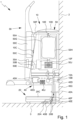
- Fig. 1 shows schematically a proposed cleaning system 1 with a proposed base station 10.
- FIG. 1 shows the cleaning system 1 or the base station 10 in the installed/mounted state or in the usual position of use, in which the base station 10 (rear) rests or is attached to a wall 2 and preferably (floor side) rests on a floor 3 or ends or is arranged close to the floor.
- the cleaning system 1 is preferably equipped with several components.
- the cleaning system 1 - in addition to the base station 10 - has at least one (mobile) cleaning device 20, 30, wherein the cleaning device 20, 30 can be coupled fluidically and/or electrically to the base station 10, in particular in order to empty/vacuum out and/or electrically charge the cleaning device 20, 30, as will be explained in more detail below.
- the cleaning device 20, 30 can be coupled fluidically and/or electrically to the base station 10, in particular in order to empty/vacuum out and/or electrically charge the cleaning device 20, 30, as will be explained in more detail below.
- the cleaning system 1 has several, here two different, cleaning devices 20, 30, with a first cleaning device 20 being designed as a vacuum robot and a second cleaning device 30 as a handheld vacuum cleaner.
- a first cleaning device 20 being designed as a vacuum robot
- a second cleaning device 30 as a handheld vacuum cleaner.
- other configurations are also conceivable here, for example in which the cleaning system 1 has several vacuum robots.
- the use of the base station 10 with two cleaning devices 20, 30 is described below. However, it is also possible for the cleaning system 1 to have only one cleaning device 20, 30 or for the base station 10 to be used with only one cleaning device 20, 30.
- the cleaning system 1 is used in particular in interior spaces or for cleaning interior spaces. However, it is also possible in principle to use the cleaning system 1 in outdoor spaces/areas or to use it for cleaning outdoor spaces/areas.
- the base station 10 is designed for (electrical) charging and/or (automated) maintenance, in particular for emptying or vacuuming and/or filling, of one or more cleaning devices 20, 30.
- the cleaning devices 20, 30 are coupled to the base station 10, whereby a fluidic and/or electrical connection is established between the base station 10 and the cleaning devices 20, 30.
- connection/coupling of the cleaning devices 20, 30 to the base station 10 can be done manually - for example in the case of a handheld vacuum cleaner - or automatically or autonomously - for example in the case of a vacuum robot.
- the first cleaning device 20 connects automatically or autonomously to the base station 10 after a cleaning process and the second cleaning device 30 manually or by a User is hung in the base station 10 in order to electrically charge and/or vacuum or fill the cleaning devices 20, 30 by means of the base station 10.
- the base station 10 is preferably elongated and/or box-shaped or cabinet-like.
- the base station 10 is fixedly or immovably connected to the wall 2.
- the base station 10 can also be designed as a free-standing and/or mobile or movable device.
- the base station 10 is mounted on the wall 2 in such a way that the base station 10 rests on the floor 3 when installed and lies flat against the wall 2.
- the base station 10 is arranged at a distance from the floor 3 when installed or is suspended from the wall 2, as in Fig. 2 shown.
- the base station 10 is preferably constructed in several parts or in a modular manner.
- the base station 10 particularly preferably has several modules or can be expanded by one or more modules.
- the base station 10 has a base module 40 and/or a head module 50, in particular wherein the head module 50 is arranged (immediately) above the base module 40 in the position of use or in the installed state.
- the base module 40 is designed for electrical and/or fluidic connection of the first cleaning device 20 and/or the head module 50 is designed for electrical and/or fluidic connection of the second cleaning device 30. It is therefore provided to (electrically) charge, fill and/or empty the first cleaning device 20 by means of the base module 40 and/or the second cleaning device 30 by means of the head module 50, in particular from the side, from below and/or from above.
- the floor module 40 is preferably designed to supply the first cleaning device 20 with electrical energy or to Fig. 1 only schematically to charge the indicated accumulator 20A of the first cleaning device 20 if and/or as soon as the cleaning device 20 is connected to the base station 10.
- Fig. 1 shows the cleaning system 1 or the first cleaning device 20 in the coupling or connection position in which the cleaning device 20 is electrically connected to the base station 10 or the floor module 40.
- the floor module 40 forms a receptacle 40A for the first cleaning device 20 in order to at least partially accommodate the first cleaning device 20.
- the first cleaning device 20 can therefore at least partially move into the floor module 40 in order to establish a fluidic and/or electrical connection with the base station 10 or the floor module 40.
- the floor module 40 preferably has a particularly flat or ramp-shaped base part 40B, a rear wall 40C and/or a particularly box-like upper part 40D, preferably wherein the receptacle 40A is limited downwards by the base part 40B, on the rear wall side by the rear wall 40C and upwards by the upper part 40D.
- the base part 40B rests on the floor 3 and the rear wall 40C preferably rests on the wall 2.
- the base station 10 or the floor module 40 In order to electrically connect the base station 10 or the floor module 40 to the first cleaning device 20, the base station 10 or the floor module 40 has a (first) electrical connection 40E.
- the electrical connection 40E is preferably formed by one or more electrical contacts or - in particular for wireless energy transmission - by one or more coils, wherein the electrical contacts or coils are arranged on or in the base part 40B, the rear wall 40C and/or the upper part 40D, in particular on a side of the base part 40B, the rear wall 40C and/or the upper part 40D facing the receptacle 40A.
- the first cleaning device 20 has an electrical connection 20B corresponding to the electrical connection 40E of the floor module 40, which is preferably formed by one or more electrical contacts or - in particular for a wireless energy transmission - is formed by one or more coils on an outer side and/or a bottom side of the cleaning device 20.
- the base station 10, in particular the base module 40, is equipped with an optional power supply unit 10A - preferably with corresponding charging electronics - and/or a power connection 10B for connection to a power network indicated only schematically in order to enable a power supply to the first cleaning device 20, the second cleaning device 30, the base module 40 and/or the head module 50.
- an optional power supply unit 10A - preferably with corresponding charging electronics - and/or a power connection 10B for connection to a power network indicated only schematically in order to enable a power supply to the first cleaning device 20, the second cleaning device 30, the base module 40 and/or the head module 50.
- the base station 10, in particular the head module 50, is preferably designed to hold or partially accommodate the second cleaning device 30.
- the second cleaning device 30 can be fastened to the head module 50 or hung in the head module 50.
- the base station 10 in particular the head module 50, has a holder 10C to hold the second cleaning device 30, in particular in a form-fitting and/or force-fitting manner and/or above or at a distance from the floor 3.
- the holder 10C is formed by a hook, wherein the second cleaning device 30 has a bracket corresponding to the hook in order to hang the cleaning device 30.
- the second cleaning device 30 has a bracket corresponding to the hook in order to hang the cleaning device 30.
- other solutions are also possible here.
- the head module 50 has a particularly box-shaped housing 50A, preferably wherein the housing 50A has or forms the holder 10C.
- the second cleaning device 30 can preferably be attached to a front side 50C of the head module 50.
- the front side 50C has the holder 10C.
- solutions are also possible in which the second cleaning device 30 is connected or hung laterally on the base station 10 or the head module 50.
- the electrical connection between the base station 10 or the head module 50 and the second cleaning device 30 is made by or simultaneously with Attaching or mechanically coupling the cleaning device 30 to the base station 10 or the head module 50.
- the base station 10 or the head module 50 has a (second) electrical connection 50E.
- the electrical connection 50E is preferably formed by one or more electrical contacts or - in particular for wireless energy transmission - by one or more coils.
- the electrical contacts or coils are preferably arranged on or in the front side 50C of the head module 50.
- the electrical connector 50E is integrated into the holder 10C (as in Fig. 2 shown).
- the second cleaning device 30 preferably has a battery 30A and an electrical connection 30B corresponding to the electrical connection 50E of the head module 50, preferably wherein the electrical connection 30B is connected to the battery 30A of the second cleaning device 30 via one or more electrical lines.
- the electrical connection 30B of the second cleaning device 30 is preferably formed by one or more electrical contacts or - in particular for wireless energy transmission - by one or more coils on an outer side of the second cleaning device 30.
- the electrical connection between the base station 10 or the head module 50 and the second cleaning device 30 or its battery 30A is established by - wirelessly or wired - coupling the electrical connection 30B of the second cleaning device 30 to the electrical connection 50E of the head module 50.
- the electrical connection is established automatically when the second cleaning device 30 is hung or mechanically coupled to the base station 10 or the head module 50.
- the second cleaning device 30 is electrically connected to the base station 10 or the head module 50, in particular the electrical Connection 50E, so that the second cleaning device 30 or the battery 30A of the second cleaning device 30 is electrically connected to the base station 10 or the head module 50 and the battery 30A can be charged by means of the base station 10.
- the electrical connection 50E is supplied with power from the first power supply 10A.
- the head module 50 is (also) equipped with a second or separate power supply and/or second or separate power connection.
- the cleaning system 1 or the base station 10 is designed as a self-sufficient or mains-independent cleaning system.
- the cleaning system 1 or the base station 10 can have one or more solar modules and/or accumulators or be designed as a photovoltaic island system.
- the base module 40 and the head module 50 are preferably electrically connected to one another, in particular such that the electrical connection 40E of the base module 40 and the electrical connection 50E of the head module 50 are electrically connected to the (common) power supply 10A.
- the base station 10 is preferably designed - in addition to or as an alternative to the electrical connection - for the fluidic, in particular pneumatic, connection of at least one, preferably several, cleaning devices 20, 30.
- the base station 10 or the floor module 40 is preferably equipped with a (first) fluidic, in particular pneumatic, connection 40F.
- the fluidic connection 40F of the base station 10 or the floor module 40 is preferably arranged in the base part 40B, in the rear wall 40C or in the upper part 40D and/or formed by a nozzle, an opening or the like in the base part 40B, in the rear wall 40C or in the upper part 40D.
- the fluidic connection 40F is preferably arranged directly next to the electrical connection 40E.
- the rear wall 40C has the fluidic connection 40F.
- the first cleaning device 20 can thus connect fluidically to the base station 10 or the floor module 40 from the side.
- the fluidic connection 40F is integrated into the foot part 40B or the upper part 40D.
- the first cleaning device 20 can connect fluidically to the base station 10 or the floor module 40 from the bottom or top when it moves onto the foot part 40B or is located below the floor module 40.
- the first cleaning device 20 connects both fluidically and electrically to the base station 10 or the floor module 40 (automatically) when it moves onto the foot part 40B and/or against the rear wall 40C or is in the connection position.
- the base station 10 or the floor module 40 preferably has a (first) container 40G, a (first) filter 40H and/or a (first) working machine 40J, such as a blower or a pump, preferably wherein the fluidic connection 40F is fluidically connected to the container 40G, the filter 40H and/or the working machine 40J.
- the container 40G, the filter 40H and/or the working machine 40J are/is preferably arranged in the upper part 40D of the base module 40.
- the filter 40H is designed as a filter bag which is arranged in the container 40G and attached to an inlet of the container 40G.
- a fluidic connection is preferably established between a collecting container 20C of the first cleaning device 20, which is only indicated schematically, and the base station 10 or the floor module 40, in particular the container 40G or the working machine 40J.
- the working machine 40J is designed as a blower or is designed to convey suction material from the collection container 20C of the first cleaning device 20 into the container 40G of the base station 10 or to suck out the collection container 20C.
- the cleaning device 20 is thus fluidically connected, particularly preferably both fluidically and electrically, to the base station 10, in particular the base module 40, in particular in such a way that the collection container 20C of the first cleaning device 20 can be emptied or filled and/or the accumulator 20A can be charged.
- the container 40G preferably has a volume that is larger than the volume of the collection container 20C of the first cleaning device 20, preferably twice or three times, so that the entire contents of the collection container 20C can be accommodated by the container 40G.
- the head module 50 is designed for the fluidic connection of a cleaning device 20 or 30, here the second cleaning device 30.
- the base station 10 or the head module 50 has a (second) fluidic, in particular pneumatic, connection 50F, preferably wherein the fluidic connection 50F is formed by an opening, a nozzle or the like on the front side 50C of the head module 50.
- the fluidic connection 50F is preferably arranged directly next to the electrical connection 50E of the head module 50.
- the fluidic connection 50F of the head module 50 is integrated into the holder 10C for the second cleaning device 30 (as in Fig. 2 shown).
- the base station 10 or the head module 50 preferably has a (second) container 50G, a (second) filter 50H and/or a (second) working machine 50J, such as a blower or a pump, preferably wherein the fluidic connection 50F is fluidically connected to the container 50G, the filter 50H and/or the working machine 50J.
- a (second) container 50G preferably has a (second) container 50G, a (second) filter 50H and/or a (second) working machine 50J, such as a blower or a pump, preferably wherein the fluidic connection 50F is fluidically connected to the container 50G, the filter 50H and/or the working machine 50J.
- the cleaning device 30 is fluidically, particularly preferably both fluidically and electrically, connected to the base station 10, in particular the head module 50, in particular such that a collecting container 30C of the second cleaning device 30 can be emptied or filled and/or the accumulator 30A can be charged.
- the optional fluidic connection between the base station 10 or the head module 50 and the second cleaning device 30 or its collection container 30C is preferably also established automatically when the second cleaning device 30 is hung in the base station 10 or the head module 50.
- the filter 50H is preferably designed as a filter bag and/or arranged in the container 50G.
- the filter 50H is preferably connected to or attached to an inlet of the container 50G.
- the working machine 50J is designed as a blower and/or is designed to reduce the pressure in the container 50G and thus to convey suction material from the collecting container 30C of the second cleaning device 30 into the container 50G or to suck out the collecting container 30C.
- the base station 10 or the head module 50 is equipped with a flap 10D in order to open the base station 10, in particular the head module 50 or the Container 50G and/or the base module 40 or the container 40G, to open, to empty and/or to change the filter 50H or 40H.
- the flap 10D is designed as a removable or pivotable cover. However, it is also possible, for example, to provide the front side 50C with the flap 10D, as in Fig. 2 shown.
- suction material can be sucked out of the collection container 20C of the first cleaning device 20 via the fluidic connection 40F of the base module 40 and/or suction material can be sucked out of the collection container 30C of the second cleaning device 30 via the fluidic connection 50F of the head module 50 and transferred into the container 40G of the base module 40 or into the container 50G of the head module 50.
- suction material can be sucked out of the collection container 20C of the first cleaning device 20 via the fluidic connection 40F of the base module 40 and/or suction material can be sucked out of the collection container 30C of the second cleaning device 30 via the fluidic connection 50F of the head module 50 and transferred into the container 40G of the base module 40 or into the container 50G of the head module 50.
- a liquid such as a cleaning agent
- a liquid such as a cleaning agent
- the working machine(s) 40J or 50J is/are preferably designed (each) as a pump(s).
- the base module 40 and the head module 50 are preferably fluidically connected to one another or can be connected, in particular in order to fluidically connect the first cleaning device 20 to the head module 50 or the second cleaning device 30 to the base module 40 or to empty or fill (also) the second cleaning device 30 by means of the base module 40 or (also) the first cleaning device 20 by means of the head module 50.
- the fluidic connection 40F of the base module 40 and the fluidic connection 50F of the head module 50 are fluidically connected to a common container or a common working machine, in particular the container 40G or the working machine 40J of the base module 40 or the container 50G or the working machine 50J of the head module 50, in order to empty or fill the cleaning devices 20, 30 by means of the common container and/or the common working machine.
- both cleaning devices 20, 30 are fluidically connected to the head module 50 or its container 50G and/or its working machine 50J, so that the contents of the collection container 20C of the first cleaning device 20 and the contents of the collection container 30C of the second cleaning device 30 can be conveyed into the container 50G by means of the (common) working machine 50J.
- both cleaning devices 20, 30 could be fluidically connected to the base module 40 or its container 40G and/or its working machine 40J.
- the container 50G or the filter 50H has an inlet, wherein in the embodiment shown both cleaning devices 20, 30 or both fluidic connections 40F, 50F are fluidically connected or connected via corresponding lines to the inlet.
- the base station 10 preferably has an optional (controlled) shut-off device 10E, such as a shut-off flap or a valve, in order to control the air flow and/or the air flow.
- the shut-off device 10E can be used to optionally connect the first cleaning device 20 or the fluidic connection 40F or the second cleaning device 30 or the fluidic connection 50F to the container 50G or the filter 50H.
- the base station 10 preferably has a control device 10F which controls the (electrical) charging, emptying and/or filling of the cleaning devices 20, 30.
- the control device 10F is preferably electrically connected to the (first) electrical connection 40E, the (second) electrical connection 50E, the power supply unit 10A, the (first) working machine 40J, the (second) working machine 50J and/or the shut-off device 10E.
- the cleaning system 1 or the base station 10 is preferably modular and can be expanded by one or more modules.
- an existing module for example the base module 40
- another module for example the head module 50
- another cleaning device 20 can be connected to another module, for example the head module 50, in order to be able to connect another cleaning device 20, 30 to the base station 10 and/or to add additional functions to the base station 10, such as vacuuming.
- one or more functions can be taken over by the added module.
- both modules 40, 50 can be used to vacuum and charge the cleaning devices 20, 30, it is preferred that one or more functions are performed by the base module 40 or the head module 50.
- the second embodiment corresponds at least substantially to the first embodiment, so that - even if not explicitly stated - the explanations made in connection with the first embodiment apply accordingly to the second embodiment and vice versa.
- the embodiment described below has one or more features that are exclusively related to Fig. 1 described.
- one or more features of the second embodiment can also be provided in the first embodiment.
- the proposed method can be carried out both with the base station 10 according to the first embodiment and with the base station 10 according to the second embodiment.
- the base station 10 is designed to maintain the cleaning devices 20, 30 simultaneously and/or according to a prioritization - in particular predefined and/or electronically stored - in particular to empty or vacuum them and/or to fill them with a cleaning agent and/or to charge them (electrically), particularly preferably automatically or independently.
- the base station 10 has a blower as a working machine 40J or 50J in order to suck suction material out of the cleaning devices 20, 30.
- the cleaning devices 20, 30 can also be electrically charged and/or filled with a cleaning agent, for example, simultaneously or in a prioritized manner.
- the base station 10 can have one or more containers 40G or 50G, one or more filters 40H or 50H and/or one or more work machines 40J or 50J.
- the base station 10 has a container 50G, a filter 50H arranged in the container 50G, hereinafter referred to as filter device 70, and a working machine 50J.
- the container 50G is preferably elongated and/or at least substantially cylindrical.
- the container 50G is preferably arranged coaxially in the housing 50A.
- the main axis A of the preferably elongated base station 10 (also) forms a longitudinal axis of the container 50G.
- the container 50G or its longitudinal axis is aligned at least substantially vertically in the installed state of the base station 10.
- the container 50G is larger than the collection container 20C of the first cleaning device 20 and/or the collection container 30C of the second cleaning device 30, in particular by at least twice or three times, so that the entire contents of the collection container 20C of the first cleaning device 20 and/or the collection container 30C of the second cleaning device 30 can be accommodated by the container 50G.
- the volume of the container 50G is larger than the combined volume of the collection container 20C of the first cleaning device 20 and the collection container 30C of the second cleaning device 30, in particular by at least double or triple. In this way, it is possible to accommodate the entire contents of both collection containers 20C, 30C of the cleaning devices 20, 30 in the container 50G.
- the container 50G preferably has a volume of more than 1 l or 1.5 l, particularly preferably more than 2 l or 3 l.
- the container 50G is fluidically connected via a first or lower supply line 10J to the first fluidic connection 40F, via a second or upper supply line 10K to the second fluidic connection 50F and/or via a particularly lateral suction line 10L to the working machine 50J and/or an outlet in the housing 50A.
- the lines 10J, 10K and 10L are arranged such that air can flow axially or from above and below into the container 50G and can flow radially or laterally out of the container 50G.
- the first supply line 10J opens axially from below and the second supply line 10K opens axially from above into the container 50G.
- This enables a particularly simple air flow and a particularly compact design of the base station 10.
- the first supply line 10J is guided laterally past the container 50G in order to open into the second supply line 10K or together with the second supply line 10K into the container 50G, as in Fig. 1 shown.
- the container 50G is preferably designed to accommodate the filter device 70.
- the filter device 70 is preferably a (disposable) filter, in particular a (disposable) filter cartridge, which is preferably exchanged after use or when a certain filling quantity is reached or replaced by a new filter or a new filter cartridge.
- the container 50G is accessible or openable via the flap 10D, in particular in order to insert or remove the filter device 70.
- the flap 10D is preferably arranged on the front side 50C of the base station 10, in particular such that the container 50G can be opened from the front or on the front side 50C of the base station 10 and the filter device 70 can be replaced.
- Fig. 2 shows the filter device 70 in the inserted state, in which the filter device 70 is fluidically connected to the lines 10J, 10K and 10L.
- the filter device 70 has - at least in the inserted state - an elongated or cylindrical shape and/or a shape corresponding to the container 50G.
- the filter device 70 is arranged coaxially in the housing 50A.
- the main axis A of the base station 10 also forms a longitudinal axis of the filter device 70.
- the filter device 70 or its longitudinal axis is aligned at least substantially vertically when inserted. In this way, the installation space of the base station 10 is used optimally.
- the filter device 70 preferably has a first or lower connection part 70A, a second or upper connection part 70B, a filter element or medium 70C and/or a filter chamber 70D, preferably wherein the connection parts 70A, 70B axially delimit the filter chamber 70D and the filter element 70C radially delimits the filter chamber 70D.
- the connecting parts 70A, 70B preferably each form an end face and/or an axial end of the preferably elongated or cylindrical filter device 70.
- the filter element 70C is preferably arranged between the first connection part 70A and the second connection part 70B.
- the connecting parts 70A, 70B are preferably each rigid and/or formed by a rigid, preferably plate- or disk-like, element.
- the filter element 70C is preferably flexible and/or formed by a particularly flexible and/or multi-layered filter material or medium, such as a fabric, paper and/or a nonwoven fabric.
- the filter device 70 in particular the filter element 70C, is folded and/or designed as an extendable bellows. In this way, it is possible to reduce the transport size of the filter device 70.
- the filter device 70 preferably has a first or lower connection opening 70E and a second or upper connection opening 70F, preferably wherein the connection openings 70E, 70F are arranged on different end sides of the filter device 70.
- the first connection opening 70E is arranged in the first connection part 70A and the second connection opening 70F is arranged in the second connection part 70B.
- connection openings 70E, 70F makes it possible to fill the filter device 70 - in particular simultaneously - from different sides or from above and below. In this way, the air flow in the base station 10 is simplified. In particular, no separate line is required that runs alongside the container 50G and guides air from bottom to top or vice versa. This enables a particularly compact design of the base station 10.
- the filter device 70 has only one connection opening 70E or 70F, as already explained in connection with the first embodiment.
- the filter device 70 is preferably connected to the first fluidic connection 40F of the base station 10 via the first connection opening 70E or the first supply line 10J and to the second fluidic connection 50F of the base station 10 via the second connection opening 70F or the second supply line 10K.
- air can be sucked into the filter chamber 70D via the first connection opening 70E or the first supply line 10J or from below and via the second connection opening 70F or the second supply line 10K or from above.
- the filter device 70 has a first or lower closure or non-return flap 70G and a second or upper closure or non-return flap 70H for retaining suction material, wherein the first non-return cap 70G is assigned to the first connection opening 70E and the second non-return cap 70H is assigned to the second connection opening 70F.
- connection openings 70E, 70F can be closed or opened by the non-return valves 70G, 70H.
- the connection openings 70E, 70F are (exclusively) actuated mechanically or by the air flow, in particular closed or opened.
- the check valves 70G, 70H are each formed by at least one flexible/bendable element, such as a rubber flap, which bends in the direction of flow or only releases the respective connection opening 70E or 70F when air is sucked in via the corresponding connection opening 70E or 70F.
- a flexible/bendable element such as a rubber flap
- the filter chamber 70D is preferably divided into several, here two, filter chambers 70K, 70L.
- the filter device 70 has a partition wall 70J which is arranged in the filter space 70D and/or divides the filter space 70D into a first or lower filter chamber 70K and a second or upper filter chamber 70L.
- the first connection opening 70E is preferably assigned to the first filter chamber 70K and the second connection opening 70F to the second filter chamber 70L.
- the first connection opening 70E thus forms an inlet for the first filter chamber 70K and the second connection opening 70F forms an inlet for the second filter chamber 70L.
- the filter chambers 70K, 70L are preferably of the same size, but can also be of different sizes, preferably with the first filter chamber 70K being smaller than the second filter chamber 70L, as in Fig. 2 indicated.
- the partition wall 70J is airtight or impermeable.
- the partition wall 70J it is also possible for the partition wall 70J to be permeable or to be formed by a permeable material, in particular a filter material.
- the partition wall 70J is arranged at the level of the outlet of the container 50G in order to enable uniform suction of the filter chambers 70K, 70L.
- the filter device 70 in particular the first connection part 70A and/or the second connection part 70B, are or are preferably fastened/held in the container 50G in a form-fitting or force-fitting manner.
- the base station 10, in particular the container 50G, has a holder 50K to hold the filter device 70 - in particular at the top and bottom - in the container 50G.
- the base station 10, in particular the container 50G, preferably has a first or lower holding part 50L for the first connection part 70A and a second or upper holding part 50M for the second connection part 70B, preferably wherein the holding parts 50L, 50M form the holder 50K.
- the first holding part 50L is preferably designed to hold the first connection part 70A in a form-fitting and/or force-fitting manner or to fix it at the bottom.
- the first holding part 50L is formed by one or more snap hooks that engage around the first connection part 70A.
- the second holding part 50M is preferably designed to hold the second connection part 70B in a form-fitting and/or force-fitting manner or at the top.
- the second holding part 50M is formed by a groove or a slot into which the second connection part 70B is inserted/hung.
- the filter device 70 is replaceable or removable from the container 50G.
- the Fig. 3A to 3C the insertion of the filter device 70 into the base station 10 is explained in more detail.
- the filter device 70 in particular the filter space 70D or the filter chambers 70K, 70L, is or are reduced or compressed in the delivery state of the filter device 70 - preferably by folding the filter element 70C - preferably to less than 90% or 80%, particularly preferably to less than 60% or 40%, of the volume of the filter device 70, in particular the filter space 70D or the filter chambers 70K, 70L, in the inserted or (fully) expanded state of the filter device 70.
- Fig. 3A shows the base station 10 with the flap 10D swung open or the container 50G opened and the filter device 70 in the delivery state or in the compressed state.
- the filter device 70 is only expanded or pulled apart in the base station 10 or in the container 50G.
- the filter device 70 is preferably first attached at the top or to the second holding part 50M, in particular pushed into the second holding part 50M, and (subsequently) pulled apart or unfolded.
- first the second connection part 70B is inserted or pushed into the holder 50K or the second holding part 50M and then the first connection part 70A is pulled downwards or in the direction of the first holding part 50L.
- the filter device 70 in particular the first connection part 70A, at the bottom or on the first holding part 50L and then to pull the second connection part 70B upwards or in the direction of the second holding part 50M.
- Fig. 3B shows the filter device 70 in the inserted but not yet fully expanded state.
- Fig. 3C shows the filter device 70 in the fully expanded state, in which the first connection part 70A is attached to the first holding part 50L and the second connection part 70B is attached to the second holding part 50M.
- the flap 10D is closed, preferably airtight or in such a way that air flows into the container 50G exclusively via the supply lines 10J, 10K when the working machine 50J is in operation.
- the cleaning devices 20, 30 are (automatically) emptied/vacuum cleaned by the base station 10 simultaneously or according to a prioritization or one after the other, particularly preferably either simultaneously or according to a prioritization.
- the air flow in the base station 10 can be changed in the connection position of the cleaning devices 20, 30, in particular in order to be able to vacuum either exclusively one cleaning device 20 or 30 or both cleaning devices 20, 30 (simultaneously).
- the base station 10 has the shut-off device 10E, preferably wherein the shut-off device 10E is designed as a shut-off flap and is arranged in one of the supply lines 10J or 10K.
- the base station 10 has two shut-off devices 10E and 10M - in particular controlled or connected to the control device 10F - preferably wherein the first shut-off device 10E is assigned to the first supply line 10J and the second shut-off device 10M is assigned to the second supply line 10K.
- first shut-off device 10E it is possible to control the flow in the first supply line 10J or to selectively open or to close or to selectively establish or interrupt a fluidic connection between the filter space 70D, in particular the first filter chamber 70K, and the first cleaning device 20, in particular its collecting container 20C.
- the second shut-off device 10M it is possible to control the flow in the second supply line 10K or to selectively open or close the second supply line 10K or to selectively establish or interrupt a fluidic connection between the filter space 70D, in particular the second filter chamber 70L, and the second cleaning device 30, in particular its collecting container 30C.
- shut-off device 10E or 10M is used to empty or vacuum the cleaning devices 20 or 30 simultaneously and/or one after the other.
- the (first) shut-off device 10E can be designed as a 3/2- or 3/3-way valve that is connected to both supply lines 10J, 10K and the inlet to the container 50G.
- the control unit 10F is designed to control the shut-off devices 10E, 10M - in particular independently of one another - i.e. to selectively close or open them.
- the shut-off devices 10E, 10M preferably each have a corresponding actuator (not shown) which is controlled by the control unit 10F.
- shut-off devices 10E, 10M or the supply lines 10J, 10K are preferably normally closed and/or are preferably only (automatically) activated or opened when the associated cleaning device 20 or 30 is connected to the base station 10 or has assumed the connection position. In this way, suction material is prevented from escaping from the base station 10 or the container 50G.
- the shut-off devices 10E, 10M are controlled or operated independently of one another. In this way, it is possible to open or close only one or (simultaneously) both shut-off devices 10E, 10M. or to empty/vacuum only one or (simultaneously) both cleaning devices 20, 30.
- shut-off device 10E or 10M for example the first shut-off device 10E
- a shut-off device 10E or 10M for example the first shut-off device 10E
- another shut-off device 10E or 10M for example the second shut-off device 10M
- second shut-off device 10M for example the second cleaning device 30.
- the suction process i.e. the emptying/suctioning of the cleaning devices 20 or 30, is preferably started by opening the respective shut-off device 10E or 10M.
- the working machine 50J is preferably activated or switched on (immediately) before, together with or (immediately) after the opening of the respective shut-off device 10E or 10M, in particular by means of the control device 10F.
- the suction process of the cleaning devices 20 or 30 is preferably terminated by closing the respective shut-off device 10E or 10M.
- the working machine 50J is preferably deactivated or switched off (immediately) before, together with or (immediately) after the closing of the respective shut-off device 10E or 10M.
- the suction process in particular the opening of the respective shut-off device 10E or 10M and/or the activation of the working machine 50J, can be started immediately or with a time delay, for example 10 seconds, after connecting the cleaning devices 20, 30 (automatically).
- the suction process in particular the opening of the respective shut-off device 10E or 10M and/or activation of the working machine 50J, can also be carried out depending on the filling level of the respective collecting container 20C or 30C, in particular only when a predefined filling level of the respective collection container 20C or 30C, (automatically) carried out or started.
- the cleaning devices 20, 30 are equipped with appropriate sensors (not shown) to determine the fill level of the collection containers 20C and 30C, respectively.
- a cleaning device 20 or 30 is connected to the base station 10, for example in order to charge the cleaning device 20 or 30 (electrically), but is not vacuumed because the fill level of the respective collection container 20C or 30C has not yet reached or exceeded a predefined value and, for example, a (further) cleaning process with the cleaning device 20 or 30 is still possible.
- the suction process is carried out for a specific or predefined period of time, for example 10 or 20 seconds, or is terminated depending on the fill level of the respective collection container 20C or 30C, in particular after the fill level of the respective collection container 20C or 30C falls below a predefined fill level.
- the respective shut-off devices 10E or 10M and/or the working machine 50J are (automatically) closed or deactivated after a specific or predefined period of time, for example 10 or 20 seconds, or depending on the fill level of the respective collecting container 20C or 30C, in particular after the fill level of the respective collecting container 20C or 30C falls below a predefined fill level.
- the first supply line 10J or the first shut-off device 10E is opened or the suction process is started as soon as the first cleaning device 20 is connected to the base station 10 or is in the connection position.
- the first supply line 10J or the first shut-off device 10E is (automatically) closed.
- the second supply line 10K or the second shut-off device 10M is preferably additionally opened, in particular in order to vacuum both cleaning devices 20, 30 at the same time.
- the power, in particular the speed, of the working machine 50J is increased - at least temporarily - when both cleaning devices 20 and 30 are connected to the base station 10 or are being vacuumed at the same time and/or both shut-off devices 10E, 10M are open.
- the cleaning devices 20, 30 can (always) be vacuumed evenly or with the same power per cleaning device 20, 30, regardless of whether only one vacuuming process takes place or several vacuuming processes take place at the same time.
- the power, in particular the speed, of the working machine 50J is (again) reduced if a cleaning device 20 or 30 has been emptied before another cleaning device 20 or 30 and/or a shut-off device 10E or 10M is closed and another shut-off device 10E or 10M remains open.
- suction process of a cleaning device 20 or 30, for example the first cleaning device 20 is (temporarily) stopped or interrupted when another cleaning device 20 or 30, for example the second cleaning device 30, is connected to the base station 10.
- the first supply line 10J or the first shut-off device 10E is closed or the suction process of the first cleaning device 20 is interrupted and (instead) the second supply line 10K or the second shut-off device 10M is opened or the suction process of the second cleaning device 30 is started when the second cleaning device 30 is connected to the base station 20, in particular in order to exclusively or primarily vacuum the second cleaning device 30.
- the second cleaning device 30 has priority over the first cleaning device 20, i.e. is emptied and/or filled with priority/priority over the first cleaning device 20 by means of the base station 10.
- the cleaning devices 20, 30 are emptied/vacuumed by the base station 10 according to a prioritization.
- the emptying/vacuum extraction and/or filling of the first cleaning device 20 is only started or only started again when the second cleaning device 30 is removed from the base station 10 and/or is used by a user.
- the base station 10 has one or more sensors 10N, 10P to detect whether the first cleaning device 20 or the second cleaning device 30 is connected to the base station 10.
- the base station 10 has a first or lower sensor 10N and a second or upper sensor 10P, wherein the first sensor 10N is assigned to the base module 40 or the first cleaning device 20 and the second sensor 10P is assigned to the head module 50 or the second cleaning device 30.
- the first sensor 10N it is possible to detect whether the first cleaning device 20 is in the connection position, in particular below the base station 10, and/or can be fluidically coupled to the base station 10.
- the second sensor 10P it is possible to detect whether the second cleaning device 30 is in the connection position, in particular is hung in the base station 10, and/or can be fluidically coupled to the base station 10.
- the sensors 10N, 10P can, for example, be resistive, inductive, magnetic, capacitive, piezoelectric and/or optoelectronic sensors.
- the electrical connections 40E or 50E can be used for the detection of the cleaning devices 20, 30 or for the sensors 10N, 10P.
- the cleaning system 1 or the base station 10 can be coupled with other devices (in terms of data technology).
- the cleaning system 1 or the base station 10 is designed for data exchange or signal transmission with other devices.
- the cleaning system 1 is equipped with a mobile device 4, such as a tablet, smartphone or the like, and/or a central device 5 and/or can be connected (for data purposes).
- a mobile device 4 such as a tablet, smartphone or the like
- a central device 5 and/or can be connected (for data purposes).
- a central device in the sense of the present invention is preferably a computer, a server or a server network.
- a central device can also be a virtual unit of several computers and/or servers and/or be implemented through so-called cloud computing.
- the mobile device 4 and/or the central device 5 are spatially separated and/or spaced apart from the base station 10.
- a wired or wireless data connection can be established between the base station 10, the first cleaning device 20, the second cleaning device 30, the mobile device 4 and/or the central device 5, in particular in order to transmit a signal and/or information or to exchange it between the base station 10, the first cleaning device 20, the second cleaning device 30, the mobile device 4 and/or the central device 5.
- the data exchange or signal transmission between the cleaning devices 20, 30 and the base station 10 can take place directly or indirectly, in particular via the mobile device 4 or the central device 5.
- a signal in the sense of the present invention is preferably a means for transmitting information, a (modulated) wave, in particular in a conductor, a bit sequence, a packet in the information technology sense or the like.
- a signal in the sense of the present invention can be transmitted via a wireless or wired data connection.
- one or more pieces of information are assigned to a signal and/or contained in the signal, which can be transmitted by means of the signal.
- the base station 10 In order to enable data exchange or to transmit a signal between the base station 10, the first cleaning device 20, the second cleaning device 30, the mobile device 4 and/or the central device 5, the base station 10 preferably has a communication device 10Q, the first cleaning device 20 has a first communication device 20Q and/or the second cleaning device 30 has a second communication device 30Q.
- the communication device 10Q or the communication devices 20Q, 30Q preferably have (each) a receiver for receiving and/or a transmitter for sending a signal.
- the communication device 10Q or the communication devices 20Q, 30Q have a radio interface, in particular a WPAN interface, a near-field communication interface, in particular an NFC interface, a WLAN interface or another, particularly preferably wireless interface.
- the electrical connections 20B, 30B are used for the preferably wired data exchange between the base station 10, the first cleaning device 20 and/or the second cleaning device 30, in particular when the cleaning devices 20, 30 are in the connection position.
- the suction process or the emptying of the cleaning devices 20, 30 is preferably started/carried out automatically or independently, in particular as soon as the cleaning devices 20, 30 are in the connection position or are detected by the sensors 10N, 10P.
- the base station 10 in particular the suction process or the emptying of the cleaning devices 20, 30, to be controlled, in particular started and/or terminated, by means of the mobile device 4, the central device 5 and/or a cleaning device 20 or 30.
- an (existing) control element of a cleaning device 20 or 30, such as the on/off switch, can be used to start the suction process of the cleaning device 20 or 30.
- the on/off switch can be used to start the suction process of the cleaning device 20 or 30.
- the first cleaning device 20, in particular the communication device 20Q, and/or the second cleaning device 30, in particular the communication device 30Q transmits information or a status signal with information, in particular about the cleaning process carried out, the fill level of the respective collection container 20C or 30C and/or the charge state of the respective accumulator 20A or 30A to the base station 10, in particular the communication device 10Q, the mobile device 4 and/or the central device 5, in particular in order to control, start or end the suction process and/or charging process by means of the base station 10.
- the data transmission preferably takes place when the cleaning devices 20, 30 are connected to the base station 10 and/or are in use. However, it is also possible for data transmission to take place continuously or at intervals between the base station 10 and the cleaning devices 20, 30.
- the base station 10 preferably has a data processing device 10R, preferably wherein the data processing device 10R is formed by a computer and/or has at least one (central) processor and/or a working memory.
- the data processing device 10R is preferably electrically connected to the communication device 10Q and the control unit 10F and/or spatially spaced from the communication device 10Q and the control unit 10F.
- the data processing device 10R can, however, also be integrated into the communication device 10Q or the control unit 10F.
- the data processing device 10R is designed to evaluate the signals or information received by means of the communication device 10Q and/or to transmit them as input values to the control unit 10F.
- the status signal transmitted by the cleaning devices 20, 30 is evaluated in order to - for example depending on the fill level - vacuum the first cleaning device 20 and/or the second cleaning device 30, i.e. to open the first shut-off device 10E and/or the second shut-off device 10M and/or to activate the work machine 50J.
- the mobile device 4 and/or the central device 5 may control the base station 10, in particular the shut-off devices 10E, 10M and/or the work machine 50J, depending on the received status signal.
- the base station 10 in particular the data processing device 10R, has a memory, such as a hard disk, an EPROM or the like, in which one or more pieces of information, in particular relating to the prioritization of the cleaning devices 20, 30, are or can be stored.
- a memory such as a hard disk, an EPROM or the like, in which one or more pieces of information, in particular relating to the prioritization of the cleaning devices 20, 30, are or can be stored.
- the mobile device 4 and/or the central device 5 contains or stores one or more pieces of information on the prioritization of the cleaning devices 20 and 30, respectively.
- the data processing device 10R, the mobile device 4 and/or the central device 5 access the memory in order to control the suction process based on the information stored there.
- the data processing device 10R, the mobile device 4 and/or the central device 5 can modify the data stored in the memory, in particular change the prioritization.
- the base station 10 is operated and/or configured using the mobile device 4.
- the mobile device 4 it is possible to use the mobile device 4 to change the prioritization of the cleaning devices 20, 30 and/or to configure a vacuuming process, in particular to change the (automatic) start, the length and/or the (automatic) end of a vacuuming process, and/or to start or end a vacuuming process.
- the base station 10 may have an input device, such as a touch-sensitive screen (not shown), which enables a user to configure the base station 10, in particular to change the prioritization, the (automatic) start, the length and/or the (automatic) end of a suction process, and/or to start or end a suction process.
- an input device such as a touch-sensitive screen (not shown)
- a touch-sensitive screen not shown
- prioritization in the sense of the present invention is preferably to be understood as a fixed and/or (electronically) stored priority/ranking of the cleaning devices 20 or 30 when servicing by means of the base station 10.
- the prioritization is or contains information assigned to the cleaning devices 20 or 30, preferably stored (electronically) in the mobile device 4, the central device 5 and/or the base station 10, which determines the sequence/order of maintenance and/or by means of which it is determined which cleaning device 20 or 30 is emptied and/or filled with priority or with secondary priority.
- shut-off devices 10E, 10M are controlled in such a way that the prioritized or priority cleaning device 20 or 30 is fluidically connected to the base station 10, in particular the filter device 70, and/or is sucked out by the base station 10 before the subordinate cleaning device 20 or 30.
Landscapes
- Engineering & Computer Science (AREA)
- Mechanical Engineering (AREA)
- Robotics (AREA)
- Chemical & Material Sciences (AREA)
- Chemical Kinetics & Catalysis (AREA)
- Cleaning In General (AREA)
- Mobile Radio Communication Systems (AREA)
- Electric Suction Cleaners (AREA)
- Electric Vacuum Cleaner (AREA)
- Manufacturing Of Printed Wiring (AREA)
- Cleaning By Liquid Or Steam (AREA)
Claims (13)
- Procédé pour faire fonctionner un système de nettoyage (1) avec plusieurs appareils de nettoyage mobiles (20, 30) et une station de base (10) pour les appareils de nettoyage (20, 30),
caractérisé en ce
que les appareils de nettoyage (20, 30) sont vidés simultanément par la station de base (10). - Procédé selon la revendication 1, caractérisé en ce que les appareils de nettoyage (20, 30) sont remplis simultanément avec un produit de nettoyage par la station de base (10).
- Procédé selon l'une quelconque des revendications précédentes, caractérisé en ce que la station de base (10) présente deux dispositifs de fermeture (10E, 10M) pour modifier le guidage d'air dans la station de base (10), de préférence dans lequel les dispositifs d'arrêt (10E, 10M) sont commandés indépendamment l'un de l'autre pour ouvrir ou pour fermer seulement un ou simultanément les deux dispositifs d'arrêt (10E, 10M).
- Procédé selon la revendication 3, caractérisé en ce que les dispositifs d'arrêt (10E, 10M) sont automatiquement fermés en fonction du niveau de remplissage des contenants de collecte (20C, 30C) des appareils de nettoyage (20, 30).
- Procédé selon l'une quelconque des revendications 3 ou 4, caractérisé en ce que le premier dispositif d'arrêt (10E) est fermé automatiquement dès que le premier appareil de nettoyage (20) est totalement vidé.
- Procédé selon l'une quelconque des revendications précédentes, caractérisé en ce que la puissance d'un engin de travail (50J) de la station de base (10) est augmentée au moins temporairement lorsque les deux appareils de nettoyage (20, 30) sont raccordés à la station de base (10), et/ou que la puissance de l'engin de travail (50J) est réduite lorsqu'un appareil de nettoyage (20, 30) a été vidé avant un autre appareil de nettoyage (20, 30).
- Dispositif filtrant (70) pour une station de base (10), dans lequel le dispositif filtrant (70) présente plusieurs ouvertures de raccordement (70E, 70F) pour remplir le dispositif filtrant (70),
caractérisé en ceque le dispositif filtrant (70) présente plusieurs clapets antiretour (70G, 70H),dans lequel un clapet antiretour (70G, 70H) est associé à chaque ouverture de raccordement (70E, 70F). - Dispositif filtrant selon la revendication 7, caractérisé en ce que les ouvertures de raccordement (70E, 70F) sont disposées sur différents côtés du dispositif filtrant (70).
- Dispositif filtrant selon la revendication 7 ou 8, caractérisé en ce que le dispositif filtrant (70) présente une paroi de séparation (70J), qui divise le dispositif filtrant (70) en deux chambres (70K, 70L), dans lequel chaque chambre (70K, 70L) présente une des ouvertures de raccordement (70E, 70F).
- Station de base (10) destinée à raccorder fluidiquement plusieurs appareils de nettoyage (20, 30) mobiles,
caractérisée en ceque la station de base (10) est réalisée pour vider simultanément les appareils de nettoyage (20, 30), et/ouque la station de base (10) présente un dispositif filtrant (70) selon l'une quelconque des revendications 7 à 9. - Station de base selon la revendication 10, caractérisée en ce que la station de base (10) présente un module de fond (40) et un module de tête (50) relié fluidiquement au module de fond (40), dans laquelle le module de fond (40) présente un raccord (40F) fluidique, en particulier pneumatique, pour un premier appareil de nettoyage (20) et/ou le module de tête (50) présente un raccord (50F) fluidique, en particulier pneumatique, pour un deuxième appareil de nettoyage (30).
- Station de base selon la revendication 10 ou 11, caractérisée en ce que la station de base (10) présente un engin de travail (50J), en particulier une soufflante et/ou une pompe, pour l'échange de fluide avec les appareils de nettoyage (20, 30).
- Station de base selon l'une quelconque des revendications 10 à 12, caractérisée en ce que la station de base (10) présente deux dispositifs d'arrêt (10E, 10M) pouvant être commandés indépendamment l'un de l'autre pour vider seulement un ou simultanément les deux appareils de nettoyage (20, 30).
Priority Applications (2)
| Application Number | Priority Date | Filing Date | Title |
|---|---|---|---|
| EP24207160.3A EP4470438B1 (fr) | 2019-04-18 | 2019-04-18 | Station de base et procédé de fonctionnement d'un système de nettoyage |
| EP23175213.0A EP4233666B1 (fr) | 2019-04-18 | 2019-04-18 | Procédé de fonctionnement d'un système de nettoyage, station de base et dispositif filtrant |
Applications Claiming Priority (2)
| Application Number | Priority Date | Filing Date | Title |
|---|---|---|---|
| EP19170267.9A EP3725206B1 (fr) | 2019-04-18 | 2019-04-18 | Procédé de fonctionnement d'un système de nettoyage, station de base et dispositif filtrant |
| EP23175213.0A EP4233666B1 (fr) | 2019-04-18 | 2019-04-18 | Procédé de fonctionnement d'un système de nettoyage, station de base et dispositif filtrant |
Related Parent Applications (1)
| Application Number | Title | Priority Date | Filing Date |
|---|---|---|---|
| EP19170267.9A Division EP3725206B1 (fr) | 2019-04-18 | 2019-04-18 | Procédé de fonctionnement d'un système de nettoyage, station de base et dispositif filtrant |
Related Child Applications (2)
| Application Number | Title | Priority Date | Filing Date |
|---|---|---|---|
| EP24207160.3A Division EP4470438B1 (fr) | 2019-04-18 | 2019-04-18 | Station de base et procédé de fonctionnement d'un système de nettoyage |
| EP24207160.3A Division-Into EP4470438B1 (fr) | 2019-04-18 | 2019-04-18 | Station de base et procédé de fonctionnement d'un système de nettoyage |
Publications (4)
| Publication Number | Publication Date |
|---|---|
| EP4233666A2 EP4233666A2 (fr) | 2023-08-30 |
| EP4233666A3 EP4233666A3 (fr) | 2023-09-20 |
| EP4233666C0 EP4233666C0 (fr) | 2024-11-27 |
| EP4233666B1 true EP4233666B1 (fr) | 2024-11-27 |
Family
ID=66239906
Family Applications (3)
| Application Number | Title | Priority Date | Filing Date |
|---|---|---|---|
| EP24207160.3A Active EP4470438B1 (fr) | 2019-04-18 | 2019-04-18 | Station de base et procédé de fonctionnement d'un système de nettoyage |
| EP23175213.0A Active EP4233666B1 (fr) | 2019-04-18 | 2019-04-18 | Procédé de fonctionnement d'un système de nettoyage, station de base et dispositif filtrant |
| EP19170267.9A Active EP3725206B1 (fr) | 2019-04-18 | 2019-04-18 | Procédé de fonctionnement d'un système de nettoyage, station de base et dispositif filtrant |
Family Applications Before (1)
| Application Number | Title | Priority Date | Filing Date |
|---|---|---|---|
| EP24207160.3A Active EP4470438B1 (fr) | 2019-04-18 | 2019-04-18 | Station de base et procédé de fonctionnement d'un système de nettoyage |
Family Applications After (1)
| Application Number | Title | Priority Date | Filing Date |
|---|---|---|---|
| EP19170267.9A Active EP3725206B1 (fr) | 2019-04-18 | 2019-04-18 | Procédé de fonctionnement d'un système de nettoyage, station de base et dispositif filtrant |
Country Status (6)
| Country | Link |
|---|---|
| US (1) | US11583152B2 (fr) |
| EP (3) | EP4470438B1 (fr) |
| JP (1) | JP2020185379A (fr) |
| CN (1) | CN111820809A (fr) |
| ES (2) | ES3054939T3 (fr) |
| TW (1) | TW202106216A (fr) |
Families Citing this family (32)
| Publication number | Priority date | Publication date | Assignee | Title |
|---|---|---|---|---|
| US12075957B2 (en) * | 2014-03-24 | 2024-09-03 | Intelligent Cleaning Equipment Holdings Co. Ltd. | Floor cleaning machines having intelligent systems, associated sub-assemblies incorporating intelligent systems, and associated methods of use |
| US11794141B2 (en) | 2021-01-25 | 2023-10-24 | Omachron Intellectual Property Inc. | Multiuse home station |
| WO2021177699A1 (fr) * | 2020-03-03 | 2021-09-10 | 엘지전자 주식회사 | Station d'aspirateur, système d'aspirateur et procédé de commande de station d'aspirateur |
| KR20210128786A (ko) * | 2020-04-17 | 2021-10-27 | 엘지전자 주식회사 | 스테이션 및 이를 포함하는 먼지 제거 시스템 |
| KR20210130655A (ko) * | 2020-04-22 | 2021-11-01 | 엘지전자 주식회사 | 청소기 스테이션 |
| KR20220046860A (ko) * | 2020-10-08 | 2022-04-15 | 엘지전자 주식회사 | 청소기 스테이션 및 이를 포함하는 청소기 시스템 |
| KR20220081703A (ko) * | 2020-12-09 | 2022-06-16 | 엘지전자 주식회사 | 청소기 스테이션 |
| KR20220081702A (ko) * | 2020-12-09 | 2022-06-16 | 엘지전자 주식회사 | 청소기 시스템 |
| CN116528739A (zh) * | 2020-12-16 | 2023-08-01 | Lg电子株式会社 | 吸尘器系统 |
| WO2022131710A1 (fr) * | 2020-12-16 | 2022-06-23 | 엘지전자 주식회사 | Système de nettoyage |
| CN113243850A (zh) * | 2021-02-10 | 2021-08-13 | 北京顺造科技有限公司 | 基站和表面清洁设备的通信方法及存储介质 |
| WO2022192742A1 (fr) * | 2021-03-11 | 2022-09-15 | Techtronic Cordless Gp | Station d'accueil d'aspirateur |
| CN113243859B (zh) * | 2021-04-26 | 2022-12-13 | 北京顺造科技有限公司 | 表面清洁设备和基站的流体交互方法及表面清洁系统 |
| CN113287980B (zh) * | 2021-04-27 | 2025-03-25 | 安克创新科技股份有限公司 | 基站和清洁系统 |
| BE1029361B1 (de) * | 2021-05-03 | 2022-12-05 | Miele & Cie | Wagen und Verfahren zum Ein- und Ausbringen von Reinigungsrobotern in und aus einem Wagen |
| JP7153867B1 (ja) * | 2021-05-31 | 2022-10-17 | パナソニックIpマネジメント株式会社 | 掃除機及び掃除機から塵埃を回収する回収装置 |
| EP4373377B1 (fr) * | 2021-07-23 | 2025-07-16 | Alfred Kärcher SE & Co. KG | Appareil de nettoyage de sol et système de nettoyage de sol autopropulséautoguidé |
| US12433461B2 (en) * | 2022-07-05 | 2025-10-07 | Sharkninja Operating Llc | Vacuum cleaner |
| CN115736703B (zh) * | 2021-09-03 | 2026-02-27 | 北京顺造科技有限公司 | 清洁液体供应装置、自动清洁设备及自动清洁系统 |
| EP4151135B1 (fr) * | 2021-09-15 | 2025-12-03 | Vorwerk & Co. Interholding GmbH | Appareil de nettoyage et système de nettoyage |
| CN113925407B (zh) * | 2021-11-18 | 2023-05-16 | 北京顺造科技有限公司 | 一种湿式表面清洁系统的集成站和表面清洁系统 |
| EP4458234A4 (fr) * | 2021-12-29 | 2026-03-04 | Lg Electronics Inc | Système de nettoyage et ensemble de raccordement pour système de nettoyage |
| CN114305232B (zh) * | 2022-01-18 | 2023-02-28 | 深圳银星智能集团股份有限公司 | 清洁设备 |
| CN116530890A (zh) * | 2022-01-25 | 2023-08-04 | 云鲸智能(深圳)有限公司 | 清洁设备的护理方法、基站、清洁系统及存储介质 |
| CN115277742A (zh) * | 2022-02-23 | 2022-11-01 | 智能清洁设备控股有限公司 | 用于管理机器人的系统和方法 |
| US20250194883A1 (en) * | 2022-03-11 | 2025-06-19 | Tineco Intelligent Technology Co., Ltd. | Charging and discharging method for cleaning device, and cleaning system |
| KR20230133655A (ko) * | 2022-03-11 | 2023-09-19 | 엘지전자 주식회사 | 청소기 스테이션 |
| JP7767997B2 (ja) * | 2022-03-16 | 2025-11-12 | 三菱電機株式会社 | 掃除機システム |
| CN114795029A (zh) * | 2022-04-28 | 2022-07-29 | 佛山市银星智能制造有限公司 | 清洁机器人基站、模组与控制清洁机器人模组工作的方法 |
| CN115005713A (zh) * | 2022-06-16 | 2022-09-06 | 广东栗子科技有限公司 | 一种清洁液投放水路系统及扫地机 |
| KR20240044962A (ko) * | 2022-09-29 | 2024-04-05 | 엘지전자 주식회사 | 청소기 스테이션 |
| KR20240082733A (ko) * | 2022-12-02 | 2024-06-11 | 엘지전자 주식회사 | 청소기 스테이션 |
Family Cites Families (21)
| Publication number | Priority date | Publication date | Assignee | Title |
|---|---|---|---|---|
| DE10357637A1 (de) | 2003-12-10 | 2005-07-07 | Vorwerk & Co. Interholding Gmbh | Selbstfahrendes oder zu verfahrendes Kehrgerät sowie Kombination eines Kehrgeräts mit einer Basisstation |
| EP2394553B1 (fr) * | 2006-05-19 | 2016-04-20 | iRobot Corporation | Élimination de débris de robots de nettoyage |
| KR101330734B1 (ko) | 2007-08-24 | 2013-11-20 | 삼성전자주식회사 | 로봇청소기와 도킹 스테이션을 구비하는 로봇청소기 시스템 |
| KR101483541B1 (ko) | 2010-07-15 | 2015-01-19 | 삼성전자주식회사 | 로봇청소기, 메인터넌스 스테이션 그리고 이들을 가지는 청소시스템 |
| WO2012094617A2 (fr) * | 2011-01-07 | 2012-07-12 | Irobot Corporation | Système de station d'évacuation |
| KR101467341B1 (ko) * | 2011-04-04 | 2014-12-03 | 연세대학교 산학협력단 | 보조 로봇을 갖는 로봇청소기 시스템 |
| DE102011054162A1 (de) | 2011-10-04 | 2013-04-04 | Vorwerk & Co. Interholding Gmbh | System aus einem selbsttätig verfahrbaren Reinigungsgerät und einer Basisstation sowie verfahrbares Reinigungsgerät und Verfahren zum Reinigen eines Schmutzbehälters |
| CA2833555C (fr) * | 2013-11-18 | 2020-03-10 | Canplas Industries Ltd. | Aspirateur a main et ensemble de fixation assurant la connexion a un systeme d'aspiration central |
| EP2894532B1 (fr) | 2014-01-10 | 2018-12-26 | Honda Research Institute Europe GmbH | Système de nettoyage de capteur pour un dispositif de robot autonome, station de base et procédé correspondant |
| JP5543042B1 (ja) | 2014-02-12 | 2014-07-09 | 株式会社コスモライフ | 台座 |
| DE102014119191A1 (de) | 2014-12-19 | 2016-06-23 | Vorwerk & Co. Interholding Gmbh | Basisstation für einen Staubsauger |
| DE102014119192A1 (de) * | 2014-12-19 | 2016-06-23 | Vorwerk & Co. Interholding Gmbh | Basisstation für einen Staubsauger |
| KR102626404B1 (ko) | 2016-05-09 | 2024-01-18 | 엘지전자 주식회사 | 청소기의 충전대 및 청소기의 거치대 |
| DE202016104069U1 (de) | 2016-07-26 | 2017-10-27 | Vorwerk & Co. Interholding Gmbh | Reinigungsgerät und Basisstation dafür |
| DE202016104066U1 (de) | 2016-07-26 | 2017-10-27 | Vorwerk & Co. Interholding Gmbh | Basisstation für ein Feuchtreinigungsgerät |
| US10829170B2 (en) * | 2017-04-19 | 2020-11-10 | Zhejiang University | Multifunctional robot system and method |
| DE102017113285A1 (de) | 2017-06-16 | 2018-12-20 | Vorwerk & Co. Interholding Gmbh | System mit mindestens zwei Reinigungsgeräten |
| AU2018204467A1 (en) | 2017-06-27 | 2019-01-17 | Bissell Inc. | Supply and/or disposal system for autonomous floor cleaner |
| AU2018336913B2 (en) * | 2017-09-22 | 2021-02-25 | Sharkninja Operating Llc | Hand-held surface cleaning device |
| CN108403017A (zh) | 2018-05-10 | 2018-08-17 | 深圳市宇辰智能科技有限公司 | 一种智能清洁机器人系统 |
| DE102019004417A1 (de) * | 2019-06-25 | 2020-12-31 | Vorwerk & Co. Interholding Gmbh | Verfahren, Basisstation und Reinigungssystem zum Aussaugen eines Reinigungsgeräts |
-
2019
- 2019-04-18 EP EP24207160.3A patent/EP4470438B1/fr active Active
- 2019-04-18 EP EP23175213.0A patent/EP4233666B1/fr active Active
- 2019-04-18 EP EP19170267.9A patent/EP3725206B1/fr active Active
- 2019-04-18 ES ES24207160T patent/ES3054939T3/es active Active
- 2019-04-18 ES ES19170267T patent/ES2956793T3/es active Active
-
2020
- 2020-04-13 US US16/846,560 patent/US11583152B2/en active Active
- 2020-04-16 CN CN202010299914.8A patent/CN111820809A/zh active Pending
- 2020-04-17 TW TW109112923A patent/TW202106216A/zh unknown
- 2020-04-17 JP JP2020074181A patent/JP2020185379A/ja active Pending
Also Published As
| Publication number | Publication date |
|---|---|
| EP4233666A2 (fr) | 2023-08-30 |
| EP4233666C0 (fr) | 2024-11-27 |
| ES2956793T3 (es) | 2023-12-28 |
| EP3725206A1 (fr) | 2020-10-21 |
| EP4470438A2 (fr) | 2024-12-04 |
| EP4233666A3 (fr) | 2023-09-20 |
| CN111820809A (zh) | 2020-10-27 |
| EP4470438C0 (fr) | 2025-10-15 |
| EP4470438A3 (fr) | 2025-03-05 |
| US11583152B2 (en) | 2023-02-21 |
| JP2020185379A (ja) | 2020-11-19 |
| TW202106216A (zh) | 2021-02-16 |
| EP3725206B1 (fr) | 2023-06-21 |
| EP4470438B1 (fr) | 2025-10-15 |
| US20200329933A1 (en) | 2020-10-22 |
| ES3054939T3 (en) | 2026-02-09 |
Similar Documents
| Publication | Publication Date | Title |
|---|---|---|
| EP4233666B1 (fr) | Procédé de fonctionnement d'un système de nettoyage, station de base et dispositif filtrant | |
| EP3033982B1 (fr) | Station de base pour un aspirateur | |
| EP3451889A1 (fr) | Système de nettoyage de sols | |
| DE102019004417A1 (de) | Verfahren, Basisstation und Reinigungssystem zum Aussaugen eines Reinigungsgeräts | |
| EP3514286B1 (fr) | Buse d'aspirateur pour un aspirateur et procédé de fonctionnement d'une buse d'aspirateur | |
| EP2946712B1 (fr) | Appareil de nettoyage de sol automobile équipé d'un véhicule suiveur suivant un véhicule meneur | |
| EP2598010B1 (fr) | Appareil de nettoyage de sol | |
| EP3581083B1 (fr) | Système de nettoyage comportant un robot d'alimentation et des satellites de nettoyage et procédé de nettoyage | |
| DE202016104066U1 (de) | Basisstation für ein Feuchtreinigungsgerät | |
| WO2018162091A1 (fr) | Appareil de nettoyage de sol automoteur et autoguidé | |
| WO2016184529A1 (fr) | Système de nettoyage à haute pression et unité d'éjection pour un tel système de nettoyage à haute pression | |
| DE102017112740A1 (de) | Haushaltsgerät zur automatischen Reinigung von Fußböden und Verfahren zur Steuerung eines Haushaltsgeräts | |
| EP3047781B1 (fr) | Aspirateur-traîneau à activation autonome, procédé d'aspiration de poussières et utilisation d'un aspirateur-traîneau utilisable à activation autonome | |
| DE102010038095A1 (de) | Entleerungsstation für einen akkumulatorbetriebenen Elektrostaubsauger | |
| EP3453301A1 (fr) | Réservoir pour un appareil de nettoyage du sol et appareil de nettoyage du sol | |
| DE102008011723B4 (de) | Staubsauger, insbesondere Haushalts-Staubsauger, sowie Verfahren zum Betreiben eines Staubsaugers | |
| DE102018116225A1 (de) | Reinigungsgerät | |
| DE102010016256A1 (de) | Verfahren zum Betreiben eines Staubsaugers, insbesondere eines selbsttätig verfahrbaren Saug- und/oder Kehrgeräts sowie ein derartiges Gerät und lagenförmiger Filtermaterialvorrat | |
| DE102017120759A1 (de) | Selbstfahrendes und selbstlenkendes Bodenreinigungsgerät, Bodenreinigungssystem und Verfahren zum Reinigen einer Bodenfläche | |
| DE102013108905A1 (de) | Zur Feuchtreinigung ausgebildetes Reinigungsgerät | |
| DE102014108217A1 (de) | Reinigungssystem | |
| DE10016552A1 (de) | Puderversorgungssystem | |
| EP3552714A1 (fr) | Transporteur de poudre destiné à transporter le poudre de revêtement, méthode de fabriquation de transportateur et centre d'alimentation en poudre pourvu de transporteur de poudre destiné à alimenter un centre d'alimentation en poudre | |
| EP4137025B1 (fr) | Procédé de fonctionnement d'une station de base pour un appareil de nettoyage | |
| EP3981312A1 (fr) | Dispositif de nettoyage |
Legal Events
| Date | Code | Title | Description |
|---|---|---|---|
| PUAI | Public reference made under article 153(3) epc to a published international application that has entered the european phase |
Free format text: ORIGINAL CODE: 0009012 |
|
| STAA | Information on the status of an ep patent application or granted ep patent |
Free format text: STATUS: THE APPLICATION HAS BEEN PUBLISHED |
|
| PUAL | Search report despatched |
Free format text: ORIGINAL CODE: 0009013 |
|
| AC | Divisional application: reference to earlier application |
Ref document number: 3725206 Country of ref document: EP Kind code of ref document: P |
|
| AK | Designated contracting states |
Kind code of ref document: A2 Designated state(s): AL AT BE BG CH CY CZ DE DK EE ES FI FR GB GR HR HU IE IS IT LI LT LU LV MC MK MT NL NO PL PT RO RS SE SI SK SM TR |
|
| AK | Designated contracting states |
Kind code of ref document: A3 Designated state(s): AL AT BE BG CH CY CZ DE DK EE ES FI FR GB GR HR HU IE IS IT LI LT LU LV MC MK MT NL NO PL PT RO RS SE SI SK SM TR |
|
| RIC1 | Information provided on ipc code assigned before grant |
Ipc: A47L 9/28 20060101AFI20230811BHEP |
|
| STAA | Information on the status of an ep patent application or granted ep patent |
Free format text: STATUS: REQUEST FOR EXAMINATION WAS MADE |
|
| 17P | Request for examination filed |
Effective date: 20240208 |
|
| RBV | Designated contracting states (corrected) |
Designated state(s): AL AT BE BG CH CY CZ DE DK EE ES FI FR GB GR HR HU IE IS IT LI LT LU LV MC MK MT NL NO PL PT RO RS SE SI SK SM TR |
|
| GRAP | Despatch of communication of intention to grant a patent |
Free format text: ORIGINAL CODE: EPIDOSNIGR1 |
|
| STAA | Information on the status of an ep patent application or granted ep patent |
Free format text: STATUS: GRANT OF PATENT IS INTENDED |
|
| INTG | Intention to grant announced |
Effective date: 20240320 |
|
| GRAJ | Information related to disapproval of communication of intention to grant by the applicant or resumption of examination proceedings by the epo deleted |
Free format text: ORIGINAL CODE: EPIDOSDIGR1 |
|
| STAA | Information on the status of an ep patent application or granted ep patent |
Free format text: STATUS: REQUEST FOR EXAMINATION WAS MADE |
|
| INTC | Intention to grant announced (deleted) | ||
| GRAP | Despatch of communication of intention to grant a patent |
Free format text: ORIGINAL CODE: EPIDOSNIGR1 |
|
| STAA | Information on the status of an ep patent application or granted ep patent |
Free format text: STATUS: GRANT OF PATENT IS INTENDED |
|
| INTG | Intention to grant announced |
Effective date: 20240712 |
|
| GRAS | Grant fee paid |
Free format text: ORIGINAL CODE: EPIDOSNIGR3 |
|
| GRAA | (expected) grant |
Free format text: ORIGINAL CODE: 0009210 |
|
| STAA | Information on the status of an ep patent application or granted ep patent |
Free format text: STATUS: THE PATENT HAS BEEN GRANTED |
|
| AC | Divisional application: reference to earlier application |
Ref document number: 3725206 Country of ref document: EP Kind code of ref document: P |
|
| AK | Designated contracting states |
Kind code of ref document: B1 Designated state(s): AL AT BE BG CH CY CZ DE DK EE ES FI FR GB GR HR HU IE IS IT LI LT LU LV MC MK MT NL NO PL PT RO RS SE SI SK SM TR |
|
| REG | Reference to a national code |
Ref country code: GB Ref legal event code: FG4D Free format text: NOT ENGLISH |
|
| REG | Reference to a national code |
Ref country code: CH Ref legal event code: EP |
|
| P01 | Opt-out of the competence of the unified patent court (upc) registered |
Free format text: CASE NUMBER: APP_60714/2024 Effective date: 20241112 |
|
| REG | Reference to a national code |
Ref country code: IE Ref legal event code: FG4D Free format text: LANGUAGE OF EP DOCUMENT: GERMAN |
|
| REG | Reference to a national code |
Ref country code: DE Ref legal event code: R096 Ref document number: 502019012573 Country of ref document: DE |
|
| U01 | Request for unitary effect filed |
Effective date: 20241224 |
|
| U07 | Unitary effect registered |
Designated state(s): AT BE BG DE DK EE FI FR IT LT LU LV MT NL PT RO SE SI Effective date: 20250114 |
|
| P04 | Withdrawal of opt-out of the competence of the unified patent court (upc) registered |
Free format text: CASE NUMBER: APP_1578/2025 Effective date: 20250110 |
|
| PG25 | Lapsed in a contracting state [announced via postgrant information from national office to epo] |
Ref country code: HR Free format text: LAPSE BECAUSE OF FAILURE TO SUBMIT A TRANSLATION OF THE DESCRIPTION OR TO PAY THE FEE WITHIN THE PRESCRIBED TIME-LIMIT Effective date: 20241127 Ref country code: IS Free format text: LAPSE BECAUSE OF FAILURE TO SUBMIT A TRANSLATION OF THE DESCRIPTION OR TO PAY THE FEE WITHIN THE PRESCRIBED TIME-LIMIT Effective date: 20250327 |
|
| PG25 | Lapsed in a contracting state [announced via postgrant information from national office to epo] |
Ref country code: ES Free format text: LAPSE BECAUSE OF FAILURE TO SUBMIT A TRANSLATION OF THE DESCRIPTION OR TO PAY THE FEE WITHIN THE PRESCRIBED TIME-LIMIT Effective date: 20241127 |
|
| PG25 | Lapsed in a contracting state [announced via postgrant information from national office to epo] |
Ref country code: NO Free format text: LAPSE BECAUSE OF FAILURE TO SUBMIT A TRANSLATION OF THE DESCRIPTION OR TO PAY THE FEE WITHIN THE PRESCRIBED TIME-LIMIT Effective date: 20250227 |
|
| PG25 | Lapsed in a contracting state [announced via postgrant information from national office to epo] |
Ref country code: GR Free format text: LAPSE BECAUSE OF FAILURE TO SUBMIT A TRANSLATION OF THE DESCRIPTION OR TO PAY THE FEE WITHIN THE PRESCRIBED TIME-LIMIT Effective date: 20250228 |
|
| PG25 | Lapsed in a contracting state [announced via postgrant information from national office to epo] |
Ref country code: PL Free format text: LAPSE BECAUSE OF FAILURE TO SUBMIT A TRANSLATION OF THE DESCRIPTION OR TO PAY THE FEE WITHIN THE PRESCRIBED TIME-LIMIT Effective date: 20241127 |
|
| PG25 | Lapsed in a contracting state [announced via postgrant information from national office to epo] |
Ref country code: RS Free format text: LAPSE BECAUSE OF FAILURE TO SUBMIT A TRANSLATION OF THE DESCRIPTION OR TO PAY THE FEE WITHIN THE PRESCRIBED TIME-LIMIT Effective date: 20250227 |
|
| U20 | Renewal fee for the european patent with unitary effect paid |
Year of fee payment: 7 Effective date: 20250424 |
|
| PG25 | Lapsed in a contracting state [announced via postgrant information from national office to epo] |
Ref country code: SM Free format text: LAPSE BECAUSE OF FAILURE TO SUBMIT A TRANSLATION OF THE DESCRIPTION OR TO PAY THE FEE WITHIN THE PRESCRIBED TIME-LIMIT Effective date: 20241127 |
|
| PG25 | Lapsed in a contracting state [announced via postgrant information from national office to epo] |
Ref country code: SK Free format text: LAPSE BECAUSE OF FAILURE TO SUBMIT A TRANSLATION OF THE DESCRIPTION OR TO PAY THE FEE WITHIN THE PRESCRIBED TIME-LIMIT Effective date: 20241127 |
|
| PG25 | Lapsed in a contracting state [announced via postgrant information from national office to epo] |
Ref country code: CZ Free format text: LAPSE BECAUSE OF FAILURE TO SUBMIT A TRANSLATION OF THE DESCRIPTION OR TO PAY THE FEE WITHIN THE PRESCRIBED TIME-LIMIT Effective date: 20241127 |
|
| PLBE | No opposition filed within time limit |
Free format text: ORIGINAL CODE: 0009261 |
|
| STAA | Information on the status of an ep patent application or granted ep patent |
Free format text: STATUS: NO OPPOSITION FILED WITHIN TIME LIMIT |
|
| REG | Reference to a national code |
Ref country code: CH Ref legal event code: L10 Free format text: ST27 STATUS EVENT CODE: U-0-0-L10-L00 (AS PROVIDED BY THE NATIONAL OFFICE) Effective date: 20251008 |
|
| 26N | No opposition filed |
Effective date: 20250828 |
|
| REG | Reference to a national code |
Ref country code: CH Ref legal event code: H13 Free format text: ST27 STATUS EVENT CODE: U-0-0-H10-H13 (AS PROVIDED BY THE NATIONAL OFFICE) Effective date: 20251125 |
|
| PG25 | Lapsed in a contracting state [announced via postgrant information from national office to epo] |
Ref country code: MC Free format text: LAPSE BECAUSE OF FAILURE TO SUBMIT A TRANSLATION OF THE DESCRIPTION OR TO PAY THE FEE WITHIN THE PRESCRIBED TIME-LIMIT Effective date: 20241127 |
|
| GBPC | Gb: european patent ceased through non-payment of renewal fee |
Effective date: 20250418 |
|
| PG25 | Lapsed in a contracting state [announced via postgrant information from national office to epo] |
Ref country code: GB Free format text: LAPSE BECAUSE OF NON-PAYMENT OF DUE FEES Effective date: 20250418 |
|
| PG25 | Lapsed in a contracting state [announced via postgrant information from national office to epo] |
Ref country code: CH Free format text: LAPSE BECAUSE OF NON-PAYMENT OF DUE FEES Effective date: 20250430 |
|
| PG25 | Lapsed in a contracting state [announced via postgrant information from national office to epo] |
Ref country code: IE Free format text: LAPSE BECAUSE OF NON-PAYMENT OF DUE FEES Effective date: 20250418 |