EP4233761B1 - Verfahren zur automatischen registrierung eines 3d-modells in einer anzeigevorrichtung eines medizinischen navigationssystems - Google Patents
Verfahren zur automatischen registrierung eines 3d-modells in einer anzeigevorrichtung eines medizinischen navigationssystems Download PDFInfo
- Publication number
- EP4233761B1 EP4233761B1 EP22158812.2A EP22158812A EP4233761B1 EP 4233761 B1 EP4233761 B1 EP 4233761B1 EP 22158812 A EP22158812 A EP 22158812A EP 4233761 B1 EP4233761 B1 EP 4233761B1
- Authority
- EP
- European Patent Office
- Prior art keywords
- model
- computed
- spatial transformation
- organ
- catheter
- Prior art date
- Legal status (The legal status is an assumption and is not a legal conclusion. Google has not performed a legal analysis and makes no representation as to the accuracy of the status listed.)
- Active
Links
Images


Classifications
-
- A—HUMAN NECESSITIES
- A61—MEDICAL OR VETERINARY SCIENCE; HYGIENE
- A61B—DIAGNOSIS; SURGERY; IDENTIFICATION
- A61B34/00—Computer-aided surgery; Manipulators or robots specially adapted for use in surgery
- A61B34/20—Surgical navigation systems; Devices for tracking or guiding surgical instruments, e.g. for frameless stereotaxis
-
- A—HUMAN NECESSITIES
- A61—MEDICAL OR VETERINARY SCIENCE; HYGIENE
- A61B—DIAGNOSIS; SURGERY; IDENTIFICATION
- A61B34/00—Computer-aided surgery; Manipulators or robots specially adapted for use in surgery
- A61B34/10—Computer-aided planning, simulation or modelling of surgical operations
-
- A—HUMAN NECESSITIES
- A61—MEDICAL OR VETERINARY SCIENCE; HYGIENE
- A61B—DIAGNOSIS; SURGERY; IDENTIFICATION
- A61B17/00—Surgical instruments, devices or methods
- A61B2017/00017—Electrical control of surgical instruments
- A61B2017/00022—Sensing or detecting at the treatment site
-
- A—HUMAN NECESSITIES
- A61—MEDICAL OR VETERINARY SCIENCE; HYGIENE
- A61B—DIAGNOSIS; SURGERY; IDENTIFICATION
- A61B17/00—Surgical instruments, devices or methods
- A61B2017/00017—Electrical control of surgical instruments
- A61B2017/00022—Sensing or detecting at the treatment site
- A61B2017/00039—Electric or electromagnetic phenomena other than conductivity, e.g. capacity, inductivity, Hall effect
- A61B2017/00044—Sensing electrocardiography, i.e. ECG
- A61B2017/00048—Spectral analysis
- A61B2017/00053—Mapping
-
- A—HUMAN NECESSITIES
- A61—MEDICAL OR VETERINARY SCIENCE; HYGIENE
- A61B—DIAGNOSIS; SURGERY; IDENTIFICATION
- A61B17/00—Surgical instruments, devices or methods
- A61B17/00234—Surgical instruments, devices or methods for minimally invasive surgery
- A61B2017/00238—Type of minimally invasive operation
- A61B2017/00243—Type of minimally invasive operation cardiac
-
- A—HUMAN NECESSITIES
- A61—MEDICAL OR VETERINARY SCIENCE; HYGIENE
- A61B—DIAGNOSIS; SURGERY; IDENTIFICATION
- A61B17/00—Surgical instruments, devices or methods
- A61B2017/00681—Aspects not otherwise provided for
- A61B2017/00694—Aspects not otherwise provided for with means correcting for movement of or for synchronisation with the body
- A61B2017/00699—Aspects not otherwise provided for with means correcting for movement of or for synchronisation with the body correcting for movement caused by respiration, e.g. by triggering
-
- A—HUMAN NECESSITIES
- A61—MEDICAL OR VETERINARY SCIENCE; HYGIENE
- A61B—DIAGNOSIS; SURGERY; IDENTIFICATION
- A61B17/00—Surgical instruments, devices or methods
- A61B2017/00681—Aspects not otherwise provided for
- A61B2017/00694—Aspects not otherwise provided for with means correcting for movement of or for synchronisation with the body
- A61B2017/00703—Aspects not otherwise provided for with means correcting for movement of or for synchronisation with the body correcting for movement of heart, e.g. ECG-triggered
-
- A—HUMAN NECESSITIES
- A61—MEDICAL OR VETERINARY SCIENCE; HYGIENE
- A61B—DIAGNOSIS; SURGERY; IDENTIFICATION
- A61B34/00—Computer-aided surgery; Manipulators or robots specially adapted for use in surgery
- A61B34/10—Computer-aided planning, simulation or modelling of surgical operations
- A61B2034/101—Computer-aided simulation of surgical operations
- A61B2034/105—Modelling of the patient, e.g. for ligaments or bones
-
- A—HUMAN NECESSITIES
- A61—MEDICAL OR VETERINARY SCIENCE; HYGIENE
- A61B—DIAGNOSIS; SURGERY; IDENTIFICATION
- A61B34/00—Computer-aided surgery; Manipulators or robots specially adapted for use in surgery
- A61B34/20—Surgical navigation systems; Devices for tracking or guiding surgical instruments, e.g. for frameless stereotaxis
- A61B2034/2046—Tracking techniques
- A61B2034/2051—Electromagnetic tracking systems
-
- G—PHYSICS
- G06—COMPUTING OR CALCULATING; COUNTING
- G06N—COMPUTING ARRANGEMENTS BASED ON SPECIFIC COMPUTATIONAL MODELS
- G06N20/00—Machine learning
Definitions
- the present invention relates to the field of medical image registration. More particularly, the invention relates to a method and a system for registration of a 3D model of an organ of a patient on a medical navigation system display device.
- Such virtual 3D model is generally built from a 3D image of the organ, obtained from a medical imaging method, such as computed tomography or CT-scan, fluoroscopy or MRI.
- the 3D image is processed to obtain a set of vertices which define a 3D model of the organ.
- the processing of the 3D image can also highlight features of the organ which can help the surgeon to detect medical intervention targets.
- the application EP3622478 from the applicant discloses a method for computing a 3D model of a patient's heart, and wherein the myocardial thickness is modelized to identify low thickness areas, or channels, in the myocardial wall.
- the surgeon then introduces a probe or a catheter into the patient's organ.
- This catheter allows a navigation system to generate an image of one or more areas of interest of the organ, which is displayed on a screen in order to help the surgeon to assess the position of the targets.
- the 3D model on which the medical intervention has been prepared has to be imported into this navigation system.
- the 3D model must be registered to the reference frame used by the navigation system.
- a navigation system operator manually moves and rotates the 3D model to match as best as possible the areas of interest generated by the navigation system.
- Such manual registration is therefore slow, complex and subject to inaccuracy.
- the tubular structure can be segmented from the 3D model.
- the invention thus proposes to compute a spatial transformation which, when applied to the 3D model, transforms the 3D model in order to match the 3D model vertices labelled as the tubular structure with the point cloud representing this tubular structure.
- the result of this spatial transformation on the 3D model is therefore a 3D model automatically registered in the same frame of reference than the spatial coordinates. Consequently, it can be displayed on the navigation system display with the current position of the catheter in a same patient's frame of reference.
- a same registration might be obtained with minimizing a predefined error metric between the result of the reversed spatial transformation one the reference point cloud and the 3D model segmentation.
- the landmark displayed on the navigation system might be an image, an icon or a logo displayed at the current sensor position, or a 3D model of the catheter with its tip displayed at the current sensor position.
- the reference point cloud might be displayed with being superimposed to the result of the computed spatial transformation on the 3D model.
- the method comprises a preliminary step of acquiring a 3D image and/or recording a 3D image of a patient's organ, particularly his heart or a region of his heart, the 3D model being computed from said 3D image.
- the 3D image may be acquired directly from an image acquisition device such as a scanner or MRI.
- the 3D image may be obtained from a recording medium on which it is stored, such as a local memory or a distant database, the 3D image having been acquired beforehand the method.
- the method according to the invention can include a step of segmenting one or more regions of interest in the 3D image or 3D model.
- the method according to the invention comprises a sub-step of segmenting a plurality of volumes in the 3D image or in the 3D model according to their thickness, in particular following a comparison of their thickness to a plurality of thickness levels, each voxel or each vertex being labelled according to the thickness of the volume to which it belongs.
- an image processing method is implemented to detect, segment or extract at least two volumes from the 3D image or from the 3D model by considering for each voxel of the 3D image or for each vertex of the 3D model the thickness of the latter and by comparing this thickness to a maximum threshold or to different thickness levels.
- the volumes can be segmented according to thickness levels of 1mm, 2mm, 3mm, 4mm and 5mm.
- the method according to the invention comprises a step of detecting at least one region of interest in the 3D image or in the 3D model, by identifying for example at least one region, for instance an isthmus in the case of a 3D image or model of a heart, such that it is comprised between two regions of lesser thickness.
- the method according to the invention comprises a step of classifying each region of interest by means of:
- regions of interest can be classified to assist the surgeon in quickly identifying intervention targets.
- several geometric criteria are taken together and combined in order to refine the classification of regions of interest.
- the step of detecting a region of interest and classifying this region of interest can be performed, at least partially, manually by a user.
- the method according to the invention comprises a step of detection and classification of at least one tubular structure in the 3D image or in the 3D model.
- the method might comprise a step of detection of a vessel, such as a coronary sinus, in the 3D image or in the 3D model.
- the step of detection and classification of a tubular structure might comprise a manual or an automatic detection of circles and/or of ellipses in at least a subset of 2D images composing the 3D image, each pixel of a 2D image belonging to a detected circle or a detected ellipse being classified as belonging to a detected tubular structure, and the pixels of two 2D images belonging to detected tubular structures with a generally identical shape and/or with generally identical dimensions and/or being generally positioned in the same area in the 2D images being classified as belonging to a same detected tubular structure.
- the step of detection and classification of a tubular structure might comprise an interpolation of the detected tubular structure to the rest of 2D images.
- the method comprises a step of identifying one or more areas in the 3D model segmentation and in the reference point cloud having at least one geometrical feature matching a predetermined criteria, and the computed spatial transformation is the spatial transformation which, when applied to the 3D model, minimizes the predefined error metric between the result of this spatial transformation on the 3D model segmentation and the reference point cloud in at least said one or more areas.
- the computed spatial transformation is the spatial transformation which, when applied to the 3D model, minimizes the predefined error metric between the result of this spatial transformation on the 3D model segmentation and the reference point cloud in at least said one or more areas.
- the computed spatial transformation is the spatial transformation which, when applied to the 3D model, minimizes the predefined error metric between the result of this spatial transformation on the 3D model segmentation and the reference point cloud only in said one or more identified areas.
- Said iterative estimation might be implemented as an Iterative Closest Point algorithm, or as a Robust Point Matching algorithm, or any suitable point-set registration algorithm in which the error metric might be weighted.
- the predefined error metric might be a Root Mean Square-based, or RMS-based, metric.
- said supplemental local data might be :
- At least one region of interest which corresponds to said supplemental local data, can be segmented in the 3D model and the computed spatial transformation is the spatial transformation which, when applied to the 3D model, minimizes the predefined error metric between the result of this spatial transformation on the 3D model segmented region of interest and a reference point cloud associated to said supplemental local data.
- electrical signals on the endocardium captured by a mapping catheter guided in a heart can be used to identify areas of low voltage, slow conduction, or abnormal activity. These areas are correlated with the presence of scars or channels on the heart, which can be segmented on the 3D model of the heart, due to their thickness, width, length and topology. It therefore possible to correct the initial registration achieved with the positioning sensors of the first catheter, with these supplemental information received from this other catheter.
- the method comprises a further step of periodically receiving spatial coordinates, computed from data received from the at least one sensor of the catheter inside a portion of said organ of the patient; a further step of modeling a periodic motion of said organ of the patient from said periodically received spatial coordinates and a further step of modifying the display positions of the landmark and the result of the computed spatial transformation on the 3D model on the navigation system display device based on said model of the periodic motion of said organ of the patient.
- a periodic motion of the patient such as its cardiac and/or respiratory motion, can therefore be compensated to avoid any perturbation in the display of the navigation system.
- the periodic motion of said organ might be modelized with computing an average set of spatial coordinates from received spatial coordinates over several periodic cycles.
- the modeling of the periodic motion of the organ might be implemented with a machine-learning algorithm, such as a support vector regressor or a relevance vector machine.
- said value relative to the error of registration might be the value of the predefined error metric between the result of the computed spatial transformation on the 3D model and the reference point cloud.
- the method comprises a further step of receiving a set of supplemental local data relative to said organ of the patient, computed from data received from at least one sensor of a catheter inside a portion of said organ of the patient, each supplemental local data being associated with spatial coordinates of said sensor, and a further step of displaying each supplemental local data on the result of the computed spatial transformation on the 3D model displayed on the navigation system display device, the displayed position of this supplemental local data being computed from its associated spatial coordinates. It therefore possible to project captured supplemental data on the 3D model displayed on the navigation system, to build a 3D augmented model of the organ.
- each supplemental local data might be displayed with an icon, a marking or a label being superimposed on a vertex of the 3D model, the position of which being determined from the supplemental local data associated spatial coordinates and said computed spatial transformation.
- each supplemental local data might be displayed with a vertex of the 3D model being modified, the position of which being determined from the supplemental local data associated spatial coordinates and said computed spatial transformation, and the color of which being modified depending on the value of the supplemental local data and according to a scalar or color map associating possible values of local data with colors.
- said supplemental local data might be supplemental electrical local data.
- Said supplemental electrical local data might be local electrical signals or local electrical information, such as local impedance, relative to said organ and received, directly or indirectly, from an electrode of the same catheter or from an other catheter.
- said supplemental local data might be supplemental mechanical local data.
- Said supplemental mechanical local data might be local mechanical property of the organ, such as the local elasticity of the tissue, received, directly or indirectly, from a pressure sensor of the same catheter or from an other catheter.
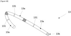
- the catheter is a flexible and/or steerable catheter.
- Each portion 13a may be flexible and/or steerable to facilitate the guiding of the distal portion 13b within the patient's tubular structure.
- each portion 13a may include one or more steering elements, operable from the catheter handle, to control the bending of this portion from a generally straight configuration to a curved configuration.
- the catheter 13 can be therefore bent to follow the general curvature of the patient's tubular structure.
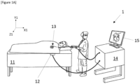
- each sensor 131 may be an at least three degree of freedom sensor, i.e., providing signals corresponding to a coordinate position of the sensor 131 in three-dimensional space within the reference frame X1, Y1, Z1.
- one or more sensors 131 may be six degree of freedom sensor which also provides signals relative a rotational position of the sensor relative to the external reference frame.
- any number of additional sensors capable of location within a predetermined number of degrees of freedom may be provided on each portion of the catheter.
- the tracking unit of the controller 14 receives signals provided by each sensor 131 and is configured to compute, from each received signal, spatial coordinates of a location of the corresponding sensor 131 within the reference frame X1, Y1, Z1.
- the system 1 also comprises a display device 15, which the controller 13 controls to present information to a surgeon to provide an assistance to the intervention.
- a 3D image 3D_CT of the patient's heart has been acquired from a CT-scan method, and a 3D model IH representing a thickness map of the patient's heart myocardium has been generated from the 3D image.
- an inner surface and an outer surface of the patient's myocardium have been modelized from the 3D image 3D_CT with defining a plurality of vertices to form a mesh.
- a plurality of volumes in the resulting model IH have been segmented according to their thickness with each vertex being labelled according to the thickness of the volume to which it belongs.
- the 3D model IH has its own frame of reference X2, Y2, Z2, which might be completely different from the frame of reference X1, Y1, Z1.
- At least one region R CH has been detected and segmented in the 3D model IH as being comprised between two regions of lesser thickness and has been classified as an ablation target, taking into account its thickness, its width, its length and its entrance and exit topologies.
- the resulting 3D model IH may therefore have helped the surgeon to prepare the catheter ablation intervention.
- a region R CS has been detected and segmented in the 3D model IH as being a tubular structure and has been classified as being all or part of the coronary sinus CS.
- step S02 to S04 might be executed by an other computing unit than the controller 14, and that steps S03 and/or S04 might be executed fully automatically by this computing or with a human assistance.
- the resulting 3D model IH might be stored on a recording medium, such as a memory of the controller 14 or an external memory support or a distant database through which it is accessible to the controller 14.
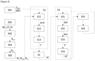
- a step 505 the 3D model IH in the frame of reference X2, Y2, Z2, with segmented regions R CH and R CS , is provided to the computing unit of the controller 14.
- a spatial transformation T allowing to register the 3D model IH in the frame of reference X1, Y1, Z1 of the reference point cloud RPC, is computed by the controller 14.
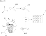
- step S1 has been shown on Figure 3 .
- the step S1 comprises a sub-step S11 consisting in the identification of one or more areas in the region R CS of the 3D model IH and in the reference point cloud RPC having at least one geometrical feature matching a predetermined criteria.
- the sub-step S11 consists in identifying areas AHC of the coronary sinus CS represented by the region R CS and by the reference point cloud RPC which have a curvature and/or a torsion exceeding a predetermined threshold.
- the curvature and the torsion of the reference point cloud RPC can be estimated by controller 14 with comparing the evolution of the vectors connecting the locations of each pair of sensors 131 during the catheter motion into the coronary sinus CS.
- Areas AHC corresponding to coronary sinus portions with a strong curvature and/or a strong torsion can be therefore segmented from both the region R CS of the 3D model IH and the reference point cloud RPC.
- other areas with specific geometrical features, such as a predefined shape, might also be segmented.
- weights are attributed to each vertex of the region R CS of the 3D model IH and to each point of the reference point cloud RPC, the weights attributed to vertices and points belonging to areas AHC being higher to the weights for other vertices and points.
- an Iterative Closest Point algorithm is executed by the controller 14 to iteratively estimate a spatial transformation T which, when applied to the 3D model IH, minimizes an error metric E between the result T(R CS ) of this spatial transformation T on the region R CS and the reference point cloud RPC, the predefined error metric taking into account the weights attributed to the vertices and points in the sub-step S12.
- E is a root mean square-based error metric
- N is the number of points of the reference point cloud RPC which match points of the region R CS
- RPC i and R CS,i are two matched points of the reference point cloud RPC and the region R CS
- ⁇ i is the weight attributed to these points
- T is the estimated spatial transformation to be applied to the 3D model IH
- ⁇ x,y ⁇ is the distance between two points x and y.
- the spatial transformation T which is estimated by the Iterative Closest Point (ICP) algorithm is constrained to a rigid transformation and is defined by a 4x4 matrix defining a rotation and a translation.
- ICP Iterative Closest Point
- sub-steps S11 and S12 might be skipped and the spatial transformation might be directly computed by the controller 14 at the step S13, from all the points of the reference point cloud RPC and the region R CS and with a non-weighted error metric.
- the sub-step S12 only might be skipped, and the spatial transformation might be computed by the controller 14 at the step S13, from the sole points of the reference point cloud RPC and the region R CS which belong to the areas AHC, and with a non-weighted error metric.
- the invention is not limited to the implementation of an Iterative Closest Point algorithm and that other suitable point-set registration algorithm, especially in which the error metric might be weighted, can be executed by the controller 14 for the implementation of the sub-step S13.
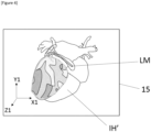
- a registered 3D model IH' is computed by the controller 14, with applying the estimated spatial transformation T to the whole 3D model IH.
- This registered 3D model IH' is then displayed on the display device 15, simultaneously to a landmark LM positioned, in the reference frame X1, Y1, Z1, at a current position of the catheter 13.
- the landmark LM is a 3D model of the catheter 13, represented in its current configuration and its current location in the reference frame X1, Y1, Z1.
- the value of the error metric E between the result of the computed spatial transformation T on the 3D model IH and the reference point cloud RPC might be displayed on the device 15, as a value relative to an error of registration.
- Steps S1 and S2 corresponds to an initial registration of the 3D model IH in the reference frame X1, Y1, Z1.
- this initial registration might be subject to slight errors, which can be corrected in a real-time correction step S3 described hereinafter.
- Figure 5 depicts the execution of this step.
- a second catheter (not represented) has been introduced into the patient's heart.
- This second catheter might be mapping catheter provided with one or more electrodes. These electrodes provide periodically to the controller 14 local electrical signals, captured on the endocardium and each associated with spatial coordinates, from which the controller 14 might generate an electrophysiological map EM of the heart, such as peak-to-peak voltage map.
- an electrophysiological map EM of the heart such as peak-to-peak voltage map.
- area ALV of low voltage, slow conduction, or abnormal activity can be segmented, by way of known methods executed by the controller 14, from the map EM.
Landscapes
- Health & Medical Sciences (AREA)
- Surgery (AREA)
- Engineering & Computer Science (AREA)
- Life Sciences & Earth Sciences (AREA)
- Biomedical Technology (AREA)
- Robotics (AREA)
- Nuclear Medicine, Radiotherapy & Molecular Imaging (AREA)
- Heart & Thoracic Surgery (AREA)
- Medical Informatics (AREA)
- Molecular Biology (AREA)
- Animal Behavior & Ethology (AREA)
- General Health & Medical Sciences (AREA)
- Public Health (AREA)
- Veterinary Medicine (AREA)
- Apparatus For Radiation Diagnosis (AREA)
Claims (9)
- Computerimplementiertes Verfahren zum Anzeigen eines 3D-Modells eines Organs eines Patienten auf einer Anzeigevorrichtung (15) eines Navigationssystems, das Verfahren umfassend:a. (S01) Empfangen einer Vielzahl von räumlichen Koordinaten (SXYZ), die aus Daten berechnet ist, die von mindestens einem Sensor (131) eines Katheters (13) im Inneren eines Abschnitts (CS) des Organs des Patienten empfangen werden; die Vielzahl der räumlichen Koordinaten eine Referenzpunktwolke (RPC) definiert, die den Abschnitt des Organs des Patienten darstellt;b. (S05) Empfangen einer Vielzahl von Punkten, wobei die Vielzahl von Punkten ein vordefiniertes 3D-Modell (IH) des Organs des Patienten definiert, wobei eine Untervielzahl von Punkten markiert ist, um eine 3D-Modellsegmentierung (Rcs) zu definieren,die dem Abschnitt des Organs des Patienten entspricht;c. (S1) Berechnen einer räumlichen Transformation (T), die, wenn sie auf das 3D-Modell angewendet wird, eine vordefinierte Fehlermetrik (E) zwischen dem Ergebnis (T(Rcs)) dieser räumlichen Transformation auf die 3D-Modellsegmentierung und die Referenzpunktwolke minimiert;d. (S2) Anzeigen eines Orientierungspunkts (LM) an einer aktuellen Position des Katheters, der aus der Vielzahl von räumlichen Koordinaten erhalten wird, und, gleichzeitig, des Ergebnisses (IH') der berechneten räumlichen Transformation auf dem 3D-Modell auf der Anzeigevorrichtung des Navigationssystems,wobei das Verfahren einen Schritt (S11) eines Identifizierens eines oder mehrerer Bereiche (AHC) in der 3D-Modellsegmentierung (Rcs) und in der Referenzpunktwolke (RPC) umfasst, die mindestens ein geometrisches Merkmal aufweisen, das mit einem zuvor bestimmten Kriterium übereinstimmt, und die berechnete räumliche Transformation (T) die räumliche Transformation ist, die, wenn sie auf das 3D-Modell (IH) angewendet wird, die vordefinierte Fehlermetrik (E) zwischen dem Ergebnis (T(Rcs)) dieser räumlichen Transformation auf die 3D-Modellsegmentierung und die Referenzpunktwolke in mindestens einem oder mehreren Bereichen minimiert;dadurch gekennzeichnet, dass der Schritt (S01) des Empfangens einer Vielzahl von räumlichen Koordinaten (SXYZ) den Empfang von mindestens einer ersten und einer zweiten Vielzahl von räumlichen Koordinaten umfasst, die aus Daten berechnet werden, die von mindestens einem ersten und einem zweiten Sensor (131) des Katheters (13) empfangen werden, und wobei der Schritt (S11) des Identifizierens eines oder mehrerer Bereiche (AHC) in der Referenzpunktwolke (RPC) eine Schätzung der Entwicklung der Krümmung und/oder der Torsion der Referenzpunktwolke aus der ersten und der zweiten Vielzahl von räumlichen Koordinaten umfasst.
- Verfahren nach Anspruch 1, wobei jeder Punkt der 3D-Modellsegmentierung (Rcs) und/oder die Referenzpunktwolke (RPC) mit einem Wert verknüpft ist, wobei der Wert von der Position des verknüpften Punkts in Bezug auf den einen oder die mehreren Bereiche (AHC) abhängt, wobei der Berechnungsschritt (S1) der räumlichen Transformation eine iterative Schätzung (S13) einer räumlichen Transformation (T) umfasst, die, für jede Iteration, umfasst:a. ein Unterschritt eines Übereinstimmens jedes Punkts von mindestens einem Teil des Ergebnisses (T(Rcs)) der aktuell geschätzten räumlichen Transformation auf der 3D-Modellsegmentierung mit einem Punkt der Referenzpunktwolke undb. einen Unterschritt eines Anpassens der aktuell geschätzten räumlichen Transformation gemäß der vordefinierten Fehlermetrik (E) zwischen dem Ergebnis der aktuell geschätzten räumlichen Transformation auf der 3D-Modellsegmentierung und der Referenzpunktwolke, wobei die vordefinierte Fehlermetrik auf einem mittleren Distanzwert zwischen den übereingestimmten Punkten basiert, gewichtet mit den verknüpften Werten.
- Verfahren nach einem der vorstehenden Ansprüche, wobei die berechnete räumliche Transformation (T) eine quadratische Matrix ist, die mindestens eine Rotation und/oder eine Translation definiert.
- Verfahren nach einem der vorstehenden Ansprüche, das Verfahren einen umfassend weiteren Schritt (S31) des Empfangens eines Satzes ergänzender lokaler Daten bezüglich des Organs des Patienten von einer Sensorvorrichtung, die von dem Katheter verschieden ist, und einen weiteren Schritt (S33) eines Korrigierens der berechneten räumlichen Transformation (T) basierend auf dem Satz ergänzender lokaler Daten.
- Verfahren nach einem der vorstehenden Ansprüche, das Verfahren umfassend einen weiteren Schritt des periodischen Empfangens räumlicher Koordinaten (SXYZ), berechnet aus Daten, die von mindestens einem Sensor (131) des Katheters (13) im Inneren eines Abschnitts (CS) des Organs des Patienten empfangen wird; einen weiteren Schritt eines Modellierens einer periodischen Bewegung des Organs des Patienten aus den periodisch empfangenen räumlichen Koordinaten und einen weiteren Schritt eines Modifizierens der Anzeigepositionen des Orientierungspunkts (LM) und des Ergebnisses (IH') der berechneten räumlichen Transformation (T) auf dem 3D-Modell (IH) auf der Anzeigevorrichtung (15) des Navigationssystems basierend auf dem Modell der periodischen Bewegung des Organs des Patienten.
- Verfahren nach einem der vorstehenden Ansprüche, das Verfahren umfassend einen weiteren Schritt des Berechnens eines Werts (E) bezüglich eines Registrierungsfehlers zwischen der Referenzpunktwolke (RPC) und dem Ergebnis (IH') der berechneten räumlichen Transformation (T) auf dem 3D-Modell (IH).
- Verfahren nach einem der vorstehenden Ansprüche, das Verfahren umfassend einen weiteren Schritt (S31) des Empfangens eines Satzes ergänzender lokaler Daten bezüglich des Organs des Patienten, die aus Daten berechnet werden, die von mindestens einem Sensor eines Katheters im Inneren eines Abschnitts des Organs des Patienten empfangen werden, wobei alle ergänzenden lokalen Daten mit räumlichen Koordinaten des Sensors verknüpft sind, und einen weiteren Schritt (S41) des Anzeigens aller ergänzenden lokalen Daten zu dem Ergebnis (IH') der berechneten räumlichen Transformation (T) auf dem 3D-Modell (IH), das auf der Anzeigevorrichtung (15) des Navigationssystems angezeigt wird, wobei die angezeigte Position dieser ergänzenden lokalen Daten aus ihren verknüpften räumlichen Koordinaten berechnet wird.
- Verfahren nach dem vorstehenden Anspruch, das Verfahren umfassend einen weiteren Schritt (S42) des Berechnens, für alle zusätzlichen lokalen Daten, einer Distanz zwischen den verknüpften räumlichen Koordinaten und einem oder mehreren Punkten des Ergebnisses (IH') der berechneten räumlichen Transformation (T) auf dem 3D-Modell (IH) und einen weiteren Schritt des Berechnens eines Werts bezüglich der Zuverlässigkeit dieser zusätzlichen lokalen Daten aus der berechneten Distanz.
- Navigationssystem (1) für eine Interventionsunterstützung, das Navigationssystem umfassend mindestens einen Katheter (13), umfassend mindestens einem Positionierungssensor (131), eine Anzeige (15) und eine Recheneinheit (14), die ausgebildet ist, um das Verfahren nach einem der vorstehenden Ansprüche zu implementieren, und ausgebildet ist, um die Anzeige des Orientierungspunkts (LM) und des Ergebnisses (IH') der berechneten räumlichen Transformation (T) auf dem 3D-Modell (IH) auf der Anzeige zu steuern.
Priority Applications (7)
| Application Number | Priority Date | Filing Date | Title |
|---|---|---|---|
| EP22158812.2A EP4233761B1 (de) | 2022-02-25 | 2022-02-25 | Verfahren zur automatischen registrierung eines 3d-modells in einer anzeigevorrichtung eines medizinischen navigationssystems |
| JP2024549759A JP2025507669A (ja) | 2022-02-25 | 2023-02-21 | 医療ナビゲーションシステムディスプレイデバイスにおける3dモデルの自動位置合わせの方法 |
| CN202380023338.6A CN119136757A (zh) | 2022-02-25 | 2023-02-21 | 医疗导航系统显示设备中的3d模型的自动配准方法 |
| US18/839,897 US20240415584A1 (en) | 2022-02-25 | 2023-02-21 | Method of automatic registration of a 3d model in a medical navigation system display device |
| CA3244550A CA3244550A1 (en) | 2022-02-25 | 2023-02-21 | METHOD FOR AUTOMATIC 3D MODEL RECORDING IN A MEDICAL NAVIGATION DISPLAY DEVICE |
| PCT/EP2023/054328 WO2023161234A1 (en) | 2022-02-25 | 2023-02-21 | Method of automatic registration of a 3d model in a medical navigation system display device |
| KR1020247027848A KR20250003483A (ko) | 2022-02-25 | 2023-02-21 | 의료용 네비게이션 시스템 디스플레이 디바이스에 3d 모델을 자동으로 등록하는 방법 |
Applications Claiming Priority (1)
| Application Number | Priority Date | Filing Date | Title |
|---|---|---|---|
| EP22158812.2A EP4233761B1 (de) | 2022-02-25 | 2022-02-25 | Verfahren zur automatischen registrierung eines 3d-modells in einer anzeigevorrichtung eines medizinischen navigationssystems |
Publications (2)
| Publication Number | Publication Date |
|---|---|
| EP4233761A1 EP4233761A1 (de) | 2023-08-30 |
| EP4233761B1 true EP4233761B1 (de) | 2025-03-26 |
Family
ID=80999822
Family Applications (1)
| Application Number | Title | Priority Date | Filing Date |
|---|---|---|---|
| EP22158812.2A Active EP4233761B1 (de) | 2022-02-25 | 2022-02-25 | Verfahren zur automatischen registrierung eines 3d-modells in einer anzeigevorrichtung eines medizinischen navigationssystems |
Country Status (7)
| Country | Link |
|---|---|
| US (1) | US20240415584A1 (de) |
| EP (1) | EP4233761B1 (de) |
| JP (1) | JP2025507669A (de) |
| KR (1) | KR20250003483A (de) |
| CN (1) | CN119136757A (de) |
| CA (1) | CA3244550A1 (de) |
| WO (1) | WO2023161234A1 (de) |
Family Cites Families (4)
| Publication number | Priority date | Publication date | Assignee | Title |
|---|---|---|---|---|
| US7729752B2 (en) * | 2006-06-13 | 2010-06-01 | Rhythmia Medical, Inc. | Non-contact cardiac mapping, including resolution map |
| US20160331262A1 (en) * | 2015-05-13 | 2016-11-17 | Ep Solutions Sa | Combined Electrophysiological Mapping and Cardiac Ablation Methods, Systems, Components and Devices |
| FR3066302B1 (fr) | 2017-05-10 | 2019-07-05 | Universite de Bordeaux | Methode de segmentation d'une image tridimensionnelle pour la generation d'un modele de paroi du myocarde pour la detection d'au moins une zone de circulation electrique singuliere |
| US20180360342A1 (en) * | 2017-06-16 | 2018-12-20 | Biosense Webster (Israel) Ltd. | Renal ablation and visualization system and method with composite anatomical display image |
-
2022
- 2022-02-25 EP EP22158812.2A patent/EP4233761B1/de active Active
-
2023
- 2023-02-21 WO PCT/EP2023/054328 patent/WO2023161234A1/en not_active Ceased
- 2023-02-21 US US18/839,897 patent/US20240415584A1/en active Pending
- 2023-02-21 CN CN202380023338.6A patent/CN119136757A/zh active Pending
- 2023-02-21 JP JP2024549759A patent/JP2025507669A/ja active Pending
- 2023-02-21 CA CA3244550A patent/CA3244550A1/en active Pending
- 2023-02-21 KR KR1020247027848A patent/KR20250003483A/ko active Pending
Also Published As
| Publication number | Publication date |
|---|---|
| CA3244550A1 (en) | 2023-08-31 |
| EP4233761A1 (de) | 2023-08-30 |
| US20240415584A1 (en) | 2024-12-19 |
| KR20250003483A (ko) | 2025-01-07 |
| CN119136757A (zh) | 2024-12-13 |
| JP2025507669A (ja) | 2025-03-21 |
| WO2023161234A1 (en) | 2023-08-31 |
Similar Documents
| Publication | Publication Date | Title |
|---|---|---|
| EP1837828B1 (de) | Bildaufzeichnung mit lokal gewichteter Anpassung | |
| EP2121099B1 (de) | System und verfahren zur lokalen und änderbaren registrierung eines katheternavigationssystems zur abbildung von daten oder von einem modell | |
| US9717478B2 (en) | Refinement of an anatomical model using ultrasound | |
| US10143398B2 (en) | Registration of ultrasound data with pre-acquired image | |
| US7604601B2 (en) | Display of catheter tip with beam direction for ultrasound system | |
| US8870779B2 (en) | Display of two-dimensional ultrasound fan | |
| EP1717759A1 (de) | Softwareprodukt für dreidimensionale Herzbildgebung mittels Ultraschall-Konturenrekonstruktion | |
| US20060241445A1 (en) | Three-dimensional cardial imaging using ultrasound contour reconstruction | |
| EP4233761B1 (de) | Verfahren zur automatischen registrierung eines 3d-modells in einer anzeigevorrichtung eines medizinischen navigationssystems | |
| EP3614338B1 (de) | Automatische identifizierung von pulmonalen venen nach der abbildung | |
| JP2023085236A (ja) | 心外膜及び心内膜の電気解剖学的マップの可視化 | |
| HK1107722A (en) | Image registration using locally-weighted fitting | |
| HK1097913A (en) | Display of a two-dimensional fan shaped ultrasound field | |
| HK1098195A (en) | Ultrasound imaging catheter with registration of electro-anatomical map and pre-acquired image | |
| HK1097912A (en) | Registration of ultrasound data with pre-acquired image | |
| HK1098562A (en) | Three-dimensional cardiac imaging using ultrasound contour reconstruction |
Legal Events
| Date | Code | Title | Description |
|---|---|---|---|
| PUAI | Public reference made under article 153(3) epc to a published international application that has entered the european phase |
Free format text: ORIGINAL CODE: 0009012 |
|
| STAA | Information on the status of an ep patent application or granted ep patent |
Free format text: STATUS: THE APPLICATION HAS BEEN PUBLISHED |
|
| AK | Designated contracting states |
Kind code of ref document: A1 Designated state(s): AL AT BE BG CH CY CZ DE DK EE ES FI FR GB GR HR HU IE IS IT LI LT LU LV MC MK MT NL NO PL PT RO RS SE SI SK SM TR |
|
| STAA | Information on the status of an ep patent application or granted ep patent |
Free format text: STATUS: REQUEST FOR EXAMINATION WAS MADE |
|
| 17P | Request for examination filed |
Effective date: 20240222 |
|
| RBV | Designated contracting states (corrected) |
Designated state(s): AL AT BE BG CH CY CZ DE DK EE ES FI FR GB GR HR HU IE IS IT LI LT LU LV MC MK MT NL NO PL PT RO RS SE SI SK SM TR |
|
| GRAP | Despatch of communication of intention to grant a patent |
Free format text: ORIGINAL CODE: EPIDOSNIGR1 |
|
| STAA | Information on the status of an ep patent application or granted ep patent |
Free format text: STATUS: GRANT OF PATENT IS INTENDED |
|
| RIC1 | Information provided on ipc code assigned before grant |
Ipc: A61B 17/00 20060101ALN20240909BHEP Ipc: A61B 34/20 20160101AFI20240909BHEP |
|
| INTG | Intention to grant announced |
Effective date: 20240927 |
|
| GRAS | Grant fee paid |
Free format text: ORIGINAL CODE: EPIDOSNIGR3 |
|
| GRAA | (expected) grant |
Free format text: ORIGINAL CODE: 0009210 |
|
| STAA | Information on the status of an ep patent application or granted ep patent |
Free format text: STATUS: THE PATENT HAS BEEN GRANTED |
|
| AK | Designated contracting states |
Kind code of ref document: B1 Designated state(s): AL AT BE BG CH CY CZ DE DK EE ES FI FR GB GR HR HU IE IS IT LI LT LU LV MC MK MT NL NO PL PT RO RS SE SI SK SM TR |
|
| REG | Reference to a national code |
Ref country code: GB Ref legal event code: FG4D |
|
| REG | Reference to a national code |
Ref country code: CH Ref legal event code: EP |
|
| REG | Reference to a national code |
Ref country code: DE Ref legal event code: R096 Ref document number: 602022012109 Country of ref document: DE |
|
| REG | Reference to a national code |
Ref country code: IE Ref legal event code: FG4D |
|
| PG25 | Lapsed in a contracting state [announced via postgrant information from national office to epo] |
Ref country code: RS Free format text: LAPSE BECAUSE OF FAILURE TO SUBMIT A TRANSLATION OF THE DESCRIPTION OR TO PAY THE FEE WITHIN THE PRESCRIBED TIME-LIMIT Effective date: 20250626 |
|
| PG25 | Lapsed in a contracting state [announced via postgrant information from national office to epo] |
Ref country code: FI Free format text: LAPSE BECAUSE OF FAILURE TO SUBMIT A TRANSLATION OF THE DESCRIPTION OR TO PAY THE FEE WITHIN THE PRESCRIBED TIME-LIMIT Effective date: 20250326 |
|
| REG | Reference to a national code |
Ref country code: LT Ref legal event code: MG9D |
|
| PG25 | Lapsed in a contracting state [announced via postgrant information from national office to epo] |
Ref country code: NO Free format text: LAPSE BECAUSE OF FAILURE TO SUBMIT A TRANSLATION OF THE DESCRIPTION OR TO PAY THE FEE WITHIN THE PRESCRIBED TIME-LIMIT Effective date: 20250626 |
|
| PG25 | Lapsed in a contracting state [announced via postgrant information from national office to epo] |
Ref country code: HR Free format text: LAPSE BECAUSE OF FAILURE TO SUBMIT A TRANSLATION OF THE DESCRIPTION OR TO PAY THE FEE WITHIN THE PRESCRIBED TIME-LIMIT Effective date: 20250326 |
|
| PG25 | Lapsed in a contracting state [announced via postgrant information from national office to epo] |
Ref country code: LV Free format text: LAPSE BECAUSE OF FAILURE TO SUBMIT A TRANSLATION OF THE DESCRIPTION OR TO PAY THE FEE WITHIN THE PRESCRIBED TIME-LIMIT Effective date: 20250326 |
|
| PG25 | Lapsed in a contracting state [announced via postgrant information from national office to epo] |
Ref country code: BG Free format text: LAPSE BECAUSE OF FAILURE TO SUBMIT A TRANSLATION OF THE DESCRIPTION OR TO PAY THE FEE WITHIN THE PRESCRIBED TIME-LIMIT Effective date: 20250326 Ref country code: GR Free format text: LAPSE BECAUSE OF FAILURE TO SUBMIT A TRANSLATION OF THE DESCRIPTION OR TO PAY THE FEE WITHIN THE PRESCRIBED TIME-LIMIT Effective date: 20250627 |
|
| REG | Reference to a national code |
Ref country code: NL Ref legal event code: MP Effective date: 20250326 |
|
| PG25 | Lapsed in a contracting state [announced via postgrant information from national office to epo] |
Ref country code: NL Free format text: LAPSE BECAUSE OF FAILURE TO SUBMIT A TRANSLATION OF THE DESCRIPTION OR TO PAY THE FEE WITHIN THE PRESCRIBED TIME-LIMIT Effective date: 20250326 |
|
| PG25 | Lapsed in a contracting state [announced via postgrant information from national office to epo] |
Ref country code: SE Free format text: LAPSE BECAUSE OF FAILURE TO SUBMIT A TRANSLATION OF THE DESCRIPTION OR TO PAY THE FEE WITHIN THE PRESCRIBED TIME-LIMIT Effective date: 20250326 |
|
| REG | Reference to a national code |
Ref country code: AT Ref legal event code: MK05 Ref document number: 1778275 Country of ref document: AT Kind code of ref document: T Effective date: 20250326 |
|
| PG25 | Lapsed in a contracting state [announced via postgrant information from national office to epo] |
Ref country code: SM Free format text: LAPSE BECAUSE OF FAILURE TO SUBMIT A TRANSLATION OF THE DESCRIPTION OR TO PAY THE FEE WITHIN THE PRESCRIBED TIME-LIMIT Effective date: 20250326 |
|
| PG25 | Lapsed in a contracting state [announced via postgrant information from national office to epo] |
Ref country code: ES Free format text: LAPSE BECAUSE OF FAILURE TO SUBMIT A TRANSLATION OF THE DESCRIPTION OR TO PAY THE FEE WITHIN THE PRESCRIBED TIME-LIMIT Effective date: 20250326 Ref country code: PT Free format text: LAPSE BECAUSE OF FAILURE TO SUBMIT A TRANSLATION OF THE DESCRIPTION OR TO PAY THE FEE WITHIN THE PRESCRIBED TIME-LIMIT Effective date: 20250728 |
|
| PG25 | Lapsed in a contracting state [announced via postgrant information from national office to epo] |
Ref country code: IT Free format text: LAPSE BECAUSE OF FAILURE TO SUBMIT A TRANSLATION OF THE DESCRIPTION OR TO PAY THE FEE WITHIN THE PRESCRIBED TIME-LIMIT Effective date: 20250326 Ref country code: PL Free format text: LAPSE BECAUSE OF FAILURE TO SUBMIT A TRANSLATION OF THE DESCRIPTION OR TO PAY THE FEE WITHIN THE PRESCRIBED TIME-LIMIT Effective date: 20250326 |
|
| PG25 | Lapsed in a contracting state [announced via postgrant information from national office to epo] |
Ref country code: AT Free format text: LAPSE BECAUSE OF FAILURE TO SUBMIT A TRANSLATION OF THE DESCRIPTION OR TO PAY THE FEE WITHIN THE PRESCRIBED TIME-LIMIT Effective date: 20250326 |
|
| PG25 | Lapsed in a contracting state [announced via postgrant information from national office to epo] |
Ref country code: EE Free format text: LAPSE BECAUSE OF FAILURE TO SUBMIT A TRANSLATION OF THE DESCRIPTION OR TO PAY THE FEE WITHIN THE PRESCRIBED TIME-LIMIT Effective date: 20250326 |
|
| PG25 | Lapsed in a contracting state [announced via postgrant information from national office to epo] |
Ref country code: RO Free format text: LAPSE BECAUSE OF FAILURE TO SUBMIT A TRANSLATION OF THE DESCRIPTION OR TO PAY THE FEE WITHIN THE PRESCRIBED TIME-LIMIT Effective date: 20250326 |
|
| PG25 | Lapsed in a contracting state [announced via postgrant information from national office to epo] |
Ref country code: SK Free format text: LAPSE BECAUSE OF FAILURE TO SUBMIT A TRANSLATION OF THE DESCRIPTION OR TO PAY THE FEE WITHIN THE PRESCRIBED TIME-LIMIT Effective date: 20250326 |
|
| PG25 | Lapsed in a contracting state [announced via postgrant information from national office to epo] |
Ref country code: IS Free format text: LAPSE BECAUSE OF FAILURE TO SUBMIT A TRANSLATION OF THE DESCRIPTION OR TO PAY THE FEE WITHIN THE PRESCRIBED TIME-LIMIT Effective date: 20250726 |
|
| REG | Reference to a national code |
Ref country code: DE Ref legal event code: R097 Ref document number: 602022012109 Country of ref document: DE |
|
| PG25 | Lapsed in a contracting state [announced via postgrant information from national office to epo] |
Ref country code: DK Free format text: LAPSE BECAUSE OF FAILURE TO SUBMIT A TRANSLATION OF THE DESCRIPTION OR TO PAY THE FEE WITHIN THE PRESCRIBED TIME-LIMIT Effective date: 20250326 |
|
| PG25 | Lapsed in a contracting state [announced via postgrant information from national office to epo] |
Ref country code: CZ Free format text: LAPSE BECAUSE OF FAILURE TO SUBMIT A TRANSLATION OF THE DESCRIPTION OR TO PAY THE FEE WITHIN THE PRESCRIBED TIME-LIMIT Effective date: 20250326 |
|
| PLBE | No opposition filed within time limit |
Free format text: ORIGINAL CODE: 0009261 |
|
| STAA | Information on the status of an ep patent application or granted ep patent |
Free format text: STATUS: NO OPPOSITION FILED WITHIN TIME LIMIT |
|
| REG | Reference to a national code |
Ref country code: CH Ref legal event code: L10 Free format text: ST27 STATUS EVENT CODE: U-0-0-L10-L00 (AS PROVIDED BY THE NATIONAL OFFICE) Effective date: 20260211 |
|
| REG | Reference to a national code |
Ref country code: CH Ref legal event code: U11 Free format text: ST27 STATUS EVENT CODE: U-0-0-U10-U11 (AS PROVIDED BY THE NATIONAL OFFICE) Effective date: 20260301 |
|
| 26N | No opposition filed |
Effective date: 20260105 |
|
| PGFP | Annual fee paid to national office [announced via postgrant information from national office to epo] |
Ref country code: GB Payment date: 20260219 Year of fee payment: 5 |
|
| PGFP | Annual fee paid to national office [announced via postgrant information from national office to epo] |
Ref country code: DE Payment date: 20260217 Year of fee payment: 5 |
|
| PGFP | Annual fee paid to national office [announced via postgrant information from national office to epo] |
Ref country code: FR Payment date: 20260223 Year of fee payment: 5 |
|
| PGFP | Annual fee paid to national office [announced via postgrant information from national office to epo] |
Ref country code: CH Payment date: 20260301 Year of fee payment: 5 |