EP4234140A2 - Outil de vissage et logement d'outil pour un tel outil de vissage - Google Patents
Outil de vissage et logement d'outil pour un tel outil de vissage Download PDFInfo
- Publication number
- EP4234140A2 EP4234140A2 EP23185867.1A EP23185867A EP4234140A2 EP 4234140 A2 EP4234140 A2 EP 4234140A2 EP 23185867 A EP23185867 A EP 23185867A EP 4234140 A2 EP4234140 A2 EP 4234140A2
- Authority
- EP
- European Patent Office
- Prior art keywords
- tool
- screw
- tool holder
- conical
- support area
- Prior art date
- Legal status (The legal status is an assumption and is not a legal conclusion. Google has not performed a legal analysis and makes no representation as to the accuracy of the status listed.)
- Pending
Links
Images


Classifications
-
- B—PERFORMING OPERATIONS; TRANSPORTING
- B25—HAND TOOLS; PORTABLE POWER-DRIVEN TOOLS; MANIPULATORS
- B25B—TOOLS OR BENCH DEVICES NOT OTHERWISE PROVIDED FOR, FOR FASTENING, CONNECTING, DISENGAGING, OR HOLDING
- B25B23/00—Details of, or accessories for, spanners, wrenches, screwdrivers
- B25B23/02—Arrangements for handling screws or nuts
-
- B—PERFORMING OPERATIONS; TRANSPORTING
- B23—MACHINE TOOLS; METAL-WORKING NOT OTHERWISE PROVIDED FOR
- B23B—TURNING; BORING
- B23B31/00—Chucks; Expansion mandrels; Adaptations thereof for remote control
- B23B31/02—Chucks
- B23B31/10—Chucks characterised by the retaining or gripping devices or their immediate operating means
- B23B31/11—Retention by threaded connection
- B23B31/1107—Retention by threaded connection for conical parts
- B23B31/1115—Retention by threaded connection for conical parts using conical threads
-
- B—PERFORMING OPERATIONS; TRANSPORTING
- B23—MACHINE TOOLS; METAL-WORKING NOT OTHERWISE PROVIDED FOR
- B23B—TURNING; BORING
- B23B31/00—Chucks; Expansion mandrels; Adaptations thereof for remote control
- B23B31/02—Chucks
- B23B31/08—Chucks holding tools yieldably
-
- B—PERFORMING OPERATIONS; TRANSPORTING
- B23—MACHINE TOOLS; METAL-WORKING NOT OTHERWISE PROVIDED FOR
- B23B—TURNING; BORING
- B23B31/00—Chucks; Expansion mandrels; Adaptations thereof for remote control
- B23B31/02—Chucks
- B23B31/10—Chucks characterised by the retaining or gripping devices or their immediate operating means
- B23B31/11—Retention by threaded connection
-
- B—PERFORMING OPERATIONS; TRANSPORTING
- B23—MACHINE TOOLS; METAL-WORKING NOT OTHERWISE PROVIDED FOR
- B23B—TURNING; BORING
- B23B51/00—Tools for drilling machines
- B23B51/12—Adapters for drills or chucks; Tapered sleeves
-
- B—PERFORMING OPERATIONS; TRANSPORTING
- B23—MACHINE TOOLS; METAL-WORKING NOT OTHERWISE PROVIDED FOR
- B23C—MILLING
- B23C5/00—Milling-cutters
- B23C5/26—Securing milling cutters to the driving spindle
-
- B—PERFORMING OPERATIONS; TRANSPORTING
- B23—MACHINE TOOLS; METAL-WORKING NOT OTHERWISE PROVIDED FOR
- B23P—METAL-WORKING NOT OTHERWISE PROVIDED FOR; COMBINED OPERATIONS; UNIVERSAL MACHINE TOOLS
- B23P19/00—Machines for simply fitting together or separating metal parts or objects, or metal and non-metal parts, whether or not involving some deformation; Tools or devices therefor so far as not provided for in other classes
- B23P19/04—Machines for simply fitting together or separating metal parts or objects, or metal and non-metal parts, whether or not involving some deformation; Tools or devices therefor so far as not provided for in other classes for assembling or disassembling parts
- B23P19/06—Screw or nut setting or loosening machines
-
- B—PERFORMING OPERATIONS; TRANSPORTING
- B25—HAND TOOLS; PORTABLE POWER-DRIVEN TOOLS; MANIPULATORS
- B25B—TOOLS OR BENCH DEVICES NOT OTHERWISE PROVIDED FOR, FOR FASTENING, CONNECTING, DISENGAGING, OR HOLDING
- B25B21/00—Portable power-driven screw or nut setting or loosening tools; Attachments for drilling apparatus serving the same purpose
-
- B—PERFORMING OPERATIONS; TRANSPORTING
- B23—MACHINE TOOLS; METAL-WORKING NOT OTHERWISE PROVIDED FOR
- B23B—TURNING; BORING
- B23B2231/00—Details of chucks, toolholder shanks or tool shanks
- B23B2231/24—Cooling or lubrication means
-
- B—PERFORMING OPERATIONS; TRANSPORTING
- B23—MACHINE TOOLS; METAL-WORKING NOT OTHERWISE PROVIDED FOR
- B23B—TURNING; BORING
- B23B2240/00—Details of connections of tools or workpieces
- B23B2240/24—Connections using hollow screws, e.g. for the transmission of coolant
-
- B—PERFORMING OPERATIONS; TRANSPORTING
- B23—MACHINE TOOLS; METAL-WORKING NOT OTHERWISE PROVIDED FOR
- B23B—TURNING; BORING
- B23B2260/00—Details of constructional elements
- B23B2260/138—Screw threads
- B23B2260/1381—Conical
-
- B—PERFORMING OPERATIONS; TRANSPORTING
- B23—MACHINE TOOLS; METAL-WORKING NOT OTHERWISE PROVIDED FOR
- B23C—MILLING
- B23C2210/00—Details of milling cutters
- B23C2210/02—Connections between the shanks and detachable cutting heads
-
- B—PERFORMING OPERATIONS; TRANSPORTING
- B23—MACHINE TOOLS; METAL-WORKING NOT OTHERWISE PROVIDED FOR
- B23C—MILLING
- B23C2240/00—Details of connections of tools or workpieces
- B23C2240/32—Connections using screw threads
-
- B—PERFORMING OPERATIONS; TRANSPORTING
- B23—MACHINE TOOLS; METAL-WORKING NOT OTHERWISE PROVIDED FOR
- B23C—MILLING
- B23C2250/00—Compensating adverse effects during milling
- B23C2250/12—Cooling and lubrication
-
- B—PERFORMING OPERATIONS; TRANSPORTING
- B23—MACHINE TOOLS; METAL-WORKING NOT OTHERWISE PROVIDED FOR
- B23C—MILLING
- B23C5/00—Milling-cutters
- B23C5/02—Milling-cutters characterised by the shape of the cutter
- B23C5/10—Shank-type cutters, i.e. with an integral shaft
- B23C5/1009—Ball nose end mills
-
- Y—GENERAL TAGGING OF NEW TECHNOLOGICAL DEVELOPMENTS; GENERAL TAGGING OF CROSS-SECTIONAL TECHNOLOGIES SPANNING OVER SEVERAL SECTIONS OF THE IPC; TECHNICAL SUBJECTS COVERED BY FORMER USPC CROSS-REFERENCE ART COLLECTIONS [XRACs] AND DIGESTS
- Y10—TECHNICAL SUBJECTS COVERED BY FORMER USPC
- Y10T—TECHNICAL SUBJECTS COVERED BY FORMER US CLASSIFICATION
- Y10T279/00—Chucks or sockets
- Y10T279/16—Longitudinal screw clamp
-
- Y—GENERAL TAGGING OF NEW TECHNOLOGICAL DEVELOPMENTS; GENERAL TAGGING OF CROSS-SECTIONAL TECHNOLOGIES SPANNING OVER SEVERAL SECTIONS OF THE IPC; TECHNICAL SUBJECTS COVERED BY FORMER USPC CROSS-REFERENCE ART COLLECTIONS [XRACs] AND DIGESTS
- Y10—TECHNICAL SUBJECTS COVERED BY FORMER USPC
- Y10T—TECHNICAL SUBJECTS COVERED BY FORMER US CLASSIFICATION
- Y10T408/00—Cutting by use of rotating axially moving tool
- Y10T408/44—Cutting by use of rotating axially moving tool with means to apply transient, fluent medium to work or product
- Y10T408/45—Cutting by use of rotating axially moving tool with means to apply transient, fluent medium to work or product including Tool with duct
-
- Y—GENERAL TAGGING OF NEW TECHNOLOGICAL DEVELOPMENTS; GENERAL TAGGING OF CROSS-SECTIONAL TECHNOLOGIES SPANNING OVER SEVERAL SECTIONS OF THE IPC; TECHNICAL SUBJECTS COVERED BY FORMER USPC CROSS-REFERENCE ART COLLECTIONS [XRACs] AND DIGESTS
- Y10—TECHNICAL SUBJECTS COVERED BY FORMER USPC
- Y10T—TECHNICAL SUBJECTS COVERED BY FORMER US CLASSIFICATION
- Y10T408/00—Cutting by use of rotating axially moving tool
- Y10T408/89—Tool or Tool with support
-
- Y—GENERAL TAGGING OF NEW TECHNOLOGICAL DEVELOPMENTS; GENERAL TAGGING OF CROSS-SECTIONAL TECHNOLOGIES SPANNING OVER SEVERAL SECTIONS OF THE IPC; TECHNICAL SUBJECTS COVERED BY FORMER USPC CROSS-REFERENCE ART COLLECTIONS [XRACs] AND DIGESTS
- Y10—TECHNICAL SUBJECTS COVERED BY FORMER USPC
- Y10T—TECHNICAL SUBJECTS COVERED BY FORMER US CLASSIFICATION
- Y10T408/00—Cutting by use of rotating axially moving tool
- Y10T408/89—Tool or Tool with support
- Y10T408/909—Having peripherally spaced cutting edges
- Y10T408/9098—Having peripherally spaced cutting edges with means to retain Tool to support
- Y10T408/90993—Screw driven means
-
- Y—GENERAL TAGGING OF NEW TECHNOLOGICAL DEVELOPMENTS; GENERAL TAGGING OF CROSS-SECTIONAL TECHNOLOGIES SPANNING OVER SEVERAL SECTIONS OF THE IPC; TECHNICAL SUBJECTS COVERED BY FORMER USPC CROSS-REFERENCE ART COLLECTIONS [XRACs] AND DIGESTS
- Y10—TECHNICAL SUBJECTS COVERED BY FORMER USPC
- Y10T—TECHNICAL SUBJECTS COVERED BY FORMER US CLASSIFICATION
- Y10T408/00—Cutting by use of rotating axially moving tool
- Y10T408/94—Tool-support
- Y10T408/95—Tool-support with tool-retaining means
Definitions
- the invention relates to a screw-in tool according to the preamble of claim 1.
- the invention also relates to a tool holder for such a screw-in tool and a tool arrangement with screw-in tool and tool holder.
- a screw-in tool which contains a tool head and a tool shank with an external thread and a first support area arranged between the tool head and the external thread.
- the first support area is designed either as a radial collar with a flat surface and a cylindrical inner contact surface, or as a conical contact surface.
- precise axial positioning of the screwing-in tool within a receptacle is achieved via the planar surface of the radial collar, but the centering effect via the cylindrical contact surface is limited.
- the outer walls of the tool holders can deform outwards as a result of the wedge effect of the conical contact surface, which can have a negative effect on the axial alignment.
- the object of the invention is to create a screw-in tool, a tool holder for such a screw-in tool and a tool arrangement with a tool holder and screw-in tool that enable a screw-in tool to be accommodated and held in a positionally accurate and reproducible manner.
- the support area arranged between the tool head and the external thread is formed by two conical contact surfaces with different cone angles. Also in the case of the tool holder belonging to the screw-in tool, the support area arranged between a front end face of the tool holder and an internal thread is formed by two conical bearing surfaces with different cone angles. This creates a support area with a double cone, which enables an enlarged contact surface and an improved centering and supporting effect compared to a flat contact or a straight contact surface.
- the first conical contact surface of the screw-in tool adjacent to the tool head and the associated conical first bearing surface on the end face of the tool holder preferably have a relatively large cone angle.
- a cone angle of 170° has proven to be favorable here.
- the second conical bearing surface adjoins this surface on the screw-in tool and the associated second conical bearing surface on the tool holder.
- This second bearing surface and the second contact surface corresponding thereto preferably have relatively small cone angles.
- a cone angle of 10° has proven to be favorable here.
- a double cone of the type described with two different cone angles has the advantage that the small cone angle allows good centering of the screwing tool in the tool holder and the large cone angle allows additional centering but with greatly reduced spreading forces on the tool holder.
- the rigidity of the tool is increased by the conical first contact surface, since the tool cannot slide off under radial load, as is the case with a planar contact surface.
- the diameters of these conical surfaces decrease in the screwing-in direction of the tool, ie the cones on which the two conical surfaces forming the double cone are based point in the same direction.
- a slight spreading of the tool holder is possible due to the conical surfaces.
- Thread preload with the screw-in angle is less strong and it is therefore possible to set the preload more precisely when assembling the screw-in tool.
- the elastic deformation of the thread necessary for locking the thread is largely limited to the deformation of the internal thread of the tool holder.
- an exact setting of the thread preload is therefore extremely important.
- a double cone of the type described enables thread prestressing to be precise because it can be adjusted more easily.
- the diameters of the conical first bearing surface and the associated conical first bearing surface increase in the screwing-in direction of the tool, ie the cones on which the two conical surfaces forming the double cone are based point in opposite directions.
- a further support area with a contact area or with a further support area is provided at the free end of the tool shank and correspondingly also at the inner end of the receiving opening of the tool holder.
- This additional contact area on the tool shank of the screw-in tool can be spherical, for example, while the associated additional contact area on the tool holder can be designed as a cylindrical contact surface. Due to the spherical contact area and the cylindrical bearing surface, only partial contact between the screw-in tool and the tool holder is achieved in this area. Expediently, the spherical additional contact area is oversized compared to the cylindrical bearing surface, so that the preload in this additional support area is independent of the screw-in depth. However, other configurations of the additional support area are also conceivable. Spherical, conical or cylindrical contact surfaces or support surfaces can also be provided on the tool and the tool holder in any combination.
- the external thread on the screw-in tool and the corresponding internal thread on the tool holder expediently have a thread depth that decreases toward the free end of the tool shank or toward the inner end of the receiving opening.
- the threads can also have a constant thread depth.
- Trapezoidal threads or flat threads have proven to be particularly useful for the external thread and the corresponding internal thread.
- the threads can also be designed as pointed threads, round threads, buttress threads or the like.
- an insert bushing is provided, which is inserted into the tool holder.
- This insert bushing can contain the contact surfaces of the first and second support area and the thread, but also only a part of these elements. Vibration damping can be achieved by choosing a suitable material for the insert bushing.
- the tool holder can also be made of solid but brittle hard metal and the insert bushing with the thread can be made of softer but rather elastic steel, which is favorable for secure locking of the screw connection.
- the tool holder can be adapted to accommodate different tool geometries using various insert bushes.
- the insert socket can consist of one part or of several parts, which can also consist of different materials.
- a gripping groove for clamping the screw-in tool can be provided on the tool shank.
- pincer-like gripper elements of a clamping device for clamping the tool in the tool holder can engage in the gripper groove.
- the tool and tool holder can be provided with an anti-twist device.
- the tool holder can consist, for example, of steel, hard metal, aluminum or a fiber composite material, in particular with glass or carbon fibers.
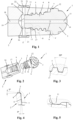
- FIG. 1 and 2 a tool arrangement with a screw-in tool 1 and an associated tool holder 2 is shown in a longitudinal section and a perspective view.
- the screw-in tool 1 has a tool head 3 embodied here as a spherical milling cutter and a tool shank 4 that tapers conically towards the rear and has an external thread 5 .
- a first support area with a first conical contact surface 6 for contact with a counter-conical bearing surface 7 is provided on a front face of the tool holder 2 and a second conical bearing surface 8 for bearing against a second conical bearing surface 9 inside the tool holder.
- a second support area 11 is located at a free rear end 10 of the tool shank 4.
- the tool head 3 has on its outside a plurality of wrench flats 12 distributed over the circumference for screwing the screw-in tool 1 into the tool holder 2 .
- the wrench flats 12 can also be used for automatic tool changes in the milling machine.
- a gripper groove 13 for automatically clamping the screw-in tool 1 in the tool holder 2 is also provided in the rear area of the tool shank 4 between the rear end of the external thread 5 and the rear second support area 11 .
- pliers-like gripper elements of a clamping device can engage in the gripper groove 13 in order to be able to securely grip or hold the screw-in tool 1 in the tool holder 2 .
- central through-opening 14 through which cooling lubricant, compressed air or another working fluid can be directed to the machining area.
- the passage opening 14 is arranged coaxially to the central axis 15 of the screwing tool 1, but other arrangements are also possible, for example with truly parallel or angled longitudinal axes.
- the tool holder 2 belonging to the screw-in tool 1 has a receiving opening 16 with an internal thread 17 .
- Radial bores 20 can also be arranged in the tool holder 2 , which open into the receiving opening 16 or also into the feed 19 .
- On the outside of the tool holder 2 a sleeve 22 provided with an annular groove 21 on the inside be arranged for an external coolant supply. However, the annular groove 21 can also be formed on the tool holder 2 .
- the external thread 5 of the screw-in tool 1 and the associated internal thread 17 of the tool holder 2 are trapezoidal threads with an in figure 3 illustrated flank angle of 30°.
- the external thread 5 of the screw-in tool 1 and the associated internal thread 17 of the tool holder 2 can also be designed as a trapezoidal thread with other flank angles.
- the external thread 5 used here has a thread depth that decreases from the tool head 3 to the free rear end 10 of the tool shaft 4 .
- the thread depth decreases from the second contact surface 9 to the second support area 11 .
- first contact surface 6 of the screw-in tool 1 and the corresponding first contact surface 7 of the tool holder 2 are each inclined by 5° with respect to a plane perpendicular to the central axes 15 and 18 in the direction of the front end of the tool head 3.
- first conical bearing surface 6 and also the first conical bearing surface 7 have a cone angle of at least 140° and at most 179°, but preferably 170°.
- the diameter of the second conical contact surface 8 of the screwing tool 1 and the diameter of the second conical contact surface 9 of the tool holder 2 taper in the screwing-in direction, resulting in a cone angle of at least 1° and a maximum of 90°, but preferably 10°, which results in an angle of Cone surfaces of 5 ° relative to the central axes 15 and 18 means.
- the second support area 11 of the screwing tool 1 is shown in FIG figure 5 spherical and comes into contact with a cylindrical contact surface 24 at the end of the receiving opening 16.
- the cylindrical contact surface 24 forms a further inner contact area in the tool holder.
- the spherical support area 11 ensures that there is only partial contact between the screw-in tool 1 and the tool holder 2.
- the spherical second support area 11 is expediently oversized compared to the cylindrical contact surface 24, so that the preload in this second support area is independent of the screw-in depth.
- FIG. 8 and 9 a further exemplary embodiment of a screw-in tool 1 and an associated tool holder 2 is shown.
- the external thread 5 of the screw-in tool 1 and the internal thread 17 of the tool holder 2 are designed as flat threads. Otherwise, this embodiment corresponds to the previous exemplary embodiment, so that components corresponding to one another are also provided with the same reference symbols.
- the external thread 5 used here has a thread depth that decreases from the tool head 3 to the free rear end 10 of the tool shank 4 . Furthermore, in the case of the internal thread 17 of the tool holder 2 , the thread depth also decreases here from the second contact surface 9 to the second support area 11 .
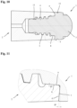
- FIG. 10 and 11 an exemplary embodiment is shown in which the diameter of the conical first contact surface 6 of the screwing tool 1 and the associated conical first contact surface 7 of the tool holder 2 increase in the screwing-in direction of the screwing tool 1 .
- the first contact surface 6 and the corresponding first support surface 7 are each inclined by 5° with respect to a plane perpendicular to the central axes 15 and 18 in the direction of the tool shank 4 .
- the first conical bearing surface 6 and also the first conical bearing surface 7 have exactly the same as in the exemplary embodiment 4 a cone angle of 170°.
- the second conical bearing surface 8 and the second conical bearing surface 9 taper at an angle of 5° in relation to the central axes 15 and 18, resulting in a cone angle of 10°.
- the cones on which the two conical surfaces forming the double cone are based point in opposite directions.
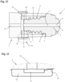
- an insert bushing 25 which contains the second conical bearing surface 9, the internal thread 17 and the cylindrical contact surface 24, is inserted into the receiving opening 16 of the tool holder 2.
- the radial bores 20 go through the tool holder 2 and the insert bushing 25 and open into the receiving opening 16 of the tool holder 2.
- FIG 13 shows an enlarged view of the sleeve 22 for the external coolant supply.
- the sleeve 22 has one or more outlets 26 through which the coolant guided outwards via the radial bores 20 and exiting through the outer openings 23 can be directed to the tool or the point to be machined.
- the outlet or outlets 26 can be designed as a circumferential gap, bores, slots or the like.
- the invention is not limited to the exemplary embodiments described above and illustrated in the drawing.
- the external coolant supply with the radial bores and the sleeve, the gripper groove for automatic clamping in a machine tool, the insert bush or the design of the tool holder made of fiber composite materials can be used individually or in combination with screw-in tools or tool holders, in which only simple conical , Cylindrical or flat contact or bearing surfaces or other centering or guiding options are used.
- These versions are not limited to screw-in tools or holders with a double cone.
Landscapes
- Engineering & Computer Science (AREA)
- Mechanical Engineering (AREA)
- Gripping On Spindles (AREA)
- Jigs For Machine Tools (AREA)
- Milling Processes (AREA)
- Details Of Spanners, Wrenches, And Screw Drivers And Accessories (AREA)
- Drilling Tools (AREA)
Applications Claiming Priority (3)
| Application Number | Priority Date | Filing Date | Title |
|---|---|---|---|
| DE102012100976.7A DE102012100976B4 (de) | 2012-02-07 | 2012-02-07 | Einschraubwerkzeug und Werkzeugaufnahme für ein derartiges Einschraubwerkzeug |
| EP13702395.8A EP2812142B1 (fr) | 2012-02-07 | 2013-01-23 | Outil à visser et logement d'outil pour un tel outil à visser |
| PCT/EP2013/051243 WO2013117431A1 (fr) | 2012-02-07 | 2013-01-23 | Outil à visser et logement d'outil pour un tel outil à visser |
Related Parent Applications (1)
| Application Number | Title | Priority Date | Filing Date |
|---|---|---|---|
| EP13702395.8A Division EP2812142B1 (fr) | 2012-02-07 | 2013-01-23 | Outil à visser et logement d'outil pour un tel outil à visser |
Publications (2)
| Publication Number | Publication Date |
|---|---|
| EP4234140A2 true EP4234140A2 (fr) | 2023-08-30 |
| EP4234140A3 EP4234140A3 (fr) | 2023-11-01 |
Family
ID=47633021
Family Applications (2)
| Application Number | Title | Priority Date | Filing Date |
|---|---|---|---|
| EP13702395.8A Active EP2812142B1 (fr) | 2012-02-07 | 2013-01-23 | Outil à visser et logement d'outil pour un tel outil à visser |
| EP23185867.1A Pending EP4234140A3 (fr) | 2012-02-07 | 2013-01-23 | Outil de vissage et logement d'outil pour un tel outil de vissage |
Family Applications Before (1)
| Application Number | Title | Priority Date | Filing Date |
|---|---|---|---|
| EP13702395.8A Active EP2812142B1 (fr) | 2012-02-07 | 2013-01-23 | Outil à visser et logement d'outil pour un tel outil à visser |
Country Status (16)
| Country | Link |
|---|---|
| US (1) | US9901989B2 (fr) |
| EP (2) | EP2812142B1 (fr) |
| JP (2) | JP6518065B2 (fr) |
| KR (2) | KR20140127844A (fr) |
| CN (1) | CN104093513B (fr) |
| BR (1) | BR112014019285B8 (fr) |
| CA (1) | CA2863269C (fr) |
| DE (1) | DE102012100976B4 (fr) |
| ES (1) | ES2959388T3 (fr) |
| MX (1) | MX357143B (fr) |
| MY (1) | MY171823A (fr) |
| PL (1) | PL2812142T3 (fr) |
| PT (1) | PT2812142T (fr) |
| RU (1) | RU2620426C2 (fr) |
| SG (1) | SG11201404550TA (fr) |
| WO (1) | WO2013117431A1 (fr) |
Families Citing this family (31)
| Publication number | Priority date | Publication date | Assignee | Title |
|---|---|---|---|---|
| US9827620B2 (en) * | 2010-09-29 | 2017-11-28 | Mitsubishi Materials Corporation | Head replacement-type cutting tool |
| DE102012100976B4 (de) * | 2012-02-07 | 2014-04-24 | Franz Haimer Maschinenbau Kg | Einschraubwerkzeug und Werkzeugaufnahme für ein derartiges Einschraubwerkzeug |
| DE102013100939A1 (de) * | 2013-01-30 | 2014-07-31 | Franz Haimer Maschinenbau Kg | Werkzeugaufnahme für ein Einschraubwerkzeug |
| US9643262B2 (en) | 2013-07-25 | 2017-05-09 | Kennametal Inc. | Coupling mechanism for cutting tool |
| US9643264B2 (en) | 2013-07-25 | 2017-05-09 | Kennametal Inc. | Coupling mechanism for cutting tool |
| DE202013008019U1 (de) | 2013-09-09 | 2013-09-26 | Peter Langbein | Dämpfungselemente für Werkzeugspannsysteme |
| KR102257817B1 (ko) * | 2014-04-11 | 2021-05-28 | 삼성전자 주식회사 | 전자장치에서 숫자의 입력을 제어하는 방법 및 장치 |
| US9889509B2 (en) | 2014-05-05 | 2018-02-13 | Kennametal Inc. | Cutter heads with improved coupling |
| DE102014214110A1 (de) * | 2014-07-21 | 2016-01-21 | Robert Bosch Gmbh | Hochdruckanschlussvorrichtung |
| CN104759649B (zh) * | 2015-04-28 | 2017-05-24 | 长沙矿山研究院有限责任公司 | 一种动力头钻杆锁紧机构 |
| TWI574762B (zh) * | 2015-05-20 | 2017-03-21 | Hsin Tien Chang | Tool connection of the thread structure |
| EP3308889A4 (fr) * | 2015-06-12 | 2019-01-09 | Mitsubishi Materials Corporation | Mèche d'extrémité effilée et tête de coupe |
| DE102015112080A1 (de) | 2015-07-24 | 2017-01-26 | Franz Haimer Maschinenbau Kg | Werkzeugaufnahme und Einschraubwerkzeug mit Dichtung |
| DE102015112079A1 (de) * | 2015-07-24 | 2017-01-26 | Franz Haimer Maschinenbau Kg | Einschraubwerkzeug und Werkzeugaufnahme mit unterteiltem Stützbereich |
| DE102015214434A1 (de) * | 2015-07-29 | 2017-02-02 | Franz Haimer Maschinenbau Kg | Rotierbares Zerspan-Werkzeug und Schlüssel hierfür |
| DE102015214432A1 (de) * | 2015-07-29 | 2017-02-02 | Franz Haimer Maschinenbau Kg | Rotierbares Zerspan-Werkzeug mit Axialsicherung für Schlüssel sowie Schlüssel |
| AT15013U1 (de) * | 2015-08-05 | 2016-11-15 | Ceratizit Austria Gmbh | Auswechselbarer Schneidkopf, Werkzeugschaft und Schaftwerkzeug |
| DE102015010399A1 (de) | 2015-08-11 | 2017-03-02 | Iscar Ltd. | Austauschbarer Schneidkopf, der einen Gewindeanbauabschnitt mit zwei beabstandeten konischen Anlageflächen hat, die mit dem gleichen Konuswinkel versehen sind, Werkzeughalter und rotierendes Schneidwerkzeug |
| US9844817B2 (en) | 2015-08-11 | 2017-12-19 | Iscar, Ltd. | Replaceable cutting head having threaded mounting portion with two spaced apart conical abutment surfaces provided with the same cone angle, tool holder and rotary cutting tool |
| DE102015116624B4 (de) | 2015-09-30 | 2023-06-15 | Haimer Gmbh | Schaftfräser |
| DE102015116623A1 (de) | 2015-09-30 | 2017-03-30 | Haimer Gmbh | Schaftfräser |
| US10105771B2 (en) * | 2016-03-21 | 2018-10-23 | Iscar, Ltd. | Rotary cutting tool having tool holder with conical internal thread and replaceable cutting head with straight external thread, and said tool holder |
| US10335871B2 (en) * | 2016-04-12 | 2019-07-02 | Iscar, Ltd. | Replaceable face-milling head with integrally formed threaded shank-connector |
| DE102016113373A1 (de) | 2016-07-20 | 2018-01-25 | Franz Haimer Maschinenbau Kg | Werkzeugsystem und Verbindungselement |
| DE102017121363A1 (de) | 2017-09-14 | 2019-03-14 | Franz Haimer Maschinenbau Kg | Gewindeeinsatz zur Befestigung eines Werkzeugs in einer Werkzeugaufnahme und Werkzeugaufnahme mit einem derartigen Gewindeeinsatz |
| JP7253649B2 (ja) * | 2017-10-12 | 2023-04-06 | 三菱鉛筆株式会社 | 筆記具 |
| JP7041486B2 (ja) * | 2017-10-12 | 2022-03-24 | 三菱鉛筆株式会社 | 筆記具 |
| US11446746B2 (en) | 2019-12-10 | 2022-09-20 | Iscar, Ltd. | Replaceable cutting head having back-tapered conical external thread and rotary cutting tool |
| US11376676B2 (en) | 2020-07-07 | 2022-07-05 | Iscar, Ltd. | Rotary cutting head having cutting edges extending past key actuating portion |
| US11426803B2 (en) | 2020-09-08 | 2022-08-30 | Iscar, Ltd. | Replaceable cutting head having external thread with concavely curved root and rotary cutting tool |
| DE102023132906A1 (de) * | 2023-11-24 | 2025-05-28 | Haimer Gmbh | Schaftfräser |
Citations (1)
| Publication number | Priority date | Publication date | Assignee | Title |
|---|---|---|---|---|
| WO2006033617A1 (fr) | 2004-09-24 | 2006-03-30 | Seco Tools Ab | Outil pour usinage d'evacuation de copeaux avec partie de filetage et partie de transition |
Family Cites Families (42)
| Publication number | Priority date | Publication date | Assignee | Title |
|---|---|---|---|---|
| US1569862A (en) | 1924-03-11 | 1926-01-19 | Francis J Lapointe | Broaching machine |
| US1749633A (en) | 1928-01-27 | 1930-03-04 | Lapointe Machine Tool Co | Machine for broaching spirals |
| US2060889A (en) | 1933-07-10 | 1936-11-17 | Colonial Broach Co | Broach |
| US2079692A (en) * | 1933-10-16 | 1937-05-11 | Francis J Lapointe | Broach shank connecter |
| FR1019411A (fr) * | 1950-06-02 | 1953-01-21 | Deragne Freres | Perfectionnement aux réaléseuses portatives |
| US2669468A (en) * | 1950-12-05 | 1954-02-16 | John W Clerke | Threaded joint and element thereof having improved thread form |
| GB848563A (en) * | 1956-06-09 | 1960-09-21 | Birmingham Small Arms Co Ltd | Improvements in or relating to chucks |
| US3087360A (en) * | 1960-07-19 | 1963-04-30 | Waldo L Garberding | Cutting tool having universal joint |
| US4192533A (en) * | 1976-04-22 | 1980-03-11 | Hydril Company | Dovetail connection for pin and box joints |
| SU1349887A1 (ru) * | 1985-05-22 | 1987-11-07 | Московский станкостроительный завод "Красный пролетарий" им.А.И.Ефремова | Наборный режущий инструмент |
| FR2602162B1 (fr) | 1986-08-01 | 1990-03-23 | Begue Pierre | Systeme de fixation d'un outil sur un organe porte-outil de machine-outil, parties constitutives |
| DD275638A1 (de) * | 1988-09-21 | 1990-01-31 | Schmalkalden Werkzeug | Spanneinrichtung fuer auswechselbare werkzeugkoepfe |
| DE59205930D1 (de) * | 1991-03-13 | 1996-05-15 | Polytool Ag | Reibahle mit auswechselbarem Schneidkopf |
| JPH05318208A (ja) * | 1992-05-16 | 1993-12-03 | Ngk Spark Plug Co Ltd | 回転切削工具 |
| SE509218C2 (sv) * | 1994-08-29 | 1998-12-21 | Sandvik Ab | Skaftverktyg |
| US5873687A (en) * | 1997-04-16 | 1999-02-23 | Mori Seiki Co., Ltd. | Tool unit with hydraulic feed passage |
| DE10009721A1 (de) * | 2000-03-01 | 2001-09-06 | Komet Stahlhalter Werkzeuge | Maschinenreibahle und Reibkopf für eine Maschinenreibahle |
| IL136032A (en) | 2000-05-09 | 2003-12-10 | Iscar Ltd | Tool joint |
| IL137316A (en) * | 2000-07-16 | 2004-01-04 | Iscar Ltd | Cutting Tools |
| US6565291B2 (en) * | 2000-08-18 | 2003-05-20 | Iscar, Ltd. | Cutting tool assembly |
| JP4610129B2 (ja) * | 2001-06-27 | 2011-01-12 | 京セラ株式会社 | ボールエンドミル |
| JP4378931B2 (ja) * | 2002-03-04 | 2009-12-09 | 三菱マテリアル株式会社 | 刃部交換式切削工具及びこれに装着される刃部 |
| IL150013A (en) * | 2002-06-04 | 2007-06-17 | Gil Hecht | Rotary cutting tool |
| SE526762C2 (sv) * | 2002-06-17 | 2005-11-01 | Sandvik Intellectual Property | Han/hon-koppling uppvisande presspassning mellan delarna |
| US7325471B2 (en) * | 2004-09-07 | 2008-02-05 | Kennametal Inc. | Toolholder and cutting insert for a toolholder assembly |
| SE528299C2 (sv) | 2004-09-24 | 2006-10-17 | Seco Tools Ab | Skärspets och skärverktyg med hållardel utformad som stympad konisk gänga |
| JP2006150509A (ja) * | 2004-11-30 | 2006-06-15 | Osg Corp | 切削工具 |
| US7694835B1 (en) * | 2005-01-04 | 2010-04-13 | Rexam Closures And Containers Inc. | Drafted neck finish having angled thread face and closure package |
| DE102005012025A1 (de) * | 2005-03-16 | 2006-12-07 | Heule, Ulf | Werkzeuganordnung mit männlichen und weiblichen Kupplungselementen |
| TW200924879A (en) | 2005-11-06 | 2009-06-16 | Iscar Ltd | Rotary cutting tool |
| SE530043C2 (sv) * | 2006-04-20 | 2008-02-12 | Sandvik Intellectual Property | Verktyg för spånavskiljande bearbetning samt del därtill |
| JP2008168386A (ja) * | 2007-01-11 | 2008-07-24 | Asahi Diamond Industrial Co Ltd | 回転工具 |
| DE102007012487B4 (de) * | 2007-03-15 | 2016-12-15 | Franz Haimer Maschinenbau Kg | Werkzeughalter |
| SE532394C2 (sv) * | 2007-06-04 | 2010-01-12 | Sandvik Intellectual Property | Verktyg för spånavskiljande bearbetning samt grundkropp härför |
| DE112007003740T5 (de) * | 2007-12-27 | 2010-11-04 | OSG Corp., Toyokawa-shi | Karbidrotationswerkzeug |
| DE102009042395A1 (de) * | 2009-09-16 | 2011-03-24 | Hartmetall-Werkzeugfabrik Paul Horn Gmbh | Reibwerkzeug zur spanenden Bearbeitung eines Werkstücks |
| DE102009048010B3 (de) * | 2009-10-02 | 2011-02-17 | Kennametal Inc. | Werkzeuginterface |
| DE102010028561A1 (de) * | 2010-05-04 | 2011-11-10 | Helmut Diebold Gmbh & Co. Goldring-Werkzeugfabrik | Werkzeugaufnahme |
| US9827620B2 (en) | 2010-09-29 | 2017-11-28 | Mitsubishi Materials Corporation | Head replacement-type cutting tool |
| DE102011010897B4 (de) | 2011-02-10 | 2023-02-09 | Gebr. Brasseler Gmbh & Co. Kg | Dentalinstrument sowie Verfahren zu dessen Herstellung |
| AT13405U1 (de) | 2012-01-20 | 2013-12-15 | Ceratizit Austria Gmbh | Hartwerkstoff-gewindeverbindung |
| DE102012100976B4 (de) * | 2012-02-07 | 2014-04-24 | Franz Haimer Maschinenbau Kg | Einschraubwerkzeug und Werkzeugaufnahme für ein derartiges Einschraubwerkzeug |
-
2012
- 2012-02-07 DE DE102012100976.7A patent/DE102012100976B4/de not_active Revoked
-
2013
- 2013-01-23 JP JP2014555993A patent/JP6518065B2/ja active Active
- 2013-01-23 MX MX2014009467A patent/MX357143B/es active IP Right Grant
- 2013-01-23 CA CA2863269A patent/CA2863269C/fr active Active
- 2013-01-23 ES ES13702395T patent/ES2959388T3/es active Active
- 2013-01-23 WO PCT/EP2013/051243 patent/WO2013117431A1/fr not_active Ceased
- 2013-01-23 BR BR112014019285A patent/BR112014019285B8/pt active IP Right Grant
- 2013-01-23 SG SG11201404550TA patent/SG11201404550TA/en unknown
- 2013-01-23 PT PT137023958T patent/PT2812142T/pt unknown
- 2013-01-23 US US14/376,738 patent/US9901989B2/en active Active
- 2013-01-23 KR KR1020147024577A patent/KR20140127844A/ko not_active Ceased
- 2013-01-23 KR KR1020167034106A patent/KR101965173B1/ko active Active
- 2013-01-23 RU RU2014133094A patent/RU2620426C2/ru active
- 2013-01-23 CN CN201380007901.7A patent/CN104093513B/zh active Active
- 2013-01-23 EP EP13702395.8A patent/EP2812142B1/fr active Active
- 2013-01-23 EP EP23185867.1A patent/EP4234140A3/fr active Pending
- 2013-01-23 MY MYPI2014702159A patent/MY171823A/en unknown
- 2013-01-23 PL PL13702395.8T patent/PL2812142T3/pl unknown
-
2016
- 2016-12-27 JP JP2016252366A patent/JP6798875B2/ja active Active
Patent Citations (1)
| Publication number | Priority date | Publication date | Assignee | Title |
|---|---|---|---|---|
| WO2006033617A1 (fr) | 2004-09-24 | 2006-03-30 | Seco Tools Ab | Outil pour usinage d'evacuation de copeaux avec partie de filetage et partie de transition |
Also Published As
| Publication number | Publication date |
|---|---|
| JP6798875B2 (ja) | 2020-12-09 |
| RU2620426C2 (ru) | 2017-05-25 |
| EP2812142A1 (fr) | 2014-12-17 |
| PT2812142T (pt) | 2023-10-04 |
| ES2959388T3 (es) | 2024-02-26 |
| KR20160148031A (ko) | 2016-12-23 |
| MX357143B (es) | 2018-06-28 |
| CN104093513B (zh) | 2018-01-26 |
| BR112014019285A8 (pt) | 2017-07-11 |
| WO2013117431A1 (fr) | 2013-08-15 |
| JP6518065B2 (ja) | 2019-05-22 |
| MY171823A (en) | 2019-10-31 |
| SG11201404550TA (en) | 2014-11-27 |
| PL2812142T3 (pl) | 2024-03-04 |
| DE102012100976B4 (de) | 2014-04-24 |
| BR112014019285B8 (pt) | 2022-11-22 |
| BR112014019285A2 (fr) | 2017-06-20 |
| EP2812142B1 (fr) | 2023-07-26 |
| EP4234140A3 (fr) | 2023-11-01 |
| US20150016905A1 (en) | 2015-01-15 |
| KR20140127844A (ko) | 2014-11-04 |
| DE102012100976A1 (de) | 2013-08-08 |
| BR112014019285B1 (pt) | 2022-02-15 |
| MX2014009467A (es) | 2015-03-19 |
| RU2014133094A (ru) | 2016-03-27 |
| KR101965173B1 (ko) | 2019-04-03 |
| JP2017104976A (ja) | 2017-06-15 |
| CA2863269A1 (fr) | 2013-08-15 |
| JP2015509854A (ja) | 2015-04-02 |
| CA2863269C (fr) | 2017-09-12 |
| US9901989B2 (en) | 2018-02-27 |
| CN104093513A (zh) | 2014-10-08 |
Similar Documents
| Publication | Publication Date | Title |
|---|---|---|
| EP2812142B1 (fr) | Outil à visser et logement d'outil pour un tel outil à visser | |
| EP2885094B1 (fr) | Ensemble d'outil | |
| EP2950955B1 (fr) | Porte-outil pour un outil pourvu d'une tige à filetage extérieur | |
| EP2855058B1 (fr) | Raccordement d'outil à visser | |
| DE102006062973C5 (de) | System aus Werkzeughalter mit einer zylindrischen Werkzeugaufnahme in Form eines Spannzangenfutters und Werkzeug | |
| DE102007012487B4 (de) | Werkzeughalter | |
| DE102011101096A1 (de) | Bolzen und Spannsystem mit Bolzen | |
| CH656335A5 (de) | Bohrwerkzeug. | |
| EP2266732B1 (fr) | Système de serrage | |
| DE3912503A1 (de) | Spanneinrichtung fuer auswechselbare werkzeugkoepfe | |
| EP3512657B1 (fr) | Système d'outil | |
| DE102015119060B3 (de) | Spannvorrichtung | |
| EP3016770B1 (fr) | Système de tête interchangeable pour l'usinage de métaux | |
| DE202015101365U1 (de) | Spannfutter | |
| DE202007014828U1 (de) | Spannfutter für zu spannende Teile | |
| DE102015207955A1 (de) | Spannfutter | |
| EP3191258B1 (fr) | Système d'outils et porte-outils | |
| DE20105764U1 (de) | Vorrichtung zum Bearbeiten von Werkstücken | |
| DE102016113373A1 (de) | Werkzeugsystem und Verbindungselement | |
| EP3043938B1 (fr) | Outil de coupe | |
| DE3700841A1 (de) | Kupplungselement, insbesondere zum kraft- und formschluessigen verbinden eines werkzeugkopfes mit einem werkzeugtraeger | |
| DE20112508U1 (de) | Kupplungsvorrichtung für das Verbinden einer Spindel mit einem Werkzeughalter | |
| DE102021106246A1 (de) | Mehrteiliges, modulares Werkzeug |
Legal Events
| Date | Code | Title | Description |
|---|---|---|---|
| PUAI | Public reference made under article 153(3) epc to a published international application that has entered the european phase |
Free format text: ORIGINAL CODE: 0009012 |
|
| STAA | Information on the status of an ep patent application or granted ep patent |
Free format text: STATUS: THE APPLICATION HAS BEEN PUBLISHED |
|
| AC | Divisional application: reference to earlier application |
Ref document number: 2812142 Country of ref document: EP Kind code of ref document: P |
|
| AK | Designated contracting states |
Kind code of ref document: A2 Designated state(s): AL AT BE BG CH CY CZ DE DK EE ES FI FR GB GR HR HU IE IS IT LI LT LU LV MC MK MT NL NO PL PT RO RS SE SI SK SM TR |
|
| REG | Reference to a national code |
Ref country code: DE Ref legal event code: R079 Free format text: PREVIOUS MAIN CLASS: B23C0005260000 Ipc: B23B0031110000 |
|
| PUAL | Search report despatched |
Free format text: ORIGINAL CODE: 0009013 |
|
| AK | Designated contracting states |
Kind code of ref document: A3 Designated state(s): AL AT BE BG CH CY CZ DE DK EE ES FI FR GB GR HR HU IE IS IT LI LT LU LV MC MK MT NL NO PL PT RO RS SE SI SK SM TR |
|
| RIC1 | Information provided on ipc code assigned before grant |
Ipc: B23C 5/10 20060101ALI20230927BHEP Ipc: B23B 31/11 20060101AFI20230927BHEP |
|
| STAA | Information on the status of an ep patent application or granted ep patent |
Free format text: STATUS: REQUEST FOR EXAMINATION WAS MADE |
|
| 17P | Request for examination filed |
Effective date: 20240423 |
|
| RBV | Designated contracting states (corrected) |
Designated state(s): AL AT BE BG CH CY CZ DE DK EE ES FI FR GB GR HR HU IE IS IT LI LT LU LV MC MK MT NL NO PL PT RO RS SE SI SK SM TR |