EP4234857B1 - Ensemble poignée de portière de véhicule comportant un mécanisme de secours - Google Patents
Ensemble poignée de portière de véhicule comportant un mécanisme de secours Download PDFInfo
- Publication number
- EP4234857B1 EP4234857B1 EP22158288.5A EP22158288A EP4234857B1 EP 4234857 B1 EP4234857 B1 EP 4234857B1 EP 22158288 A EP22158288 A EP 22158288A EP 4234857 B1 EP4234857 B1 EP 4234857B1
- Authority
- EP
- European Patent Office
- Prior art keywords
- handle grip
- flap
- vehicle door
- handle assembly
- door handle
- Prior art date
- Legal status (The legal status is an assumption and is not a legal conclusion. Google has not performed a legal analysis and makes no representation as to the accuracy of the status listed.)
- Active
Links
Images



Classifications
-
- E—FIXED CONSTRUCTIONS
- E05—LOCKS; KEYS; WINDOW OR DOOR FITTINGS; SAFES
- E05B—LOCKS; ACCESSORIES THEREFOR; HANDCUFFS
- E05B85/00—Details of vehicle locks not provided for in groups E05B77/00 - E05B83/00
- E05B85/10—Handles
- E05B85/103—Handles creating a completely closed wing surface
-
- E—FIXED CONSTRUCTIONS
- E05—LOCKS; KEYS; WINDOW OR DOOR FITTINGS; SAFES
- E05B—LOCKS; ACCESSORIES THEREFOR; HANDCUFFS
- E05B85/00—Details of vehicle locks not provided for in groups E05B77/00 - E05B83/00
- E05B85/10—Handles
-
- E—FIXED CONSTRUCTIONS
- E05—LOCKS; KEYS; WINDOW OR DOOR FITTINGS; SAFES
- E05B—LOCKS; ACCESSORIES THEREFOR; HANDCUFFS
- E05B77/00—Vehicle locks characterised by special functions or purposes
- E05B77/42—Means for damping the movement of lock parts, e.g. slowing down the return movement of a handle
-
- E—FIXED CONSTRUCTIONS
- E05—LOCKS; KEYS; WINDOW OR DOOR FITTINGS; SAFES
- E05B—LOCKS; ACCESSORIES THEREFOR; HANDCUFFS
- E05B79/00—Mounting or connecting vehicle locks or parts thereof
- E05B79/02—Mounting of vehicle locks or parts thereof
- E05B79/06—Mounting of handles, e.g. to the wing or to the lock
-
- E—FIXED CONSTRUCTIONS
- E05—LOCKS; KEYS; WINDOW OR DOOR FITTINGS; SAFES
- E05B—LOCKS; ACCESSORIES THEREFOR; HANDCUFFS
- E05B79/00—Mounting or connecting vehicle locks or parts thereof
- E05B79/10—Connections between movable lock parts
- E05B79/20—Connections between movable lock parts using flexible connections, e.g. Bowden cables
-
- E—FIXED CONSTRUCTIONS
- E05—LOCKS; KEYS; WINDOW OR DOOR FITTINGS; SAFES
- E05B—LOCKS; ACCESSORIES THEREFOR; HANDCUFFS
- E05B79/00—Mounting or connecting vehicle locks or parts thereof
- E05B79/10—Connections between movable lock parts
- E05B79/22—Operative connections between handles, sill buttons or lock knobs and the lock unit
-
- E—FIXED CONSTRUCTIONS
- E05—LOCKS; KEYS; WINDOW OR DOOR FITTINGS; SAFES
- E05B—LOCKS; ACCESSORIES THEREFOR; HANDCUFFS
- E05B81/00—Power-actuated vehicle locks
- E05B81/54—Electrical circuits
- E05B81/64—Monitoring or sensing, e.g. by using switches or sensors
- E05B81/76—Detection of handle operation; Detection of a user approaching a handle; Electrical switching actions performed by door handles
-
- E—FIXED CONSTRUCTIONS
- E05—LOCKS; KEYS; WINDOW OR DOOR FITTINGS; SAFES
- E05B—LOCKS; ACCESSORIES THEREFOR; HANDCUFFS
- E05B81/00—Power-actuated vehicle locks
- E05B81/54—Electrical circuits
- E05B81/90—Manual override in case of power failure
-
- E—FIXED CONSTRUCTIONS
- E05—LOCKS; KEYS; WINDOW OR DOOR FITTINGS; SAFES
- E05B—LOCKS; ACCESSORIES THEREFOR; HANDCUFFS
- E05B85/00—Details of vehicle locks not provided for in groups E05B77/00 - E05B83/00
- E05B85/10—Handles
- E05B85/107—Pop-out handles, e.g. sliding outwardly before rotation
-
- E—FIXED CONSTRUCTIONS
- E05—LOCKS; KEYS; WINDOW OR DOOR FITTINGS; SAFES
- E05B—LOCKS; ACCESSORIES THEREFOR; HANDCUFFS
- E05B85/00—Details of vehicle locks not provided for in groups E05B77/00 - E05B83/00
- E05B85/10—Handles
- E05B85/14—Handles pivoted about an axis parallel to the wing
- E05B85/16—Handles pivoted about an axis parallel to the wing a longitudinal grip part being pivoted at one end about an axis perpendicular to the longitudinal axis of the grip part
-
- E—FIXED CONSTRUCTIONS
- E05—LOCKS; KEYS; WINDOW OR DOOR FITTINGS; SAFES
- E05B—LOCKS; ACCESSORIES THEREFOR; HANDCUFFS
- E05B81/00—Power-actuated vehicle locks
Definitions
- the present invention relates to the field of vehicle door handles, in particular of the type with a flushing door handle grip.
- vehicle door handle assemblies generally comprise an electric motor which, when actuated, moves the handle grip between a flush position in which the handle grip is flush with an exterior door panel surface and a ready position in which said handle grip is protruding and graspable by a user.
- the flush position the handle grip is flush with the exterior surface of the door body.
- the air drag of the vehicle can consequently be reduced, while the visual aspect of the vehicle can be streamlined.
- the handle grip is protruding from said exterior surface, so as to be graspable by a user. The user can seize the handle and pull on it in order to unlock and/or open the vehicle door.
- Such vehicle door handle assemblies generally comprise a back-up mechanism, to enable the opening of the door in case of, for example, electric motor or car battery failure, that is when the electric motor cannot be actuated.
- This back-up mechanism comprises for example a push-push mechanism, in which the user pushes the handle grip inwards from its flushing position until reaching a clicking position in which a preloaded spring is released. Said preloaded spring, when released, pushes the handle grip from the inward clicking position in the protruding ready position.
- Such a back-up mechanism may comprise an important number of elements, which occupy an important space inside the handle. Consequently, there is a need for a simple, compact architecture of the back-up mechanism for the vehicle door handle that enables a user to easily interact with said handle in case of an electric motor or car battery failure.
- document KR 102 104 888 B1 discloses a vehicle door handle assembly according to the preamble of claim 1.
- the present invention refers to a vehicle door handle assembly comprising a handle grip which is movable between a flushing position in which it is flush with an exterior door panel surface and a ready position in which it is protruding and graspable by a user, wherein the vehicle door handle assembly also comprises a back-up mechanism that enables a user to easily interact with said handle in case of an electric motor or car battery failure, said back-up mechanism comprising a flap covering at least partially a cavity arranged inside the handle grip, the flap being movable between a closed position in which it covers the cavity inside the handle grip and an open position in which it permits access to the inside of said cavity, hence allowing a user to insert his fingers or an object inside the cavity and to pull on the handle grip in order to move it from the flushing position into the ready position, characterized in that the flap is movable around a pivot axis located on an edge of the cavity arranged inside the handle grip.
- the vehicle door handle assembly according to the invention may present one or more of the following dependent characteristics, taken separately or in combination.
- the vehicle door handle assembly comprises an elastic return element configured to move the flap from the open position back into the closed position.
- the cavity and the flap are located in a middle section of the handle grip.
- the flap has a different colour than the handle grip.
- At least a portion of the external surface of the flap has a different texture to the touch than the handle grip.
- the vehicle door handle assembly comprises a bracket which is linked to the handle grip and the bracket comprises a stopper mechanism for adjusting the position of the handle grip in the flush position.
- the stopper mechanism comprises a contact surface that is intended to make contact with a portion of the handle grip in order to adjust the position of the handle grip in the flush position.
- the stopper mechanism comprises a housing, an elastic return element and a cap.
- the housing and the cap present a geometry of revolution.
- An XYZ trihedron is shown in some figures to define the orientation of the handle grip in space.
- a first direction, noted X corresponds to a longitudinal direction of the handle grip.
- a second direction, denoted Y is directed to the inner side of the vehicle door handle assembly.
- a third direction, denoted Z points towards a general upward direction.
- the directions, X, Y, Z are orthogonal to each other.
- the terms up, upper, low, lower, vertical, horizontal refer to relative positions or directions when the door handle is assembled to a vehicle.
- certain items can be indexed, as the first item or second item. In this case, it is a simple indexing to differentiate and name similar but not identical elements. This indexing does not imply a priority of one element over another and such names can easily be interchanged without going beyond the scope of the present description. Nor does this indexing imply an order in time.
- Fig. 1 shows a vehicle door handle assembly comprising a bracket 2 located on the inner side of the vehicle door and a handle grip 3 which is linked to the bracket 2.
- the handle grip 3 is in a flushing position in which it is flush with an exterior door panel surface.
- the handle grip 3 of the vehicle door handle assembly is also linked to an electric motor (not illustrated) which, when actuated, moves the handle grip 3 between the flush position and a ready position in which the handle grip 3 is protruding and graspable by a user.
- the motor can push one end of the handle grip 3 in an outward direction. In that case, the handle grip 3 is moved around a substantially vertical axis.
- the ready position is not shown in the figures.
- the user can grasp said handle grip 3 and unlatch the door by pulling it in a further protruding unlocking position, in which the handle grip 3 interacts (via a Bowden cable, a rotating pin or a gear mechanism) with a latch mechanism and unlatches the door.
- the handle grip 3 is for example made of two half-shells 3a, 3b that are assembled together.
- the assembled handle grip 3 is hence at least partially hollow inside.
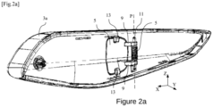
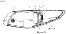
- Fig.1 shows the exterior surface of the outer shell 3a and Figs. 2a and 2b show the inner side of this same outer shell 3a.
- An assembled version of the handle grip 3 comprising both the outer shell 3a and the inner shell 3b is shown in Fig.5 .
- the vehicle door handle assembly also comprises a back-up mechanism which enables a user to manually move the handle grip 3 between the flushing position and the ready position in case of an electric failure, such as a battery failure.
- This back-up mechanism comprises a flap 5 which covers at least partially a cavity arranged inside the handle grip 3.
- the outer shell 3a of the handle grip 3 has a hole 7. Said hole 7 marks the entrance to the cavity arranged inside the handle grip 3.
- the cavity arranged inside the handle grip 3 and the flap 5 are located in a middle section of the handle grip 3.
- the cavity and the flap 5 might be located elsewhere, but in the middle section of the handle grip 3 they are easier to spot and easier to use if needed.
- the flap 5 is movable between a closed position ( Fig.2a ) and an open position ( Fig. 2b ).
- the flap 5 covers the cavity inside the handle grip 3, meaning that the edges of the flap 5 correspond to the contours of the hole 7.
- the outer surface of the flap 5 is flush with the outer surface of the outer shell 3a of the handle grip 3 when the flap is in the closed position.
- the flap 5 When the flap 5 is in the open position, it permits access to the inside of the cavity, hence allowing a user to insert his fingers or an object, like a hook or a key for instance, inside the cavity and to pull on the handle grip 3 in order to move it from the flushing position to the ready position. For instance, the user can curl his fingers around an edge of the hole 7 and pull on said edge in order to move the handle grip 3 from the flush position into the ready position in case of an electric failure.
- a pulling element can be located inside the cavity. A user can pull on this pulling element with his fingers or with an object in order to move the handle grip 3 from the flush position into the ready position.
- the flap 5 is movable around a pivot axis P located on an edge of the cavity arranged inside the handle grip 3, as it is shown in figure 2a and 2b .
- This pivot axis P can be parallel to the vertical direction Z. Other directions, like a horizontal direction for instance, can also be considered.
- the pivot axis P can be located on a side of the hole 7 arranged in the outer half-shell 3a of the handle grip 3.
- the pivot axis P may be parallel to the axis around which the handle grip 3 is rotated by the electric motor when said handle grip 3 is moved from the flush position to a ready position.
- the pivot axis P is located on the edge of the hole 7 that is the closest to the end of the handle grip 3 that is not being pushed by the electric motor. Such an arrangement of the pivot axes facilitates the movement of the various parts, especially the flap 5 and the handle grip 3, and increases efficiency during handling.
- the flap 5 may comprise at least one hinge 9 configured to cooperate with a rod 11 that is aligned with the pivot axis P.
- the flap 5 comprises two distinct hinges 9.
- the flap 5 and the pivot axis P may be arranged in such a way that in order to reach the open position, the flap 5 must be moved inwards. A simple push on the exterior side of the flap 5 can hence be enough to move it from the closed position into the open position. In the open position, the flap 5 is then located inside the cavity of the handle grip 3.
- the flap 5 comprises at least one stopper 13 arranged on the inner side of the flap 5.
- two stoppers 13 are arranged on the upper and lower edges of the flap 5.
- the stoppers 13 are for example located in the middle of said upper and lower edges and project over said edges of the flap 5 so that when the latter is in the closed position, the stoppers 13 rest against the inner surface of the outer shell 3a of the handle grip 3.
- the stoppers 13 serve to position the flap 5 in its closed position: they prevent the flap 5 from protruding outwards from the handle grip 3.
- the stoppers 13 have a generally square shape, but any other shape is possible for these stoppers 13, such as a rectangular shape, a circular shape or a half-moon shape.
- the flap 5 may comprise a single stopper 13 located, for example, in the middle of the edge opposite the edge equipped with the hinge or hinges 9.
- the flap 5 and the pivot axis P around which the flap 5 rotates can be arranged in such a way that the flap 5 protrudes from the outside surface of the outer shell 3a of the handle grip 3 when the flap 5 is in the open position.
- the flap 5 may be used as an additional pulling element for moving the handle grip 3 from the flush position into the ready position.
- the flap 5 does not comprise the stoppers 13 described earlier.
- the back-up mechanism can also comprise an elastic return element 15 configured to move the flap 5 from the open position back into the closed position.
- the elastic return element 15 is a helical spring with coils that are arranged around the rod 11 that is aligned with the pivot axis P. More specifically, the helical spring can be located between the two hinges 9 of the flap 5.
- one end of the elastic return element 15 is attached to the flap 5 while the other end of the elastic return element 15 is attached to another part of the vehicle door handle assembly.
- Such an elastic return element 15 ensures that the flap 5 is moved back into the closed position even if the user makes little effort to put the flap 5 back in the original position after it has served its purpose.
- the elastic return element 15 also ensures that the flap 5 doesn't move freely when the car is used (acceleration, turns, shifts, slope change, ).
- the flap 5 can have a different colour than the handle grip 3, making it easier to spot when searching for the cavity said flap 5 covers.
- the handle grip 3 can have a light colour and the flap 5 a dark colour, or vice-versa.
- the external surface of the flap 5 can have a different texture to the touch than the handle grip 3.
- the handle grip 3 can have a smooth surface while at least a portion of the external surface of the flap 5 can have a rough surface. This way the flap 5 can be easily found by touch and used even in the absence of light, by night for example.
- the contour of the flap 5 may be illuminated to enable it to be delineated from the rest of the handle grip 3 in the absence of light, by night for example.
- the flap 5 can be slid from the closed position in which it covers the cavity inside the handle grip 3 into the open position in which it gives access to the cavity.
- the flap is not pivoted around an axis, but slid sideways in a translational movement along the longitudinal direction of the handle grip 3, for example.
- the bracket 2 of the vehicle door handle assembly 1 can be equipped with a stopper mechanism 17 for adjusting the position of the handle grip 3 in the flush position after it has been used.
- stopper mechanism 17 can also be used to adjust the flush position of the handle grip 3 even when the handle grip 3 is new or first installed.
- the mechanism can enable the flush position by itself or be a solution to compensate for a deviation as described.
- the stopper mechanism 17 does this by making contact with a specific portion of the handle grip 3 whenever the latter is moved back into the flush position.
- the inner half-shell 3b of the handle grip 3 can comprise a bent portion 31 on each of its longitudinal endings, such as illustrated in Fig. 5 . These bent portions 31 are usually used to guide the handle grip 3 in translation when it is moved from the flush position into the ready position.
- one of the bent portions of the inner half-shell 3b of the handle grip 3 also serves another purpose.
- the tip 27 of said bent portion 31 comes into contact with a surface of the stopper mechanism 17 in order to repeatedly adjust the position of the handle grip 3 in the flush position, as shown in Figure 5 .
- the stopper mechanism 17 helps to adjust an exact and reliable position of the handle grip 3 every time it is moved back into the flush position.
- the stopper mechanism 17 comprises a housing 19, an elastic return element 21 and a cap 23. It's the cap 23 that comes into contact with the tip 27 of the bent portion 31 of the inner half-shell 3b of the handle grip 3.
- the housing 19, the elastic return element 21 and the cap 23 are stacked on top of each other along an assembly axis A shown in figure 6 .
- At least a portion of the elastic return element 21 is located inside the housing 19 and at least a portion of the cap 23 is also arranged inside the housing 19.
- a portion of the elastic return element 21 can peak out of the housing 19, as shown in figure 6 .
- the cap 23 has a mostly longitudinal shape.
- One end of the cap 23 comprises a flat surface 25 that is shaped like a disk. This disk-shaped flat surface 25 is intended to make contact with the tip 27 of the bent portion of the inner half-shell 3a of the handle grip 3 in order to adjust the flush position of said handle grip 3.
- the housing 19 can have a geometry of revolution and present for instance an overall cylindrical shape.
- the inside of the housing 19 can present an overall cylindrical shape.
- the end of the housing 19 located on the opposite side of the disk-shaped flat surface 25 of the cap 23 may comprise a hexagonal-shaped head, as shown in Figures 5 and 6 .
- the elastic return element 21 can have the form of a helical spring that is arranged inside the cylindrical opening of the housing 19.
- the elastic return element 21 is rigid enough to withstand the force that will be received from the handle grip 3 when the latter is being moved.
- part of the coils of this elastic return element 21 can be arranged around the rod-shaped middle section of the cap 23.
- the tip of this rod-shaped middle section can comprise an enlarged section 29 configured to retain the spring coils of the elastic return element 21 around said middle section.
- the enlarged section 29 of the rod-shaped middle section of the cap 23 is stored inside the cylindrical opening of the housing 19.
- the flap 5 and the stopper mechanism 17 can work independently of each other. In case one of these features is deficient, it is possible to replace only the deficient part without having to replace the entire back-up mechanism.
Landscapes
- Lock And Its Accessories (AREA)
Claims (9)
- Ensemble poignée de portière de véhicule (1), comprenant une partie de préhension de poignée (3) qui est mobile entre une position à ras, dans laquelle elle est au ras d'une surface de panneau de portière extérieure, et une position prête dans laquelle elle est saillante et saisissable par un utilisateur, dans lequel l'ensemble poignée de portière de véhicule (1) comprend un mécanisme de secours pour un ensemble poignée de portière de véhicule qui permet à un utilisateur d'interagir facilement avec ladite poignée en cas d'une défaillance de moteur électrique ou de batterie de voiture, ledit mécanisme de secours comprenant un clapet (5) couvrant au moins partiellement une cavité agencée à l'intérieur de la partie de préhension de poignée (3), le clapet (5) étant mobile entre une position fermée dans laquelle il couvre la cavité à l'intérieur de la partie de préhension de poignée (3) et une position ouverte dans laquelle il autorise l'accès à la partie intérieure de ladite cavité, ainsi permettant à un utilisateur d'insérer ses doigts ou un objet à l'intérieur de la cavité et de tirer sur la partie de préhension de poignée (3) afin de déplacer la partie de préhension de poignée (3) de la position à ras à la position prête, caractérisé en ce que le clapet (5) est mobile autour d'un axe de pivotement (P) situé sur un bord de la cavité agencé à l'intérieur de la partie de préhension de poignée (3).
- Ensemble poignée de portière de véhicule selon la revendication 1, comprenant un élément de rappel élastique (15) configuré pour déplacer le clapet (5) de la position ouverte de retour dans la position fermée.
- Ensemble poignée de portière de véhicule selon une quelconque des revendications précédentes, dans lequel la cavité et le clapet (5) sont situés dans une section médiane de la partie de préhension de poignée (3).
- Ensemble poignée de portière de véhicule selon une quelconque des revendications précédentes, dans lequel le clapet (5) a une couleur différente de celle de la partie de préhension de poignée (3).
- Ensemble poignée de portière de véhicule selon une quelconque des revendications précédentes, dans lequel au moins une portion de la surface externe du clapet (5) a une texture au toucher différente de celle de la partie de préhension de poignée (3).
- Ensemble poignée de portière de véhicule selon une quelconque des revendications précédentes, comprenant un support (2) qui est lié à la partie de préhension de poignée (3), le support (2) comprenant un mécanisme de butée (17) pour ajuster la position de la partie de préhension de poignée (3) dans la position à ras.
- Ensemble poignée de portière de véhicule selon la revendication 6, dans lequel le mécanisme de butée (17) comprend une surface de contact qui est prévue pour entrer en contact avec une portion de la partie de préhension de poignée (3) afin d'ajuster la position de la partie de préhension de poignée (3) dans la position à ras.
- Ensemble poignée de portière de véhicule selon l'une quelconque des revendications 6 et 7, dans lequel le mécanisme de butée (17) comprend un logement (19), un élément de rappel élastique (21) et un capuchon (23).
- Ensemble poignée de portière de véhicule selon la revendication 8, dans lequel le logement (19) et le capuchon (23) ont une géométrie de révolution.
Priority Applications (5)
| Application Number | Priority Date | Filing Date | Title |
|---|---|---|---|
| EP22158288.5A EP4234857B1 (fr) | 2022-02-23 | 2022-02-23 | Ensemble poignée de portière de véhicule comportant un mécanisme de secours |
| JP2023014594A JP2023122626A (ja) | 2022-02-23 | 2023-02-02 | バックアップ機構付き車両用ドアハンドルアセンブリ |
| CN202310146513.2A CN116641606A (zh) | 2022-02-23 | 2023-02-21 | 具有备用机构的车门把手组件 |
| KR1020230023581A KR20230126661A (ko) | 2022-02-23 | 2023-02-22 | 백업 메커니즘을 갖는 차량 도어 핸들 조립체 |
| US18/173,369 US12331566B2 (en) | 2022-02-23 | 2023-02-23 | Vehicle door handle assembly with back-up mechanism |
Applications Claiming Priority (1)
| Application Number | Priority Date | Filing Date | Title |
|---|---|---|---|
| EP22158288.5A EP4234857B1 (fr) | 2022-02-23 | 2022-02-23 | Ensemble poignée de portière de véhicule comportant un mécanisme de secours |
Publications (2)
| Publication Number | Publication Date |
|---|---|
| EP4234857A1 EP4234857A1 (fr) | 2023-08-30 |
| EP4234857B1 true EP4234857B1 (fr) | 2024-09-25 |
Family
ID=80448530
Family Applications (1)
| Application Number | Title | Priority Date | Filing Date |
|---|---|---|---|
| EP22158288.5A Active EP4234857B1 (fr) | 2022-02-23 | 2022-02-23 | Ensemble poignée de portière de véhicule comportant un mécanisme de secours |
Country Status (5)
| Country | Link |
|---|---|
| US (1) | US12331566B2 (fr) |
| EP (1) | EP4234857B1 (fr) |
| JP (1) | JP2023122626A (fr) |
| KR (1) | KR20230126661A (fr) |
| CN (1) | CN116641606A (fr) |
Families Citing this family (3)
| Publication number | Priority date | Publication date | Assignee | Title |
|---|---|---|---|---|
| US20240076915A1 (en) * | 2022-08-30 | 2024-03-07 | Magna Mirrors Of America, Inc. | Vehicular closure opening device with push to actuate function |
| USD1028818S1 (en) * | 2022-10-18 | 2024-05-28 | Shenzhen Zhengtu Auto Accessories Co., Ltd. | Set of car interior door handle covers |
| CN121889910A (zh) | 2023-09-21 | 2026-04-17 | 株式会社Lg新能源 | 电池模块 |
Family Cites Families (12)
| Publication number | Priority date | Publication date | Assignee | Title |
|---|---|---|---|---|
| US8786401B2 (en) * | 2009-12-23 | 2014-07-22 | Magna Mirrors Of America, Inc. | Extendable flush door handle for vehicle |
| DE102013112120A1 (de) * | 2013-11-04 | 2015-05-07 | Kiekert Aktiengesellschaft | Kraftfahrzeugtürverschluss |
| DE102014112887A1 (de) * | 2014-09-08 | 2016-03-10 | Huf Hülsbeck & Fürst Gmbh & Co. Kg | Türaußengriff für Kraftfahrzeug |
| EP3020895B1 (fr) * | 2014-11-13 | 2017-11-15 | Huf Hülsbeck & Fürst GmbH & Co. KG | Poignee de porte d'un vehicule automobile ayant un moyen de traction |
| DE102015202185B3 (de) * | 2015-02-06 | 2016-02-25 | Magna Car Top Systems Gmbh | Verschlussvorrichtung |
| DE112016000482B4 (de) * | 2015-03-18 | 2023-07-27 | Illinois Tool Works Inc. | Einachsige einstellfunktion für bündige türgriffe |
| DE102015008122B4 (de) * | 2015-06-24 | 2024-09-26 | Audi Ag | Elektrische Türaußenbetätigung für eine Fahrzeugtür |
| DE102016110720A1 (de) * | 2016-06-10 | 2017-12-14 | Huf Hülsbeck & Fürst Gmbh & Co. Kg | Türgriffmodul für ein Kraftfahrzeug |
| DE102018127805A1 (de) * | 2018-11-07 | 2020-05-07 | Huf Hülsbeck & Fürst Gmbh & Co. Kg | Türgriffanordnung für ein Kraftfahrzeug |
| KR102104888B1 (ko) * | 2019-01-24 | 2020-04-27 | 주식회사 프라코 | 차량용 오토 플러쉬 아웃사이드 도어 핸들 조립체 |
| CN110485838B (zh) * | 2019-09-09 | 2021-01-26 | 伟速达(中国)汽车安全系统有限公司 | 一种隐藏式汽车外门把手安装结构及其安装方法 |
| FR3108137B1 (fr) * | 2020-03-10 | 2023-03-31 | Akwel Vigo Spain Sl | Commande d’ouverture extérieure de porte de véhicule automobile |
-
2022
- 2022-02-23 EP EP22158288.5A patent/EP4234857B1/fr active Active
-
2023
- 2023-02-02 JP JP2023014594A patent/JP2023122626A/ja active Pending
- 2023-02-21 CN CN202310146513.2A patent/CN116641606A/zh active Pending
- 2023-02-22 KR KR1020230023581A patent/KR20230126661A/ko active Pending
- 2023-02-23 US US18/173,369 patent/US12331566B2/en active Active
Also Published As
| Publication number | Publication date |
|---|---|
| CN116641606A (zh) | 2023-08-25 |
| JP2023122626A (ja) | 2023-09-04 |
| US20230265693A1 (en) | 2023-08-24 |
| US12331566B2 (en) | 2025-06-17 |
| EP4234857A1 (fr) | 2023-08-30 |
| KR20230126661A (ko) | 2023-08-30 |
Similar Documents
| Publication | Publication Date | Title |
|---|---|---|
| US12331566B2 (en) | Vehicle door handle assembly with back-up mechanism | |
| US7475929B2 (en) | Lid open-close apparatus | |
| US9695614B2 (en) | Door outside handle | |
| US20150008680A1 (en) | Interior apparatus of a vehicle | |
| US20130056996A1 (en) | Vehicle door lock device | |
| US10988962B2 (en) | Retractable outside handle assembly for vehicle | |
| US10995527B2 (en) | Retractable outside door handle assembly for vehicle | |
| US5584206A (en) | Electric actuator | |
| GB2536670A (en) | Rectractable handle arrangement | |
| US12492583B2 (en) | Vehicle door handle assembly | |
| KR102382031B1 (ko) | 핸들 장치 | |
| US12595692B2 (en) | Auto flush door handle assembly | |
| EP1723710B1 (fr) | Dispositif destine a retenir une batterie dans un chargeur | |
| US12168895B2 (en) | Electronic vehicle handle assembly including a mechanical switch for a scissors door | |
| JP2005188242A (ja) | ロック装置 | |
| CN111479977A (zh) | 用于机动车辆的把手支撑件 | |
| KR20200025511A (ko) | 관성 링크기구 및 이를 이용한 차량용 출몰형 아웃사이드 도어 핸들 조립체 | |
| KR102947344B1 (ko) | 차량용 오토 플러쉬 아웃사이드 도어 핸들 조립체 | |
| JPH0562749U (ja) | スプリングの取付構造 | |
| CN211524442U (zh) | 用于车辆的装配元件及车辆 | |
| JPH0241258Y2 (fr) | ||
| KR100526984B1 (ko) | 차량의 내측 도어 핸들 | |
| JPH0315727Y2 (fr) | ||
| KR200177878Y1 (ko) | 자동차의 차내용 앞램프의 선 글래스 케이스 잠금장치 | |
| JP4060158B2 (ja) | アシストグリップ及び車両用内装材 |
Legal Events
| Date | Code | Title | Description |
|---|---|---|---|
| PUAI | Public reference made under article 153(3) epc to a published international application that has entered the european phase |
Free format text: ORIGINAL CODE: 0009012 |
|
| STAA | Information on the status of an ep patent application or granted ep patent |
Free format text: STATUS: THE APPLICATION HAS BEEN PUBLISHED |
|
| AK | Designated contracting states |
Kind code of ref document: A1 Designated state(s): AL AT BE BG CH CY CZ DE DK EE ES FI FR GB GR HR HU IE IS IT LI LT LU LV MC MK MT NL NO PL PT RO RS SE SI SK SM TR |
|
| STAA | Information on the status of an ep patent application or granted ep patent |
Free format text: STATUS: REQUEST FOR EXAMINATION WAS MADE |
|
| 17P | Request for examination filed |
Effective date: 20240216 |
|
| RBV | Designated contracting states (corrected) |
Designated state(s): AL AT BE BG CH CY CZ DE DK EE ES FI FR GB GR HR HU IE IS IT LI LT LU LV MC MK MT NL NO PL PT RO RS SE SI SK SM TR |
|
| RAP3 | Party data changed (applicant data changed or rights of an application transferred) |
Owner name: MINEBEA ACCESSSOLUTIONS ITALIA S.P.A. |
|
| RIC1 | Information provided on ipc code assigned before grant |
Ipc: E05B 81/00 20140101ALN20240321BHEP Ipc: E05B 85/10 20140101ALI20240321BHEP Ipc: E05B 81/90 20140101AFI20240321BHEP |
|
| RIC1 | Information provided on ipc code assigned before grant |
Ipc: E05B 81/00 20140101ALN20240401BHEP Ipc: E05B 85/10 20140101ALI20240401BHEP Ipc: E05B 81/90 20140101AFI20240401BHEP |
|
| GRAP | Despatch of communication of intention to grant a patent |
Free format text: ORIGINAL CODE: EPIDOSNIGR1 |
|
| STAA | Information on the status of an ep patent application or granted ep patent |
Free format text: STATUS: GRANT OF PATENT IS INTENDED |
|
| RIC1 | Information provided on ipc code assigned before grant |
Ipc: E05B 81/00 20140101ALN20240502BHEP Ipc: E05B 85/10 20140101ALI20240502BHEP Ipc: E05B 81/90 20140101AFI20240502BHEP |
|
| INTG | Intention to grant announced |
Effective date: 20240528 |
|
| GRAS | Grant fee paid |
Free format text: ORIGINAL CODE: EPIDOSNIGR3 |
|
| GRAA | (expected) grant |
Free format text: ORIGINAL CODE: 0009210 |
|
| STAA | Information on the status of an ep patent application or granted ep patent |
Free format text: STATUS: THE PATENT HAS BEEN GRANTED |
|
| AK | Designated contracting states |
Kind code of ref document: B1 Designated state(s): AL AT BE BG CH CY CZ DE DK EE ES FI FR GB GR HR HU IE IS IT LI LT LU LV MC MK MT NL NO PL PT RO RS SE SI SK SM TR |
|
| REG | Reference to a national code |
Ref country code: GB Ref legal event code: FG4D |
|
| REG | Reference to a national code |
Ref country code: CH Ref legal event code: EP |
|
| REG | Reference to a national code |
Ref country code: DE Ref legal event code: R096 Ref document number: 602022006275 Country of ref document: DE |
|
| REG | Reference to a national code |
Ref country code: IE Ref legal event code: FG4D |
|
| REG | Reference to a national code |
Ref country code: LT Ref legal event code: MG9D |
|
| PG25 | Lapsed in a contracting state [announced via postgrant information from national office to epo] |
Ref country code: NO Free format text: LAPSE BECAUSE OF FAILURE TO SUBMIT A TRANSLATION OF THE DESCRIPTION OR TO PAY THE FEE WITHIN THE PRESCRIBED TIME-LIMIT Effective date: 20241225 |
|
| PG25 | Lapsed in a contracting state [announced via postgrant information from national office to epo] |
Ref country code: GR Free format text: LAPSE BECAUSE OF FAILURE TO SUBMIT A TRANSLATION OF THE DESCRIPTION OR TO PAY THE FEE WITHIN THE PRESCRIBED TIME-LIMIT Effective date: 20241226 Ref country code: FI Free format text: LAPSE BECAUSE OF FAILURE TO SUBMIT A TRANSLATION OF THE DESCRIPTION OR TO PAY THE FEE WITHIN THE PRESCRIBED TIME-LIMIT Effective date: 20240925 |
|
| PG25 | Lapsed in a contracting state [announced via postgrant information from national office to epo] |
Ref country code: BG Free format text: LAPSE BECAUSE OF FAILURE TO SUBMIT A TRANSLATION OF THE DESCRIPTION OR TO PAY THE FEE WITHIN THE PRESCRIBED TIME-LIMIT Effective date: 20240925 |
|
| PG25 | Lapsed in a contracting state [announced via postgrant information from national office to epo] |
Ref country code: LV Free format text: LAPSE BECAUSE OF FAILURE TO SUBMIT A TRANSLATION OF THE DESCRIPTION OR TO PAY THE FEE WITHIN THE PRESCRIBED TIME-LIMIT Effective date: 20240925 |
|
| PG25 | Lapsed in a contracting state [announced via postgrant information from national office to epo] |
Ref country code: RS Free format text: LAPSE BECAUSE OF FAILURE TO SUBMIT A TRANSLATION OF THE DESCRIPTION OR TO PAY THE FEE WITHIN THE PRESCRIBED TIME-LIMIT Effective date: 20241225 |
|
| REG | Reference to a national code |
Ref country code: NL Ref legal event code: MP Effective date: 20240925 |
|
| PG25 | Lapsed in a contracting state [announced via postgrant information from national office to epo] |
Ref country code: RS Free format text: LAPSE BECAUSE OF FAILURE TO SUBMIT A TRANSLATION OF THE DESCRIPTION OR TO PAY THE FEE WITHIN THE PRESCRIBED TIME-LIMIT Effective date: 20241225 Ref country code: NO Free format text: LAPSE BECAUSE OF FAILURE TO SUBMIT A TRANSLATION OF THE DESCRIPTION OR TO PAY THE FEE WITHIN THE PRESCRIBED TIME-LIMIT Effective date: 20241225 Ref country code: LV Free format text: LAPSE BECAUSE OF FAILURE TO SUBMIT A TRANSLATION OF THE DESCRIPTION OR TO PAY THE FEE WITHIN THE PRESCRIBED TIME-LIMIT Effective date: 20240925 Ref country code: GR Free format text: LAPSE BECAUSE OF FAILURE TO SUBMIT A TRANSLATION OF THE DESCRIPTION OR TO PAY THE FEE WITHIN THE PRESCRIBED TIME-LIMIT Effective date: 20241226 Ref country code: FI Free format text: LAPSE BECAUSE OF FAILURE TO SUBMIT A TRANSLATION OF THE DESCRIPTION OR TO PAY THE FEE WITHIN THE PRESCRIBED TIME-LIMIT Effective date: 20240925 Ref country code: BG Free format text: LAPSE BECAUSE OF FAILURE TO SUBMIT A TRANSLATION OF THE DESCRIPTION OR TO PAY THE FEE WITHIN THE PRESCRIBED TIME-LIMIT Effective date: 20240925 |
|
| REG | Reference to a national code |
Ref country code: AT Ref legal event code: MK05 Ref document number: 1726751 Country of ref document: AT Kind code of ref document: T Effective date: 20240925 |
|
| PG25 | Lapsed in a contracting state [announced via postgrant information from national office to epo] |
Ref country code: NL Free format text: LAPSE BECAUSE OF FAILURE TO SUBMIT A TRANSLATION OF THE DESCRIPTION OR TO PAY THE FEE WITHIN THE PRESCRIBED TIME-LIMIT Effective date: 20240925 |
|
| PG25 | Lapsed in a contracting state [announced via postgrant information from national office to epo] |
Ref country code: PT Free format text: LAPSE BECAUSE OF FAILURE TO SUBMIT A TRANSLATION OF THE DESCRIPTION OR TO PAY THE FEE WITHIN THE PRESCRIBED TIME-LIMIT Effective date: 20250127 Ref country code: IS Free format text: LAPSE BECAUSE OF FAILURE TO SUBMIT A TRANSLATION OF THE DESCRIPTION OR TO PAY THE FEE WITHIN THE PRESCRIBED TIME-LIMIT Effective date: 20250125 |
|
| PG25 | Lapsed in a contracting state [announced via postgrant information from national office to epo] |
Ref country code: RO Free format text: LAPSE BECAUSE OF FAILURE TO SUBMIT A TRANSLATION OF THE DESCRIPTION OR TO PAY THE FEE WITHIN THE PRESCRIBED TIME-LIMIT Effective date: 20240925 Ref country code: SM Free format text: LAPSE BECAUSE OF FAILURE TO SUBMIT A TRANSLATION OF THE DESCRIPTION OR TO PAY THE FEE WITHIN THE PRESCRIBED TIME-LIMIT Effective date: 20240925 |
|
| PG25 | Lapsed in a contracting state [announced via postgrant information from national office to epo] |
Ref country code: ES Free format text: LAPSE BECAUSE OF FAILURE TO SUBMIT A TRANSLATION OF THE DESCRIPTION OR TO PAY THE FEE WITHIN THE PRESCRIBED TIME-LIMIT Effective date: 20240925 |
|
| PG25 | Lapsed in a contracting state [announced via postgrant information from national office to epo] |
Ref country code: EE Free format text: LAPSE BECAUSE OF FAILURE TO SUBMIT A TRANSLATION OF THE DESCRIPTION OR TO PAY THE FEE WITHIN THE PRESCRIBED TIME-LIMIT Effective date: 20240925 Ref country code: AT Free format text: LAPSE BECAUSE OF FAILURE TO SUBMIT A TRANSLATION OF THE DESCRIPTION OR TO PAY THE FEE WITHIN THE PRESCRIBED TIME-LIMIT Effective date: 20240925 |
|
| PG25 | Lapsed in a contracting state [announced via postgrant information from national office to epo] |
Ref country code: PL Free format text: LAPSE BECAUSE OF FAILURE TO SUBMIT A TRANSLATION OF THE DESCRIPTION OR TO PAY THE FEE WITHIN THE PRESCRIBED TIME-LIMIT Effective date: 20240925 Ref country code: CZ Free format text: LAPSE BECAUSE OF FAILURE TO SUBMIT A TRANSLATION OF THE DESCRIPTION OR TO PAY THE FEE WITHIN THE PRESCRIBED TIME-LIMIT Effective date: 20240925 |
|
| PG25 | Lapsed in a contracting state [announced via postgrant information from national office to epo] |
Ref country code: IT Free format text: LAPSE BECAUSE OF FAILURE TO SUBMIT A TRANSLATION OF THE DESCRIPTION OR TO PAY THE FEE WITHIN THE PRESCRIBED TIME-LIMIT Effective date: 20240925 Ref country code: SK Free format text: LAPSE BECAUSE OF FAILURE TO SUBMIT A TRANSLATION OF THE DESCRIPTION OR TO PAY THE FEE WITHIN THE PRESCRIBED TIME-LIMIT Effective date: 20240925 |
|
| REG | Reference to a national code |
Ref country code: DE Ref legal event code: R097 Ref document number: 602022006275 Country of ref document: DE |
|
| PG25 | Lapsed in a contracting state [announced via postgrant information from national office to epo] |
Ref country code: DK Free format text: LAPSE BECAUSE OF FAILURE TO SUBMIT A TRANSLATION OF THE DESCRIPTION OR TO PAY THE FEE WITHIN THE PRESCRIBED TIME-LIMIT Effective date: 20240925 |
|
| PLBE | No opposition filed within time limit |
Free format text: ORIGINAL CODE: 0009261 |
|
| STAA | Information on the status of an ep patent application or granted ep patent |
Free format text: STATUS: NO OPPOSITION FILED WITHIN TIME LIMIT |
|
| 26N | No opposition filed |
Effective date: 20250626 |
|
| PG25 | Lapsed in a contracting state [announced via postgrant information from national office to epo] |
Ref country code: SE Free format text: LAPSE BECAUSE OF FAILURE TO SUBMIT A TRANSLATION OF THE DESCRIPTION OR TO PAY THE FEE WITHIN THE PRESCRIBED TIME-LIMIT Effective date: 20240925 |
|
| PG25 | Lapsed in a contracting state [announced via postgrant information from national office to epo] |
Ref country code: MC Free format text: LAPSE BECAUSE OF FAILURE TO SUBMIT A TRANSLATION OF THE DESCRIPTION OR TO PAY THE FEE WITHIN THE PRESCRIBED TIME-LIMIT Effective date: 20240925 |
|
| REG | Reference to a national code |
Ref country code: CH Ref legal event code: PL |
|
| PG25 | Lapsed in a contracting state [announced via postgrant information from national office to epo] |
Ref country code: LU Free format text: LAPSE BECAUSE OF NON-PAYMENT OF DUE FEES Effective date: 20250223 |
|
| PG25 | Lapsed in a contracting state [announced via postgrant information from national office to epo] |
Ref country code: CH Free format text: LAPSE BECAUSE OF NON-PAYMENT OF DUE FEES Effective date: 20250228 |
|
| REG | Reference to a national code |
Ref country code: BE Ref legal event code: MM Effective date: 20250228 |
|
| PG25 | Lapsed in a contracting state [announced via postgrant information from national office to epo] |
Ref country code: HR Free format text: LAPSE BECAUSE OF FAILURE TO SUBMIT A TRANSLATION OF THE DESCRIPTION OR TO PAY THE FEE WITHIN THE PRESCRIBED TIME-LIMIT Effective date: 20240925 |
|
| PG25 | Lapsed in a contracting state [announced via postgrant information from national office to epo] |
Ref country code: BE Free format text: LAPSE BECAUSE OF NON-PAYMENT OF DUE FEES Effective date: 20250228 |
|
| PG25 | Lapsed in a contracting state [announced via postgrant information from national office to epo] |
Ref country code: IE Free format text: LAPSE BECAUSE OF NON-PAYMENT OF DUE FEES Effective date: 20250223 |
|
| PGFP | Annual fee paid to national office [announced via postgrant information from national office to epo] |
Ref country code: DE Payment date: 20260206 Year of fee payment: 5 |
|
| PGFP | Annual fee paid to national office [announced via postgrant information from national office to epo] |
Ref country code: FR Payment date: 20260227 Year of fee payment: 5 |