EP4234885A2 - Schaufelblatt mit einem system zur kühlung verjüngter schaufelspitzen für eine turbinenlaufschaufel, turbinenlaufschaufel, turbinenlaufschaufelanordnung, gasturbine und verfahren zur herstellung eines schaufelblatts - Google Patents
Schaufelblatt mit einem system zur kühlung verjüngter schaufelspitzen für eine turbinenlaufschaufel, turbinenlaufschaufel, turbinenlaufschaufelanordnung, gasturbine und verfahren zur herstellung eines schaufelblatts Download PDFInfo
- Publication number
- EP4234885A2 EP4234885A2 EP23181430.2A EP23181430A EP4234885A2 EP 4234885 A2 EP4234885 A2 EP 4234885A2 EP 23181430 A EP23181430 A EP 23181430A EP 4234885 A2 EP4234885 A2 EP 4234885A2
- Authority
- EP
- European Patent Office
- Prior art keywords
- squealer tip
- airfoil
- cooling
- cooling passage
- Prior art date
- Legal status (The legal status is an assumption and is not a legal conclusion. Google has not performed a legal analysis and makes no representation as to the accuracy of the status listed.)
- Pending
Links
- 238000001816 cooling Methods 0.000 title claims abstract description 246
- 238000004519 manufacturing process Methods 0.000 title claims description 25
- 239000002826 coolant Substances 0.000 claims abstract description 27
- 238000007789 sealing Methods 0.000 claims description 38
- 239000000654 additive Substances 0.000 claims description 6
- 230000000996 additive effect Effects 0.000 claims description 6
- 238000000034 method Methods 0.000 claims description 2
- 239000007789 gas Substances 0.000 description 10
- 238000010586 diagram Methods 0.000 description 4
- 238000003780 insertion Methods 0.000 description 3
- 230000037431 insertion Effects 0.000 description 3
- 239000000463 material Substances 0.000 description 3
- 230000002427 irreversible effect Effects 0.000 description 2
- 238000003466 welding Methods 0.000 description 2
- 230000006978 adaptation Effects 0.000 description 1
- 239000000853 adhesive Substances 0.000 description 1
- 230000001070 adhesive effect Effects 0.000 description 1
- 238000002485 combustion reaction Methods 0.000 description 1
- 239000000112 cooling gas Substances 0.000 description 1
- 239000000110 cooling liquid Substances 0.000 description 1
- 230000001419 dependent effect Effects 0.000 description 1
- 239000012530 fluid Substances 0.000 description 1
Images


Classifications
-
- F—MECHANICAL ENGINEERING; LIGHTING; HEATING; WEAPONS; BLASTING
- F01—MACHINES OR ENGINES IN GENERAL; ENGINE PLANTS IN GENERAL; STEAM ENGINES
- F01D—NON-POSITIVE DISPLACEMENT MACHINES OR ENGINES, e.g. STEAM TURBINES
- F01D5/00—Blades; Blade-carrying members; Heating, heat-insulating, cooling or antivibration means on the blades or the members
- F01D5/12—Blades
- F01D5/14—Form or construction
- F01D5/18—Hollow blades, i.e. blades with cooling or heating channels or cavities; Heating, heat-insulating or cooling means on blades
- F01D5/186—Film cooling
-
- F—MECHANICAL ENGINEERING; LIGHTING; HEATING; WEAPONS; BLASTING
- F01—MACHINES OR ENGINES IN GENERAL; ENGINE PLANTS IN GENERAL; STEAM ENGINES
- F01D—NON-POSITIVE DISPLACEMENT MACHINES OR ENGINES, e.g. STEAM TURBINES
- F01D5/00—Blades; Blade-carrying members; Heating, heat-insulating, cooling or antivibration means on the blades or the members
- F01D5/12—Blades
- F01D5/14—Form or construction
- F01D5/20—Specially-shaped blade tips to seal space between tips and stator
-
- F—MECHANICAL ENGINEERING; LIGHTING; HEATING; WEAPONS; BLASTING
- F01—MACHINES OR ENGINES IN GENERAL; ENGINE PLANTS IN GENERAL; STEAM ENGINES
- F01D—NON-POSITIVE DISPLACEMENT MACHINES OR ENGINES, e.g. STEAM TURBINES
- F01D11/00—Preventing or minimising internal leakage of working-fluid, e.g. between stages
- F01D11/08—Preventing or minimising internal leakage of working-fluid, e.g. between stages for sealing space between rotor blade tips and stator
-
- F—MECHANICAL ENGINEERING; LIGHTING; HEATING; WEAPONS; BLASTING
- F01—MACHINES OR ENGINES IN GENERAL; ENGINE PLANTS IN GENERAL; STEAM ENGINES
- F01D—NON-POSITIVE DISPLACEMENT MACHINES OR ENGINES, e.g. STEAM TURBINES
- F01D5/00—Blades; Blade-carrying members; Heating, heat-insulating, cooling or antivibration means on the blades or the members
- F01D5/12—Blades
- F01D5/14—Form or construction
- F01D5/18—Hollow blades, i.e. blades with cooling or heating channels or cavities; Heating, heat-insulating or cooling means on blades
- F01D5/187—Convection cooling
-
- F—MECHANICAL ENGINEERING; LIGHTING; HEATING; WEAPONS; BLASTING
- F02—COMBUSTION ENGINES; HOT-GAS OR COMBUSTION-PRODUCT ENGINE PLANTS
- F02C—GAS-TURBINE PLANTS; AIR INTAKES FOR JET-PROPULSION PLANTS; CONTROLLING FUEL SUPPLY IN AIR-BREATHING JET-PROPULSION PLANTS
- F02C7/00—Features, components parts, details or accessories, not provided for in, or of interest apart form groups F02C1/00 - F02C6/00; Air intakes for jet-propulsion plants
- F02C7/12—Cooling of plants
- F02C7/16—Cooling of plants characterised by cooling medium
- F02C7/18—Cooling of plants characterised by cooling medium the medium being gaseous, e.g. air
-
- F—MECHANICAL ENGINEERING; LIGHTING; HEATING; WEAPONS; BLASTING
- F05—INDEXING SCHEMES RELATING TO ENGINES OR PUMPS IN VARIOUS SUBCLASSES OF CLASSES F01-F04
- F05D—INDEXING SCHEME FOR ASPECTS RELATING TO NON-POSITIVE-DISPLACEMENT MACHINES OR ENGINES, GAS-TURBINES OR JET-PROPULSION PLANTS
- F05D2220/00—Application
- F05D2220/30—Application in turbines
- F05D2220/32—Application in turbines in gas turbines
-
- F—MECHANICAL ENGINEERING; LIGHTING; HEATING; WEAPONS; BLASTING
- F05—INDEXING SCHEMES RELATING TO ENGINES OR PUMPS IN VARIOUS SUBCLASSES OF CLASSES F01-F04
- F05D—INDEXING SCHEME FOR ASPECTS RELATING TO NON-POSITIVE-DISPLACEMENT MACHINES OR ENGINES, GAS-TURBINES OR JET-PROPULSION PLANTS
- F05D2230/00—Manufacture
- F05D2230/20—Manufacture essentially without removing material
- F05D2230/23—Manufacture essentially without removing material by permanently joining parts together
- F05D2230/232—Manufacture essentially without removing material by permanently joining parts together by welding
- F05D2230/237—Brazing
-
- F—MECHANICAL ENGINEERING; LIGHTING; HEATING; WEAPONS; BLASTING
- F05—INDEXING SCHEMES RELATING TO ENGINES OR PUMPS IN VARIOUS SUBCLASSES OF CLASSES F01-F04
- F05D—INDEXING SCHEME FOR ASPECTS RELATING TO NON-POSITIVE-DISPLACEMENT MACHINES OR ENGINES, GAS-TURBINES OR JET-PROPULSION PLANTS
- F05D2230/00—Manufacture
- F05D2230/60—Assembly methods
-
- F—MECHANICAL ENGINEERING; LIGHTING; HEATING; WEAPONS; BLASTING
- F05—INDEXING SCHEMES RELATING TO ENGINES OR PUMPS IN VARIOUS SUBCLASSES OF CLASSES F01-F04
- F05D—INDEXING SCHEME FOR ASPECTS RELATING TO NON-POSITIVE-DISPLACEMENT MACHINES OR ENGINES, GAS-TURBINES OR JET-PROPULSION PLANTS
- F05D2240/00—Components
- F05D2240/20—Rotors
- F05D2240/30—Characteristics of rotor blades, i.e. of any element transforming dynamic fluid energy to or from rotational energy and being attached to a rotor
- F05D2240/307—Characteristics of rotor blades, i.e. of any element transforming dynamic fluid energy to or from rotational energy and being attached to a rotor related to the tip of a rotor blade
-
- F—MECHANICAL ENGINEERING; LIGHTING; HEATING; WEAPONS; BLASTING
- F05—INDEXING SCHEMES RELATING TO ENGINES OR PUMPS IN VARIOUS SUBCLASSES OF CLASSES F01-F04
- F05D—INDEXING SCHEME FOR ASPECTS RELATING TO NON-POSITIVE-DISPLACEMENT MACHINES OR ENGINES, GAS-TURBINES OR JET-PROPULSION PLANTS
- F05D2250/00—Geometry
- F05D2250/10—Two-dimensional
- F05D2250/14—Two-dimensional elliptical
-
- F—MECHANICAL ENGINEERING; LIGHTING; HEATING; WEAPONS; BLASTING
- F05—INDEXING SCHEMES RELATING TO ENGINES OR PUMPS IN VARIOUS SUBCLASSES OF CLASSES F01-F04
- F05D—INDEXING SCHEME FOR ASPECTS RELATING TO NON-POSITIVE-DISPLACEMENT MACHINES OR ENGINES, GAS-TURBINES OR JET-PROPULSION PLANTS
- F05D2250/00—Geometry
- F05D2250/20—Three-dimensional
- F05D2250/22—Three-dimensional parallelepipedal
-
- F—MECHANICAL ENGINEERING; LIGHTING; HEATING; WEAPONS; BLASTING
- F05—INDEXING SCHEMES RELATING TO ENGINES OR PUMPS IN VARIOUS SUBCLASSES OF CLASSES F01-F04
- F05D—INDEXING SCHEME FOR ASPECTS RELATING TO NON-POSITIVE-DISPLACEMENT MACHINES OR ENGINES, GAS-TURBINES OR JET-PROPULSION PLANTS
- F05D2250/00—Geometry
- F05D2250/20—Three-dimensional
- F05D2250/23—Three-dimensional prismatic
- F05D2250/231—Three-dimensional prismatic cylindrical
-
- F—MECHANICAL ENGINEERING; LIGHTING; HEATING; WEAPONS; BLASTING
- F05—INDEXING SCHEMES RELATING TO ENGINES OR PUMPS IN VARIOUS SUBCLASSES OF CLASSES F01-F04
- F05D—INDEXING SCHEME FOR ASPECTS RELATING TO NON-POSITIVE-DISPLACEMENT MACHINES OR ENGINES, GAS-TURBINES OR JET-PROPULSION PLANTS
- F05D2250/00—Geometry
- F05D2250/20—Three-dimensional
- F05D2250/24—Three-dimensional ellipsoidal
-
- F—MECHANICAL ENGINEERING; LIGHTING; HEATING; WEAPONS; BLASTING
- F05—INDEXING SCHEMES RELATING TO ENGINES OR PUMPS IN VARIOUS SUBCLASSES OF CLASSES F01-F04
- F05D—INDEXING SCHEME FOR ASPECTS RELATING TO NON-POSITIVE-DISPLACEMENT MACHINES OR ENGINES, GAS-TURBINES OR JET-PROPULSION PLANTS
- F05D2250/00—Geometry
- F05D2250/30—Arrangement of components
- F05D2250/31—Arrangement of components according to the direction of their main axis or their axis of rotation
- F05D2250/313—Arrangement of components according to the direction of their main axis or their axis of rotation the axes being perpendicular to each other
-
- F—MECHANICAL ENGINEERING; LIGHTING; HEATING; WEAPONS; BLASTING
- F05—INDEXING SCHEMES RELATING TO ENGINES OR PUMPS IN VARIOUS SUBCLASSES OF CLASSES F01-F04
- F05D—INDEXING SCHEME FOR ASPECTS RELATING TO NON-POSITIVE-DISPLACEMENT MACHINES OR ENGINES, GAS-TURBINES OR JET-PROPULSION PLANTS
- F05D2250/00—Geometry
- F05D2250/30—Arrangement of components
- F05D2250/31—Arrangement of components according to the direction of their main axis or their axis of rotation
- F05D2250/314—Arrangement of components according to the direction of their main axis or their axis of rotation the axes being inclined in relation to each other
-
- F—MECHANICAL ENGINEERING; LIGHTING; HEATING; WEAPONS; BLASTING
- F05—INDEXING SCHEMES RELATING TO ENGINES OR PUMPS IN VARIOUS SUBCLASSES OF CLASSES F01-F04
- F05D—INDEXING SCHEME FOR ASPECTS RELATING TO NON-POSITIVE-DISPLACEMENT MACHINES OR ENGINES, GAS-TURBINES OR JET-PROPULSION PLANTS
- F05D2260/00—Function
- F05D2260/20—Heat transfer, e.g. cooling
- F05D2260/201—Heat transfer, e.g. cooling by impingement of a fluid
-
- F—MECHANICAL ENGINEERING; LIGHTING; HEATING; WEAPONS; BLASTING
- F05—INDEXING SCHEMES RELATING TO ENGINES OR PUMPS IN VARIOUS SUBCLASSES OF CLASSES F01-F04
- F05D—INDEXING SCHEME FOR ASPECTS RELATING TO NON-POSITIVE-DISPLACEMENT MACHINES OR ENGINES, GAS-TURBINES OR JET-PROPULSION PLANTS
- F05D2260/00—Function
- F05D2260/20—Heat transfer, e.g. cooling
- F05D2260/202—Heat transfer, e.g. cooling by film cooling
-
- F—MECHANICAL ENGINEERING; LIGHTING; HEATING; WEAPONS; BLASTING
- F05—INDEXING SCHEMES RELATING TO ENGINES OR PUMPS IN VARIOUS SUBCLASSES OF CLASSES F01-F04
- F05D—INDEXING SCHEME FOR ASPECTS RELATING TO NON-POSITIVE-DISPLACEMENT MACHINES OR ENGINES, GAS-TURBINES OR JET-PROPULSION PLANTS
- F05D2260/00—Function
- F05D2260/20—Heat transfer, e.g. cooling
- F05D2260/205—Cooling fluid recirculation, i.e. after cooling one or more components is the cooling fluid recovered and used elsewhere for other purposes
Definitions
- the present invention relates to an airfoil with a squealer tip cooling system for a turbine blade, a turbine blade, a turbine blade assembly, a gas turbine, and a manufacturing method for the airfoil with the squealer tip cooling system.
- Blade tips comprise cooling holes which lead cooling air from a blade cavity in direction to the blade tip or more precisely to a squealer tip to reduce its temperature.
- the squealer tip may be continuously in contact with hot combustion products, such as hot gases, a cooling of the squealer tip is desired at the suction side surface and/or the pressure side surface of the airfoil.
- a cooling of the squealer tip is desired at the suction side surface and/or the pressure side surface of the airfoil.
- the squealer tip is disposed to face a stator surface very closely, an undesired event of contact between the squealer tip and the facing stator surface may occur during operation of the gas turbine - known as rub event. Consequently, the cooling air cannot exit the cooling hole in a radially outward direction of the squealer tip.
- EP 1764477 A1 relates to a turbine blade with an airfoil.
- WO 2015/069411 A1 discloses a turbine blade having a cooling passage extending towards a tip of the blade.
- the tip includes an end face.
- a pocket is provided in the tip.
- An overhang circumscribes the pocket and provides the end face.
- the overhang forms an interior perimeter arranged within the pocket and includes a radially inwardly extending lip, which forms a groove that is substantially enclosed by the overhang.
- An exit is provided between the lip and an end wall that separates the cooling passage from the groove and that has holes forming a fluid connection between the cooling passage and the groove.
- the present invention provides an airfoil with a squealer tip cooling system for a turbine blade, a turbine blade, a turbine blade assembly, a gas turbine, and a manufacturing method for the airfoil with the squealer tip cooling system according to the independent claims appended to the present invention.
- Advantageous embodiments of the present invention are provided in dependent claims.
- an airfoil with a squealer tip cooling system for a turbine blade has a suction side surface and a pressure side surface, the suction side surface and the pressure side surface meeting at a leading edge and a trailing edge
- the airfoil comprises a squealer tip cooling system provided at a blade tip
- the squealer tip cooling system comprises a cooling passage arranged within a squealer tip, wherein the cooling passage at least partly extends toward a terminal end of the squealer tip, and a pocket provided at a lateral surface of the squealer tip, open externally and extending inwardly at least partly across the cooling passage, and wherein the pocket intersects the cooling passage and includes an impingement surface facing the cooling passage, on which a cooling medium expelled through the cooling passage impinges before being discharged externally through the pocket is disclosed.
- a manufacturing method of an airfoil with the squealer tip cooling system comprises the steps A1, A2 and A3.
- step A1 at least a part of a cooling passage is allocated within a blade tip of the airfoil.
- step A2 the remaining part of the cooling passage is provided such that the cooling passage at least partly extends within a squealer tip toward a terminal end of the squealer tip.
- a pocket is provided at a lateral surface of the squealer tip such that the pocket intersects the cooling passage, wherein the pocket comprises an impingement surface facing the cooling passage, such that a cooling medium expelled through the cooling passage impinges on the impingement surface before being discharged externally through the pocket.
- the airfoil with the squealer tip cooling system comprises the suction side surface and the pressure side surface, wherein the suction side surface and the pressure side surface meet at the leading edge and the trailing edge.
- the airfoil comprises the squealer tip cooling system provided at the blade tip.
- the suction side surface, the pressure side surface with the leading edge and the trailing edge may define an internal space of the airfoil.
- the squealer tip cooling system comprises the cooling passage, wherein the cooling passage at least partly extends within the squealer tip.
- the cooling passage may have any cross-sectional shape or geometry, such as ring shaped, circular, elliptical, square, or rectangular.
- a hydraulic diameter may be adapted according to the cross-sectional shape or geometry of the cooling passage.
- the hydraulic diameter may be a preset hydraulic diameter.
- the cooling passage may comprise an inlet, wherein the inlet may be positioned in a blade cavity of the turbine blade.
- the squealer tip may also be understood as a squealer tip rail or squealer rail.
- the squealer tip cooling system further comprises the pocket provided at the lateral surface of the squealer tip, open externally and extending inwardly at least partly across the cooling passage.
- the pocket described herein may also be a recess, an open cavity, a slot, or a hole which in general can be understood as a machined, drilled, or milled cavity or recess manufactured on the lateral surface of the squealer tip where simultaneously the cooling passage of the squealer tip is allocated.
- the pocket of the squealer tip intersects the cooling passage and comprises the impingement surface facing the cooling passage, on which a cooling medium expelled through the cooling passage impinges before being discharged externally through the pocket.
- the cooling medium may be a cooling gas or a cooling liquid.
- the cooling passage may further comprise an outlet, wherein the outlet intersects the pocket of the squealer tip cooling system.
- the cooling passage therefore comprises the inlet located in the cavity and the outlet which may lead the cooling medium to the pocket where the cooling medium impinges inter alia on the impingement surface.
- the cooling medium enters the inlet, passes the cooling passage, and exits the cooling passage via the outlet before it impinges the impingement surface to thereby cool the squealer tip and then exits the pocket.
- higher heat transfer may be particularly realized.
- an impingement cooling may be realized in an easy and efficient manner. Therefore, a lower temperature at the squealer tip could be achieved with simultaneously substantially unchanged stage efficiency.
- unchanged is meant that by using or implementing the herein described squealer tip cooling system the stage efficiency may not be influenced in a negative matter or may be comparable in comparison to conventional cooling holes in airfoils.
- an efficient cooling of the airfoil may be realized, wherein the stage efficiency may substantially remain constant. That is, based on the squealer tip cooling system described herein, a lower temperature may be achieved with a same amount of cooling medium in comparison to a conventional cooling system.
- a turbine blade comprising the airfoil with the squealer tip cooling system described herein is disclosed, wherein the turbine blade comprises the blade cavity therein through which the cooling medium enters the cooling passage.
- a turbine blade assembly comprises a plurality of the turbine blades described herein and a rotor disk to which said plurality of the turbine blades is coupled, connected, or attached.
- a gas turbine comprising the turbine blade assembly described herein is disclosed.
- the airfoil may comprise a plurality of the squealer tip cooling system at least partly at the suction side surface and/or the pressure side surface of the airfoil. Therefore, an efficient cooling of the airfoil may be realized.
- the airfoil may comprise a plurality of the squealer tip cooling system throughout at least at the suction side surface and/or the pressure side surface of the airfoil. Particularly a lower temperature at the squealer tip on the suction side surface may be achieved.
- the pocket comprises a larger spatial expansion than the outlet of the cooling passage. Therefore, the cooling may be realized in an efficient manner and the pocked can be easily implemented or provided at the lateral surface of the squealer tip.
- the pocket has at least partly a rectangular, a semicircular, an elliptical or a circular shape, wherein the impingement surface is located opposite to the cooling passage. Therefore, the cooling may be realized in an efficient manner and the pocket can be easily implemented or provided at the lateral surface of the squealer tip.
- the pocket is provided at an outer lateral surface of the squealer tip, open outwardly of the airfoil.
- the outer lateral surface of the squealer tip may be on the same side as the suction side surface of the airfoil.
- the pocket is provided at an inner lateral surface of the squealer tip, open inwardly of the airfoil.
- the inner lateral surface of the squealer tip may be positioned opposite to the outer lateral surface of the squealer tip that is assigned to the suction side surface or the pressure side surface, accordingly.
- the inner lateral surface and the outer lateral surface of the squealer tip have between them the terminal end of the squealer tip in common.
- an intersection of the pocket and the cooling passage is positioned away from boundaries of the pocket.
- the intersection of the pocket and the cooling passage may be positioned at a center of the pocket.
- the intersection may be located at any position within the pocket or the intersection may be at least partly located within the pocket.
- the cooling passage extends obliquely with respect to the suction and/or pressure side surface.
- the cooling passage may therefore be easily implemented in the squealer tip and the blade tip, accordingly.
- the cooling passage extends up to the terminal end of the squealer tip to be opened outside in a radially outward direction, wherein the cooling passage runs at least partly through the pocket, and wherein the impingement surface comprises at least partly a sealing element configured to seal the cooling passage.
- the cooling passage may be open and the terminal end of the squealer tip may comprise an opening of the cooling passage.
- the cooling passage may be a through-hole which extends form the inlet located in the blade cavity to the outlet, wherein the opening of the cooling passage is located at the terminal end of the squealer tip.
- the cooling passage may at least partly cross and intersect the pocket.
- the cooling passage may also fully pass through and intersect the cooling pocket.
- the sealing element may be a locking element, a closing element, or a plug.
- the impingement surface may at least partly comprise a bottom surface of the sealing element.
- the sealing element may comprise a material or material composition which may have a similar or higher heat transfer during impingement of the cooling medium on the impingement surface.
- the sealing element is brazed or welded into the terminal end of the squealer tip. Therefore, the sealing element may be easily implemented, introduced, or plugged into the cooling passage of the squealer tip cooling system.
- the sealing element comprises an inelastic end, wherein the inelastic end comprises a single fixing mean or a plurality of fixing means (e.g., two, three or four fixing means) spaced apart from each other. Therefore, the sealing element may be in an easy way mechanically implemented, introduced, or plugged into the cooling passage of the squealer tip cooling system, and subsequently locked with the cooling passage (e.g., by interlocking with the pocket).
- the terminal end of the squealer tip is at least partly machined.
- the terminal end of the squealer tip may be drilled out such that an insertion of the sealing element may be facilitated.
- the squealer tip cooling system may be manufactured by means of additive manufacturing. Therefore, the squealer tip cooling system may be arranged on the blade tip, having the corresponding cooling passages aligned with each other. Alternatively, the squealer tip cooling system with the blade tip may be manufactured my means of the additive manufacturing, wherein an alignment of the corresponding cooling passages and an adjustment on the blade tip may not be necessary.
- Fig. 1 shows a schematic illustration of an embodiment of a turbine blade assembly in which an embodiment of a turbine blade comprising an airfoil with a squealer tip cooling system may be incorporated according to the present patent application.
- a turbine blade assembly 180 comprises a rotor disk 140 which is placed coaxially around a shaft 150 and integrally connected to the shaft 150 so that when the rotor disk 140 is urged to move in rotation, the shaft 150 is consequently urged to rotate on their common rotation axis.
- the turbine blade assembly 180 further comprises a plurality of turbine blades 100 around the circumference of the rotor disc 140. Each blade extends from a root 130 connected to the rotor disk 140.
- the turbine blades 100 may comprise platforms 120 on the side of the root 130. Each platform 120 can be substantially parallel to the circumference of the rotor disc 140. On the platform 120 is disposed an airfoil 110.
- the airfoil may comprise a suction side surface 111 on a side surface which may be convex.
- the airfoil 110 may comprise a pressure side surface 112 which may be a concave surface.
- the airfoil may comprise a blade tip 113 opposite to the root 130.
- the airfoil may further comprise a leading edge 114 and a trailing edge 115.
- the suction side surface 111 and the pressure side surface 112 meet at the leading edge 114 and the trailing edge 115.
- the turbine blade assembly 180 comprises a plurality of the turbine blades 100 being attached to the rotor disk 140.
- Fig. 2 shows a schematic cross-sectional illustration of an embodiment of the turbine blade comprising the airfoil with the squealer tip cooling system according to the present patent application.
- Fig. 2 is the schematic cross-sectional illustration in a cut plane being defined by the dotted double arrow and the circumferential direction of Fig. 1 .
- the turbine blade 100 particularly comprises the airfoil 110, a blade cavity 160 within the airfoil 110, and the platform 120.
- the blade tip 113 may comprise a squealertip 117, wherein the blade tip 113 and the squealer tip 117 face a stator surface 118.
- the squealer tip 117 may be an extension of the airfoil 110 and may have the suction side surface 111 and the pressure side surface 112 meeting at the leading edge 114 and the trailing edge 115.
- the squealer tip 117 may comprise a squealer tip cooling system 50.
- a radial clearance y2 between the stator surface 118 and the squealer tip 117 may be smaller than a radial clearance y1 between the stator surface 118 and a part of the blade tip 113 without the squealer tip 117.
- Fig. 3 shows a schematic cross-sectional illustration of an embodiment of the airfoil with the squealer tip cooling system provided at a blade tip according to the present patent application.
- the airfoil 110 with the squealer tip cooling system 50 for a turbine blade 100 may be provided at the blade tip 113, wherein the squealer tip cooling system 50 may comprise a cooling passage 170 with a hydraulic diameter d arranged within a squealer tip 117, wherein the cooling passage 170 at least partly extends toward a terminal end 74 of the squealertip 117. That is, the cooling passage 170 of Fig. 3 may extend within the squealer tip 117 either up to the terminal end 74 of the squealer tip 117 or it may terminate before reaching the terminal end 74.
- a pocket 172 is provided at an outer lateral surface 75 of the squealer tip 117, open at the outer lateral surface 75 and extending inwardly at least partly across the cooling passage.
- the cooling passage 170 and the pocket 172 may comprise a common intersection 80 such that the pocket 172 intersects the cooling passage 170.
- the pocket 172 comprises an impingement surface 70 facing the cooling passage 170, on which a cooling medium expelled through the cooling passage 170 impinges before being discharged externally through the pocket 172.
- the squealer tip 117 on the suction side SS and the squealer tip 117 on the pressure side PS may surround the blade tip 113.
- the squealer tip 117 on the suction side SS may comprise an outer lateral surface 75 and an inner lateral surface 76, wherein the inner lateral surface 76 may be opposite to the outer lateral surface 75 and the two lateral surfaces 75, 76 have between them the terminal end 74 of the squealer tip 117 in common.
- the cooling passage may comprise an inlet 173 located in the blade cavity 160.
- the cooling passage 170 may further comprise an outlet 174, wherein the outlet 174 intersects the pocket 172 of the squealer tip 117.
- the outlet 174 may lead the cooling medium to the pocket 172 where the cooling medium impinges inter alia on the impingement surface 70. That is, the cooling medium may enter the inlet 173, passes the cooling passage 170, and exits the cooling passage via the outlet 174 before it impinges the impingements surface 70 to thereby cool the squealer tip 117 and then exits the pocket 172.
- higher heat transfer may particularly occur.
- the pocket 172 is provided at the outer lateral surface 75 of the squealer tip 117, open outwardly of the airfoil 110.
- the pocket 172 may comprise a height h defined as a distance between a bottom surface 175 of the pocket 172 and the impingement surface 70 of the pocket 172.
- the bottom surface 175 of the pocket 172 may also be understood as a surface which comprises the outlet 174 of the cooling passage 170, and/or the intersection 80 of the cooling passage 170 with the pocket 172.
- the height h may be between 1 and 3 times bigger than the hydraulic diameter d.
- the height h may be between 1 and 2.5 times bigger than the hydraulic diameter d.
- Most preferably the height may be between 1 and 2 times bigger than the hydraulic diameter d.
- the cooling passage 170 may extend obliquely with respect to the suction side SS surface 111 and/or the pressure side PS surface 112 of the airfoil 110.
- the turbine blade 100 comprises the blade cavity 160 therein through which the cooling medium enters the cooling passage 170.
- Fig. 4 shows a schematic illustration of an embodiment of an airfoil for the turbine blade with the squealer tip cooling system provided at a suction side according to the present patent application.
- the airfoil of Fig. 4 comprises a plurality of the squealer tip cooling system 50 at least partly at the suction side surface SS of the airfoil 110. Therefore, an efficient cooling of the squealer tip 117 may be realized.
- Fig. 5 shows a schematic cross-sectional illustration of an embodiment of the airfoil with the squealer tip cooling system provided at a blade tip according to the present patent application.
- Fig. 5 is based on Fig. 3 with the difference that the pocket 172 is provided at an inner lateral surface 76 of the squealer tip, open inwardly of the airfoil 110.
- the cooling medium may initially exit the pocket 172 on an opposite side of the suction side surface 111.
- Fig. 6 shows a schematic cross-sectional illustration of an embodiment of a pocket of the squealer tip cooling system according to the present patent application.
- Fig. 6 is a cross-section along the dotted A-A line of Fig. 3 .
- Fig. 6 is a schematic top view illustration of the pocket 172 provided on the suction side SS of the squealer tip 117.
- the pocket 172 may be a recess, an open cavity, a slot, or a hole with a back surface 176 opposite to an opening 177 of the pocket 172.
- the cooling passage 170 intersects with the bottom surface 175 of the pocket 172. That is that the bottom surface 175 of the pocket 172 and the outlet 174 of the cooling passage 170 may have the intersection 80 in common.
- Lateral surfaces 178 which extend from the opening 177 of the pocket 172 in the direction to the back surface 176 may define a depth t of the pocket 172.
- a distance between the lateral surfaces 178 is a width b of the pocket 172.
- the width b may also be defined as the distance between two lateral surfaces of the pocket 172 that face each other in a direction substantially parallel to an extension of the pocket 172 running parallel to the terminal end 74 of the squealer tip 117.
- corresponding dimensions regarding other geometric forms of the pocket described herein shall also be comprised.
- the width b can be 3 to 8 times bigger than the hydraulic diameter d.
- the width b may be between 3 to 7 times bigger than the hydraulic diameter d.
- the width b may be between 3 to 6 times bigger than the hydraulic diameter d.
- the distance between the opening 177 and the back surface 176 is the depth t of the pocket 172.
- the depth t may be between 2 and 5 times bigger than the hydraulic diameter d.
- the depth t may be between 2 and 4.5 times bigger than the hydraulic diameter d.
- the depth t may be between 2 and 4 times bigger the hydraulic diameter d.
- the shortest distance between the back surface 176 of the pocket 172 and the outlet 174 of the cooling passage 170 may be defined as a distance t1.
- the shortest distance between the opening 177 of the pocket 172 and the outlet 174 of the cooling passage 170 may be defined as a distance t2.
- the distance t1 and the distance t2 may be at least bigger than the hydraulic diameter d.
- the distance t1 and/or the distance t2 may be 1.5 times bigger than the hydraulic diameter d.
- the distance t1 and/or the distance t2 may be at least two times bigger than the hydraulic diameter.
- the pocket 172 may have a larger spatial expansion than the outlet 174 of the cooling passage 170.
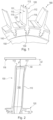
- Figs. 7A - 7D show schematic three-dimensional illustrations of an exemplary embodiment of various pocket forms according to the present patent application.
- the pocket forms are not limited to these examples.
- the pocket 172 has at least partly a semicircular shape. As shown in Fig. 7B the pocket 172 has at least partly a rectangular shape. As shown in Fig. 7C the pocket 172 has at least partly an elliptical shape. As shown in Fig. 7D the pocket 172 has at least partly a circular shape. Preferably, the pocket 172 may have a larger spatial expansion than the outlet 174 of the cooling passage 170.
- Figs. 8A - 8B shows schematic cross-sectional illustrations of an embodiment of a squealer tip cooling system with a cooling channel, wherein a terminal end of the squealer tip is sealed by a sealing element according to the present patent application.
- the cooling passage 170 extends up to the terminal end 74 of the squealer tip 117 to be opened outside in a radially outward direction R, wherein the cooling passage 170 runs at least partly through the pocket 172, and wherein the impingement surface 70 comprises at least partly a sealing element 90 configured to seal the cooling passage 170 at the terminal end 74 of the squealer tip 117.
- the sealing element 90 comprises an inelastic end 92, wherein the inelastic end 92 comprises a single fixing mean 93.
- the sealing element 90 may be a locking element, a closing element, or a plug.
- inelastic means that the corresponding end having the single fixing mean may be bent in an irreversible manner in one direction as indicated by an arrow in Fig. 8A .
- the terminal end 74 of the squealer tip 117 may be at least partly machined (indicated by dotted circles).
- the terminal end 74 may be drilled out such that an insertion of the sealing element 90 may be facilitated.
- a bottom surface 91 of the bent inelastic end 92 of the sealing element 90 may at least partly function as the impingement surface 70.
- the sealing element 90 may be brazed or welded into the terminal end 74 of the squealer tip 117.
- the sealing element 90 may also be a bended wire plug which may be bent into the terminal end 74 of the squealer tip 117.
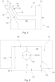
- Figs. 9A - 9B shows schematic cross-sectional illustrations of another embodiment of a squealer tip cooling system with a cooling channel, wherein a terminal end of the squealer tip is sealed by a sealing element according to the present patent application.
- the sealing element 90 comprises an inelastic end 92, wherein the inelastic end 92 comprises two fixing means 93, 94 spaced apart from each other.
- inelastic means that the corresponding end 92 having the two fixing means 93, 94 may be bent in an irreversible manner in two opposed directions as indicated by the two arrows in Fig. 9A .
- Figs. 8A and 8B and Figs. 9A and 9B illustrates sealing element 90 which may close the terminal end 74 of the squealer tip 117 by means of interlocking for positive form locking. Other means of closing may be to braze or weld the sealing element 90 creating an adhesive bond or material closure. In addition, in case of welding the terminal end 74 of the squealer tip 117 may be closed exclusively by welding without using the sealing element 90.
- the terminal end 74 of the squealer tip 117 may be at least partly machined (indicated by dotted circles). For example, the terminal end may be drilled out such that an insertion of the sealing element may be facilitated.
- the bottom surface 91 of the bent inelastic end 92 may at least partly function as the impingement surface 70.
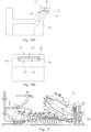
- Fig. 10A shows a schematic cross-sectional illustration of another embodiment of a squealer tip cooling system with a cooling channel, wherein a pocket of the cooling channel is sealed by a sealing element according to the present patent application.
- the sealing element 90 may be a plug insert 95 which may be inserted into the pocket 172.
- the plug insert 95 may be in direct contact with the back surface 176, the lateral surfaces 178 and an upper surface 179 of the pocket 172 such that the cooling medium exclusively exits the pocket 172 via the opening 177.
- the upper surface 179 of the pocket 172 faces the bottom surface 175 of the pocket 172.
- Fig. 10B shows a schematic plan view of the squealer tip cooling system based on Fig. 10A from a direction V indicated by an arrow.
- Fig. 11 show a schematic sectional view of a part of an embodiment of a gas turbine in which an embodiment of the turbine blade assembly comprising the airfoil with the squealer tip cooling system may be incorporated.
- the gas turbine 10 may comprise the turbine blade assembly 180 described herein.
- Fig. 12 shows a schematic flow diagram of an embodiment of a manufacturing method according to the present patent application.
- the manufacturing method M1 of the airfoil 110 with the squealer tip cooling system 50 comprises steps A1, A2 and A3.
- step A1 at least a part of the cooling passage 170 is allocated within the blade tip 113 of the airfoil 110.
- step A2 the remaining part of the cooling passage 170 is provided such that the cooling passage 170 at least partly extends within the squealer tip 117 toward the terminal end 74 of the squealer tip 117.
- step A3 the pocket 172 at the lateral surface 75, 76 of the squealer tip 117 is provided such that the pocket 172 intersects the cooling passage 170, wherein the pocket 172 comprises an impingement surface 70 facing the cooling passage 170, such that a cooling medium expelled through the cooling passage 170 impinges on the impingement surface 70 before being discharged externally through the pocket 172.
- Fig. 13 shows a schematic flow diagram of another embodiment of a manufacturing method according to the present patent application.
- the steps A2 and A3 are conducted by means of additive manufacturing and the manufacturing method further comprises a step A4, wherein the squealer tip 117 manufactured in steps A2 and A3 is aligned on the blade tip 113 manufactured in step A1 to provide the squealer tip cooling system 50.
- the squealer tip cooling system 50 with the blade tip 113 may be manufactured by means of the additive manufacturing, wherein an alignment of the corresponding cooling passages 170 and an adjustment on the blade tip 113 may not be necessary.
- the present invention may further include the following embodiments:
Landscapes
- Engineering & Computer Science (AREA)
- Mechanical Engineering (AREA)
- General Engineering & Computer Science (AREA)
- Chemical & Material Sciences (AREA)
- Combustion & Propulsion (AREA)
- Turbine Rotor Nozzle Sealing (AREA)
Priority Applications (1)
| Application Number | Priority Date | Filing Date | Title |
|---|---|---|---|
| EP23181430.2A EP4234885A3 (de) | 2021-02-04 | 2021-02-04 | Schaufelblatt mit einem system zur kühlung verjüngter schaufelspitzen für eine turbinenlaufschaufel, turbinenlaufschaufel, turbinenlaufschaufelanordnung, gasturbine und verfahren zur herstellung eines schaufelblatts |
Applications Claiming Priority (2)
| Application Number | Priority Date | Filing Date | Title |
|---|---|---|---|
| EP21155254.2A EP4039941B1 (de) | 2021-02-04 | 2021-02-04 | Schaufelblatt mit einem system zur kühlung verjüngter schaufelspitzen für eine turbinenlaufschaufel, turbinenlaufschaufel, turbinenlaufschaufelanordnung, gasturbine und verfahren zur herstellung eines schaufelblatts |
| EP23181430.2A EP4234885A3 (de) | 2021-02-04 | 2021-02-04 | Schaufelblatt mit einem system zur kühlung verjüngter schaufelspitzen für eine turbinenlaufschaufel, turbinenlaufschaufel, turbinenlaufschaufelanordnung, gasturbine und verfahren zur herstellung eines schaufelblatts |
Related Parent Applications (1)
| Application Number | Title | Priority Date | Filing Date |
|---|---|---|---|
| EP21155254.2A Division EP4039941B1 (de) | 2021-02-04 | 2021-02-04 | Schaufelblatt mit einem system zur kühlung verjüngter schaufelspitzen für eine turbinenlaufschaufel, turbinenlaufschaufel, turbinenlaufschaufelanordnung, gasturbine und verfahren zur herstellung eines schaufelblatts |
Publications (2)
| Publication Number | Publication Date |
|---|---|
| EP4234885A2 true EP4234885A2 (de) | 2023-08-30 |
| EP4234885A3 EP4234885A3 (de) | 2023-09-06 |
Family
ID=74553683
Family Applications (2)
| Application Number | Title | Priority Date | Filing Date |
|---|---|---|---|
| EP21155254.2A Active EP4039941B1 (de) | 2021-02-04 | 2021-02-04 | Schaufelblatt mit einem system zur kühlung verjüngter schaufelspitzen für eine turbinenlaufschaufel, turbinenlaufschaufel, turbinenlaufschaufelanordnung, gasturbine und verfahren zur herstellung eines schaufelblatts |
| EP23181430.2A Pending EP4234885A3 (de) | 2021-02-04 | 2021-02-04 | Schaufelblatt mit einem system zur kühlung verjüngter schaufelspitzen für eine turbinenlaufschaufel, turbinenlaufschaufel, turbinenlaufschaufelanordnung, gasturbine und verfahren zur herstellung eines schaufelblatts |
Family Applications Before (1)
| Application Number | Title | Priority Date | Filing Date |
|---|---|---|---|
| EP21155254.2A Active EP4039941B1 (de) | 2021-02-04 | 2021-02-04 | Schaufelblatt mit einem system zur kühlung verjüngter schaufelspitzen für eine turbinenlaufschaufel, turbinenlaufschaufel, turbinenlaufschaufelanordnung, gasturbine und verfahren zur herstellung eines schaufelblatts |
Country Status (4)
| Country | Link |
|---|---|
| US (1) | US11572792B2 (de) |
| EP (2) | EP4039941B1 (de) |
| KR (1) | KR102652378B1 (de) |
| CN (1) | CN114856713B (de) |
Families Citing this family (3)
| Publication number | Priority date | Publication date | Assignee | Title |
|---|---|---|---|---|
| DE102020202891A1 (de) * | 2020-03-06 | 2021-09-09 | Siemens Aktiengesellschaft | Turbinenschaufelspitze, Turbinenschaufel und Verfahren |
| KR102507408B1 (ko) | 2022-11-11 | 2023-03-08 | 터보파워텍(주) | 3d프린팅에 의한 가스터빈 블레이드의 에어포일 수리 공정 |
| KR20250007369A (ko) | 2023-07-05 | 2025-01-14 | 강민조 | 3d프린팅에 의한 가스터빈 블레이드 제작방법 |
Citations (2)
| Publication number | Priority date | Publication date | Assignee | Title |
|---|---|---|---|---|
| EP1764477A1 (de) | 2005-09-14 | 2007-03-21 | General Electric Company | Turbineschaufel mit kannelierter Spitze |
| WO2015069411A1 (en) | 2013-11-11 | 2015-05-14 | United Technologies Corporation | Gas turbine engine turbine blade tip cooling |
Family Cites Families (51)
| Publication number | Priority date | Publication date | Assignee | Title |
|---|---|---|---|---|
| US4487550A (en) * | 1983-01-27 | 1984-12-11 | The United States Of America As Represented By The Secretary Of The Air Force | Cooled turbine blade tip closure |
| US5192192A (en) * | 1990-11-28 | 1993-03-09 | The United States Of America As Represented By The Secretary Of The Air Force | Turbine engine foil cap |
| US5282721A (en) * | 1991-09-30 | 1994-02-01 | United Technologies Corporation | Passive clearance system for turbine blades |
| US6494678B1 (en) * | 2001-05-31 | 2002-12-17 | General Electric Company | Film cooled blade tip |
| US6602052B2 (en) * | 2001-06-20 | 2003-08-05 | Alstom (Switzerland) Ltd | Airfoil tip squealer cooling construction |
| US6971851B2 (en) * | 2003-03-12 | 2005-12-06 | Florida Turbine Technologies, Inc. | Multi-metered film cooled blade tip |
| US6916150B2 (en) * | 2003-11-26 | 2005-07-12 | Siemens Westinghouse Power Corporation | Cooling system for a tip of a turbine blade |
| US7249934B2 (en) * | 2005-08-31 | 2007-07-31 | General Electric Company | Pattern cooled turbine airfoil |
| US7704045B1 (en) * | 2007-05-02 | 2010-04-27 | Florida Turbine Technologies, Inc. | Turbine blade with blade tip cooling notches |
| US7845908B1 (en) * | 2007-11-19 | 2010-12-07 | Florida Turbine Technologies, Inc. | Turbine blade with serpentine flow tip rail cooling |
| US7997865B1 (en) * | 2008-09-18 | 2011-08-16 | Florida Turbine Technologies, Inc. | Turbine blade with tip rail cooling and sealing |
| US8092178B2 (en) * | 2008-11-28 | 2012-01-10 | Pratt & Whitney Canada Corp. | Turbine blade for a gas turbine engine |
| US8157505B2 (en) * | 2009-05-12 | 2012-04-17 | Siemens Energy, Inc. | Turbine blade with single tip rail with a mid-positioned deflector portion |
| US8172507B2 (en) * | 2009-05-12 | 2012-05-08 | Siemens Energy, Inc. | Gas turbine blade with double impingement cooled single suction side tip rail |
| US8066485B1 (en) * | 2009-05-15 | 2011-11-29 | Florida Turbine Technologies, Inc. | Turbine blade with tip section cooling |
| US8414265B2 (en) * | 2009-10-21 | 2013-04-09 | General Electric Company | Turbines and turbine blade winglets |
| US8366394B1 (en) * | 2010-10-21 | 2013-02-05 | Florida Turbine Technologies, Inc. | Turbine blade with tip rail cooling channel |
| US9249670B2 (en) * | 2011-12-15 | 2016-02-02 | General Electric Company | Components with microchannel cooling |
| US20130302166A1 (en) * | 2012-05-09 | 2013-11-14 | Ching-Pang Lee | Turbine blade with chamfered squealer tip formed from multiple components and convective cooling holes |
| US9186757B2 (en) * | 2012-05-09 | 2015-11-17 | Siemens Energy, Inc. | Method of providing a turbine blade tip repair |
| US9297262B2 (en) * | 2012-05-24 | 2016-03-29 | General Electric Company | Cooling structures in the tips of turbine rotor blades |
| US9470096B2 (en) * | 2012-07-26 | 2016-10-18 | General Electric Company | Turbine bucket with notched squealer tip |
| US9273561B2 (en) * | 2012-08-03 | 2016-03-01 | General Electric Company | Cooling structures for turbine rotor blade tips |
| GB201223193D0 (en) * | 2012-12-21 | 2013-02-06 | Rolls Royce Plc | Turbine blade |
| US9856739B2 (en) * | 2013-09-18 | 2018-01-02 | Honeywell International Inc. | Turbine blades with tip portions having converging cooling holes |
| US9879544B2 (en) * | 2013-10-16 | 2018-01-30 | Honeywell International Inc. | Turbine rotor blades with improved tip portion cooling holes |
| DE102013224998A1 (de) * | 2013-12-05 | 2015-06-11 | Rolls-Royce Deutschland Ltd & Co Kg | Turbinenrotorschaufel einer Gasturbine und Verfahren zur Kühlung einer Schaufelspitze einer Turbinenrotorschaufel einer Gasturbine |
| EP3043025A1 (de) * | 2015-01-09 | 2016-07-13 | Siemens Aktiengesellschaft | Filmgekühltes Gasturbinenbauteil |
| US20170370232A1 (en) * | 2015-01-22 | 2017-12-28 | Siemens Energy, Inc. | Turbine airfoil cooling system with chordwise extending squealer tip cooling channel |
| US10001019B2 (en) * | 2015-03-04 | 2018-06-19 | General Electric Company | Turbine rotor blade |
| US20170058680A1 (en) * | 2015-09-02 | 2017-03-02 | General Electric Company | Configurations for turbine rotor blade tips |
| US10436038B2 (en) * | 2015-12-07 | 2019-10-08 | General Electric Company | Turbine engine with an airfoil having a tip shelf outlet |
| US20180051566A1 (en) * | 2016-08-16 | 2018-02-22 | General Electric Company | Airfoil for a turbine engine with a porous tip |
| US10731481B2 (en) * | 2016-11-01 | 2020-08-04 | Rolls-Royce Corporation | Turbine blade with ceramic matrix composite material construction |
| US10400608B2 (en) * | 2016-11-23 | 2019-09-03 | General Electric Company | Cooling structure for a turbine component |
| US10619487B2 (en) * | 2017-01-31 | 2020-04-14 | General Electric Comapny | Cooling assembly for a turbine assembly |
| US10711618B2 (en) * | 2017-05-25 | 2020-07-14 | Raytheon Technologies Corporation | Turbine component with tip film cooling and method of cooling |
| US10830057B2 (en) * | 2017-05-31 | 2020-11-10 | General Electric Company | Airfoil with tip rail cooling |
| US10704406B2 (en) * | 2017-06-13 | 2020-07-07 | General Electric Company | Turbomachine blade cooling structure and related methods |
| US10605098B2 (en) * | 2017-07-13 | 2020-03-31 | General Electric Company | Blade with tip rail cooling |
| US10753207B2 (en) * | 2017-07-13 | 2020-08-25 | General Electric Company | Airfoil with tip rail cooling |
| US10774658B2 (en) * | 2017-07-28 | 2020-09-15 | General Electric Company | Interior cooling configurations in turbine blades and methods of manufacture relating thereto |
| JP7012825B2 (ja) * | 2017-08-14 | 2022-01-28 | シーメンス アクティエンゲゼルシャフト | タービンブレードおよび対応する供与方法 |
| US10738644B2 (en) * | 2017-08-30 | 2020-08-11 | General Electric Company | Turbine blade and method of forming blade tip for eliminating turbine blade tip wear in rubbing |
| US11015453B2 (en) * | 2017-11-22 | 2021-05-25 | General Electric Company | Engine component with non-diffusing section |
| KR102021139B1 (ko) * | 2018-04-04 | 2019-10-18 | 두산중공업 주식회사 | 스퀼러 팁을 구비한 터빈 블레이드 |
| US20190338650A1 (en) * | 2018-05-07 | 2019-11-07 | Rolls-Royce Corporation | Turbine blade squealer tip including internal squealer tip cooling channel |
| KR102153066B1 (ko) * | 2018-10-01 | 2020-09-07 | 두산중공업 주식회사 | 윙렛에 냉각홀을 가진 터빈 블레이드 및 이를 포함하는 가스 터빈 |
| US11208902B2 (en) * | 2018-12-03 | 2021-12-28 | General Electric Company | Tip rail cooling insert for turbine blade tip cooling system and related method |
| US10982553B2 (en) * | 2018-12-03 | 2021-04-20 | General Electric Company | Tip rail with cooling structure using three dimensional unit cells |
| US20240229651A9 (en) * | 2019-10-28 | 2024-07-11 | Siemens Energy Global GmbH & Co. KG | Turbine blade, method of manufacturing a turbine blade and method of refurbishing a turbine blade |
-
2021
- 2021-02-04 EP EP21155254.2A patent/EP4039941B1/de active Active
- 2021-02-04 EP EP23181430.2A patent/EP4234885A3/de active Pending
- 2021-09-29 KR KR1020210129199A patent/KR102652378B1/ko active Active
- 2021-10-21 CN CN202111226077.7A patent/CN114856713B/zh active Active
- 2021-11-23 US US17/534,352 patent/US11572792B2/en active Active
Patent Citations (2)
| Publication number | Priority date | Publication date | Assignee | Title |
|---|---|---|---|---|
| EP1764477A1 (de) | 2005-09-14 | 2007-03-21 | General Electric Company | Turbineschaufel mit kannelierter Spitze |
| WO2015069411A1 (en) | 2013-11-11 | 2015-05-14 | United Technologies Corporation | Gas turbine engine turbine blade tip cooling |
Also Published As
| Publication number | Publication date |
|---|---|
| EP4039941B1 (de) | 2023-06-28 |
| KR20220112656A (ko) | 2022-08-11 |
| US11572792B2 (en) | 2023-02-07 |
| CN114856713A (zh) | 2022-08-05 |
| EP4039941A1 (de) | 2022-08-10 |
| EP4234885A3 (de) | 2023-09-06 |
| CN114856713B (zh) | 2023-11-24 |
| US20220243597A1 (en) | 2022-08-04 |
| KR102652378B1 (ko) | 2024-03-27 |
Similar Documents
| Publication | Publication Date | Title |
|---|---|---|
| EP4039941B1 (de) | Schaufelblatt mit einem system zur kühlung verjüngter schaufelspitzen für eine turbinenlaufschaufel, turbinenlaufschaufel, turbinenlaufschaufelanordnung, gasturbine und verfahren zur herstellung eines schaufelblatts | |
| JP5667348B2 (ja) | ロータブレード及びそれを製作する方法 | |
| EP1462607B1 (de) | Schaufelrad für radialturbine | |
| JP6461382B2 (ja) | シュラウド付きタービンブレード | |
| US10030529B2 (en) | Combined featherseal slot and lightening pocket | |
| CN102953764B (zh) | 连接的叶片平台以及密封方法 | |
| KR20020083498A (ko) | 냉각 팁 슈라우드를 구비하는 터빈 블레이드를 포함하는터빈조립체 | |
| CN104271885A (zh) | 具有由多个部件和对流冷却孔形成的倒角凹槽梢部的涡轮叶片 | |
| KR20070025992A (ko) | 터빈 베인 구성 | |
| CN102733860A (zh) | 涡轮护罩部段冷却系统和方法 | |
| US10323520B2 (en) | Platform cooling arrangement in a turbine rotor blade | |
| US7766619B2 (en) | Convectively cooled gas turbine blade | |
| CN103422992A (zh) | 用于制造热气体路径部件的方法 | |
| EP3645839A1 (de) | Turbinenanordnung zur prallkühlung und verfahren zur montage | |
| EP3192971A1 (de) | Gasturbinenschaufel mit plattformkühlung | |
| CN110159356A (zh) | 制作用于涡轮机零件的冷却组件的方法 | |
| WO2015088699A1 (en) | Gas turbine engine component mateface surfaces | |
| KR102652736B1 (ko) | 가스 터빈 블레이드의 트레일링 엣지 팁 냉각 | |
| RU2688124C2 (ru) | Способ для изготовления узла турбины | |
| EP2700788A1 (de) | Leit- oder Laufsschaufel mit Spitzenabdeckung | |
| US20110255958A1 (en) | Seal member for hot gas path component | |
| KR20160056821A (ko) | 터빈 블레이드 플랫폼-날개부 결합부들을 위한 냉각 |
Legal Events
| Date | Code | Title | Description |
|---|---|---|---|
| PUAI | Public reference made under article 153(3) epc to a published international application that has entered the european phase |
Free format text: ORIGINAL CODE: 0009012 |
|
| STAA | Information on the status of an ep patent application or granted ep patent |
Free format text: STATUS: REQUEST FOR EXAMINATION WAS MADE |
|
| PUAL | Search report despatched |
Free format text: ORIGINAL CODE: 0009013 |
|
| 17P | Request for examination filed |
Effective date: 20230626 |
|
| AC | Divisional application: reference to earlier application |
Ref document number: 4039941 Country of ref document: EP Kind code of ref document: P |
|
| AK | Designated contracting states |
Kind code of ref document: A2 Designated state(s): AL AT BE BG CH CY CZ DE DK EE ES FI FR GB GR HR HU IE IS IT LI LT LU LV MC MK MT NL NO PL PT RO RS SE SI SK SM TR |
|
| AK | Designated contracting states |
Kind code of ref document: A3 Designated state(s): AL AT BE BG CH CY CZ DE DK EE ES FI FR GB GR HR HU IE IS IT LI LT LU LV MC MK MT NL NO PL PT RO RS SE SI SK SM TR |
|
| RIC1 | Information provided on ipc code assigned before grant |
Ipc: F01D 5/20 20060101AFI20230801BHEP |
|
| RBV | Designated contracting states (corrected) |
Designated state(s): AL AT BE BG CH CY CZ DE DK EE ES FI FR GB GR HR HU IE IS IT LI LT LU LV MC MK MT NL NO PL PT RO RS SE SI SK SM TR |