EP4234931A2 - Pompe - Google Patents
Pompe Download PDFInfo
- Publication number
- EP4234931A2 EP4234931A2 EP23174113.3A EP23174113A EP4234931A2 EP 4234931 A2 EP4234931 A2 EP 4234931A2 EP 23174113 A EP23174113 A EP 23174113A EP 4234931 A2 EP4234931 A2 EP 4234931A2
- Authority
- EP
- European Patent Office
- Prior art keywords
- housing part
- pump
- housing
- spring
- ring
- Prior art date
- Legal status (The legal status is an assumption and is not a legal conclusion. Google has not performed a legal analysis and makes no representation as to the accuracy of the status listed.)
- Granted
Links
Images










Classifications
-
- F—MECHANICAL ENGINEERING; LIGHTING; HEATING; WEAPONS; BLASTING
- F01—MACHINES OR ENGINES IN GENERAL; ENGINE PLANTS IN GENERAL; STEAM ENGINES
- F01C—ROTARY-PISTON OR OSCILLATING-PISTON MACHINES OR ENGINES
- F01C19/00—Sealing arrangements in rotary-piston machines or engines
- F01C19/005—Structure and composition of sealing elements such as sealing strips, sealing rings and the like; Coating of these elements
-
- F—MECHANICAL ENGINEERING; LIGHTING; HEATING; WEAPONS; BLASTING
- F04—POSITIVE - DISPLACEMENT MACHINES FOR LIQUIDS; PUMPS FOR LIQUIDS OR ELASTIC FLUIDS
- F04C—ROTARY-PISTON, OR OSCILLATING-PISTON, POSITIVE-DISPLACEMENT MACHINES FOR LIQUIDS; ROTARY-PISTON, OR OSCILLATING-PISTON, POSITIVE-DISPLACEMENT PUMPS
- F04C15/00—Component parts, details or accessories of machines, pumps or pumping installations, not provided for in groups F04C2/00 - F04C14/00
- F04C15/0003—Sealing arrangements in rotary-piston machines or pumps
- F04C15/0007—Radial sealings for working fluid
-
- F—MECHANICAL ENGINEERING; LIGHTING; HEATING; WEAPONS; BLASTING
- F01—MACHINES OR ENGINES IN GENERAL; ENGINE PLANTS IN GENERAL; STEAM ENGINES
- F01C—ROTARY-PISTON OR OSCILLATING-PISTON MACHINES OR ENGINES
- F01C21/00—Component parts, details or accessories not provided for in groups F01C1/00 - F01C20/00
- F01C21/10—Outer members for co-operation with rotary pistons; Casings
- F01C21/104—Stators; Members defining the outer boundaries of the working chamber
- F01C21/108—Stators; Members defining the outer boundaries of the working chamber with an axial surface, e.g. side plates
-
- F—MECHANICAL ENGINEERING; LIGHTING; HEATING; WEAPONS; BLASTING
- F01—MACHINES OR ENGINES IN GENERAL; ENGINE PLANTS IN GENERAL; STEAM ENGINES
- F01M—LUBRICATING OF MACHINES OR ENGINES IN GENERAL; LUBRICATING INTERNAL COMBUSTION ENGINES; CRANKCASE VENTILATING
- F01M1/00—Pressure lubrication
- F01M1/02—Pressure lubrication using lubricating pumps
-
- F—MECHANICAL ENGINEERING; LIGHTING; HEATING; WEAPONS; BLASTING
- F04—POSITIVE - DISPLACEMENT MACHINES FOR LIQUIDS; PUMPS FOR LIQUIDS OR ELASTIC FLUIDS
- F04C—ROTARY-PISTON, OR OSCILLATING-PISTON, POSITIVE-DISPLACEMENT MACHINES FOR LIQUIDS; ROTARY-PISTON, OR OSCILLATING-PISTON, POSITIVE-DISPLACEMENT PUMPS
- F04C14/00—Control of, monitoring of, or safety arrangements for, machines, pumps or pumping installations
- F04C14/02—Control of, monitoring of, or safety arrangements for, machines, pumps or pumping installations specially adapted for several machines or pumps connected in series or in parallel
-
- F—MECHANICAL ENGINEERING; LIGHTING; HEATING; WEAPONS; BLASTING
- F04—POSITIVE - DISPLACEMENT MACHINES FOR LIQUIDS; PUMPS FOR LIQUIDS OR ELASTIC FLUIDS
- F04C—ROTARY-PISTON, OR OSCILLATING-PISTON, POSITIVE-DISPLACEMENT MACHINES FOR LIQUIDS; ROTARY-PISTON, OR OSCILLATING-PISTON, POSITIVE-DISPLACEMENT PUMPS
- F04C15/00—Component parts, details or accessories of machines, pumps or pumping installations, not provided for in groups F04C2/00 - F04C14/00
- F04C15/0003—Sealing arrangements in rotary-piston machines or pumps
- F04C15/0023—Axial sealings for working fluid
-
- F—MECHANICAL ENGINEERING; LIGHTING; HEATING; WEAPONS; BLASTING
- F04—POSITIVE - DISPLACEMENT MACHINES FOR LIQUIDS; PUMPS FOR LIQUIDS OR ELASTIC FLUIDS
- F04C—ROTARY-PISTON, OR OSCILLATING-PISTON, POSITIVE-DISPLACEMENT MACHINES FOR LIQUIDS; ROTARY-PISTON, OR OSCILLATING-PISTON, POSITIVE-DISPLACEMENT PUMPS
- F04C15/00—Component parts, details or accessories of machines, pumps or pumping installations, not provided for in groups F04C2/00 - F04C14/00
- F04C15/0003—Sealing arrangements in rotary-piston machines or pumps
- F04C15/0034—Sealing arrangements in rotary-piston machines or pumps for other than the working fluid, i.e. the sealing arrangements are not between working chambers of the machine
-
- F—MECHANICAL ENGINEERING; LIGHTING; HEATING; WEAPONS; BLASTING
- F04—POSITIVE - DISPLACEMENT MACHINES FOR LIQUIDS; PUMPS FOR LIQUIDS OR ELASTIC FLUIDS
- F04C—ROTARY-PISTON, OR OSCILLATING-PISTON, POSITIVE-DISPLACEMENT MACHINES FOR LIQUIDS; ROTARY-PISTON, OR OSCILLATING-PISTON, POSITIVE-DISPLACEMENT PUMPS
- F04C15/00—Component parts, details or accessories of machines, pumps or pumping installations, not provided for in groups F04C2/00 - F04C14/00
- F04C15/06—Arrangements for admission or discharge of the working fluid, e.g. constructional features of the inlet or outlet
-
- F—MECHANICAL ENGINEERING; LIGHTING; HEATING; WEAPONS; BLASTING
- F04—POSITIVE - DISPLACEMENT MACHINES FOR LIQUIDS; PUMPS FOR LIQUIDS OR ELASTIC FLUIDS
- F04C—ROTARY-PISTON, OR OSCILLATING-PISTON, POSITIVE-DISPLACEMENT MACHINES FOR LIQUIDS; ROTARY-PISTON, OR OSCILLATING-PISTON, POSITIVE-DISPLACEMENT PUMPS
- F04C2/00—Rotary-piston machines or pumps
- F04C2/30—Rotary-piston machines or pumps having the characteristics covered by two or more groups F04C2/02, F04C2/08, F04C2/22, F04C2/24 or having the characteristics covered by one of these groups together with some other type of movement between co-operating members
- F04C2/34—Rotary-piston machines or pumps having the characteristics covered by two or more groups F04C2/02, F04C2/08, F04C2/22, F04C2/24 or having the characteristics covered by one of these groups together with some other type of movement between co-operating members having the movement defined in groups F04C2/08 or F04C2/22 and relative reciprocation between the co-operating members
- F04C2/344—Rotary-piston machines or pumps having the characteristics covered by two or more groups F04C2/02, F04C2/08, F04C2/22, F04C2/24 or having the characteristics covered by one of these groups together with some other type of movement between co-operating members having the movement defined in groups F04C2/08 or F04C2/22 and relative reciprocation between the co-operating members with vanes reciprocating with respect to the inner member
- F04C2/3441—Rotary-piston machines or pumps having the characteristics covered by two or more groups F04C2/02, F04C2/08, F04C2/22, F04C2/24 or having the characteristics covered by one of these groups together with some other type of movement between co-operating members having the movement defined in groups F04C2/08 or F04C2/22 and relative reciprocation between the co-operating members with vanes reciprocating with respect to the inner member the inner and outer member being in contact along one line or continuous surface substantially parallel to the axis of rotation
- F04C2/3445—Rotary-piston machines or pumps having the characteristics covered by two or more groups F04C2/02, F04C2/08, F04C2/22, F04C2/24 or having the characteristics covered by one of these groups together with some other type of movement between co-operating members having the movement defined in groups F04C2/08 or F04C2/22 and relative reciprocation between the co-operating members with vanes reciprocating with respect to the inner member the inner and outer member being in contact along one line or continuous surface substantially parallel to the axis of rotation the vanes having the form of rollers, slippers or the like
-
- F—MECHANICAL ENGINEERING; LIGHTING; HEATING; WEAPONS; BLASTING
- F04—POSITIVE - DISPLACEMENT MACHINES FOR LIQUIDS; PUMPS FOR LIQUIDS OR ELASTIC FLUIDS
- F04C—ROTARY-PISTON, OR OSCILLATING-PISTON, POSITIVE-DISPLACEMENT MACHINES FOR LIQUIDS; ROTARY-PISTON, OR OSCILLATING-PISTON, POSITIVE-DISPLACEMENT PUMPS
- F04C2/00—Rotary-piston machines or pumps
- F04C2/30—Rotary-piston machines or pumps having the characteristics covered by two or more groups F04C2/02, F04C2/08, F04C2/22, F04C2/24 or having the characteristics covered by one of these groups together with some other type of movement between co-operating members
- F04C2/34—Rotary-piston machines or pumps having the characteristics covered by two or more groups F04C2/02, F04C2/08, F04C2/22, F04C2/24 or having the characteristics covered by one of these groups together with some other type of movement between co-operating members having the movement defined in groups F04C2/08 or F04C2/22 and relative reciprocation between the co-operating members
- F04C2/344—Rotary-piston machines or pumps having the characteristics covered by two or more groups F04C2/02, F04C2/08, F04C2/22, F04C2/24 or having the characteristics covered by one of these groups together with some other type of movement between co-operating members having the movement defined in groups F04C2/08 or F04C2/22 and relative reciprocation between the co-operating members with vanes reciprocating with respect to the inner member
- F04C2/3446—Rotary-piston machines or pumps having the characteristics covered by two or more groups F04C2/02, F04C2/08, F04C2/22, F04C2/24 or having the characteristics covered by one of these groups together with some other type of movement between co-operating members having the movement defined in groups F04C2/08 or F04C2/22 and relative reciprocation between the co-operating members with vanes reciprocating with respect to the inner member the inner and outer member being in contact along more than one line or surface
-
- F—MECHANICAL ENGINEERING; LIGHTING; HEATING; WEAPONS; BLASTING
- F04—POSITIVE - DISPLACEMENT MACHINES FOR LIQUIDS; PUMPS FOR LIQUIDS OR ELASTIC FLUIDS
- F04C—ROTARY-PISTON, OR OSCILLATING-PISTON, POSITIVE-DISPLACEMENT MACHINES FOR LIQUIDS; ROTARY-PISTON, OR OSCILLATING-PISTON, POSITIVE-DISPLACEMENT PUMPS
- F04C2/00—Rotary-piston machines or pumps
- F04C2/30—Rotary-piston machines or pumps having the characteristics covered by two or more groups F04C2/02, F04C2/08, F04C2/22, F04C2/24 or having the characteristics covered by one of these groups together with some other type of movement between co-operating members
- F04C2/34—Rotary-piston machines or pumps having the characteristics covered by two or more groups F04C2/02, F04C2/08, F04C2/22, F04C2/24 or having the characteristics covered by one of these groups together with some other type of movement between co-operating members having the movement defined in groups F04C2/08 or F04C2/22 and relative reciprocation between the co-operating members
- F04C2/344—Rotary-piston machines or pumps having the characteristics covered by two or more groups F04C2/02, F04C2/08, F04C2/22, F04C2/24 or having the characteristics covered by one of these groups together with some other type of movement between co-operating members having the movement defined in groups F04C2/08 or F04C2/22 and relative reciprocation between the co-operating members with vanes reciprocating with respect to the inner member
- F04C2/3448—Rotary-piston machines or pumps having the characteristics covered by two or more groups F04C2/02, F04C2/08, F04C2/22, F04C2/24 or having the characteristics covered by one of these groups together with some other type of movement between co-operating members having the movement defined in groups F04C2/08 or F04C2/22 and relative reciprocation between the co-operating members with vanes reciprocating with respect to the inner member with axially movable vanes
-
- F—MECHANICAL ENGINEERING; LIGHTING; HEATING; WEAPONS; BLASTING
- F01—MACHINES OR ENGINES IN GENERAL; ENGINE PLANTS IN GENERAL; STEAM ENGINES
- F01M—LUBRICATING OF MACHINES OR ENGINES IN GENERAL; LUBRICATING INTERNAL COMBUSTION ENGINES; CRANKCASE VENTILATING
- F01M1/00—Pressure lubrication
- F01M1/02—Pressure lubrication using lubricating pumps
- F01M2001/0207—Pressure lubrication using lubricating pumps characterised by the type of pump
- F01M2001/023—Piston pumps
-
- F—MECHANICAL ENGINEERING; LIGHTING; HEATING; WEAPONS; BLASTING
- F01—MACHINES OR ENGINES IN GENERAL; ENGINE PLANTS IN GENERAL; STEAM ENGINES
- F01M—LUBRICATING OF MACHINES OR ENGINES IN GENERAL; LUBRICATING INTERNAL COMBUSTION ENGINES; CRANKCASE VENTILATING
- F01M1/00—Pressure lubrication
- F01M1/02—Pressure lubrication using lubricating pumps
- F01M2001/0207—Pressure lubrication using lubricating pumps characterised by the type of pump
- F01M2001/0238—Rotary pumps
-
- F—MECHANICAL ENGINEERING; LIGHTING; HEATING; WEAPONS; BLASTING
- F01—MACHINES OR ENGINES IN GENERAL; ENGINE PLANTS IN GENERAL; STEAM ENGINES
- F01M—LUBRICATING OF MACHINES OR ENGINES IN GENERAL; LUBRICATING INTERNAL COMBUSTION ENGINES; CRANKCASE VENTILATING
- F01M1/00—Pressure lubrication
- F01M1/02—Pressure lubrication using lubricating pumps
- F01M2001/0292—Sealings
-
- F—MECHANICAL ENGINEERING; LIGHTING; HEATING; WEAPONS; BLASTING
- F04—POSITIVE - DISPLACEMENT MACHINES FOR LIQUIDS; PUMPS FOR LIQUIDS OR ELASTIC FLUIDS
- F04C—ROTARY-PISTON, OR OSCILLATING-PISTON, POSITIVE-DISPLACEMENT MACHINES FOR LIQUIDS; ROTARY-PISTON, OR OSCILLATING-PISTON, POSITIVE-DISPLACEMENT PUMPS
- F04C2/00—Rotary-piston machines or pumps
- F04C2/08—Rotary-piston machines or pumps of intermeshing-engagement type, i.e. with engagement of co-operating members similar to that of toothed gearing
-
- F—MECHANICAL ENGINEERING; LIGHTING; HEATING; WEAPONS; BLASTING
- F04—POSITIVE - DISPLACEMENT MACHINES FOR LIQUIDS; PUMPS FOR LIQUIDS OR ELASTIC FLUIDS
- F04C—ROTARY-PISTON, OR OSCILLATING-PISTON, POSITIVE-DISPLACEMENT MACHINES FOR LIQUIDS; ROTARY-PISTON, OR OSCILLATING-PISTON, POSITIVE-DISPLACEMENT PUMPS
- F04C2/00—Rotary-piston machines or pumps
- F04C2/30—Rotary-piston machines or pumps having the characteristics covered by two or more groups F04C2/02, F04C2/08, F04C2/22, F04C2/24 or having the characteristics covered by one of these groups together with some other type of movement between co-operating members
- F04C2/34—Rotary-piston machines or pumps having the characteristics covered by two or more groups F04C2/02, F04C2/08, F04C2/22, F04C2/24 or having the characteristics covered by one of these groups together with some other type of movement between co-operating members having the movement defined in groups F04C2/08 or F04C2/22 and relative reciprocation between the co-operating members
- F04C2/344—Rotary-piston machines or pumps having the characteristics covered by two or more groups F04C2/02, F04C2/08, F04C2/22, F04C2/24 or having the characteristics covered by one of these groups together with some other type of movement between co-operating members having the movement defined in groups F04C2/08 or F04C2/22 and relative reciprocation between the co-operating members with vanes reciprocating with respect to the inner member
-
- F—MECHANICAL ENGINEERING; LIGHTING; HEATING; WEAPONS; BLASTING
- F04—POSITIVE - DISPLACEMENT MACHINES FOR LIQUIDS; PUMPS FOR LIQUIDS OR ELASTIC FLUIDS
- F04C—ROTARY-PISTON, OR OSCILLATING-PISTON, POSITIVE-DISPLACEMENT MACHINES FOR LIQUIDS; ROTARY-PISTON, OR OSCILLATING-PISTON, POSITIVE-DISPLACEMENT PUMPS
- F04C2240/00—Components
- F04C2240/30—Casings or housings
Definitions
- the pump insert can have a first inlet channel for the first delivery chamber and a second inlet channel separate therefrom for the second delivery chamber and a first outlet channel for the first delivery chamber and a second outlet channel separate therefrom for the second delivery chamber or a common outlet channel for the first and second Have pumping chamber.
- first pumping chamber fluid z. B.
- other or the same consumers are supplied as with the funded via the second pumping chamber fluid.
- different pressure levels can arise between the first outlet channel and the second outlet channel or between the first pressure chamber into which the first outlet channel opens and the second pressure chamber into which the second outlet channel opens.
- the conveying elements and/or the rotor each form a pressure gap with the first housing part and the second housing part.
- the easy handling of the pump insert this can in the receiving housing z. B. can be formed by a transmission housing for a motor vehicle, are included or used in the receiving housing, z. B. via one of the end wall opposite opening of the receiving housing.
- the spring can be supported directly or indirectly on the second housing part.
- an intermediate part can be arranged between the second housing part and the spring, with the spring being supported on the intermediate part.
- the intermediate part can be supported on the second housing part, preferably likewise in a region which is arranged in axial alignment with the cam ring in the direction of the axis of rotation.
- the intermediate part can, for. B. a so-called cold start plate or a plate-shaped structure such. B. a perforated (metal) sheet or a screen structure, have or be.
- the intermediate part can, for. B. bordered or arranged between the spring and the second housing part and / or held or attached to the at least one positioning element be, such as B. each positioning element to which it is attached, have a recess or bore through which the positioning element in question extends.
- the intermediate part can have at least one area with the sieve-like structure or at least one perforated area, e.g. B. a single, two or more such areas.
- the intermediate part and/or the spring, on which the intermediate part can be resiliently supported can be designed so flexibly that the intermediate part lifts off the second housing part at least partially when a limit pressure is reached, as a result Liquid can flow from the pumping chamber through a gap formed thereby between the intermediate part and the second housing part.
- a multi-corrugated spring washer can have or consist of a spring structure made of metal, in particular steel, the spring structure being formed from a flat or round material, which forms a closed ring in particular. At least in the unloaded state, the spring is wavy over the circumferential direction of the ring, ie designed wavy or with several waves, in particular with several wave crests and wave troughs. The wave height extends along or towards the axis of rotation or substantially perpendicular or normal to the plane passing through the annular Spring structure is stretched.
- the multi-corrugated spring has the advantage that it can be used in a very space-saving manner.
- the spring structure can have an initial coil and/or an end coil, with the initial coil and/or the end coil extending substantially planarly around the longitudinal axis of the spring.
- the spring With the initial turn and/or the end turn, the spring can be supported on the end wall and/or directly or indirectly on the second housing part. Through the initial coil and the final coil, a better fit, i.e. H. causes the spring force to be distributed over a larger area on the parts on which the spring is supported.
- the longitudinal axis of the spring is parallel or lies on the axis of rotation.
- the initial turn may include the fastener for attachment to the positioning member.
- a (metal) C-ring or a (metal) O-ring is ring-shaped.
- the spring structure extends at least in sections over the circumference of the longitudinal axis of the spring.
- the longitudinal axis of the spring is vertical or is normal to the surface spanned by the ring.
- the longitudinal axis of the spring is essentially parallel to or lies on the axis of rotation of the rotor.
- the ring may be flat or substantially uncorrugated about its circumference.
- the spring structure is C-shaped in cross-section which is transverse to the circumferential direction, ie with an open contour, and in the case of the (metal) O-ring it is O-shaped, ie with a closed contour.
- a fastening element for fastening to the positioning element can be formed in each case between adjacent sections which have a C- or O-ring-shaped spring structure.
- the springs referred to herein may have multiple fasteners for multiple positioning members.
- annular sealing element (seal or axial seal) is arranged between the end wall and the second housing part, in particular the sealing element described in general and/or for the first aspect, which forms a pressure chamber between the end wall and the second housing part, in particular the second pressure chamber, wherein the pressure chamber is connected via an outlet channel to a pumping chamber formed between the rotor and the cam ring.
- the spring has a spring structure made of metal, in particular spring steel, which gives the spring its essential spring property, the annular sealing element being fastened to the spring structure, in particular being fastened captively.
- the spring and the sealing element can form a unit or an integral unit that can be handled as a unit.
- the spring structure can, for. B. have an additional annular portion which is part of the sealing element and with a sealing material such. B. a polymer or elastomer is molded or coated.
- the additional ring-shaped section acts as a support structure, which counteracts an extrusion out or a gap extrusion of the sealing material of the sealing element due to the pressure difference between the first pressure chamber and the second pressure chamber.
- the spring structure can have a further annular section, which is also overmoulded or coated with the sealing material.
- This further additional annular section can annularly surround the axis of rotation of the rotor, in particular the pump shaft if it extends through the second housing part, in order to seal off the first pressure chamber and/or the second pressure chamber with respect to the pump shaft.
- the seal or the sealing element, which surrounds the second pressure chamber is preferably arranged eccentrically to the axis of rotation of the rotor, in particular in an area between the annular spring, which at least partially surrounds the first pressure chamber, and the pump shaft or an area that extends in the direction of the Axis of rotation is arranged in an axial alignment with the pump shaft.
- a first pressure chamber and a second pressure chamber are formed between the end wall and the second housing part, as has already been described above.
- An annular sealing element as already described, is arranged between the end wall and the second housing part, which encloses the second pressure chamber and seals it off with respect to the first pressure chamber.
- the first pressure chamber is connected via a first outlet channel to a first pumping chamber formed between the rotor and the cam ring
- the second pressure chamber is connected via a second outlet channel to a second pumping chamber formed between the rotor and the cam ring.
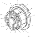
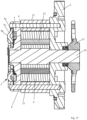
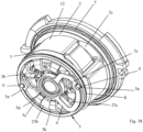
- the figures 2 , 3 , 17 and 18 show pump inserts that can be inserted into a receiving housing, as in figure 1 shown.
- the pump in particular the pump insert 1, comprises a spring 5, which is shown here in various embodiments.
- the pump or the pump insert 1 can have a seal 9 , in particular an axial seal, arranged between an end wall 20c of a receiving housing 20 and a second housing part 3 .
- the seal 9 is shown partially combined with the spring 5 in various embodiments.
- the pump or the pump insert 1 has a rotor 4 which is connected in a torque-proof manner to a pump shaft 10 via a shaft-hub connection 30 .
- the rotor 4 has recesses, in particular slot-shaped recesses, which serve as guides.
- a conveying element 13, in particular a vane, is assigned to each recess.
- the vane 13 is at its recess radially or away from the axis of rotation D of the rotor 4 and to the axis of rotation D of the Rotor 4 can be moved out, in particular with a single translational degree of freedom, moved back and forth, such. e.g figure 20 is recognizable.
- the wings 13 are rotated with the rotor 4.
- the pump 1 has an annular housing part, namely a cam ring 12 .
- the cam ring 12 is sandwiched between a first housing part 2 and a second housing part 3 and is non-rotatable with respect to the first and second housing parts 2, 3.
- the second and third housing part 2, 3 is limited, can also be referred to as the pump chamber 26.
- the rotor 4 and the vanes 13 are arranged in the pump chamber 26 .
- a delivery cell 29 is formed between adjacent vanes 13, the volume of which changes depending on the rotational position of the rotor 4 about its axis of rotation D. Since the pump has a plurality of vanes 13, it also has a corresponding number of delivery cells 29. Several delivery cells 29 are located in each of the delivery chambers 27, 28.
- the cam ring 12 and/or the vanes 13 can be magnetized, so that the vanes 13 bear against the inner peripheral surface of the cam ring 12 due to magnetic force, in particular even when the rotor 4 is not rotating. This allows pressure to build up early when starting or cold starting, i. H. when the pump shaft 10 starts rotating.
- the vanes 13 can rotate outwards, i. H. are pressed away from the axis of rotation of the rotor 4 against the inner peripheral surface of the cam ring 12.
- the wings 13 or each of the wings 13 forms a third sealing gap with the inner peripheral surface of the cam ring 12 .
- the inner peripheral surface of the cam ring 12 has a contour which causes the vanes 13 to extend at least once for a full revolution of the rotor 4 (Increase in volume of the delivery cell 29) and retract once (decrease in volume of the delivery cell 29).
- the pump shown in the example is double-stroke, ie with two delivery chambers 27, 28, the vanes 13 extending once per delivery chamber 27, 28 and retracting once when they are moved through the delivery chamber 27, 28 by rotation of the rotor 4.
- the blades 13 are caused to extend, retract, extend and retract again for one full revolution of the rotor 4, or in other words extend twice and retract twice.
- a delivery cell 29 is formed between adjacent wings 13, the volume of which increases or decreases as a result of the extension and retraction of the wings 13 delimiting this delivery cell 29, namely depending on the contour of the inner peripheral surface of the cam ring 12.
- the pump insert 1 comprises at least one positioning element 6, in the example shown two positioned elements 6.
- the positioning elements 6 are pins or pin-shaped.
- the positioning element 6 is firmly anchored in the first housing part 2 .
- the first housing part 2 has a blind hole 2a, into which the pin-shaped positioning element 6 is pressed with a first end.
- the pin-shaped positioning element 6 positions the second housing part 3 and the cam ring 12 with respect to their angular positions about the axis of rotation D relative to the first housing part 2.
- the second housing part 3 and the cam ring 12 have recesses, openings, bores or elongated holes, preferably with a radial extension. through which the positioning element 6 extends.
- the cam ring 12 has a bore 12a for the first positioning element 6 and a further bore 12a for the second positioning element 6 for this purpose.
- the second housing part 3 has a through hole through which the positioning element 6 extends.
- the pin-shaped second end of the positioning element 6 protrudes beyond the end face that points away from the pump chamber 26 .
- This protruding portion of the positioning element 6 has a recess, such as. B. an annular groove 6a, or at least a part thereof, which extends over the circumference of the positioning element 6.
- a securing element or fastening element 5a of the spring 5 is arranged in the recess 6a and is fastened in particular in a non-positive and/or positive manner to the positioning element 6 or in the annular groove 6a.
- the fastening element 5a prevents the first housing part 2, the second housing part 3 and the cam ring 12 from falling apart axially, or in other words, the second housing part 3 and the cam ring 12 from being pulled off the positioning element 6. This also makes the spring 5 captive on the pump insert 1, in particular the positioning elements 6 attached.
- the pump shaft 10 is rotatably mounted on the first and second housing part 2, 3, in particular by means of a slide bearing in each case.
- this can be done without the support in the second housing part 3 or only with the Storage in the first housing part 2 is sufficient, in particular when the pump insert 1 is double-stroke, ie has two pumping chambers 27, 28 which are opposite one another, for example in relation to the axis of rotation D.
- the forces caused by the pressures in the pumping chambers 27, 28 transverse to the axis of rotation D can cancel each other out as a result.
- an external structure such as. B. formed an external toothing on the pump shaft 10, which is in a form-fitting engagement with a corresponding internal structure, in particular internal toothing of the rotor 4, to form a shaft-hub connection 30.
- the outer diameter of the outer structure of the pump shaft 10 is larger than the diameter of the section of the pump shaft 10 that is mounted in the first housing part 2 and/or in the second housing part 3 .
- the pump shaft 10 is axially fixed between the first and second housing parts 2, 3, i.
- the outer diameter of the sections of the first housing part 2 and the second housing part 3, which support the pump shaft 10 is smaller than the outer diameter of the outer structure of the pump shaft 10.
- the first housing part 2 has, on its front side facing away from the pump chamber 26 , an annular pocket in which a shaft seal 11 is arranged, which is fastened to the first housing part 2 in a rotationally fixed manner and forms a sealing gap with the pump shaft 10 .
- the shaft seal 11 seals off the pump chamber 26 from the outside.
- the end of the pump shaft 10 which is opposite the end which is arranged in the area of the spring 5 has an outer contour for a shaft-hub connection 30 with a drive wheel, in particular gear wheel 21, in particular a chain wheel.
- the gear 21 is non-rotatably seated on the pump shaft 10.
- the gear 21 can be driven by a chain, which in turn can be driven by z. B. a crankshaft or other shaft connected to z. B. may be connected to an engine of the vehicle is driven.
- the gear 21 has for its attachment to the pump shaft 10 z. B. has an internal thread with which it is screwed to an external thread of the pump shaft 10 against a shoulder of the pump shaft 10 .
- An anti-rotation lock seated on the shaft 10 secures the gear wheel 21 against unintentional loosening.
- the drive wheel 21 by means of a Joined or attached to the pump shaft 10 by interference fit or other types of connection.
- the pump insert 1 is in the examples shown in a z. B. cup-shaped receiving housing 20, such as. B. used a housing pot ( figure 1 ).
- the receiving housing 20 has a peripheral wall 20d which surrounds one of the pump inserts 1 shown here on the peripheral side. Furthermore, the receiving housing 20 has an end wall 20c which is monolithically connected to the peripheral wall 20d, the spring 5 being supported on the end wall 20c in particular axially, ie in the direction of the axis of rotation D.
- the pump insert 1 is between the end wall 20c and an axial securing element, such as. B. a screw, an axial locking ring or a cover so that the spring 5 is tensioned or remains, in particular is tensioned or remains under pressure.
- the axial securing element can bear against the first housing part 2 and/or can hold the first housing part 2 in a non-displaceable manner on the receiving housing 20 along or in the direction of the axis of rotation D.
- the seal 9 is arranged in a sealing groove or a sealing pocket of the second housing part 3 which annularly surrounds one end of the second outlet channel 3c, the bottom of the groove or the bottom of the pocket forming a sealing surface for the seal 9 .
- the wall the groove or pocket which annularly surrounds the seal is at a distance from the end wall 20c which is less than the height of the seal 9, in particular than the height of the first ring 9a, which will be described further below.
- a gap extrusion of the seal 9 is prevented by the first ring 9a, in particular its material, and/or the smaller gap width between wall and end wall 20c.
- a gap extrusion can also be avoided by a support structure in the seal 9 .
- the first and second housing parts 2, 3 and the cam ring 12 are sealed off from one another.
- the connection between the axial securing element and the first housing part 2 is made so strong that it can withstand the axial force on the axial securing element, as caused by the pressure in the pressure chambers 23b, 23c, i. H. is not resolved.
- the axial securing element is a housing cover which is fastened to the receiving housing 20 and on which the first housing part 2 is supported axially.
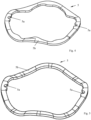
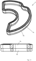
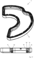
- a spring 5 z. B a suitably designed corrugated ring spring, a multi-corrugated spring washer, a hose or arc spring, a grooved ring spring, a metal O-ring or a metal C-ring in question. If the spring 5 is to be fastened to the positioning elements 6, the spring can have fastening elements 5a for fastening them to the positioning elements 6.
- the spring 5 On its circumference, the spring 5 has several, here two, fastening elements 5a in the form of recesses which are open towards the inner circumference and which can be arranged in the annular groove 6a of a positioning element 6 .
- the thickness of the flat material of the spring 5 is less than the groove width of the annular groove 6a.
- the spring 5 off figure 5 is so far identical to the spring 5 from figure 4 .
- the spring 5 off figure 4 additionally has several inwardly protruding protrusions on its inner circumference.
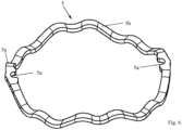
- the spring 5 off figure 6 essentially corresponds to the design figure 5 , wherein the spring structure 5b from figure 6 more waves than the embodiment figure 5 has, ie is more corrugated.
- the spring structure 5b has a positioning element 5e, which can engage in a corresponding recess in the second housing part 3 in order to fasten the spring 5 to the fastening elements 6 in the correct position.
- FIG 7 shows an annular spring 5, which has several tubular sections 5f over its circumference, in this example two tubular sections 5f. Between adjacent tubular portions 5f there is arranged a fastener 5a and in particular a flat portion 5g in which the fastener 5a is formed.
- the fastening element 5a is a recess open towards the inner circumference of the ring.
- the thickness of the flat portion 5g is smaller than the groove width of the annular groove 6a of the positioning member 6.
- the flat portion 5g can be formed by compressing and plastically deforming a previously continuous tubular portion 5f. In the example shown there are two fasteners 5a and thus two flat portions 5g.
- the spring 5 has two tubular sections 5f, which are connected at their ends respectively via a flat section 5g, which is provided with a fastening element 5a.
- the embodiment off figure 8 shows a spring 5 identical to the spring from figure 7 is, with the exception of the configuration of the tubular portions 5f.
- the execution off figure 8 namely has C-shaped sections 5h instead of a tubular section 5f. Otherwise, execution will depend on it figure 7 referred.
- the C-shaped sections 5h each have a contour that is open in cross section, namely a slot that extends over the circumference, in particular the inner circumference of the ring-shaped spring structure.
- the springs 5 or spring structures 5b from the Figures 4 to 8 are preferably made of metal, in particular spring steel.
- the springs 5 can be coated or encapsulated, in particular with a plastic, such as. B. a polymer or elastomeric or thermoplastic material or z. B. with a paint.
- Polytetrafluoroethylene is particularly suitable, the core strength of which can be increased by inserted fibers, for example glass fibers, so that the axial seal can withstand considerable pressure.
- ethylene-tetrafluoroethylene copolymer ETFE
- Polyterephthalate is also well suited for the intended purpose, since it can be easily vulcanized with the sealing ring.
- Polyamides, with or without a glass fiber insert, are also suitable for the intended purpose.
- the second ring 9b is preferably made of a plastic, in particular an elastomeric or rubber-elastic material or elastomer, which is preferably readily vulcanizable, does not tear and is not highly sensitive to notches.
- a plastic in particular an elastomeric or rubber-elastic material or elastomer, which is preferably readily vulcanizable, does not tear and is not highly sensitive to notches.
- the listed materials and materials also apply in particular, but not only to the statements from the figures 10 , 11 , 15 and 16 , but can be used, for example, for all embodiments shown or described in the present application.
- the first ring 9a has a V-shaped groove over its circumference.
- a counterpart formed by the second ring and adapted to this shape of the groove is arranged in the groove and is connected, in particular vulcanized or glued, to the first ring 9a in the groove.
- figure 15 shows a first ring 9a, which has a step running around its annular circumference, in which the second ring 9b, which is designed as an O-ring, is accommodated.
- the second ring 9b is integrally connected to the first ring 9a.
- the second ring 9b is loosely inserted into the first ring 9a, in particular into the stepped shoulder.
- the front end of the seal which is opposite the front end formed by the second ring 9b, has at least one groove running around the annular circumference of the first ring 9a.
- the groove is bordered by a first circumferential, in particular inner groove wall 9c and a second circumferential, in particular outer groove wall 9d.
- the first groove wall 9c is continuous over the circumference and is supported on its sealing surface in a sealing manner, as a result of which the first pressure chamber 23b is sealed off from the second pressure chamber 23c.
- the second groove wall 9d is provided with a plurality of recesses over its circumference, which make the second groove wall 9d liquid-permeable, as a result of which only the first groove wall 9c is sealed.
- the second groove wall 9d serves to support the seal on the sealing surface so that the seal 9 does not tilt.
- the second groove wall 9d can be continuous over the circumference and the first groove wall 9c can be provided with the plurality of recesses, with the above-described being transferable to this embodiment.
- the second groove wall 9d can primarily serve for sealing and the first groove wall 9c primarily for support.
- FIG 16 shows a seal 9, which consists of only one ring, such as. B. from the material for the above first ring 9a or the above second ring 9b, depending according to the expected pressure difference between the first pressure chamber 23b and the second pressure chamber 23c.
- a front end of the seal is designed with a sealing lip, which has an inclined inner surface, which is inclined in such a way that internal pressure in the second pressure chamber 23c exerts a force on the sealing lip, which at least partially acts against the sealing surface of the second housing part 3 or the end wall 20c presses.
- On the inner circumference is a variety of z. B. arranged along the height of the seal 5 or in the direction of the axis of rotation D extended recesses z. B.
- sealing lip is open towards the inner circumference to ensure that the sealing lip, even if it is deformed in the assembled state of the pump insert 1 in the receiving housing 20, is subjected to pressure fluid from the second pressure chamber 23c in order to press it against its sealing surface, e.g second housing part 3 is formed to press.
- the face of the seal 9 opposite the sealing lip can be flat or even or as shown in figure 15 be designed.
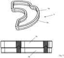
- figure 12 shows an annular seal 9, which has a first ring 9a made of the above-mentioned first material, alternatively made of metal, in particular steel, which is essentially completely coated or encapsulated over its surface with plastic, in particular the elastomeric or rubber-elastic or thermoplastic material, whereby a second ring 9b is formed.
- first ring 9a made of the above-mentioned first material, alternatively made of metal, in particular steel, which is essentially completely coated or encapsulated over its surface with plastic, in particular the elastomeric or rubber-elastic or thermoplastic material, whereby a second ring 9b is formed.
- FIG 13 shows an annular seal 9, which has a first ring 9a, which is designed as a ring-shaped circumferential tube.
- the ring 9a can e.g. B. as an alternative to the materials mentioned for the first ring 9a made of a metallic spring material, in particular spring steel.
- the ring-shaped circumferential tube 9a can have a closed wall or z. B. be wound from a helical spring.
- the first ring 9a is coated or encapsulated over its outer circumference with plastic, in particular the elastomeric or rubber-elastic or thermoplastic material, as a result of which a second ring 9b is formed which surrounds the first ring 9a.
- the pipe 9a out figure 13 can thus act as a spring and the coating or encapsulation 9b as a seal 9. The same applies mutatis mutandis to the execution figure 14 .
- the execution off figure 14 shows a first ring 9a, which is formed from a slotted tube or a C-shaped profile, which runs around a closed ring.
- the slot of the C-shaped profile or of the slotted tube 9a points inwards and consequently to the second pressure chamber.
- the first ring 9a is coated or encapsulated with plastic, in particular the elastomeric or rubber-elastic or thermoplastic material, over its outer circumference, resulting in a second ring 9b which at least partially surrounds the first ring 9a.
- the spring 5 off figure 19 has an annular spring structure 5b with a first spring structure ring 5k, which in particular extends concentrically around the axis of rotation D.
- the spring structure 5b is made of metal, in particular steel, which gives the spring 5 its essential spring property in the direction of the axis of rotation D.
- the ring-shaped spring structure 5b has a plurality of arms 5d projecting inwards from the first spring structure ring 5k and distributed over its circumference, the ends of which projecting inwards are freely projecting.
- the arms 5c each have a contact surface 5d with which they rest against the end wall 20c.
- the underside of the first spring structure ring 5k of the spring structure 5b bears against the second housing part 3 in the area which is arranged in axial alignment with the cam ring 12 in the direction of the axis of rotation D.
- the first spring structure ring 5k has two fastening elements 5a, which are designed as continuous recesses, such as e.g. B. holes or slots are formed.
- the bore or the elongated hole is surrounded at least over part of its circumference by a wall which has a thickness extending along or in the direction of the axis of rotation D that is smaller than the groove width of the annular groove 6a of the positioning element 6.
- the spring structure ring 5k can be elastically compressed or pushed apart along an imaginary connecting line between the two fastening elements 5a in order to enable it to be slipped onto the positioning elements 6 and, by releasing, a part of the wall to snap into place to allow in the annular groove 6a.
- the spring structure 5b has a second spring structure ring 5j, which annularly surrounds the second pressure chamber 23c. Furthermore, the spring structure 5b has a third spring structure ring 5i, which extends around the axis of rotation D and is arranged inside the first spring structure ring 5k, from which the arms 5d protrude.
- At least the second spring structure ring 5j, preferably and if present also the third spring structure ring 5i and optionally also the first spring structure ring 5k are coated or overmoulded with plastic, in particular the elastomeric or rubber-elastic or thermoplastic material, at least partially or completely, so that at least the in the direction of the Axis of rotation D pointing ends of the second ring, which includes the second spring structure ring 5j, and the third ring, which includes the third spring structure ring 5i, are formed with a surface made of plastic, in particular the elastomeric or rubber-elastic or thermoplastic material. Furthermore, the elastomeric or rubber-elastic or thermoplastic material separates the second pressure chamber 23c from the first pressure chamber 23b.
- the second ring with its encapsulation or coating can thus be defined as a seal 9 .
- the third ring with its coating or encapsulation seals the bore of the second housing part 3, in which a section of the pump shaft 10 is arranged, with respect to the first pressure chamber 23b and the second pressure chamber 23c.
- the encapsulation or coating of the third ring is supported on the second housing part 3 and on the opposite side on the housing wall 20c.
Landscapes
- Engineering & Computer Science (AREA)
- Mechanical Engineering (AREA)
- General Engineering & Computer Science (AREA)
- Details And Applications Of Rotary Liquid Pumps (AREA)
- Rotary Pumps (AREA)
Applications Claiming Priority (3)
| Application Number | Priority Date | Filing Date | Title |
|---|---|---|---|
| DE102015105933.9A DE102015105933B4 (de) | 2015-04-17 | 2015-04-17 | Pumpe |
| EP19202347.1A EP3617447B1 (fr) | 2015-04-17 | 2016-04-12 | Pompe |
| EP16164888.6A EP3081741B1 (fr) | 2015-04-17 | 2016-04-12 | Pompe |
Related Parent Applications (2)
| Application Number | Title | Priority Date | Filing Date |
|---|---|---|---|
| EP16164888.6A Division EP3081741B1 (fr) | 2015-04-17 | 2016-04-12 | Pompe |
| EP19202347.1A Division EP3617447B1 (fr) | 2015-04-17 | 2016-04-12 | Pompe |
Publications (4)
| Publication Number | Publication Date |
|---|---|
| EP4234931A2 true EP4234931A2 (fr) | 2023-08-30 |
| EP4234931A3 EP4234931A3 (fr) | 2023-09-06 |
| EP4234931C0 EP4234931C0 (fr) | 2025-07-30 |
| EP4234931B1 EP4234931B1 (fr) | 2025-07-30 |
Family
ID=55754134
Family Applications (5)
| Application Number | Title | Priority Date | Filing Date |
|---|---|---|---|
| EP19202347.1A Active EP3617447B1 (fr) | 2015-04-17 | 2016-04-12 | Pompe |
| EP16164888.6A Active EP3081741B1 (fr) | 2015-04-17 | 2016-04-12 | Pompe |
| EP19162589.6A Active EP3521560B1 (fr) | 2015-04-17 | 2016-04-12 | Pompe |
| EP23171945.1A Active EP4234883B1 (fr) | 2015-04-17 | 2016-04-12 | Pompe avec élément de fixation |
| EP23174113.3A Active EP4234931B1 (fr) | 2015-04-17 | 2016-04-12 | Pompe |
Family Applications Before (4)
| Application Number | Title | Priority Date | Filing Date |
|---|---|---|---|
| EP19202347.1A Active EP3617447B1 (fr) | 2015-04-17 | 2016-04-12 | Pompe |
| EP16164888.6A Active EP3081741B1 (fr) | 2015-04-17 | 2016-04-12 | Pompe |
| EP19162589.6A Active EP3521560B1 (fr) | 2015-04-17 | 2016-04-12 | Pompe |
| EP23171945.1A Active EP4234883B1 (fr) | 2015-04-17 | 2016-04-12 | Pompe avec élément de fixation |
Country Status (5)
| Country | Link |
|---|---|
| US (2) | US10082139B2 (fr) |
| EP (5) | EP3617447B1 (fr) |
| CN (2) | CN106050647B (fr) |
| BG (1) | BG4733U1 (fr) |
| DE (4) | DE102015105933B4 (fr) |
Families Citing this family (19)
| Publication number | Priority date | Publication date | Assignee | Title |
|---|---|---|---|---|
| DE102016204098B4 (de) * | 2016-03-11 | 2019-09-12 | Magna Powertrain Bad Homburg GmbH | Flügelzellenpumpe |
| PL3538765T3 (pl) * | 2016-11-11 | 2022-12-12 | Micropump Inc. | System i sposób mocowania członu podatnego w pompie |
| DE102017213320A1 (de) * | 2017-08-02 | 2019-02-07 | Robert Bosch Gmbh | Dichtring einer Kolbenpumpe, insbesondere für eine Fahrzeugbremsanlage |
| DE102018133679A1 (de) | 2018-12-28 | 2020-07-02 | Schwäbische Hüttenwerke Automotive GmbH | Rotationspumpe mit axialer Kompensation, Auslassdichtung für eine Pumpe sowie vormontierte Pumpeneinheit |
| DE102018133680A1 (de) | 2018-12-28 | 2020-07-02 | Schwäbische Hüttenwerke Automotive GmbH | Rotationspumpe mit axialer Kompensation, Auslassdichtung für eine Pumpe sowie vormontierte Pumpeneinheit |
| DE102018133681A1 (de) * | 2018-12-28 | 2020-07-02 | Schwäbische Hüttenwerke Automotive GmbH | Rotationspumpe mit axialer Kompensation, Auslassdichtung für eine Pumpe sowie vormontierte Pumpeneinheit |
| DE102019103675A1 (de) * | 2019-02-13 | 2020-08-27 | Schwäbische Hüttenwerke Automotive GmbH | Feder-Dichtungs-Einheit |
| DE102019215933A1 (de) * | 2019-07-26 | 2021-01-28 | Hanon Systems Efp Deutschland Gmbh | Flügelzellenpumpe |
| DE102019132729A1 (de) * | 2019-12-02 | 2021-07-01 | Schwäbische Hüttenwerke Automotive GmbH | Sickendichtung |
| DE102020106796A1 (de) | 2020-03-12 | 2021-09-16 | Schwäbische Hüttenwerke Automotive GmbH | Pumpeneinsatz und Pumpenanordnung mit einem solchen Pumpeneinsatz |
| DE102020116748A1 (de) * | 2020-06-25 | 2022-02-17 | Schwäbische Hüttenwerke Automotive GmbH | Pumpe mit axial wirksamer Federdichtung |
| DE102020116822A1 (de) * | 2020-06-25 | 2021-12-30 | Schwäbische Hüttenwerke Automotive GmbH | Axiale Druckentlastung in Gleitlagern von Pumpen |
| DE102020133200A1 (de) | 2020-12-11 | 2022-06-15 | Schwäbische Hüttenwerke Automotive GmbH | Sickendichtung |
| WO2022137706A1 (fr) * | 2020-12-21 | 2022-06-30 | 株式会社Ihi | Structure de palier pour engrenage dans une pompe à engrenages externes |
| JP7141481B2 (ja) * | 2021-02-26 | 2022-09-22 | Kyb株式会社 | カートリッジ式ベーンポンプ及びこれを備えるポンプ装置 |
| DE102021204072A1 (de) | 2021-04-23 | 2022-10-27 | Hanon Systems Efp Deutschland Gmbh | Cartridgepumpe |
| DE102021126416A1 (de) * | 2021-10-12 | 2023-04-13 | Schwäbische Hüttenwerke Automotive GmbH | Axialsicherung einer Pumpe |
| CN116241458B (zh) * | 2021-12-07 | 2025-06-24 | 安徽威灵汽车部件有限公司 | 泵组件和车辆 |
| IT202200020850A1 (it) * | 2022-10-11 | 2024-04-11 | Ceme Spa | Pompe a palette |
Citations (3)
| Publication number | Priority date | Publication date | Assignee | Title |
|---|---|---|---|---|
| EP0415089A2 (fr) | 1989-07-31 | 1991-03-06 | LuK Fahrzeug-Hydraulik GmbH & Co. KG | Joint d'étanchéité axial |
| EP0417089A1 (fr) | 1988-05-02 | 1991-03-20 | SVENSON, Jan, Axel | Passage pour implant |
| WO2013185751A1 (fr) | 2012-06-12 | 2013-12-19 | Ixetic Bad Homburg Gmbh | Pompe |
Family Cites Families (35)
| Publication number | Priority date | Publication date | Assignee | Title |
|---|---|---|---|---|
| US2558837A (en) | 1944-04-13 | 1951-07-03 | Bendix Aviat Corp | Pump |
| US3273503A (en) | 1963-12-26 | 1966-09-20 | Trw Inc | Stack up slipper pump and compact valve assembly |
| DE1553282C3 (de) * | 1963-07-05 | 1975-05-22 | Zahnradfabrik Friedrichshafen Ag, 7990 Friedrichshafen | Rotationskolbenmaschine, Insbesondere Rotationskolbenpumpe |
| US3752609A (en) | 1972-02-17 | 1973-08-14 | Sperry Rand Corp | Vane pump with fluid-biased end walls |
| DE2423474C3 (de) * | 1974-05-14 | 1981-11-05 | Daimler-Benz Ag, 7000 Stuttgart | Flügelzelleneinrichtung, insbesondere -pumpe für Flüssigkeiten |
| IT1026478B (it) * | 1974-02-06 | 1978-09-20 | Daimler Benz Ag | Capsulismo a palette in particolare pompa a palette per liquidi |
| DE2526447C3 (de) | 1975-06-13 | 1981-04-16 | Daimler-Benz Ag, 7000 Stuttgart | Flügelzellenpumpe |
| JPS54134804A (en) * | 1978-04-11 | 1979-10-19 | Ito Kazuichi | Rotary pump |
| DE3018649A1 (de) | 1980-05-16 | 1981-11-26 | Zahnradfabrik Friedrichshafen Ag, 7990 Friedrichshafen | Hochdruckpumpe |
| US5017098A (en) | 1989-03-03 | 1991-05-21 | Vickers, Incorporated | Power transmission |
| JP3014204B2 (ja) | 1992-03-16 | 2000-02-28 | 株式会社日本自動車部品総合研究所 | 流体機械 |
| DE4416077A1 (de) | 1994-05-06 | 1995-11-09 | Zahnradfabrik Friedrichshafen | Flügelzellenpumpe |
| DE19631846A1 (de) | 1995-08-14 | 1997-02-20 | Luk Fahrzeug Hydraulik | Pumpe |
| DK172177B1 (da) | 1995-11-27 | 1997-12-15 | Danfoss As | Aksial tætning |
| JP3855547B2 (ja) | 1998-10-06 | 2006-12-13 | 株式会社デンソー | 回転式ポンプ及び回転式ポンプを備えたブレーキ装置 |
| DE19904339A1 (de) | 1999-02-03 | 2000-08-10 | Mannesmann Rexroth Ag | Hydrostatische Pumpe |
| US6358020B1 (en) * | 1999-08-11 | 2002-03-19 | Visteon Technologies, Inc. | Cartridge-style power steering pump |
| DE19952605A1 (de) | 1999-11-02 | 2001-05-10 | Luk Fahrzeug Hydraulik | Pumpe für ein flüssiges oder gasförmiges Medium |
| DE10117376A1 (de) * | 2000-04-17 | 2001-10-18 | Luk Fahrzeug Hydraulik | Pumpe |
| US6499964B2 (en) * | 2001-03-16 | 2002-12-31 | Visteon Global Technologies, Inc. | Integrated vane pump and motor |
| WO2003056180A1 (fr) * | 2001-12-27 | 2003-07-10 | Luk Fahrzeug-Hydraulik Gmbh & Co. Kg | Pompe |
| CN1273740C (zh) * | 2002-11-19 | 2006-09-06 | 史学忠 | 汽车动力转向油泵 |
| JP4193554B2 (ja) | 2003-04-09 | 2008-12-10 | 株式会社ジェイテクト | ベーンポンプ |
| US7534101B2 (en) * | 2003-06-30 | 2009-05-19 | Luk Fahreug-Hydraulik Gmbh & Co. Kg | Pump with radial packing ring |
| JP2006125209A (ja) | 2004-10-26 | 2006-05-18 | Kayaba Ind Co Ltd | Cvt用ベーンポンプ |
| DE102005004657A1 (de) | 2005-02-02 | 2006-08-03 | Eckerle Industrie-Elektronik Gmbh | Innenzahnradmaschine |
| WO2009135587A2 (fr) | 2008-05-08 | 2009-11-12 | Ixetic Bad Homburg Gmbh | Pompe |
| WO2010045906A2 (fr) | 2008-10-22 | 2010-04-29 | Ixetic Bad Homburg Gmbh | Pompe, notamment pompe à palettes |
| US9127674B2 (en) | 2010-06-22 | 2015-09-08 | Gm Global Technology Operations, Llc | High efficiency fixed displacement vane pump including a compression spring |
| JP2012087892A (ja) * | 2010-10-20 | 2012-05-10 | Advics Co Ltd | 流体シールとそれを用いた軸シール装置とポンプ装置 |
| CN202250838U (zh) * | 2011-09-08 | 2012-05-30 | 耐世特汽车系统(苏州)有限公司 | 一种用于汽车转向泵止推板的定位结构 |
| DE102011056849A1 (de) | 2011-12-22 | 2013-06-27 | Zf Lenksysteme Gmbh | Verdrängerpumpe |
| DE102012213771B4 (de) | 2012-08-03 | 2025-04-24 | Robert Bosch Gmbh | Innenzahnradpumpe |
| DE102013209877A1 (de) * | 2013-05-28 | 2014-12-04 | Mahle International Gmbh | Pendelschieberpumpe |
| JP6163111B2 (ja) * | 2014-01-21 | 2017-07-12 | 株式会社ショーワ | ベーンポンプユニット |
-
2015
- 2015-04-17 DE DE102015105933.9A patent/DE102015105933B4/de active Active
-
2016
- 2016-04-12 DE DE202016009178.7U patent/DE202016009178U1/de not_active Expired - Lifetime
- 2016-04-12 EP EP19202347.1A patent/EP3617447B1/fr active Active
- 2016-04-12 DE DE202016009179.5U patent/DE202016009179U1/de not_active Expired - Lifetime
- 2016-04-12 EP EP16164888.6A patent/EP3081741B1/fr active Active
- 2016-04-12 EP EP19162589.6A patent/EP3521560B1/fr active Active
- 2016-04-12 EP EP23171945.1A patent/EP4234883B1/fr active Active
- 2016-04-12 EP EP23174113.3A patent/EP4234931B1/fr active Active
- 2016-04-12 DE DE202016009177.9U patent/DE202016009177U1/de not_active Expired - Lifetime
- 2016-04-14 CN CN201610232348.2A patent/CN106050647B/zh active Active
- 2016-04-14 CN CN201910066349.8A patent/CN110043461B/zh active Active
- 2016-04-15 US US15/099,986 patent/US10082139B2/en active Active
-
2018
- 2018-08-22 US US16/108,334 patent/US11143181B2/en active Active
-
2023
- 2023-07-05 BG BG5786U patent/BG4733U1/bg unknown
Patent Citations (3)
| Publication number | Priority date | Publication date | Assignee | Title |
|---|---|---|---|---|
| EP0417089A1 (fr) | 1988-05-02 | 1991-03-20 | SVENSON, Jan, Axel | Passage pour implant |
| EP0415089A2 (fr) | 1989-07-31 | 1991-03-06 | LuK Fahrzeug-Hydraulik GmbH & Co. KG | Joint d'étanchéité axial |
| WO2013185751A1 (fr) | 2012-06-12 | 2013-12-19 | Ixetic Bad Homburg Gmbh | Pompe |
Also Published As
| Publication number | Publication date |
|---|---|
| CN106050647B (zh) | 2019-02-12 |
| DE102015105933A1 (de) | 2016-10-20 |
| EP3081741A2 (fr) | 2016-10-19 |
| DE102015105933B4 (de) | 2018-04-26 |
| EP3081741B1 (fr) | 2019-11-13 |
| EP3081741A3 (fr) | 2017-01-04 |
| EP4234931A3 (fr) | 2023-09-06 |
| US11143181B2 (en) | 2021-10-12 |
| CN106050647A (zh) | 2016-10-26 |
| EP3521560A2 (fr) | 2019-08-07 |
| US20160305428A1 (en) | 2016-10-20 |
| EP4234931C0 (fr) | 2025-07-30 |
| EP4234883B1 (fr) | 2026-05-06 |
| DE202016009179U1 (de) | 2023-06-26 |
| EP3617447A2 (fr) | 2020-03-04 |
| US10082139B2 (en) | 2018-09-25 |
| BG4733U1 (bg) | 2024-02-15 |
| DE202016009178U1 (de) | 2023-06-26 |
| EP3617447C0 (fr) | 2023-06-14 |
| US20180372097A1 (en) | 2018-12-27 |
| EP3617447A3 (fr) | 2020-06-03 |
| EP3521560A3 (fr) | 2019-08-21 |
| CN110043461B (zh) | 2021-12-31 |
| EP3617447B1 (fr) | 2023-06-14 |
| EP3521560B1 (fr) | 2022-12-28 |
| CN110043461A (zh) | 2019-07-23 |
| EP4234931B1 (fr) | 2025-07-30 |
| EP4234883A1 (fr) | 2023-08-30 |
| DE202016009177U1 (de) | 2023-06-14 |
Similar Documents
| Publication | Publication Date | Title |
|---|---|---|
| EP3617447B1 (fr) | Pompe | |
| DE102015017078B4 (de) | Pumpe | |
| EP3081744B1 (fr) | Pompe | |
| EP0734494B2 (fr) | Pompe a piston pour l'acheminement d'un fluide hydraulique | |
| DE102010026853B4 (de) | Steuerventil zur Steuerung von Druckmittelströmen eines Nockenwellenverstellers | |
| DE19729790A1 (de) | Radialkolbenpumpe zur Kraftstoffhochdruckversorgung | |
| EP0925446A1 (fr) | Pompe a piston radial pour alimentation haute pression en carburant | |
| WO2020136269A1 (fr) | Pompe rotative à compensation axiale, garniture d'étanchéité de sortie pour une pompe et ensemble pompe prémonté | |
| EP2143935B1 (fr) | Unité de pompe destinée à l'écoulement d'un fluide | |
| DE102019132729A1 (de) | Sickendichtung | |
| EP3532728A1 (fr) | Pompe à piston rotatif munie d'une garniture d'étanchéité à chambre de barrage | |
| WO2012103923A1 (fr) | Pompes à engrenages à denture intérieure pour un système de freinage hydraulique de véhicule | |
| EP0463289B1 (fr) | Vanne, notamment pour filtre d'huile de graissage d'un moteur à combustion | |
| EP3903006A1 (fr) | Pompe rotative à compensation axiale, garniture d'étanchéité de sortie pour une pompe et ensemble pompe prémonté | |
| EP3916277B1 (fr) | Siège de soupape séparé | |
| EP3903005A1 (fr) | Pompe rotative avec compensation axiale, garniture d'étanchéité de sortie pour une pompe ainsi qu'unité de pompe préassemblée | |
| EP3848620B1 (fr) | Agencement de soupape, en particulier un clapet anti-retour doté d'un support à bille enfoncé | |
| DE4426945A1 (de) | Kolbenpumpe | |
| EP0430099B1 (fr) | Pompe à pistons radiaux, en particulier pour des installations hydrauliques, ainsi que l'élément de mise sous pression | |
| DE19715608A1 (de) | Drehkolbenpumpe | |
| DE10259525A1 (de) | Förderaggregat | |
| DE20215849U1 (de) | Exzenterschneckenpumpe | |
| DE102013226052A1 (de) | Kolbenpumpe für eine hydraulische Fahrzeugbremsanlage | |
| DE4421044A1 (de) | Vorrichtung zur Förderung von flüssigen oder gasförmigen Medien |
Legal Events
| Date | Code | Title | Description |
|---|---|---|---|
| PUAI | Public reference made under article 153(3) epc to a published international application that has entered the european phase |
Free format text: ORIGINAL CODE: 0009012 |
|
| STAA | Information on the status of an ep patent application or granted ep patent |
Free format text: STATUS: THE APPLICATION HAS BEEN PUBLISHED |
|
| REG | Reference to a national code |
Ref country code: DE Ref legal event code: R079 Free format text: PREVIOUS MAIN CLASS: F04C0014020000 Ipc: F01C0019000000 Ref country code: DE Ref legal event code: R079 Ref document number: 502016017034 Country of ref document: DE Free format text: PREVIOUS MAIN CLASS: F04C0014020000 Ipc: F01C0019000000 |
|
| PUAL | Search report despatched |
Free format text: ORIGINAL CODE: 0009013 |
|
| AC | Divisional application: reference to earlier application |
Ref document number: 3081741 Country of ref document: EP Kind code of ref document: P Ref document number: 3617447 Country of ref document: EP Kind code of ref document: P |
|
| AK | Designated contracting states |
Kind code of ref document: A2 Designated state(s): AL AT BE BG CH CY CZ DE DK EE ES FI FR GB GR HR HU IE IS IT LI LT LU LV MC MK MT NL NO PL PT RO RS SE SI SK SM TR |
|
| AK | Designated contracting states |
Kind code of ref document: A3 Designated state(s): AL AT BE BG CH CY CZ DE DK EE ES FI FR GB GR HR HU IE IS IT LI LT LU LV MC MK MT NL NO PL PT RO RS SE SI SK SM TR |
|
| RIC1 | Information provided on ipc code assigned before grant |
Ipc: F04C 14/02 20060101ALI20230803BHEP Ipc: F04C 15/00 20060101ALI20230803BHEP Ipc: F04C 2/344 20060101ALI20230803BHEP Ipc: F01C 21/10 20060101ALI20230803BHEP Ipc: F01C 19/00 20060101AFI20230803BHEP |
|
| STAA | Information on the status of an ep patent application or granted ep patent |
Free format text: STATUS: REQUEST FOR EXAMINATION WAS MADE |
|
| 17P | Request for examination filed |
Effective date: 20240306 |
|
| RBV | Designated contracting states (corrected) |
Designated state(s): AL AT BE BG CH CY CZ DE DK EE ES FI FR GB GR HR HU IE IS IT LI LT LU LV MC MK MT NL NO PL PT RO RS SE SI SK SM TR |
|
| GRAP | Despatch of communication of intention to grant a patent |
Free format text: ORIGINAL CODE: EPIDOSNIGR1 |
|
| STAA | Information on the status of an ep patent application or granted ep patent |
Free format text: STATUS: GRANT OF PATENT IS INTENDED |
|
| RIC1 | Information provided on ipc code assigned before grant |
Ipc: F04C 14/02 20060101ALI20250227BHEP Ipc: F04C 15/00 20060101ALI20250227BHEP Ipc: F04C 2/344 20060101ALI20250227BHEP Ipc: F01C 21/10 20060101ALI20250227BHEP Ipc: F01C 19/00 20060101AFI20250227BHEP |
|
| INTG | Intention to grant announced |
Effective date: 20250313 |
|
| GRAS | Grant fee paid |
Free format text: ORIGINAL CODE: EPIDOSNIGR3 |
|
| GRAA | (expected) grant |
Free format text: ORIGINAL CODE: 0009210 |
|
| STAA | Information on the status of an ep patent application or granted ep patent |
Free format text: STATUS: THE PATENT HAS BEEN GRANTED |
|
| AC | Divisional application: reference to earlier application |
Ref document number: 3617447 Country of ref document: EP Kind code of ref document: P Ref document number: 3081741 Country of ref document: EP Kind code of ref document: P |
|
| AK | Designated contracting states |
Kind code of ref document: B1 Designated state(s): AL AT BE BG CH CY CZ DE DK EE ES FI FR GB GR HR HU IE IS IT LI LT LU LV MC MK MT NL NO PL PT RO RS SE SI SK SM TR |
|
| REG | Reference to a national code |
Ref country code: GB Ref legal event code: FG4D Free format text: NOT ENGLISH |
|
| REG | Reference to a national code |
Ref country code: CH Ref legal event code: EP |
|
| REG | Reference to a national code |
Ref country code: DE Ref legal event code: R096 Ref document number: 502016017034 Country of ref document: DE |
|
| REG | Reference to a national code |
Ref country code: IE Ref legal event code: FG4D Free format text: LANGUAGE OF EP DOCUMENT: GERMAN |
|
| U01 | Request for unitary effect filed |
Effective date: 20250730 |
|
| U07 | Unitary effect registered |
Designated state(s): AT BE BG DE DK EE FI FR IT LT LU LV MT NL PT RO SE SI Effective date: 20250805 |
|
| PG25 | Lapsed in a contracting state [announced via postgrant information from national office to epo] |
Ref country code: IS Free format text: LAPSE BECAUSE OF FAILURE TO SUBMIT A TRANSLATION OF THE DESCRIPTION OR TO PAY THE FEE WITHIN THE PRESCRIBED TIME-LIMIT Effective date: 20251130 |
|
| PG25 | Lapsed in a contracting state [announced via postgrant information from national office to epo] |
Ref country code: NO Free format text: LAPSE BECAUSE OF FAILURE TO SUBMIT A TRANSLATION OF THE DESCRIPTION OR TO PAY THE FEE WITHIN THE PRESCRIBED TIME-LIMIT Effective date: 20251030 |
|
| PG25 | Lapsed in a contracting state [announced via postgrant information from national office to epo] |
Ref country code: HR Free format text: LAPSE BECAUSE OF FAILURE TO SUBMIT A TRANSLATION OF THE DESCRIPTION OR TO PAY THE FEE WITHIN THE PRESCRIBED TIME-LIMIT Effective date: 20250730 |
|
| PG25 | Lapsed in a contracting state [announced via postgrant information from national office to epo] |
Ref country code: GR Free format text: LAPSE BECAUSE OF FAILURE TO SUBMIT A TRANSLATION OF THE DESCRIPTION OR TO PAY THE FEE WITHIN THE PRESCRIBED TIME-LIMIT Effective date: 20251031 |
|
| PG25 | Lapsed in a contracting state [announced via postgrant information from national office to epo] |
Ref country code: PL Free format text: LAPSE BECAUSE OF FAILURE TO SUBMIT A TRANSLATION OF THE DESCRIPTION OR TO PAY THE FEE WITHIN THE PRESCRIBED TIME-LIMIT Effective date: 20250730 |
|
| PG25 | Lapsed in a contracting state [announced via postgrant information from national office to epo] |
Ref country code: RS Free format text: LAPSE BECAUSE OF FAILURE TO SUBMIT A TRANSLATION OF THE DESCRIPTION OR TO PAY THE FEE WITHIN THE PRESCRIBED TIME-LIMIT Effective date: 20251030 |
|
| PG25 | Lapsed in a contracting state [announced via postgrant information from national office to epo] |
Ref country code: ES Free format text: LAPSE BECAUSE OF FAILURE TO SUBMIT A TRANSLATION OF THE DESCRIPTION OR TO PAY THE FEE WITHIN THE PRESCRIBED TIME-LIMIT Effective date: 20250730 |
|
| PG25 | Lapsed in a contracting state [announced via postgrant information from national office to epo] |
Ref country code: SM Free format text: LAPSE BECAUSE OF FAILURE TO SUBMIT A TRANSLATION OF THE DESCRIPTION OR TO PAY THE FEE WITHIN THE PRESCRIBED TIME-LIMIT Effective date: 20250730 |
|
| PG25 | Lapsed in a contracting state [announced via postgrant information from national office to epo] |
Ref country code: CZ Free format text: LAPSE BECAUSE OF FAILURE TO SUBMIT A TRANSLATION OF THE DESCRIPTION OR TO PAY THE FEE WITHIN THE PRESCRIBED TIME-LIMIT Effective date: 20250730 |
|
| PG25 | Lapsed in a contracting state [announced via postgrant information from national office to epo] |
Ref country code: SK Free format text: LAPSE BECAUSE OF FAILURE TO SUBMIT A TRANSLATION OF THE DESCRIPTION OR TO PAY THE FEE WITHIN THE PRESCRIBED TIME-LIMIT Effective date: 20250730 |