EP4234941A1 - Dispositif de réglage d'angle de pivotement pour tête oscillante de ventilateur électrique, et ventilateur électrique l'utilisant - Google Patents
Dispositif de réglage d'angle de pivotement pour tête oscillante de ventilateur électrique, et ventilateur électrique l'utilisant Download PDFInfo
- Publication number
- EP4234941A1 EP4234941A1 EP21884432.2A EP21884432A EP4234941A1 EP 4234941 A1 EP4234941 A1 EP 4234941A1 EP 21884432 A EP21884432 A EP 21884432A EP 4234941 A1 EP4234941 A1 EP 4234941A1
- Authority
- EP
- European Patent Office
- Prior art keywords
- angle adjustment
- clasp
- trunking
- adjustment device
- inverted
- Prior art date
- Legal status (The legal status is an assumption and is not a legal conclusion. Google has not performed a legal analysis and makes no representation as to the accuracy of the status listed.)
- Pending
Links
Images



Classifications
-
- F—MECHANICAL ENGINEERING; LIGHTING; HEATING; WEAPONS; BLASTING
- F04—POSITIVE - DISPLACEMENT MACHINES FOR LIQUIDS; PUMPS FOR LIQUIDS OR ELASTIC FLUIDS
- F04D—NON-POSITIVE-DISPLACEMENT PUMPS
- F04D25/00—Pumping installations or systems
- F04D25/02—Units comprising pumps and their driving means
- F04D25/08—Units comprising pumps and their driving means the working fluid being air, e.g. for ventilation
- F04D25/10—Units comprising pumps and their driving means the working fluid being air, e.g. for ventilation the unit having provisions for automatically changing direction of output air
- F04D25/105—Units comprising pumps and their driving means the working fluid being air, e.g. for ventilation the unit having provisions for automatically changing direction of output air by changing rotor axis direction, e.g. oscillating fans
-
- F—MECHANICAL ENGINEERING; LIGHTING; HEATING; WEAPONS; BLASTING
- F04—POSITIVE - DISPLACEMENT MACHINES FOR LIQUIDS; PUMPS FOR LIQUIDS OR ELASTIC FLUIDS
- F04D—NON-POSITIVE-DISPLACEMENT PUMPS
- F04D27/00—Control, e.g. regulation, of pumps, pumping installations or pumping systems specially adapted for elastic fluids
-
- F—MECHANICAL ENGINEERING; LIGHTING; HEATING; WEAPONS; BLASTING
- F04—POSITIVE - DISPLACEMENT MACHINES FOR LIQUIDS; PUMPS FOR LIQUIDS OR ELASTIC FLUIDS
- F04D—NON-POSITIVE-DISPLACEMENT PUMPS
- F04D27/00—Control, e.g. regulation, of pumps, pumping installations or pumping systems specially adapted for elastic fluids
- F04D27/002—Control, e.g. regulation, of pumps, pumping installations or pumping systems specially adapted for elastic fluids by varying geometry within the pumps, e.g. by adjusting vanes
-
- F—MECHANICAL ENGINEERING; LIGHTING; HEATING; WEAPONS; BLASTING
- F04—POSITIVE - DISPLACEMENT MACHINES FOR LIQUIDS; PUMPS FOR LIQUIDS OR ELASTIC FLUIDS
- F04D—NON-POSITIVE-DISPLACEMENT PUMPS
- F04D29/00—Details, component parts, or accessories
- F04D29/002—Details, component parts, or accessories especially adapted for elastic fluid pumps
-
- H—ELECTRICITY
- H02—GENERATION; CONVERSION OR DISTRIBUTION OF ELECTRIC POWER
- H02K—DYNAMO-ELECTRIC MACHINES
- H02K11/00—Structural association of dynamo-electric machines with electric components or with devices for shielding, monitoring or protection
- H02K11/20—Structural association of dynamo-electric machines with electric components or with devices for shielding, monitoring or protection for measuring, monitoring, testing, protecting or switching
- H02K11/21—Devices for sensing speed or position, or actuated thereby
- H02K11/215—Magnetic effect devices, e.g. Hall-effect or magneto-resistive elements
-
- H—ELECTRICITY
- H02—GENERATION; CONVERSION OR DISTRIBUTION OF ELECTRIC POWER
- H02K—DYNAMO-ELECTRIC MACHINES
- H02K11/00—Structural association of dynamo-electric machines with electric components or with devices for shielding, monitoring or protection
- H02K11/30—Structural association with control circuits or drive circuits
-
- H—ELECTRICITY
- H02—GENERATION; CONVERSION OR DISTRIBUTION OF ELECTRIC POWER
- H02K—DYNAMO-ELECTRIC MACHINES
- H02K7/00—Arrangements for handling mechanical energy structurally associated with dynamo-electric machines, e.g. structural association with mechanical driving motors or auxiliary dynamo-electric machines
- H02K7/10—Structural association with clutches, brakes, gears, pulleys or mechanical starters
- H02K7/116—Structural association with clutches, brakes, gears, pulleys or mechanical starters with gears
- H02K7/1163—Structural association with clutches, brakes, gears, pulleys or mechanical starters with gears where at least two gears have non-parallel axes without having orbital motion
- H02K7/1166—Structural association with clutches, brakes, gears, pulleys or mechanical starters with gears where at least two gears have non-parallel axes without having orbital motion comprising worm and worm-wheel
-
- F—MECHANICAL ENGINEERING; LIGHTING; HEATING; WEAPONS; BLASTING
- F05—INDEXING SCHEMES RELATING TO ENGINES OR PUMPS IN VARIOUS SUBCLASSES OF CLASSES F01-F04
- F05D—INDEXING SCHEME FOR ASPECTS RELATING TO NON-POSITIVE-DISPLACEMENT MACHINES OR ENGINES, GAS-TURBINES OR JET-PROPULSION PLANTS
- F05D2260/00—Function
- F05D2260/40—Transmission of power
- F05D2260/403—Transmission of power through the shape of the drive components
- F05D2260/4031—Transmission of power through the shape of the drive components as in toothed gearing
-
- F—MECHANICAL ENGINEERING; LIGHTING; HEATING; WEAPONS; BLASTING
- F05—INDEXING SCHEMES RELATING TO ENGINES OR PUMPS IN VARIOUS SUBCLASSES OF CLASSES F01-F04
- F05D—INDEXING SCHEME FOR ASPECTS RELATING TO NON-POSITIVE-DISPLACEMENT MACHINES OR ENGINES, GAS-TURBINES OR JET-PROPULSION PLANTS
- F05D2260/00—Function
- F05D2260/90—Braking
- F05D2260/903—Braking using electrical or magnetic forces
-
- Y—GENERAL TAGGING OF NEW TECHNOLOGICAL DEVELOPMENTS; GENERAL TAGGING OF CROSS-SECTIONAL TECHNOLOGIES SPANNING OVER SEVERAL SECTIONS OF THE IPC; TECHNICAL SUBJECTS COVERED BY FORMER USPC CROSS-REFERENCE ART COLLECTIONS [XRACs] AND DIGESTS
- Y02—TECHNOLOGIES OR APPLICATIONS FOR MITIGATION OR ADAPTATION AGAINST CLIMATE CHANGE
- Y02E—REDUCTION OF GREENHOUSE GAS [GHG] EMISSIONS, RELATED TO ENERGY GENERATION, TRANSMISSION OR DISTRIBUTION
- Y02E10/00—Energy generation through renewable energy sources
- Y02E10/70—Wind energy
- Y02E10/72—Wind turbines with rotation axis in wind direction
Definitions
- the present disclosure relates to the technical field of fans, in particular to an oscillation angle adjustment device for a fan and a fan applying same.
- Chinese Patent Application No. 201710491195.8 discloses a fan oscillation angle adjustment device, which changes a range of a fan oscillation angle on the basis of manipulating the motion of a planetary gear train crank.
- the device includes a motor (an alternating current motor or a direct current motor), a plastic gearbox housing, and a set of power transmission mechanism including a worm, a worm gear, a small gear of axis-and-worm gear, and a large gear.
- a bearing sleeve positioning plate is arranged between the small gear of axis-and-worm gear and the large gear.
- a planetary gear train-crank mechanism composed of a sun gear, a planetary gear crank, a planetary frame and a planetary shaft is arranged at a lower end of a mandrel and a lower end of a hollow shaft.
- a large wheel-pawl clutch device is arranged at upper ends of the hollow shaft and the mandrel, and a control ratchet wheel is arranged above a pawl seat.
- a small cylinder is made on a pawl and passes through a via hole in the control ratchet wheel to constitute a clutch-brake control mechanism.
- a magnetic brake is arranged above a side wall of the plastic gearbox housing.
- the magnetic brake is connected to an output end of an angle adjustment control chip through a wire to form an electrically controlled fan oscillation angle adjustment device.
- a permanent magnet is arranged on a rotor of the motor (the alternating current motor or the direct current motor), and a rotor position sensing signal acquisition device is arranged in a corresponding clearance of the permanent magnet.
- the rotor position sensing signal acquisition device is connected to an input end of the angle adjustment control chip through a wire, to form a group of non-contact electrical signal sampling device.
- the electrical signal sampling device transmits, to an angle adjustment control chip comparator, real-time sampled electrical signal data corresponding to a variable-length gyration motion trajectory of the planetary gear crank, and sends an instruction through difference calculation.
- the control ratchet wheel is braked by a brake pad of the magnetic brake to control engagement and disengagement of the clutch device, and the planetary gear crank is driven to rotate to make corresponding changes, so that an oscillation angle of the fan is also correspondingly adjusted, thereby forming a closed-loop electrically controlled oscillation angle adjustment device for a fan, which is convenient for angle adjustment.
- This device has the characteristics that sampled electrical signals are stable, the resolution is high, and the sampling device has long working life.
- the oscillation angle adjustment device for a fan there are still the following shortcomings:
- a planetary gear train oscillation angle adjustment and enhancement device in specification of Chinese patent No. 02115054.0 .
- This device has the characteristics that "a circular arc reinforcing sleeve is made in a lower section wall of the planetary gear train reinforcing frame along non-meshed portions of addendum circle surfaces of a planetary gear and a sun gear.
- a center distance of circular arcs at both ends of the circular arc reinforcing sleeve is equal to an engagement center distance between the planetary gear and the sun gear.
- a circular surface of the circular arc reinforcing sleeve is in a dynamic fit with the corresponding addendum circle surfaces of the planetary gear and the sun gear" (see lines 2-6 on page 4 of the specification). After this circular arc reinforcing sleeve is added, the engagement stability of the planetary gear crank and the sun gear is improved. However, the new setting "a circular arc reinforcing sleeve is made along non-meshed portions of addendum circle surfaces of a planetary gear and a sun gear" is structurally an internal limit type fastening structure.
- the control ratchet wheel brakes the sun gear below the mandrel, so that the operation of the three components of the planetary gear train-crank mechanism is in a transmission state, in which the sun gear below the mandrel is locked, power of the motor is input by the hollow shaft to make the planetary frame spin, and the planetary gear crank gyrates (revolve and rotate) to output power.
- the fixed circular arc reinforcing sleeves are added at the two ends of tooth circles of the planetary gear and the sun gear, instead of a movable gear ring that is one of the three components of the traditional planetary gear train mechanism.
- this solution also includes "a positioning shaft that can be assembled with a bearing is arranged at the lower section of the planetary gear; a bearing fixing plate is arranged below the planetary gear train reinforcing frame; a positioning bearing is arranged at a concentric position of the fixing plate corresponding to the positioning shaft; and the positioning shaft is concentrically arranged in the positioning bearing for dynamic fit", and two screws (see the specification and attached drawings), so that the device has the disadvantages of complex structure, a large number of parts, difficult assembling and high cost.
- the motor shaft that has been thermally molded and fixedly provided with the magnetic ring of the permanent magnet is then pressed into a rotor core.
- a motor front-housing bearing, a gasket and a stator are arranged from a front end of the rotor shaft.
- a rear gasket and a motor rear-housing bearing are arranged from a rear end of the rotor shaft.
- the fixing structure and injection molding process for the magnetic ring of the permanent magnet in the above subsequent technology have the defect of interference with the conventional alternating current motor mounting process, so that they need to be improved. Otherwise, the corresponding position conditions for mounting the Hall sensor in the plastic gearbox housing and isolating a group of low- and high-voltage elements will not be satisfied.
- the present disclosure provides an oscillation angle adjustment device for a fan and a fan applying same, which can overcome the shortcomings of easy dislocation and large extrusion deformation friction of a planetary gear train-crank mechanism, can improve an effective load of a clutch device to avoid slip and misalignment, can fixedly mount a magnetic ring of a permanent magnet on a rotor shaft body outside a housing of an alternating current motor to change a mixed installation layout of low- and high-voltage elements of a hall sensor, can make the structure of a product compact and provide complete housing cover plate protection, is easy to mount and low in cost, and can comply with the safety regulations and meet the industry regulations of a fan industry.
- the oscillation angle adjustment device for a fan includes a motor (an alternating current motor a direct current motor), a plastic gearbox housing, and a set of power transmission mechanism including a worm, a worm gear, a small gear of axis-and-worm gear and a large gear; a bearing sleeve positioning plate is arranged between the small gear of axis-and-worm gear and the large gear; a first inverted clasp and a second inverted clasp are arranged at a position of a bottom of the plastic gearbox housing corresponding to an outer side of an addendum circle of the worm gear; a first clasp hole and a second clasp hole are arranged at a position of the bearing sleeve positioning plate corresponding to the outer side of an addendum circle of the worm gear; and the inverted clasps at the bottom of the plastic gearbox housing are pressed into the clasp holes of the bearing sle
- a set of power transmission mechanism that is fixedly mounted in a screw-free manner is formed in the oscillation angle adjustment device for a fan of the present disclosure.
- the screw-free inverted clasp-clasp hole fixing manner is used for the bearing sleeve positioning plate of the power transmission mechanism to replace a screwing fixing technology in the prior art, so that screws are saved.
- no tools are used.
- An operator presses the bearing sleeve positioning plate to the inverted clasps with hands to complete fixing, which improves the working efficiency. More importantly, this essentially eliminates a potential hazard of a quality accident caused during general assembling of a fan after delivery because screws are occasionally left in a gearbox finished product.
- a set of planetary gear train-crank mechanism composed of a sun gear, a plenary gear crank, a planetary frame and a planetary shaft is arranged at a lower end of a mandrel and a lower end of a hollow shaft; a circular arc reinforcing sleeve is integrated on a lower end face of the planetary frame; a circular surface of one end of the circular arc reinforcing sleeve is in sliding fit with a non-meshing portion of an addendum circle surface of the planetary gear; and another end of the circular arc reinforcing sleeve keeps a space with an addendum circle of the sun gear.
- the semi-closed circular surface of one end of the circular arc reinforcing sleeve can be used to restrain a single-ended cantilever structure of the planetary gear crank, to avoid dislocation.
- the addendum circle of the sun gear is kept in an open clearance from another end of the circular arc reinforcing sleeve, so that restricted extrusion damage from the planetary gear to the sun gear in the angle adjustment process is structurally eliminated, and the problem of braking of the sun gear caused by the gyration of the planetary frame and the circular arc reinforcing sleeve is eliminated.
- a set of planetary gear train-crank mechanism in the oscillation angle adjustment device for a fan of the present disclosure is formed, which can eliminate reactive power loss during the angle adjustment, prolong the service lives of the three components of the planetary gear train-crank mechanism, and solve the problem of dislocation and slip of the single-ended cantilever structure of the planetary gear crank.
- a gap is formed in a lower end of the hollow shaft; a bump is formed on a wall body of a hollow shaft sleeve hole of the planetary frame; wall surfaces of two sides of the bump are fixedly clamped into the gap of the hollow shaft; an arc radial wall surface of the bump passes through the gap in the lower end of the hollow shaft to be in sliding fit with a body of the mandrel.
- the convenience of fixing the planetary frame and the hollow shaft is improved; the stability of contact with the circular surface during the gyration of the planetary frame around the mandrel in the angle adjustment process is also improved; a friction force of large-area gyration of the hollow shaft and the mandrel is also reduced; the reactive power consumption is reduced; and the service lives of the relevant components are prolonged.
- the planetary shaft is a rivet; a counterbore is formed in a lower end surface of a planetary gear shaft hole of the planetary gear crank; a diameter of the counterbore is greater than that of a head of the rivet, and a sinking depth of the counterbore is greater than a thickness of the head of the rivet; a diameter of a planetary shaft hole formed in the planetary frame is less than that of a body of the rivet; the body of the rivet passes through the counterbore of the planetary gear and the planetary gear shaft hole in a sliding fit manner, and is then pressed into the planetary shaft hole of the planetary frame in an interference fit manner to achieve fastening; and after fastening, a cascade end surface of the head of the rivet and a bottom end surface of the counterbore of the planetary gear are in sliding fit.
- the material cost is reduced; the assembling technology is optimized; the production efficiency is improved; and the labor and material cost of the components of the planetary gear train-crank mechanism in the present disclosure is reduced.
- a longitudinal reference convex bar is arranged on an outer wall of the circular arc reinforcing sleeve; a longitudinal zero-setting convex bar is arranged on a crank body of the planetary gear crank; and when an eccentric distance of the planetary gear crank is located at a reference origin closest to a center distance of the sun gear, the longitudinal zero-setting convex bar of the planetary gear crank is longitudinally linearly aligned with the longitudinal reference convex bar of the circular arc reinforcing sleeve.
- a pawl seat, a pawl and a bias spring are arranged at an upper end of the mandrel; the large gear is arranged at an upper end of the hollow shaft; a ratchet wheel is concentrically integrated on an upper end face of the large gear, and an addendum circle of the ratchet wheel is smaller than an addendum circle of the large gear; a profile of teeth of the ratchet wheel is a non-involute tooth profile having a pressure angle greater than 30 degrees; and a cross section of a tooth is triangular, trapezoid or rectangular, or is of other non-involute shapes convenient for machining; and the pawl abuts against the teeth of the ratchet wheel with the non-involute tooth profile, to form a set of ratchet wheel-pawl clutch device.
- an effective load of the ratchet wheel-pawl clutch device is much greater than that of a large gear-pawl clutch device which has a pressure angle of 0-25 degrees only and has an involute tooth profile. Furthermore, a larger pressure angle indicates a higher effective load. In this way, the structural disadvantages of low effective load and easy slip of the large gear-pawl clutch device in the prior art can be overcome, thus forming a set of clutch device that does not slip in a normal case.
- a control ratchet wheel is arranged above the pawl seat; a via hole is formed in the control ratchet wheel; a small cylinder is arranged on the pawl and can pass through the via hole of the control ratchet wheel; a set of magnetic brake with a brake ratchet is arranged on an outer edge of the control ratchet wheel; and the magnetic brake device is connected to an output end of an angle adjustment control chip of a main control board through a wire, thus forming a set of electrically controlled clutch-brake operation mechanism.
- the plastic gearbox housing forms a longitudinal open slot at a bottom, located on another side of a middle line of the worm, of the power transmission mechanism including the worm, the worm gear, the small gear of axis-and-worm gear and the large gear; a longitudinal mounting plate is formed at the bottom of the magnetic brake; the longitudinal mounting plate of the magnetic brake is inserted into the longitudinal open slot of the plastic gearbox housing to achieve close contact, so that the magnetic brake is plugged into the plastic gearbox housing in a hidden manner; an inverted buckle is arranged on a side wall of the longitudinal open slot; a through hole is formed in the longitudinal mounting plate; and the through hole of the longitudinal mounting plate is inserted into the longitudinal open slot along with the longitudinal mounting plate to achieve inverted buckle-through hole clamping contact with the inverted buckle on the side wall of the longitudinal open slot.
- the magnetic brake can be fixed in the plastic gearbox housing with bare hands, without screws and tools.
- the labor and material cost of the conventional screwing technology for mounting the magnetic brake in the prior art and the potential hazard that screws are left in a gearbox can be eliminated.
- the magnetic brake is arranged at the bottom opposite to the plastic gearbox housing in the hidden manner, instead of being mounted on the side wall of the gearbox housing, so that the assembling space is reduced, and the violation defect that the magnetic brake is exposed from the side wall of the gearbox housing is avoided.
- the through hole of the longitudinal mounting plate of the above magnetic brake is a round through hole
- the inverted buckle on the side wall of the longitudinal open slot of the above plastic gearbox housing is a round inverted buckle.
- An extension plate is formed at a lower end of the round inverted buckle and extends out of the bottom end face of the longitudinal open slot.
- a support-inverted clasp is arranged at a position of the plastic gearbox housing close to an outgoing line of the magnetic brake; the outgoing line of the magnetic brake is connected to a magnetic trunking circuit board and is connected with a magnetic trunking socket on the board; a fourth clasp hole and a fifth clasp hole are formed in the magnetic trunking circuit board; the fourth clasp hole and the fifth clasp hole of the magnetic trunking circuit board are pressed into the support-inverted clasp of the plastic gearbox housing to achieve inverted clasp-clasp hole fastening; a wire of the angle adjustment control chip is provided with a magnetic trunking plug; and the magnetic trunking plug is connected to the magnetic trunking socket in a trunking plugging manner.
- the magnetic brake is fixed in the plastic gearbox housing in an inverted clasp-clasp hole screw-free manner, so that an electrical control system is compact in configuration and convenient to mount, thereby forming a set of electrically controlled clutch-brake operation mechanism that complies with the production and operation regulations in the fan industry.
- a main power motor for air blowing and oscillation of the existing fan can be an alternating current motor or a direct current permanent magnet brushless motor. Due to different types of main power motors of the fan, an electrical signal sampling system in the oscillation angle adjustment device for a fan separately adopts a corresponding electrical signal sampling system of the alternating current motor or a corresponding electrical signal sampling system of the direct current permanent magnet brushless motor.
- the motor is an alternating current motor.
- a planar gap is axially formed in a rotor shaft body, extending out of a housing of the motor, of the rotor of the alternating current motor;
- the permanent magnet is a magnetic sheet;
- a plastic lantern ring is arranged between the rotor shaft body extending out of the housing of the motor and the magnetic sheet;
- a magnet sleeving box is arranged on an outer wall of the plastic lantern ring;
- a third inverted clasp is arranged at an inlet of the magnet sleeving box; the magnetic sheet presses, from the inlet of the magnet sleeving box, the third inverted clasp to be inserted into the magnet sleeving box, to achieve fastening with the third inverted clasp, to form a set of magnetic sheet-plastic lantern ring assembling unit; at least two or more circular arc convex bars are arranged on an inner wall of the plastic
- the magnetic sheet is plugged into the magnet sleeving box of the plastic lantern ring to form a set of elastic magnetic sheet-plastic lantern ring assembling unit, so that the assembling unit can sleeve a rotor shaft body in a sliding manner from a rear end of the rotor shaft body of the alternating current motor extending out of the housing.
- the transverse clamping type clasp bump on the wall body of the plastic lantern ring is used to be clamped to the gap structure of the rotor shaft body, which solves an assembling problem: Since the rotor of the alternating current motor rotates at a high speed, a centrifugal force generated on a surface of the rotor shaft body and the characteristic of a thermal expansion and cold contraction stress cause the magnetic sheet to move and even fly out.
- This screw-free and glue-free sliding-mounting method is compatible with the industrial production technology and has the advantages of high efficiency and low cost. Therefore, sleeving the rotor shaft body of the alternating current motor extending out of the housing by the magnetic sheet-plastic lantern ring assembling unit establishes a basis for low- and high-voltage isolation of a hall sensor.
- the rotor position sensing signal acquisition device is a hall sensor; the hall sensor is mounted on an electrical signal trunking circuit board and is connected to an electrical signal trunking socket fixedly arranged to the electrical signal trunking circuit board; a third clasp hole is formed in a side edge of the electrical signal trunking circuit board; a longitudinal clamping plate slot, a clamping plate bar and a baffle plate-inverted clasp are arranged in the plastic gearbox housing; the electrical signal trunking circuit board and the third clasp hole thereof are plugged into the longitudinal clamping plate slot, the clamping plate bar and the baffle plate-inverted clasp of the plastic gearbox housing from top to bottom, to achieve inverted clasp-clasp hole plugged fastening and fixing; after plugging and fixing, the hall sensor on the electrical signal trunking circuit board is located in the plastic gearbox housing, and corresponds to a radial clearance at the magnetic sheet position of the magnetic sheet-plastic lantern ring assembling unit on the gap of the rotor
- the hall sensor can be arranged in the plastic gearbox housing that isolates a high-voltage environment, thus forming a set of electrical signal sampling device of the alternating current motor, in which low- and high-voltage elements are isolated.
- the electrical signal trunking plug arranged on the wire of the angle adjustment control chip is connected to the electrical signal trunking socket in the trunking plugging manner, to form the electrical signal sampling system of the alternating current motor of the present disclosure.
- the system is compatible with the industrial mounting technology.
- the electrical signal sampling system of the alternating current motor inputs a real-time detected electrical signal sampling value associated with and corresponding to a gyration action trajectory of the planetary gear crank into the angle adjustment control chip.
- the magnetic brake is controlled to be energized to be closed, and the brake ratchet blocks the control ratchet wheel; the ratchet wheel-pawl clutch device is turned on to drive the planetary gear crank to gyrate to enter an angle adjustment state; when a difference between the electrical signal sampling value and a given value is zero, the angle adjustment control chip sends a power-off instruction; the brake ratchet of the magnetic brake releases the control ratchet wheel, and the clutch device is closed; and the planetary gear train-crank is locked into an ordinary gear train according to a new set value.
- the alternating current fan oscillates to blow air according to a new oscillation angle range, to form the closed-loop electrically controlled oscillation angle adjustment device of the alternating current fan.
- a cover plate is arranged on the plastic gearbox housing; the cover plate forms a first opening and a second opening in positions corresponding to the magnetic trunking socket and the electrical signal trunking socket; and the cover plate covers all components in the plastic gearbox housing, to achieve fastening combination with the plastic gearbox housing.
- a complete housing protection can be provided for the oscillation angle adjustment device product of a fan, which complies with the safety regulations and meets the industry regulations.
- the remaining mechanisms are basically the same except that the corresponding electrical signal sampling system of the direct current permanent magnet brushless motor is different from the electrical signal sampling system of the alternating current fan.
- the above motor is the direct current permanent magnet brushless motor;
- the above permanent magnet is an existing permanent magnet of the rotor of the direct current permanent magnet brushless motor;
- the above rotor position sensing signal acquisition device is an existing hall sensor or an existing positionless sensing technology device of the direct current permanent magnet brushless motor;
- an existing electrical signal wire of the hall sensor or an existing electrical signal wire of the positionless sensing technology device is connected to the input end of the angle adjustment control chip via the wire.
- the electrical signal sampling system of the direct current permanent magnet brushless motor in the present disclosure can be formed as long as one connecting line connected to the input end of the angle adjustment control chip is additionally arranged at an output end of the electrical signal wire of the existing rotor position sensing signal acquisition device of the direct current permanent magnet brushless motor. It can be understood that in order to avoid the interference caused by repeated arrangement, no planar gap will be formed in the rotor shaft body of the direct current permanent magnet brushless motor extending out of the housing, and the magnetic sheet-plastic lantern ring assembling unit will not be required either.
- the electrical signal sampling system of the direct current permanent magnet brushless motor is connected to the input end of the angle adjustment control chip, and the output end of the angle adjustment control chip is connected to the magnetic brake, to form a closed-loop electrically controlled oscillation angle adjustment device for a fan with a direct current permanent magnet brushless motor, so that the planetary gear crank can be operated to be adjusted according to a new set value to achieve automatic adjustment of an oscillation angle of a direct current fan.
- the adjustment path and principle of the closed-loop electrically controlled planetary gear train-crank have been described in the technical solution of the alternating current fan, and will not be repeated here.
- orientations or positional relationships indicated by the terms “center”, “middle”, “longitudinal”, “transverse”, “length” “width”, “thickness”, “upper”, “lower”, “front”, “rear”, “left”, “right”, “vertical”, “horizontal”, “top”, “bottom”, “inside”, “outside”, “axial”, “radial”, “circumferential” and the like are orientations or positional relationships as shown in the drawings, and are only for the purpose of facilitating and simplifying the description of the present disclosure instead of indicating or implying that devices or elements indicated must have particular orientations, and be constructed and operated in the particular orientations, so that these terms are not construed as limiting the present disclosure.
- features defined by “first” and “second” can explicitly instruct or impliedly include one or more features.
- “plurality” means two or more.
- the terms “mounted”, “coupled” and “connected” shall be understood broadly, and may be, for example, fixedly connected, or detachably connected, or integrally connected, or mechanically connected, or electrically connected, or directly connected, or indirectly connected through an intermediate medium, or interconnection between two elements.
- the present disclosure relates to a fan.
- the fan includes an oscillation angle adjustment device for a fan.
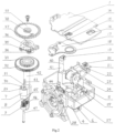
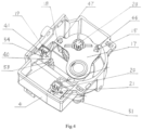
- an oscillation angle adjustment device for a fan including a motor (an alternating current motor 10 a direct current motor), a plastic gearbox housing 4, and a set of power transmission mechanism including a worm, a worm gear, a small gear of a worm gear shaft, and a large gear; a bearing sleeve positioning plate 17 is arranged between the small gear 28 of the worm gear shaft, and the large gear 32; a first inverted clasp 44 and a second inverted clasp 48 are arranged at a position of a bottom of the plastic gearbox housing 4 corresponding to an outer side of an addendum circle of the worm gear 27; a first clasp hole 15 and a second clasp hole 18 are arranged at a position of the bearing sleeve positioning plate 17 corresponding to the outer side of an addendum circle of the worm gear 27; and the first in
- a set of power transmission mechanism that is fixedly mounted in a screw-free manner is formed in the oscillation angle adjustment device for a fan of the present disclosure.
- the screw-free inverted clasp-clasp hole fixing manner is used for the bearing sleeve positioning plate 17 of the power transmission mechanism to replace a conventional screwing fixing technology in the prior art, so that screws are saved.
- no tools are used.
- An operator presses the bearing sleeve positioning plate 17 to the inverted clasps with hands to complete fixing, which improves the working efficiency. More importantly, this essentially eliminates a potential hazard of a quality accident caused during general assembling of a fan after delivery because screws are occasionally left in a gearbox finished product.
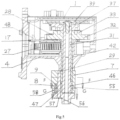
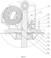
- a set of planetary gear train-crank mechanism composed of a sun gear 46, a plenary gear crank, a planetary frame 7 and a planetary shaft is arranged at a lower end of a mandrel 31 and a lower end of a hollow shaft 42; a circular arc reinforcing sleeve 8 is integrated on a lower end face of the planetary frame 7; a circular surface 58 of one end of the circular arc reinforcing sleeve is in sliding fit with a non-meshing portion of an addendum circle surface of the planetary gear 9; and another end 55 of the circular arc reinforcing sleeve keeps a space with an addendum circle of the sun gear 46.
- the semi-closed circular surface of one end of the circular arc reinforcing sleeve 8 can be used to restrain a single-ended cantilever structure of the planetary gear crank, to avoid dislocation.
- the addendum circle of the sun gear 46 is kept in an open clearance from another end 55 of the circular arc reinforcing sleeve, so that restricted extrusion damage from the planetary gear 9 to the sun gear 46 in the angle adjustment process is structurally eliminated, and the problem of braking of the sun gear 46 caused by the gyration of the planetary frame 7 and the circular arc reinforcing sleeve 8 is eliminated.
- a set of planetary gear train-crank mechanism in the oscillation angle adjustment device for a fan of the present disclosure is formed, which can eliminate reactive power loss during the angle adjustment, prolong the service lives of the three components of the planetary gear train-crank mechanism, and solve the problem of dislocation and slip of the single-ended cantilever structure of the planetary gear crank.
- a gap 43 is formed in a lower end of the hollow shaft 42; a bump 30 is formed on a wall body of a hollow shaft sleeve hole of the planetary frame 7; wall surfaces of two sides of the bump 30 are fixedly clamped into the gap 43 of the hollow shaft 42; an arc radial wall surface 59 of the bump 30 passes through the gap 43 in the lower end of the hollow shaft 42 to be in sliding fit with a body of the mandrel 31.
- the convenience of fixing the planetary frame 7 and the hollow shaft 42 is improved; the stability of contact with the circular surface during the gyration of the planetary frame 7 around the mandrel 31 in the angle adjustment process is also improved; a friction force of large-area gyration of the hollow shaft 42 and the mandrel 31 is also reduced; the reactive power consumption is reduced; and the service lives of the relevant components are prolonged.
- the planetary shaft is a rivet 47; a counterbore 56 is formed in a lower end surface of a planetary gear shaft hole 45 of the planetary gear crank; a diameter of the counterbore 56 is greater than that of a head 57 of the rivet, and a sinking depth of the counterbore 56 is greater than a thickness of the head 57 of the rivet; a diameter of a planetary shaft hole 29 formed in the planetary frame 7 is less than that of a body of the rivet; the body of the rivet passes through the counterbore 56 of the planetary gear 9 and the planetary gear shaft hole 45 in a sliding fit manner, and is then pressed into the planetary shaft hole 29 of the planetary frame 7 in an interference fit manner to achieve fastening; and after fastening, a cascade end surface of the head 57 of the rivet and a bottom end surface of the counterbore 56 of the planetary gear are in sliding fit.
- a longitudinal reference convex bar 60 is arranged on an outer wall of the circular arc reinforcing sleeve 8; a longitudinal zero-setting convex bar 61 is arranged on a crank body of the planetary gear crank; and when an eccentric distance of the planetary gear crank is located at a reference origin closest to a center distance of the sun gear 46, the longitudinal zero-setting convex bar 61 of the planetary gear crank is longitudinally linearly aligned with the longitudinal reference convex bar 60 of the circular arc reinforcing sleeve 8.
- a pawl seat 37, a pawl 34 and a bias spring 35 are arranged at an upper end of the mandrel 31;
- the large gear 32 is arranged at an upper end of the hollow shaft 42;
- a ratchet wheel 33 is concentrically integrated on an upper end face of the large gear 32, and an addendum circle is smaller than an addendum circle of the large gear 32;
- a profile of teeth of the ratchet wheel 33 is a non-involute tooth profile having a pressure angle greater than 30 degrees; and a cross section of a tooth 63 is trapezoid; and the pawl 34 abuts against the teeth of the ratchet wheel 33 with the non-involute tooth profile, to form a set of ratchet wheel-pawl clutch device.
- an effective load of the ratchet wheel-pawl clutch device is much greater than that of a large gear-pawl clutch device which has a pressure angle of 0-25 degrees only and has an involute tooth profile in the prior art. Furthermore, a larger pressure angle indicates a higher effective load. In this way, the structural disadvantages of low effective load and easy slip of the large gear-pawl clutch device in the prior art can be overcome, thus forming a set of clutch device that does not slip in a normal case.
- a control ratchet wheel 39 is arranged above the pawl seat 37; a via hole 38 is formed in the control ratchet wheel 39; a small cylinder 36 is arranged on the pawl 34 and can pass through the via hole 38 of the control ratchet wheel 39; a set of magnetic brake 24 with a brake ratchet 22 is arranged on an outer edge of the control ratchet wheel 39; and the magnetic brake device 24 is connected to an output end of an angle adjustment control chip 13 of a main control board through a wire 11, thus forming a set of electrically controlled clutch-brake operation mechanism.
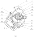
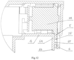
- the plastic gearbox housing 4 is provided with a longitudinal open slot 6 at the bottom, located on another side of a middle line of the worm, of the power transmission mechanism including the worm, the worm gear, the small gear of the worm gear shaft, and the large gear; a longitudinal mounting plate 5 is arranged at the bottom of the magnetic brake 24; the longitudinal mounting plate 5 of the magnetic brake 24 is inserted into the longitudinal open slot 6 of the plastic gearbox housing 4 to achieve close contact, so that the magnetic brake 24 is plugged into the plastic gearbox housing 4 in a hidden manner; an inverted buckle 65 is arranged on a side wall 64 of the longitudinal open slot; a through hole 25 is formed in the longitudinal mounting plate 5; and the through hole 25 of the longitudinal mounting plate 5 is inserted into the longitudinal open slot 6 along with the longitudinal mounting plate 5 to achieve inverted buckle-through hole clamping contact with the inverted buckle 65 on the side wall 64 of the longitudinal open slot.
- the magnetic brake 24 can be fixed in the plastic gearbox housing 4 with bare hands, without screws and tools.
- the labor and material cost of the conventional screwing technology for mounting the magnetic brake 24 in the prior art and the potential hazard that screws are left in a gearbox can be eliminated.
- the magnetic brake 24 is arranged at the bottom opposite to the plastic gearbox housing 4 in the hidden manner, instead of being mounted on the side wall of the gearbox housing 4, so that the assembling space is reduced, and the violation defect that the magnetic brake 24 is exposed from the side wall of the gearbox housing 4 is avoided.
- the through hole 25 of the longitudinal mounting plate 5 of the above magnetic brake 24 is a round through hole
- the inverted buckle 65 on the side wall 64 of the longitudinal open slot of the above plastic gearbox housing 4 is a round inverted buckle.
- An extension plate 66 is formed at a lower end of the round inverted buckle and extends out of the bottom end face of the longitudinal open slot 6.
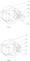
- a support-inverted clasp is arranged at a position of the plastic gearbox housing 4 close to an outgoing line 23 of the magnetic brake; the outgoing line 23 of the magnetic brake is connected to a magnetic trunking circuit board 21 and is connected with a magnetic trunking socket 20 on the board; a fourth clasp hole 50 and a fifth clasp hole 51 are formed in the magnetic trunking circuit board 21; and the fourth clasp hole 50 and the fifth clasp hole 51 of the magnetic trunking circuit board 21 are pressed into the support-inverted clasp of the plastic gearbox housing 4 to achieve inverted clasp-clasp hole fastening.
- a wire 12 of the angle adjustment control chip is provided with a magnetic trunking plug 3; and the magnetic trunking plug 3 is connected to the magnetic trunking socket 20 in a trunking plugging manner.
- the magnetic brake is fixed in the plastic gearbox housing 4 in an inverted clasp-clasp hole screw-free manner, so that an electrical control system is compact in configuration and convenient to mount, thereby forming a set of electrically controlled clutch-brake operation mechanism that complies with the production and operation regulations in the fan industry.
- a main power motor for air blowing and oscillation of the existing fan can be an alternating current motor or a direct current permanent magnet brushless motor. Due to different types of main power motors of the fan, an electrical signal sampling system in the oscillation angle adjustment device of a fan separately can separately adopt a corresponding electrical signal sampling system of the alternating current motor or a corresponding electrical signal sampling system of the direct current permanent magnet brushless motor.
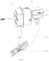
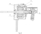
- Fig. 1 , Fig. 2 , Fig. 3 , Fig. 4 , Fig. 13, Fig. 14 , Fig. 15 and Fig. 16 when the main power motor of the fan is an alternating current motor 10, in the corresponding electrical signal sampling system of the alternating current motor, the motor is an alternating current motor 10.
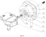
- a planar gap 75 is axially formed in a rotor shaft body 73, extending out of a housing 76 of the motor, of the rotor of the alternating current motor 10;
- the permanent magnet is a magnetic sheet 71;
- a plastic lantern ring 67 is arranged between the rotor shaft body 73 extending out of the housing 76 and the magnetic sheet 71;
- a magnet sleeving box 69 is arranged on an outer wall of the plastic lantern ring 67;
- a third inverted clasp 70 is arranged at an inlet of the magnet sleeving box 69;
- the magnetic sheet 71 presses, from the inlet of the magnet sleeving box 69, the third inverted clasp 70 to be inserted into the magnet sleeving box 69, to achieve fastening with the third inverted clasp 70, to form a set of magnetic sheet-plastic lantern ring assembling unit;
- seven circular arc convex bars 68 are arranged on an inner wall of the plastic
- the magnetic sheet 71 is plugged into the magnet sleeving box 69 of the plastic lantern ring 67 to form a set of elastic magnetic sheet-plastic lantern ring assembling unit, so that the assembling unit can sleeve a rotor shaft body 73 in a sliding manner from a rear end of the rotor shaft body 73 of the alternating current motor 10 extending out of the housing 76.
- the transverse clamping type clasp bump 72 on the wall body of the plastic lantern ring 67 is used to be clamped to the planar gap 75 of the rotor shaft body 73, which solves an assembling problem: Since the rotor of the alternating current motor 10 rotates at a high speed, a centrifugal force generated on a surface of the rotor shaft body 73 and the characteristic of a thermal expansion and cold contraction stress cause the magnetic sheet 71 to move and even fly out.
- This screw-free and glue-free sliding-mounting method is compatible with the industrial production technology and has the advantages of high efficiency and low cost.
- the rotor position sensing signal acquisition device is a hall sensor 74; the hall sensor 74 is mounted on an electrical signal trunking circuit board 41 and is connected to an electrical signal trunking socket 19 fixedly arranged to the electrical signal trunking circuit board 41; a third clasp hole 40 is formed in a side edge of the electrical signal trunking circuit board 41; a longitudinal clamping plate slot 54, a clamping plate bar 53 and a baffle plate-inverted clasp are arranged in the plastic gearbox housing 4; the electrical signal trunking circuit board 41 and the third clasp hole 40 thereof are plugged into the longitudinal clamping plate slot 54, the clamping plate bar 53 and baffle plate-inverted clasp of the plastic gearbox housing 4 from top to bottom, to achieve inverted clasp-clasp hole plugged fastening and fixing; after plugging and fixing, the hall sensor 74 on the electrical signal trunking circuit board 41 is located in the plastic gearbox housing 4, and corresponds to a radial clearance at the magnetic sheet 71
- the hall sensor 74 can be arranged in the plastic gearbox housing 4 that isolates a high-voltage environment, thus forming a set of alternating current motor 10 electrical signal sampling device, in which low- and high-voltage elements are isolated.
- the electrical signal trunking plug 2 arranged on the wire 12 of the angle adjustment control chip is connected to the electrical signal trunking socket 19 in the trunking plugging manner, to form the electrical signal sampling system of the alternating current motor of the present disclosure.
- the system is compatible with the industrial mounting technology.
- the electrical signal sampling system of the alternating current motor inputs a real-time detected electrical signal sampling value associated with and corresponding to a gyration action trajectory of the planetary gear crank into the angle adjustment control chip 13.
- the magnetic brake24 is controlled to be energized to be closed, and the brake ratchet 22 blocks the control ratchet wheel 39; the ratchet wheel-pawl clutch device is turned on to drive the planetary gear crank to gyrate to enter an angle adjustment state; when a difference between the electrical signal sampling value and a given value is zero, the angle adjustment control chip 13 sends a power-off instruction; the brake ratchet 22 of the magnetic brake 24 releases the control ratchet wheel, and the clutch device is closed; and the planetary gear crank is locked into an ordinary gear train according to a new set value.
- the alternating current fan oscillates to blow air according to a new oscillation angle range, to form the closed-loop electrically controlled oscillation angle adjustment device of the alternating current fan.
- the operation principle and path of the closed-loop electrically controlled oscillation angle adjustment device of the alternating current fan are publicly known technologies, and will not be described in detail.
- a cover plate 1 is arranged on the plastic gearbox housing 4; the cover plate 1 is provided with a second opening 16 and a first opening 14 in positions corresponding to the magnetic trunking socket 20 and the electrical signal trunking socket 19; and the cover plate 1 covers all components in the plastic gearbox housing 4, to achieve fastening combination with the plastic gearbox housing 4.
- a complete housing protection can be provided for the oscillation angle adjustment device product of a fan, which complies with the safety regulations and meets the industry regulations.
- a direct current fan embodiment with the oscillation angle adjustment device for a fan of the present disclosure is shown.
- the main power motor of the direct current fan is a 12v direct current permanent magnet brushless motor 77
- the oscillation angle adjustment device of the direct current fan of the present disclosure the remaining mechanisms are basically the same except that the corresponding electrical signal sampling system of the 12v direct current permanent magnet brushless motor 77 is different from the electrical signal sampling system of the alternating current fan.
- the motor is the 12v direct current permanent magnet brushless motor 77;
- the permanent magnet 84 is an existing permanent magnet of the rotor of the 12v direct current permanent magnet brushless motor;
- the rotor position sensing signal acquisition device is an existing hall sensor 81 of the 12v direct current permanent magnet brushless motor;
- an existing electrical signal wire 79 of the existing hall sensor 81 of 12v direct current permanent magnet brushless motor is connected to the input end of the angle adjustment control chip 13 via a connecting line.
- the 12v direct current permanent magnet brushless motor 77 does not have a direct current low voltage inside to break down an electrical environment of the existing hall sensor 81 of the 12v direct current permanent magnet brushless motor, so that the electrical signal sampling system of the 12v direct current permanent magnet brushless motor 77 in the present disclosure can be formed as long as the connecting line connected to the input end of the angle adjustment control chip 13 is additionally arranged at an output end of the electrical signal wire 79 of the existing hall sensor 81 of the 12v direct current permanent magnet brushless motor.
- the electrical signal sampling system of the 12v direct current permanent magnet brushless motor 77 is connected to the input end of the angle adjustment control chip 13, and the output end of the angle adjustment control chip 13 is connected to the magnetic brake 24, to form a closed-loop electrically controlled oscillation angle adjustment device of a fan with the 12v direct current permanent magnet brushless motor, so that the planetary gear train-crank can be operated to be adjusted according to a new set value to achieve automatic adjustment of an oscillation angle of the direct current fan.
- the adjustment path and principle of the closed-loop electrically controlled planetary gear train-crank have been described in the technical solution of the alternating current fan, and will not be repeated here.
- a specific clearance between another end of the circular arc reinforcing sleeve integrated on the lower end face of the planetary frame and the addendum circle of the sun gear is not limited to a circular arc clearance of another end shown in the above embodiment greater than a radius of the addendum circle of the sun gear, a rectangular clearance of another end greater than a diameter of the addendum circle of the sun gear, a specially-shaped clearance of another end greater than a diameter of the addendum circle of the sun gear to facilitate machine, or a vacant open clearance of another end from the non-meshing portion of the addendum circle of the sun gear.
Landscapes
- Engineering & Computer Science (AREA)
- Mechanical Engineering (AREA)
- General Engineering & Computer Science (AREA)
- Power Engineering (AREA)
- Physics & Mathematics (AREA)
- Geometry (AREA)
- Microelectronics & Electronic Packaging (AREA)
- Connection Of Motors, Electrical Generators, Mechanical Devices, And The Like (AREA)
- Structures Of Non-Positive Displacement Pumps (AREA)
- Retarders (AREA)
Applications Claiming Priority (2)
| Application Number | Priority Date | Filing Date | Title |
|---|---|---|---|
| CN202011155032.0A CN114483625B (zh) | 2020-10-26 | 2020-10-26 | 一种电风扇摇头摆角调节装置及应用其的电风扇 |
| PCT/CN2021/100245 WO2022088691A1 (fr) | 2020-10-26 | 2021-06-16 | Dispositif de réglage d'angle de pivotement pour tête oscillante de ventilateur électrique, et ventilateur électrique l'utilisant |
Publications (2)
| Publication Number | Publication Date |
|---|---|
| EP4234941A1 true EP4234941A1 (fr) | 2023-08-30 |
| EP4234941A4 EP4234941A4 (fr) | 2024-05-15 |
Family
ID=81381832
Family Applications (1)
| Application Number | Title | Priority Date | Filing Date |
|---|---|---|---|
| EP21884432.2A Pending EP4234941A4 (fr) | 2020-10-26 | 2021-06-16 | Dispositif de réglage d'angle de pivotement pour tête oscillante de ventilateur électrique, et ventilateur électrique l'utilisant |
Country Status (5)
| Country | Link |
|---|---|
| US (1) | US12163527B2 (fr) |
| EP (1) | EP4234941A4 (fr) |
| JP (1) | JP7587317B2 (fr) |
| CN (1) | CN114483625B (fr) |
| WO (1) | WO2022088691A1 (fr) |
Families Citing this family (3)
| Publication number | Priority date | Publication date | Assignee | Title |
|---|---|---|---|---|
| CN116094248B (zh) * | 2022-12-16 | 2024-04-26 | 宜兴华永电机有限公司 | 一种电磁齿轮箱散热机构 |
| CN116489982B (zh) * | 2023-06-21 | 2023-09-29 | 国网天津市电力公司城东供电分公司 | 一种电力数据采集装置 |
| CN118017768B (zh) * | 2024-04-08 | 2024-06-04 | 江苏中奕和创智能科技有限公司 | 一种具有包裹式直流外出风冷却机构的发电机组 |
Family Cites Families (14)
| Publication number | Priority date | Publication date | Assignee | Title |
|---|---|---|---|---|
| US2341220A (en) * | 1940-11-14 | 1944-02-08 | Gilbert Co A C | Fan oscillator with motor carried clutch control |
| CN1072246A (zh) * | 1991-11-14 | 1993-05-19 | 新疆石河子八一棉纺织厂 | 一种棘轮机构 |
| CN2378559Y (zh) * | 1998-12-04 | 2000-05-17 | 李振刚 | 行星轮系摆角调节增强装置 |
| JP2001342990A (ja) * | 2000-05-31 | 2001-12-14 | Toshiba Eng Co Ltd | 扇風機および回転動を360度以内の回動に変換する機構 |
| US6468036B1 (en) * | 2000-06-27 | 2002-10-22 | Jiajun Song | Adjustable crank of swinging mechanism |
| CN100489314C (zh) * | 2000-09-30 | 2009-05-20 | 蒋亮健 | 电风扇摇头摆角调节装置 |
| CN1450270A (zh) * | 2002-04-11 | 2003-10-22 | 蒋亮健 | 行星轮系摆角调节增强装置 |
| CN1936339B (zh) * | 2005-09-19 | 2010-07-28 | 蒋亮健 | 电风扇摆角调节控制装置 |
| CN2853741Y (zh) * | 2005-09-30 | 2007-01-03 | 莫魁 | 矿用提升小绞车的无级调速装置 |
| CN202483962U (zh) * | 2011-11-17 | 2012-10-10 | 廖顺得 | 一种风扇 |
| CN206211897U (zh) * | 2016-11-24 | 2017-05-31 | 北京大豪科技股份有限公司 | 交流伺服电机控制系统 |
| CN109139520B (zh) * | 2017-06-16 | 2022-03-08 | 蒋亮健 | 电风扇摇头摆角调节装置 |
| CN208535113U (zh) * | 2018-06-06 | 2019-02-22 | 中国第一汽车股份有限公司 | 一种分体式汽车传动器差速器总成 |
| CN111255721A (zh) * | 2018-12-03 | 2020-06-09 | 蒋亮健 | 电风扇摆角调节采样装置 |
-
2020
- 2020-10-26 CN CN202011155032.0A patent/CN114483625B/zh active Active
-
2021
- 2021-06-16 WO PCT/CN2021/100245 patent/WO2022088691A1/fr not_active Ceased
- 2021-06-16 JP JP2023548988A patent/JP7587317B2/ja active Active
- 2021-06-16 EP EP21884432.2A patent/EP4234941A4/fr active Pending
- 2021-06-16 US US18/250,211 patent/US12163527B2/en active Active
Also Published As
| Publication number | Publication date |
|---|---|
| CN114483625B (zh) | 2023-07-04 |
| WO2022088691A1 (fr) | 2022-05-05 |
| JP7587317B2 (ja) | 2024-11-20 |
| CN114483625A (zh) | 2022-05-13 |
| JP2023546737A (ja) | 2023-11-07 |
| US20230392604A1 (en) | 2023-12-07 |
| EP4234941A4 (fr) | 2024-05-15 |
| US12163527B2 (en) | 2024-12-10 |
Similar Documents
| Publication | Publication Date | Title |
|---|---|---|
| US12163527B2 (en) | Swing angle adjustment device for electric fan oscillating head, and electric fan applying same | |
| CN201063481Y (zh) | 制动型电动推杆 | |
| CN103270342B (zh) | 线性致动器 | |
| CN110154922B (zh) | 用于调节显示终端的执行机构和车辆 | |
| DE102006047269A1 (de) | Umrichtermotor | |
| DE19721528A1 (de) | Elektrische Maschine und Verfahren zur Montage der elektrischen Maschine an einem Aggregat | |
| CN102856093B (zh) | 具有机械限位、强制断开及动态监控的凸轮控制器 | |
| RU2573123C1 (ru) | Ограничитель крутящего момента привода клапана | |
| CN209176716U (zh) | 一种电液转辙机锁闭杆组件 | |
| CN105448554A (zh) | 一种大角度输出电动机操动机构 | |
| KR102596006B1 (ko) | 전동 공구 부착 부분 | |
| CN110143172A (zh) | 用于调节显示终端的执行机构和车辆 | |
| EP1733152B1 (fr) | Dispositif de freinage pour appareils entraines par moteur electrique | |
| CN108061191B (zh) | 一种阀用电动机构 | |
| KR200433879Y1 (ko) | 사이클로 감속기 | |
| US20150148185A1 (en) | Linear Travel Structure of Electrical Operating Device | |
| CN107425635A (zh) | 一体式刹车电机 | |
| KR20050086442A (ko) | 축용 루퍼 장치 | |
| CN204130370U (zh) | 大角度输出电动机操动机构 | |
| CN208180917U (zh) | 用于调节显示终端的执行机构和车辆 | |
| CN110143170A (zh) | 用于调节显示终端的执行机构和车辆 | |
| CN218102867U (zh) | 一种纠偏电动执行器 | |
| CN217315902U (zh) | 一种高速电主轴编码器装置 | |
| CN210350949U (zh) | 一种可断电制动的无刷无齿电机 | |
| CN119891629A (zh) | 一种防堵转防爆电动执行机构 |
Legal Events
| Date | Code | Title | Description |
|---|---|---|---|
| STAA | Information on the status of an ep patent application or granted ep patent |
Free format text: STATUS: THE INTERNATIONAL PUBLICATION HAS BEEN MADE |
|
| PUAI | Public reference made under article 153(3) epc to a published international application that has entered the european phase |
Free format text: ORIGINAL CODE: 0009012 |
|
| STAA | Information on the status of an ep patent application or granted ep patent |
Free format text: STATUS: REQUEST FOR EXAMINATION WAS MADE |
|
| 17P | Request for examination filed |
Effective date: 20230519 |
|
| AK | Designated contracting states |
Kind code of ref document: A1 Designated state(s): AL AT BE BG CH CY CZ DE DK EE ES FI FR GB GR HR HU IE IS IT LI LT LU LV MC MK MT NL NO PL PT RO RS SE SI SK SM TR |
|
| DAV | Request for validation of the european patent (deleted) | ||
| DAX | Request for extension of the european patent (deleted) | ||
| A4 | Supplementary search report drawn up and despatched |
Effective date: 20240412 |
|
| RIC1 | Information provided on ipc code assigned before grant |
Ipc: H02K 7/116 20060101ALI20240408BHEP Ipc: F04D 25/10 20060101AFI20240408BHEP |