EP4234954B1 - Befestigungsklammeranordnung mit verriegelungsarmen - Google Patents
Befestigungsklammeranordnung mit verriegelungsarmen Download PDFInfo
- Publication number
- EP4234954B1 EP4234954B1 EP23158365.9A EP23158365A EP4234954B1 EP 4234954 B1 EP4234954 B1 EP 4234954B1 EP 23158365 A EP23158365 A EP 23158365A EP 4234954 B1 EP4234954 B1 EP 4234954B1
- Authority
- EP
- European Patent Office
- Prior art keywords
- pair
- locking arms
- fastener clip
- doghouse
- slot
- Prior art date
- Legal status (The legal status is an assumption and is not a legal conclusion. Google has not performed a legal analysis and makes no representation as to the accuracy of the status listed.)
- Active
Links
Images



Classifications
-
- F—MECHANICAL ENGINEERING; LIGHTING; HEATING; WEAPONS; BLASTING
- F16—ENGINEERING ELEMENTS AND UNITS; GENERAL MEASURES FOR PRODUCING AND MAINTAINING EFFECTIVE FUNCTIONING OF MACHINES OR INSTALLATIONS; THERMAL INSULATION IN GENERAL
- F16B—DEVICES FOR FASTENING OR SECURING CONSTRUCTIONAL ELEMENTS OR MACHINE PARTS TOGETHER, e.g. NAILS, BOLTS, CIRCLIPS, CLAMPS, CLIPS OR WEDGES; JOINTS OR JOINTING
- F16B5/00—Joining sheets or plates, e.g. panels, to one another or to strips or bars parallel to them
- F16B5/06—Joining sheets or plates, e.g. panels, to one another or to strips or bars parallel to them by means of clamps or clips
- F16B5/0607—Joining sheets or plates, e.g. panels, to one another or to strips or bars parallel to them by means of clamps or clips joining sheets or plates to each other
- F16B5/0621—Joining sheets or plates, e.g. panels, to one another or to strips or bars parallel to them by means of clamps or clips joining sheets or plates to each other in parallel relationship
- F16B5/0657—Joining sheets or plates, e.g. panels, to one another or to strips or bars parallel to them by means of clamps or clips joining sheets or plates to each other in parallel relationship at least one of the plates providing a raised structure, e.g. of the doghouse type, for connection with the clamps or clips of the other plate
Definitions
- the invention relates generally to devices for fastening together two or more objects.
- a number of devices and fasteners are currently available for fastening objects, such as body panels and automobile interior trim piece panels to the chassis of a vehicle, for example.
- a body panel may refer to, for example, any interior or exterior body panel on a vehicle, a plastic interior trim piece, headliner, or any interior trim piece.
- the panel may be any suitable exterior body panel, such as a fender, bumper, quarter panel, or door panel.
- the chassis of the vehicle may include any substrate, plate, body panel, structural framework, chassis component or subcomponent, wall, or any suitable object.
- Publication US 9,670,947 discloses a trim retainer assembly having a clip portion with a base and a molded housing having a keyhole and an opening.
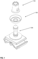
- Figure 1 is an exploded view of a fastener clip assembly, in accordance with some embodiments.
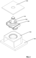
- Figure 2 is an exploded view of a fastener clip assembly, a body panel, and a chassis, in accordance with some embodiments.
- the fastener clip assembly comprises cap/grommet 1100 and pin/pin retainer 1200.
- Pin 1200 is configured to engage and secure itself on cap 1100 based at least upon cap 1100 being configured to fit over pin 1200 and into an interlocked position for the pin and the cap.
- the cap/pin assembly may be configured to attach to a slot/hole in chassis 1500 on one end by attaching the cap to the chassis slot and the pin to the cap, for example. On the other end, the assembly may be configured to attach to a doghouse or similar object in panel 1400.
- Pin 1200 may be configured to be coupled to a doghouse by being pressed into a slot in doghouse 1450 of panel 1400, for example.
- the doghouse may be coupled to panel 1400 by various means such as an adhesive, the doghouse may be molded onto panel 1400, etc.
- the two-piece assembly may be configured to retain various trim panels (such as panel 1400) to a car chassis (such as chassis 1500), for example, based at least upon the two-piece assembly being configured to couple to both the panel and the chassis.
- the fastener clip assembly may be configured to join various other comparable pairs of objects to each other.
- optional seal component 1300 is configured to attach over pin 1200 and to form a seal against the surface of chassis 1500 when the pin/cap assembly is attached to chassis 1500. In some embodiments, forming a seal against chassis surface 1500 prevents water, dirt, and other debris from entering through the chassis slot from the outside to the inside of the chassis. In some embodiments, choosing whether to use seal component 1300 may depend on the environment (such as the amount of water, dirt, etc. present).
- pin/ cap shown here is only one example of a structure/method to couple the fastener clip to the chassis.
- cap 1100 is configured to be interlocked with pin 1200, and the two-part assembly is configured to engage and attach to a slot in a chassis and in addition engage and attach to a panel.
- cap 1100 comprises top portion 10 from which cylinder 15 extends, ending in cap foot 25.
- Cap 1100 may also include four crown portions 40 near top portion 10. Crown portions 40 are configured to bend and then snap back into position as the head of pin 1200 is inserted into cap 1100. Crown portions 40 are configured to engage a bottom surface of the head of the pin to lock the pin to the cap once the pin is inserted into the cap.
- small slots 42 may be placed between crown portions 40.
- the small slots may be configured to facilitate the bending of crown portions 40, such that the crown portions 40 can bend enough to allow for the engagement of the head of pin 1200.
- cap 1100 includes one or more tabs 35 (two are present in the shown embodiment) that are configured to collapse as cap 1100 is pushed into a slot in a chassis and then expand again on the other side of the chassis slot.
- the bottom sides 20 of tabs 35 are configured to secure cap 1100 to the slot in the chassis.
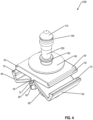
- Figure 4 is a view of a pin of a fastener clip assembly with a locking panel attachment, in accordance with some embodiments.
- Figure 5 is a view of a fastener clip assembly in locked position, in accordance with some embodiments.
- pin/cap shown here is only one example of a structure/method to couple the fastener clip to the chassis.
- a removable seal may be configured to slide over pin 1200 through rim 250.
- the removable seal may be secured between base disk 140 and seal retainer 150.
Landscapes
- Engineering & Computer Science (AREA)
- General Engineering & Computer Science (AREA)
- Mechanical Engineering (AREA)
- Insertion Pins And Rivets (AREA)
- Connection Of Plates (AREA)
- Clamps And Clips (AREA)
Claims (14)
- Befestigungsklammer, umfassend:ein oberen Abschnitt (10), wobei der obere Abschnitt (10) konfiguriert ist, um mit einem Chassis (1500) verbunden zu werden,einen unteren Abschnitt, wobei der untere Abschnitt Folgendes umfasst:eine Plattform (50);mindestens ein Paar von Verriegelungsarmen (60), die über ein Paar Scharniere (65) mit der Plattform (50) gekoppelt sind, wobei die Scharniere (65) konfiguriert sind, um eine relative Drehung zwischen den Verriegelungsarmen (60) und der Plattform (50) zu ermöglichen;mindestens ein Paar Füße (80), die mit den Verriegelungsarmen (60) verbunden und konfiguriert sind, um mit den Verriegelungsarmen (60) zu drehen,wobei die Füße (80) konfiguriert sind, um teilweise in einen Schlitz in einer Einsatzöffnung (1450) eingesetzt werden können, und die Füße (80) zumindest darauf basierend, dass die Verriegelungsarme (60) gedreht werden, konfiguriert sind, um in den Schlitz in der Einsatzöffnung (1450) zu drehen und den unteren Abschnitt mit der Einsatzöffnung (1450) zu koppeln,wobei die Verriegelungsarme (60) konfiguriert sind, um zumindest darauf basierend, dass die Verriegelungsarme (60) eine obere Fläche der Einsatzöffnung (1450) eingreifen, wenn der Befestigungsclip in den Schlitz in der Einsatzöffnung (1450) geschoben wird, gedreht zu werden,wobei die Verriegelungsarme (60) konfiguriert sind, um am Ende der Drehung mit der Plattform (50) gekoppelt zu werden.
- Befestigungsklammer nach Anspruch 1, wobei das Scharnierpaar (65) ein Paar Filmscharniere ist.
- Befestigungsklammer nach Anspruch 2, wobei das Paar beweglicher Scharniere (65) aus dem gleichen Material wie die Plattform (50) und das Paar Verriegelungsarme (60) gefertigt ist.
- Befestigungsklammer nach Anspruch 1, wobei der untere Abschnitt ein Paar Federfinger (75) zwischen dem Paar Verriegelungsarme (60) und dem Paar Füße (80) umfasst, wobei das Paar Federfinger (75) konfiguriert ist, um die Befestigungsklammer über dem Schlitz in der Einsatzöffnung (1450) zentriert zu halten, zumindest basierend darauf, dass das Paar von Federfinger (75) konfiguriert ist, um federnd gegen die Seiten des Schlitzes in der Einsatzöffnung (1450) zu drücken.
- Befestigungsklammer nach Anspruch 4, wobei die Federfinger (75) konfiguriert sind, um ein gewisses Maß an Beweglichkeit zwischen der Befestigungsklammer und der Einsatzöffnung (1450) zumindest basierend auf einer Federwirkung der Federfinger (75) zu ermöglichen.
- Befestigungsklammer nach Anspruch 1, wobei das Paar Verriegelungsarme (60) ein Paar Haken (70) umfasst, die konfiguriert sind, um die Verriegelungsarme (60) an der Plattform (50) zu verriegeln, zumindest basierend darauf, dass das Paar Haken (70) konfiguriert ist, um in ein entsprechendes Paar Lippen (55) an der Plattform (50) einzugreifen.
- Befestigungsklammer nach Anspruch 6, wobei sich das Paar Verriegelungsarme (60) und das entsprechende Paar Lippen (55) über eine Breite der Plattform (50) erstreckt.
- Befestigungsklammeranordnung, umfassend:ein Chassis (1500);eine Einsatzöffnung (1450), umfassend einen Schlitz;eine Befestigungsklammer, umfassend:einen oberen Abschnitt (10), wobei der obere Abschnitt (10) konfiguriert ist, um mit dem Chassis (1500) verbunden zu werden,einen unteren Abschnitt, wobei der untere Abschnitt Folgendes umfasst:eine Plattform (50);mindestens ein Paar von Verriegelungsarmen (60), die über ein Paar Scharniere (65) mit der Plattform (50) gekoppelt sind, wobei die Scharniere (65) konfiguriert sind, um eine relative Drehung zwischen den Verriegelungsarmen (60) und der Plattform (50) zu ermöglichen;mindestens ein Paar Füße (80), die mit den Verriegelungsarmen (60) verbunden und konfiguriert sind, um mit den Verriegelungsarmen (60) zu drehen,wobei die Füße (80) konfiguriert sind, um teilweise in den Schlitz in der Einsatzöffnung (1450) eingeführt werden, und die Füße (80) zumindest basierend auf der Drehung der Verriegelungsarme (60) konfiguriert sind, um sich in den Schlitz in der Einsatzöffnung (1450) drehen und den unteren Abschnitt mit der Einsatzöffnung (1450) verbinden,wobei die Verriegelungsarme (60) konfiguriert sind, um zumindest darauf basierend, dass die Verriegelungsarme (60) eine obere Fläche der Einsatzöffnung (1450) eingreifen, wenn der Befestigungsclip in den Schlitz in der Einsatzöffnung (1450) geschoben wird, gedreht zu werden,wobei die Verriegelungsarme (60) konfiguriert sind, um am Ende der Drehung mit der Plattform (50) gekoppelt zu werden.
- Befestigungsklammeranordnung nach Anspruch 8, wobei das Paar Scharniere (65) ein Paar Filmscharniere ist.
- Befestigungsklammeranordnung nach Anspruch 9, wobei das Paar beweglicher Scharniere (65) aus dem gleichen Material wie die Plattform (50) und das Paar Verriegelungsarme (60) gefertigt ist.
- Befestigungsklammeranordnung nach Anspruch 8, wobei der untere Abschnitt ein Paar Federfinger (75) zwischen dem Paar Verriegelungsarme (60) und dem Paar Füße (80) umfasst, wobei das Paar Federfinger (75) konfiguriert ist, um die Befestigungsklammer über dem Schlitz in der Einsatzöffnung (1450) zentriert zu halten, zumindest basierend darauf, dass das Paar von Federfinger (75) konfiguriert ist, um federnd gegen die Seiten des Schlitzes in der Einsatzöffnung (1450) zu drücken.
- Befestigungsklammeranordnung nach Anspruch 8, wobei die Federfinger (75) konfiguriert sind, um ein gewisses Maß an Beweglichkeit zwischen der Befestigungsklammer und der Einsatzöffnung (1450) zumindest basierend auf einer Federwirkung der Federfinger (75) zu ermöglichen.
- Befestigungsklammeranordnung nach Anspruch 8, wobei das Paar Verriegelungsarme (60) ein Paar Haken (70) umfasst, die konfiguriert sind, um die Verriegelungsarme (60) an der Plattform (50) zu verriegeln, zumindest basierend darauf, dass das Paar Haken (70) konfiguriert ist, um in ein entsprechendes Paar Lippen (55) an der Plattform (50) einzugreifen.
- Befestigungsklammeranordnung nach Anspruch 13, wobei sich das Paar Verriegelungsarme (60) und das entsprechende Paar Lippen (55) über eine Breite der Plattform (50) erstreckt.
Applications Claiming Priority (2)
| Application Number | Priority Date | Filing Date | Title |
|---|---|---|---|
| US202263314474P | 2022-02-27 | 2022-02-27 | |
| US18/106,991 US12006966B2 (en) | 2020-11-13 | 2023-02-07 | Fastener clip assembly with locking arms |
Publications (2)
| Publication Number | Publication Date |
|---|---|
| EP4234954A1 EP4234954A1 (de) | 2023-08-30 |
| EP4234954B1 true EP4234954B1 (de) | 2025-07-09 |
Family
ID=85382833
Family Applications (1)
| Application Number | Title | Priority Date | Filing Date |
|---|---|---|---|
| EP23158365.9A Active EP4234954B1 (de) | 2022-02-27 | 2023-02-23 | Befestigungsklammeranordnung mit verriegelungsarmen |
Country Status (2)
| Country | Link |
|---|---|
| EP (1) | EP4234954B1 (de) |
| ES (1) | ES3041852T3 (de) |
Family Cites Families (2)
| Publication number | Priority date | Publication date | Assignee | Title |
|---|---|---|---|---|
| JPH0452486Y2 (de) * | 1987-05-27 | 1992-12-10 | ||
| CA2911806C (en) * | 2014-11-10 | 2023-02-28 | Theodore J. Bachelder | Trim retainer - stab clip |
-
2023
- 2023-02-23 EP EP23158365.9A patent/EP4234954B1/de active Active
- 2023-02-23 ES ES23158365T patent/ES3041852T3/es active Active
Also Published As
| Publication number | Publication date |
|---|---|
| ES3041852T3 (en) | 2025-11-17 |
| EP4234954A1 (de) | 2023-08-30 |
Similar Documents
| Publication | Publication Date | Title |
|---|---|---|
| US12006966B2 (en) | Fastener clip assembly with locking arms | |
| US4932105A (en) | Self locking attaching system | |
| US10006479B2 (en) | Fastener clip assembly with funnel guide | |
| KR101927389B1 (ko) | 루프 배수구 몰딩 리테이너 조립체 | |
| US8776326B2 (en) | Panel connection snap assembly | |
| US7614836B2 (en) | Arrangements for attaching components to surfaces | |
| CN106979201B (zh) | 具有漏斗引导件的紧固件夹具组件 | |
| US10995783B2 (en) | Fastener clip assembly with a dome and limiters | |
| US20190017527A1 (en) | Sealed Fastener Clip with One-Step Assembly | |
| US4850773A (en) | Clip | |
| US8322110B2 (en) | Trim flap-like closeout edge attachment | |
| US20080141501A1 (en) | Clip | |
| US11773887B2 (en) | Fastener clip assembly with expandable cap | |
| US5567098A (en) | Releasable fastener assembly | |
| KR20100122856A (ko) | 체결구 | |
| EP4234954A1 (de) | Befestigungsklammeranordnung mit verriegelungsarmen | |
| CN110645240A (zh) | 用于将装饰面板固定到支撑基板的紧固系统 | |
| EP4342652A2 (de) | Befestigungsklammeranordnung zum formen und einrasten von klingen | |
| JP3491266B2 (ja) | 止め具 | |
| US6030030A (en) | Exterior body side sill molding attachment for a motor vehicle and related method | |
| CN116044872B (zh) | 紧固件夹组件和紧固件夹系统 | |
| CN220151667U (zh) | 紧固件夹和紧固件夹组件 | |
| US6829812B2 (en) | Grab handle assembly system and method | |
| JPH0139922Y2 (de) | ||
| JPS6490Y2 (de) |
Legal Events
| Date | Code | Title | Description |
|---|---|---|---|
| PUAI | Public reference made under article 153(3) epc to a published international application that has entered the european phase |
Free format text: ORIGINAL CODE: 0009012 |
|
| STAA | Information on the status of an ep patent application or granted ep patent |
Free format text: STATUS: THE APPLICATION HAS BEEN PUBLISHED |
|
| AK | Designated contracting states |
Kind code of ref document: A1 Designated state(s): AL AT BE BG CH CY CZ DE DK EE ES FI FR GB GR HR HU IE IS IT LI LT LU LV MC ME MK MT NL NO PL PT RO RS SE SI SK SM TR |
|
| P01 | Opt-out of the competence of the unified patent court (upc) registered |
Effective date: 20231115 |
|
| STAA | Information on the status of an ep patent application or granted ep patent |
Free format text: STATUS: REQUEST FOR EXAMINATION WAS MADE |
|
| 17P | Request for examination filed |
Effective date: 20240207 |
|
| RBV | Designated contracting states (corrected) |
Designated state(s): AL AT BE BG CH CY CZ DE DK EE ES FI FR GB GR HR HU IE IS IT LI LT LU LV MC ME MK MT NL NO PL PT RO RS SE SI SK SM TR |
|
| STAA | Information on the status of an ep patent application or granted ep patent |
Free format text: STATUS: EXAMINATION IS IN PROGRESS |
|
| 17Q | First examination report despatched |
Effective date: 20240625 |
|
| GRAP | Despatch of communication of intention to grant a patent |
Free format text: ORIGINAL CODE: EPIDOSNIGR1 |
|
| STAA | Information on the status of an ep patent application or granted ep patent |
Free format text: STATUS: GRANT OF PATENT IS INTENDED |
|
| INTG | Intention to grant announced |
Effective date: 20250318 |
|
| GRAS | Grant fee paid |
Free format text: ORIGINAL CODE: EPIDOSNIGR3 |
|
| GRAA | (expected) grant |
Free format text: ORIGINAL CODE: 0009210 |
|
| STAA | Information on the status of an ep patent application or granted ep patent |
Free format text: STATUS: THE PATENT HAS BEEN GRANTED |
|
| AK | Designated contracting states |
Kind code of ref document: B1 Designated state(s): AL AT BE BG CH CY CZ DE DK EE ES FI FR GB GR HR HU IE IS IT LI LT LU LV MC ME MK MT NL NO PL PT RO RS SE SI SK SM TR |
|
| REG | Reference to a national code |
Ref country code: GB Ref legal event code: FG4D |
|
| REG | Reference to a national code |
Ref country code: CH Ref legal event code: EP |
|
| REG | Reference to a national code |
Ref country code: IE Ref legal event code: FG4D |
|
| REG | Reference to a national code |
Ref country code: DE Ref legal event code: R096 Ref document number: 602023004597 Country of ref document: DE |
|
| REG | Reference to a national code |
Ref country code: NL Ref legal event code: MP Effective date: 20250709 |
|
| REG | Reference to a national code |
Ref country code: ES Ref legal event code: FG2A Ref document number: 3041852 Country of ref document: ES Kind code of ref document: T3 Effective date: 20251117 |
|
| PG25 | Lapsed in a contracting state [announced via postgrant information from national office to epo] |
Ref country code: PT Free format text: LAPSE BECAUSE OF FAILURE TO SUBMIT A TRANSLATION OF THE DESCRIPTION OR TO PAY THE FEE WITHIN THE PRESCRIBED TIME-LIMIT Effective date: 20251110 |
|
| PG25 | Lapsed in a contracting state [announced via postgrant information from national office to epo] |
Ref country code: NL Free format text: LAPSE BECAUSE OF FAILURE TO SUBMIT A TRANSLATION OF THE DESCRIPTION OR TO PAY THE FEE WITHIN THE PRESCRIBED TIME-LIMIT Effective date: 20250709 |
|
| REG | Reference to a national code |
Ref country code: AT Ref legal event code: MK05 Ref document number: 1812042 Country of ref document: AT Kind code of ref document: T Effective date: 20250709 |
|
| PG25 | Lapsed in a contracting state [announced via postgrant information from national office to epo] |
Ref country code: IS Free format text: LAPSE BECAUSE OF FAILURE TO SUBMIT A TRANSLATION OF THE DESCRIPTION OR TO PAY THE FEE WITHIN THE PRESCRIBED TIME-LIMIT Effective date: 20251109 |
|
| PG25 | Lapsed in a contracting state [announced via postgrant information from national office to epo] |
Ref country code: NO Free format text: LAPSE BECAUSE OF FAILURE TO SUBMIT A TRANSLATION OF THE DESCRIPTION OR TO PAY THE FEE WITHIN THE PRESCRIBED TIME-LIMIT Effective date: 20251009 |
|
| REG | Reference to a national code |
Ref country code: LT Ref legal event code: MG9D |
|
| PG25 | Lapsed in a contracting state [announced via postgrant information from national office to epo] |
Ref country code: AT Free format text: LAPSE BECAUSE OF FAILURE TO SUBMIT A TRANSLATION OF THE DESCRIPTION OR TO PAY THE FEE WITHIN THE PRESCRIBED TIME-LIMIT Effective date: 20250709 |
|
| PG25 | Lapsed in a contracting state [announced via postgrant information from national office to epo] |
Ref country code: FI Free format text: LAPSE BECAUSE OF FAILURE TO SUBMIT A TRANSLATION OF THE DESCRIPTION OR TO PAY THE FEE WITHIN THE PRESCRIBED TIME-LIMIT Effective date: 20250709 |
|
| PG25 | Lapsed in a contracting state [announced via postgrant information from national office to epo] |
Ref country code: HR Free format text: LAPSE BECAUSE OF FAILURE TO SUBMIT A TRANSLATION OF THE DESCRIPTION OR TO PAY THE FEE WITHIN THE PRESCRIBED TIME-LIMIT Effective date: 20250709 |
|
| PG25 | Lapsed in a contracting state [announced via postgrant information from national office to epo] |
Ref country code: GR Free format text: LAPSE BECAUSE OF FAILURE TO SUBMIT A TRANSLATION OF THE DESCRIPTION OR TO PAY THE FEE WITHIN THE PRESCRIBED TIME-LIMIT Effective date: 20251010 |
|
| PG25 | Lapsed in a contracting state [announced via postgrant information from national office to epo] |
Ref country code: SE Free format text: LAPSE BECAUSE OF FAILURE TO SUBMIT A TRANSLATION OF THE DESCRIPTION OR TO PAY THE FEE WITHIN THE PRESCRIBED TIME-LIMIT Effective date: 20250709 |
|
| PG25 | Lapsed in a contracting state [announced via postgrant information from national office to epo] |
Ref country code: LV Free format text: LAPSE BECAUSE OF FAILURE TO SUBMIT A TRANSLATION OF THE DESCRIPTION OR TO PAY THE FEE WITHIN THE PRESCRIBED TIME-LIMIT Effective date: 20250709 |
|
| PG25 | Lapsed in a contracting state [announced via postgrant information from national office to epo] |
Ref country code: BG Free format text: LAPSE BECAUSE OF FAILURE TO SUBMIT A TRANSLATION OF THE DESCRIPTION OR TO PAY THE FEE WITHIN THE PRESCRIBED TIME-LIMIT Effective date: 20250709 Ref country code: PL Free format text: LAPSE BECAUSE OF FAILURE TO SUBMIT A TRANSLATION OF THE DESCRIPTION OR TO PAY THE FEE WITHIN THE PRESCRIBED TIME-LIMIT Effective date: 20250709 |
|
| PG25 | Lapsed in a contracting state [announced via postgrant information from national office to epo] |
Ref country code: RS Free format text: LAPSE BECAUSE OF FAILURE TO SUBMIT A TRANSLATION OF THE DESCRIPTION OR TO PAY THE FEE WITHIN THE PRESCRIBED TIME-LIMIT Effective date: 20251009 |
|
| PG25 | Lapsed in a contracting state [announced via postgrant information from national office to epo] |
Ref country code: SM Free format text: LAPSE BECAUSE OF FAILURE TO SUBMIT A TRANSLATION OF THE DESCRIPTION OR TO PAY THE FEE WITHIN THE PRESCRIBED TIME-LIMIT Effective date: 20250709 |
|
| PGFP | Annual fee paid to national office [announced via postgrant information from national office to epo] |
Ref country code: ES Payment date: 20260302 Year of fee payment: 4 |
|
| PG25 | Lapsed in a contracting state [announced via postgrant information from national office to epo] |
Ref country code: DK Free format text: LAPSE BECAUSE OF FAILURE TO SUBMIT A TRANSLATION OF THE DESCRIPTION OR TO PAY THE FEE WITHIN THE PRESCRIBED TIME-LIMIT Effective date: 20250709 |
|
| PGFP | Annual fee paid to national office [announced via postgrant information from national office to epo] |
Ref country code: DE Payment date: 20260303 Year of fee payment: 4 |
|
| PGFP | Annual fee paid to national office [announced via postgrant information from national office to epo] |
Ref country code: IT Payment date: 20260228 Year of fee payment: 4 |
|
| PGFP | Annual fee paid to national office [announced via postgrant information from national office to epo] |
Ref country code: FR Payment date: 20260115 Year of fee payment: 4 |
|
| PG25 | Lapsed in a contracting state [announced via postgrant information from national office to epo] |
Ref country code: CZ Free format text: LAPSE BECAUSE OF FAILURE TO SUBMIT A TRANSLATION OF THE DESCRIPTION OR TO PAY THE FEE WITHIN THE PRESCRIBED TIME-LIMIT Effective date: 20250709 |
|
| PG25 | Lapsed in a contracting state [announced via postgrant information from national office to epo] |
Ref country code: SK Free format text: LAPSE BECAUSE OF FAILURE TO SUBMIT A TRANSLATION OF THE DESCRIPTION OR TO PAY THE FEE WITHIN THE PRESCRIBED TIME-LIMIT Effective date: 20250709 Ref country code: EE Free format text: LAPSE BECAUSE OF FAILURE TO SUBMIT A TRANSLATION OF THE DESCRIPTION OR TO PAY THE FEE WITHIN THE PRESCRIBED TIME-LIMIT Effective date: 20250709 |
|
| PLBE | No opposition filed within time limit |
Free format text: ORIGINAL CODE: 0009261 |
|
| STAA | Information on the status of an ep patent application or granted ep patent |
Free format text: STATUS: NO OPPOSITION FILED WITHIN TIME LIMIT |