EP4234961B1 - Flexible verbindungsanordnung mit integriertem schwingungsdämpfer - Google Patents
Flexible verbindungsanordnung mit integriertem schwingungsdämpfer Download PDFInfo
- Publication number
- EP4234961B1 EP4234961B1 EP22158606.8A EP22158606A EP4234961B1 EP 4234961 B1 EP4234961 B1 EP 4234961B1 EP 22158606 A EP22158606 A EP 22158606A EP 4234961 B1 EP4234961 B1 EP 4234961B1
- Authority
- EP
- European Patent Office
- Prior art keywords
- connection assembly
- male
- inner portion
- portions
- female
- Prior art date
- Legal status (The legal status is an assumption and is not a legal conclusion. Google has not performed a legal analysis and makes no representation as to the accuracy of the status listed.)
- Active
Links
Images



Classifications
-
- F—MECHANICAL ENGINEERING; LIGHTING; HEATING; WEAPONS; BLASTING
- F16—ENGINEERING ELEMENTS AND UNITS; GENERAL MEASURES FOR PRODUCING AND MAINTAINING EFFECTIVE FUNCTIONING OF MACHINES OR INSTALLATIONS; THERMAL INSULATION IN GENERAL
- F16B—DEVICES FOR FASTENING OR SECURING CONSTRUCTIONAL ELEMENTS OR MACHINE PARTS TOGETHER, e.g. NAILS, BOLTS, CIRCLIPS, CLAMPS, CLIPS OR WEDGES; JOINTS OR JOINTING
- F16B7/00—Connections of rods or tubes, e.g. of non-circular section, mutually, including resilient connections
- F16B7/18—Connections of rods or tubes, e.g. of non-circular section, mutually, including resilient connections using screw-thread elements
- F16B7/185—Connections of rods or tubes, e.g. of non-circular section, mutually, including resilient connections using screw-thread elements with a node element
-
- B—PERFORMING OPERATIONS; TRANSPORTING
- B64—AIRCRAFT; AVIATION; COSMONAUTICS
- B64C—AEROPLANES; HELICOPTERS
- B64C1/00—Fuselages; Constructional features common to fuselages, wings, stabilising surfaces or the like
- B64C1/06—Frames; Stringers; Longerons ; Fuselage sections
- B64C1/08—Geodetic or other open-frame structures
-
- F—MECHANICAL ENGINEERING; LIGHTING; HEATING; WEAPONS; BLASTING
- F16—ENGINEERING ELEMENTS AND UNITS; GENERAL MEASURES FOR PRODUCING AND MAINTAINING EFFECTIVE FUNCTIONING OF MACHINES OR INSTALLATIONS; THERMAL INSULATION IN GENERAL
- F16B—DEVICES FOR FASTENING OR SECURING CONSTRUCTIONAL ELEMENTS OR MACHINE PARTS TOGETHER, e.g. NAILS, BOLTS, CIRCLIPS, CLAMPS, CLIPS OR WEDGES; JOINTS OR JOINTING
- F16B21/00—Means for preventing relative axial movement of a pin, spigot, shaft or the like and a member surrounding it; Stud-and-socket releasable fastenings
- F16B21/02—Releasable fastening devices locking by rotation
-
- F—MECHANICAL ENGINEERING; LIGHTING; HEATING; WEAPONS; BLASTING
- F16—ENGINEERING ELEMENTS AND UNITS; GENERAL MEASURES FOR PRODUCING AND MAINTAINING EFFECTIVE FUNCTIONING OF MACHINES OR INSTALLATIONS; THERMAL INSULATION IN GENERAL
- F16B—DEVICES FOR FASTENING OR SECURING CONSTRUCTIONAL ELEMENTS OR MACHINE PARTS TOGETHER, e.g. NAILS, BOLTS, CIRCLIPS, CLAMPS, CLIPS OR WEDGES; JOINTS OR JOINTING
- F16B21/00—Means for preventing relative axial movement of a pin, spigot, shaft or the like and a member surrounding it; Stud-and-socket releasable fastenings
- F16B21/02—Releasable fastening devices locking by rotation
- F16B21/04—Releasable fastening devices locking by rotation with bayonet catch
-
- F—MECHANICAL ENGINEERING; LIGHTING; HEATING; WEAPONS; BLASTING
- F16—ENGINEERING ELEMENTS AND UNITS; GENERAL MEASURES FOR PRODUCING AND MAINTAINING EFFECTIVE FUNCTIONING OF MACHINES OR INSTALLATIONS; THERMAL INSULATION IN GENERAL
- F16B—DEVICES FOR FASTENING OR SECURING CONSTRUCTIONAL ELEMENTS OR MACHINE PARTS TOGETHER, e.g. NAILS, BOLTS, CIRCLIPS, CLAMPS, CLIPS OR WEDGES; JOINTS OR JOINTING
- F16B21/00—Means for preventing relative axial movement of a pin, spigot, shaft or the like and a member surrounding it; Stud-and-socket releasable fastenings
- F16B21/10—Means for preventing relative axial movement of a pin, spigot, shaft or the like and a member surrounding it; Stud-and-socket releasable fastenings by separate parts
- F16B21/12—Means for preventing relative axial movement of a pin, spigot, shaft or the like and a member surrounding it; Stud-and-socket releasable fastenings by separate parts with locking-pins or split-pins thrust into holes
-
- F—MECHANICAL ENGINEERING; LIGHTING; HEATING; WEAPONS; BLASTING
- F16—ENGINEERING ELEMENTS AND UNITS; GENERAL MEASURES FOR PRODUCING AND MAINTAINING EFFECTIVE FUNCTIONING OF MACHINES OR INSTALLATIONS; THERMAL INSULATION IN GENERAL
- F16B—DEVICES FOR FASTENING OR SECURING CONSTRUCTIONAL ELEMENTS OR MACHINE PARTS TOGETHER, e.g. NAILS, BOLTS, CIRCLIPS, CLAMPS, CLIPS OR WEDGES; JOINTS OR JOINTING
- F16B21/00—Means for preventing relative axial movement of a pin, spigot, shaft or the like and a member surrounding it; Stud-and-socket releasable fastenings
- F16B21/10—Means for preventing relative axial movement of a pin, spigot, shaft or the like and a member surrounding it; Stud-and-socket releasable fastenings by separate parts
- F16B21/16—Means for preventing relative axial movement of a pin, spigot, shaft or the like and a member surrounding it; Stud-and-socket releasable fastenings by separate parts with grooves or notches in the pin or shaft
-
- F—MECHANICAL ENGINEERING; LIGHTING; HEATING; WEAPONS; BLASTING
- F16—ENGINEERING ELEMENTS AND UNITS; GENERAL MEASURES FOR PRODUCING AND MAINTAINING EFFECTIVE FUNCTIONING OF MACHINES OR INSTALLATIONS; THERMAL INSULATION IN GENERAL
- F16B—DEVICES FOR FASTENING OR SECURING CONSTRUCTIONAL ELEMENTS OR MACHINE PARTS TOGETHER, e.g. NAILS, BOLTS, CIRCLIPS, CLAMPS, CLIPS OR WEDGES; JOINTS OR JOINTING
- F16B37/00—Nuts or like thread-engaging members
- F16B37/08—Quickly-detachable or mountable nuts, e.g. consisting of two or more parts; Nuts movable along the bolt after tilting the nut
- F16B37/0807—Nuts engaged from the end of the bolt, e.g. axially slidable nuts
- F16B37/085—Nuts engaged from the end of the bolt, e.g. axially slidable nuts with at least one unthreaded portion in both the nut and the bolt
-
- B—PERFORMING OPERATIONS; TRANSPORTING
- B64—AIRCRAFT; AVIATION; COSMONAUTICS
- B64C—AEROPLANES; HELICOPTERS
- B64C1/00—Fuselages; Constructional features common to fuselages, wings, stabilising surfaces or the like
- B64C1/06—Frames; Stringers; Longerons ; Fuselage sections
- B64C1/061—Frames
-
- B—PERFORMING OPERATIONS; TRANSPORTING
- B64—AIRCRAFT; AVIATION; COSMONAUTICS
- B64C—AEROPLANES; HELICOPTERS
- B64C1/00—Fuselages; Constructional features common to fuselages, wings, stabilising surfaces or the like
- B64C1/06—Frames; Stringers; Longerons ; Fuselage sections
- B64C1/064—Stringers; Longerons
-
- B—PERFORMING OPERATIONS; TRANSPORTING
- B64—AIRCRAFT; AVIATION; COSMONAUTICS
- B64D—EQUIPMENT FOR FITTING IN OR TO AIRCRAFT; FLIGHT SUITS; PARACHUTES; ARRANGEMENT OR MOUNTING OF POWER PLANTS OR PROPULSION TRANSMISSIONS IN AIRCRAFT
- B64D11/00—Passenger or crew accommodation; Flight-deck installations not otherwise provided for
- B64D11/003—Stowage devices for passengers' personal luggage
-
- F—MECHANICAL ENGINEERING; LIGHTING; HEATING; WEAPONS; BLASTING
- F16—ENGINEERING ELEMENTS AND UNITS; GENERAL MEASURES FOR PRODUCING AND MAINTAINING EFFECTIVE FUNCTIONING OF MACHINES OR INSTALLATIONS; THERMAL INSULATION IN GENERAL
- F16B—DEVICES FOR FASTENING OR SECURING CONSTRUCTIONAL ELEMENTS OR MACHINE PARTS TOGETHER, e.g. NAILS, BOLTS, CIRCLIPS, CLAMPS, CLIPS OR WEDGES; JOINTS OR JOINTING
- F16B7/00—Connections of rods or tubes, e.g. of non-circular section, mutually, including resilient connections
- F16B7/10—Telescoping systems
- F16B7/105—Telescoping systems locking in discrete positions, e.g. in extreme extended position
Definitions
- connection assemblies for releasably joining two elements with each other in general, and in particular for aircraft applications.
- the disclosure also relates to a system having a plurality of such connection assemblies.
- Overhead compartments can be fixed to the fuselage of the aircraft by means of a truss structure which consists of multiple rods or tubes that are connected to each other in a certain pattern.
- the truss structure is fixed to primary components of the fuselage, such as to the frames or stringers.
- the overhead compartments may then be mounted onto the truss structure. Because of the truss structure and the large longitudinal extension of a passenger cabin, it is particularly important to be able to adjust distances between two tubes running along the longitudinal direction of the aircraft because otherwise a desirable flush mounting of the ceiling components may not be ensured.
- the truss structure is directly connected to primary components of the fuselage, mechanical vibrations from the fuselage are transferred into the structure and, therefore, into the components mounted onto the structure.
- damper components are used to vibrationally isolate the components mounted onto the truss structure from the truss structure.
- EP 3 254 951 B1 describes a fixation assembly for affixing a first object to and variably spaced from a second object.
- the fixation assembly comprises a male fastener and a female fastener.
- the male fastener comprises a bolt-shaped part having a circumferential outer surface, wherein the circumferential outer surface includes alternately at least one ridged section and at least one plain section.
- the female fastener comprises a circumferential inner surface including alternately at least one ridged section and at least one plain section.
- the male fastener is insertable into the female fastener in a state where its at least one ridged section coincides with the at least one plain section of the female fastener, the respective ridges of the ridged sections of the male fastener and the female fastener engaging each other after relative rotation of the male fastener and the female fastener.
- US 5 324 297 A describes a mechanical junction for facilitating the rapid attachment and removal of ultrasonic surgical components for the transfer of ultrasonic energy across the junction from an ultrasonic transducer to an ultrasonically activated tool bit.
- the junction achieves a high, evenly distributed compressive force to optimize propagation of the ultrasonic energy from the transducer to a tool bit, while maintaining a relatively small outside diameter of the ultrasonic tool.
- US 9 642 236 B2 describes a connector component for assembly into a torch.
- the connector component comprises a body that includes a proximal end and a distal end disposed along a longitudinal axis. At least two thread regions are disposed radially about the longitudinal axis on a surface of the body near the proximal end. Each thread region includes at least two parallel threads disposed on the surface of the body. In addition, at least two smooth regions are each disposed radially about the longitudinal axis between a pair of thread regions on the surface of the body.
- JP H07 68969 B2 describes a fastener composed of a male member and a female member, and more particularly, to a simple fastener capable of inserting a male member into a female member and fastening the female member by approximately 90 degrees.
- US 2004 / 105 727 A1 describes a piering device that includes a shaft having interspaced threaded portions and unthreaded portions extending axially along at least a portion of its length.
- the unthreaded portions of the shaft are radially recessed with respect to the threaded portions.
- a helical plate with a threaded passageway can engage the threaded portions of the shaft at any desired location along the shaft.
- a key is then inserted into the passageway between the helical plate and an unthreaded portion of the shaft to hold the helical plate at the desired location on the shaft.
- connection assembly which allows for easy replacement of single elements within a larger structure of elements without the need to disassemble the whole structure. It is a further objective to provide such an assembly with integrated vibration damping capabilities.
- connection assembly for connecting a first element to a second element according to claim 1
- the connection assembly comprises a male element and a female element.
- the female element comprises a barrel nut and the barrel nut comprises a conical inner portion positioned at a first longitudinal region and a cylindrical inner portion positioned at a second longitudinal region.
- the barrel nut comprises at least one first engaging element portion and at least one first plain portion arranged alternatingly around a circumferential direction of the barrel nut.
- the male element has a cylindrical bolt-like shape and comprises at least one second engaging element portion and at least one second plain portion arranged alternatingly around a circumferential direction of the male element.
- the male element further comprises flattened sides at the at least one second plain portion.
- Each of the at least one second engaging element portions of the male element is configured to engage with a respective one of the at least one first engaging element portion of the barrel nut.
- connection assembly may, for example, be useful to connect a first tube to a second tube, in particular in a straight line.
- multiple of the male elements may project from a central element of the intersection point in different directions, and the corresponding female elements may be connected to or integrated into end sections of the tubes, so that a defined grid of tubes may be established using the connection assembly.
- the first element and the second element may also be any other component, that is to be joined to another component.
- the barrel nut may, for example, be a bush-like element having a generally tubular form.
- the circumferential direction of the barrel nut may be described as the direction around the inner wall of the generally tubular form, i.e., the circular path along the inner wall of a tubular base of the barrel nut.
- At the inner surface of the barrel nut and around the circumferential direction are the first engaging element portions arranged in an alternating order with at least one first plain portion.
- plain portion in this sense, however, does not necessarily describe a planar portion without any curvature.
- the term "plain” refers to a portion where no protrusions or recesses, such as at the engaging element portions, are provided to engage with the male element.
- the first plain portions Preferably, the first plain portions have a curved but homogeneous surface.
- the first plain portions and the first engaging element portions are separated and distinct along the circumferential direction of the barrel nut and extend each along a longitudinal axis of the generally tubular form of the barrel nut.
- the longitudinal axis of the barrel nut preferably is a symmetry axis that indicates a rotational symmetry.
- the first longitudinal region and the second longitudinal region correspond to regions at different longitudinal positions or sections along the longitudinal axis of the generally tubular form of the barrel nut.
- the barrel nut comprises two opposite openings and the first longitudinal region is arranged at one of the openings while the other opening is arranged at the opposite opening.
- One of the openings may also be referred to as an insert opening, as described further below.
- the conical inner portion corresponds to a portion of each of the first plain portions, which does not have a constant diameter but is tapered from the insert opening towards regions further inward of the barrel nut towards the cylindrical portion, so that the diameter of the conical inner portion becomes smaller when going further to the inside of the barrel nut.
- the conical inner portion has a tapering shape only in regards of the plain portions of the first longitudinal region while the inner surface of the barrel nut does not taper where the first engaging element is located.
- the conical inner portion has two plain portions and two engaging element portions which are arranged opposite to each other, respectively, so that the respective plain portions are arranged opposite to one another and the respective engaging element portions are arranged opposite to one another
- the distance between the plain portions increases when starting at the cylindrical portion and moving towards the insert opening while the radial distance between each of the engaging elements within an engaging element portion with respect to its corresponding engaging element of the opposite engaging element portion may be constant along the longitudinal direction of the conical region.
- the cross section of the conical inner portion may be oval. This shape may be implemented by reducing the wall thickness of the barrel nut at the plain portions in a direction from the cylindrical portion towards the insert opening.
- the cylindrical inner portion does comprise a constant diameter over the full longitudinal length of the second longitudinal region.
- each first plain portion extends along the full longitudinal length of the barrel nut but is limited in the circumferential direction to certain regions of the barrel nut.
- the first plain portions extend along the conical inner portion and the cylindrical inner portion along the longitudinal direction of the barrel nut, so that each first plain portion comprises a cylindrical inner portion and a conical inner portion.
- the first engaging element portions may each comprise any suitable engaging structure to allow the second engaging element portions of the male element to come into engagement with it.
- the first engaging element portions may comprise one or more grooves or protruding structures which allow corresponding structures of the male element to engage, such that the male element is connected to the female element, when the first engaging element portions and the second engaging element portions as in contact with each other.
- the first engaging element portions may for example also be inner thread portions of the barrel nut, which are interrupted by the first plain portions in the circumferential direction of the barrel nut. In contrast to the first plain portions, the smallest diameter of the engaging element portions may be constant over the full longitudinal length of the barrel nut, to allow the male element and the female element to be locked together in any relative longitudinal arrangement.
- the engaging element portions may include multiple similar or identical and repeating structures along the longitudinal direction, so that the male element and the female element may be connected with each other in different longitudinal positions with respect to each other. This allows for length adjustments of the full assembled structure. For example, when two tubes are connected with each other, the full length of the assembly of the two tubes may be adjusted in that the male element may be inserted into the female element only for the desired length or at the desired relative position.
- the number of the second engaging element portions of the male element may correspond to the number of first engaging element portions of the female element. Also, the number of first plain portions of the female element may be the same as the number of second plain portions of the male element.
- the second engaging element portions of the male element are designed to match the first engaging element portions of the barrel nut and are, just as the first engaging element portions of the female element are separated by the first plain portions, separated by the second plain portions of the male element.
- the second plain portions comprise flattened sides.
- the male element has a generally bolt-like shape, such as a screw, where the grooves or threads are separated by the second plain portions.
- a cross section of the male element may be that of a screw or screw-like element, where sides of the screw-like element have been cut off along the longitudinal direction.
- the circumferential extensions of the engaging element portions are smaller or the same as the circumferential extensions of the plain portions. This allows for freely inserting the male element into the female element when the second plain portions of the male element face the first engaging element portions of the female element.
- the male element may be inserted into the female element as far as desired. Afterwards, the male element and the female element may be rotated with respect to each other, so that the first engaging element portions come into contact with the second engaging element portions, thereby connecting the male element and the female element and locking longitudinal movement of the male element with respect to the female element in the desired position.
- the conical inner portion at the first longitudinal region allows for slightly tilting the male element with respect to the female element when the male element is not inserted up until the cylindrical portion.
- the cylindrical portion leads the male element with respect to the female element, so that both elements are aligned in a straight line, before bringing the engaging element portions into engagement. This avoids jamming of the engaging element portions while locking.
- the possibility to tilt the male element and the female element with respect to each other allows for easy removal of a component, such as a tube in a truss structure, without having to disassemble the full structure.
- Such a tube may first be unlocked by rotating the female element with respect to the male element into the unlocked position, shifting the tube to one side, and simultaneously tilting and shifting the tube to the other side.
- the conical inner portion thereby allows slight tilting of the tube out of the straight position. The provision of the conical inner portion therefore allows for easy removal and replacement of the component from the assembled structure.
- connection assembly further comprises a clamp.
- the male element further comprises a first locking groove running along a longitudinal direction and arranged within one of the second engaging element portions.
- the barrel nut further comprises a second locking groove running along a longitudinal direction of the barrel nut and arranged within one of the first engaging element portions.
- the clamp is configured to engage with the first locking groove and the second locking groove, when the male element is connected to the female element, thereby locking rotational movement of the male element with respect to the female element.
- the first locking groove and the second locking groove may both be recesses formed within at least one of the first engaging element portions and the second engaging element portions, respectively.
- the locking grooves may for example be formed as elongated grooves arranged in the center (with respect to the circumferential direction of the female element and the male element) of the corresponding engaging element portion and running along the full longitudinal extension of the female element and the male element.
- the locking grooves are dimensioned to receive the clamp.
- connection assembly By inserting the clamp into this channel, rotational movement of the male element with respect to the female element is blocked because the engaging element portions cannot move rotationally anymore. This avoids inadvertently releasing the connection assembly, e.g., by vibrations or other external disturbances.
- an inner diameter of the cylindrical inner portion of the female element at the first plain portions is the same in size as an outer diameter of the second engaging element portions of the male element.
- the cylindrical inner portion builds a tubular section in the inside of the barrel nut with acts to align the male element with the female element in a straight.
- the male element can only move in the longitudinal direction once inserted into the cylindrical inner portion, such as is the case with a dowel pin.
- the female element comprises an insert opening.
- the conical inner portion is arranged immediately at the insert opening.
- the cylindrical inner portion is arranged adjacent the conical inner portion opposite the insert opening, such that the conical inner portion is arranged between the insert opening and the cylindrical inner portion.
- the barrel nut has two openings at the sides.
- the barrel nut may for example be mounted inside a side end of a tube to be connected, such that one of the two openings faces the opening of the tube and flushes with the face of the tube.
- This opening is defined as the insert opening.
- the male element may be inserted into the female element at the insert opening.
- the conical inner portion allows for slight tilting of the male element with respect to the female element.
- the further the male element is removed from the female element the more tilting is possible because of the conical structure of the conical inner portion. Therefore, when simultaneously shifting and tilting, e.g., such a tube, it may be easily removed from the full structure.
- an inner diameter of the conical inner portion at the insert opening is larger than an inner diameter of the conical inner portion at the cylindrical inner portion, such that the diameter of the conical inner portion is tapered from the insert opening in the direction of the cylindrical inner portion.
- the diameter of the conical inner potion approaches the diameter of the cylindrical inner portion when going further inside the barrel nut.
- the conical inner portion merges directly into the cylindrical inner portion.
- each one of the at least one first engaging element portion has at least one groove, wherein the at least one groove runs along the circumferential direction of the barrel nut.
- Each one of the at least one second engaging element portion has at least one engaging member that is configured to engage with the at least one groove of the at least one first engaging element portion.
- the grooves in the first engaging element portions may, for example, be recesses in the engaging element portions that run along the circumferential direction.
- the grooves may run at a fixed longitudinal position around the circumferential direction. If more than one groove is employed, recesses and protrusions alternate with each other along the longitudinal direction.
- the engaging members of the second engaging element portions are designed to correspond with the grooves of the first engaging element portions. Therefore, the second engaging element portions of the male element may have protrusions which correspond to grooves of the first engaging element portions, such that the protrusions fit into the grooves. Therefore, when rotated with respect to each other after insertion, longitudinal movement of the male element with respect to the female element is blocked.
- each one of the at least one first engaging element portion includes multiple thread-like grooves.
- Such thread like grooves may be similar to the threads of a screw and may in particular comprise a screw-like pitch, so that the grooves are twisted along the longitudinal direction. This introduces a tension into the first engaging element portions and the second engaging element portions, when the male element is rotated with regard to the female element while bringing them into the locked position after insertion of the male element. This further secures the male and female elements with each other. In particular, inadvertently rotating the male element with regard to the female element into the unlocked position is avoided.
- a tapering angle of the conical inner portion is dimensioned to allow a tilting of the male element with regard to the female element between 2 degree and 7 degree when the male element is inserted in the conical inner portion.
- Such a tilting angle may allow to tilt an element in a greater structure, e.g., a tube in a truss structure, far enough out of the straight line in order to remove the element without having to disassemble the full structure.
- the tube is mounted between fixes connection points, which may each employ a male element of the connection assembly.
- the tube may be unlocked by rotation, a described above, shifted towards one of the male elements, and then simultaneously tilted and shifted towards the opposite male element.
- the barrel nut comprises two first engaging element portions spaced from each other by 180 degrees about the circumferential direction of the barrel nut.
- the male element comprises two second engaging element portions spaced from each other by 180 degrees about the circumferential direction of the male element.
- the male element and the female element are configured to be connected by inserting the male element into the female element and turning both elements by 90 degrees around a common longitudinal axis.
- the circumference of the male element and of the female element each are divided into four regularly arranged sections, two plain portions and two engaging element portions.
- the male element may be inserted into the female element, such that the second engaging element portions of the male element each face a corresponding plain portion between the first engaging element portions of the female element.
- engaging element portions are also conceivable.
- the female element and the male element may employ multiples of two engaging element portions, such as four, eight, etc., engaging element portions. If, for example, four engaging element portions are employed, rotation of 45 degrees locks the male element to the female element, and so on.
- the female element further comprises a shock absorbing element and the shock absorbing element surrounds the barrel nut around its outer circumferential direction.
- the female element is a bush-like element which has a circular outer diameter.
- the shock absorbing element may be a shell or envelop made from a flexible material that is wrapped around the barrel nut and encloses the barrel nut. Therefore, when the female element is inserted into, e.g., a tube or other element that is to be connected to a second element, the shock absorbing element connects the barrel nut with the tube or other element. Therefore, vibrational loads coupled into the barrel nut, for example via a male element from a junction point of a truss structure, are absorbed by the shock absorbing element and isolated from the tube or other element. Hence, vibrations, e.g., from a fuselage, are not propagated into the truss structure or other structure, avoiding vibrations and other mechanical loads, e.g., in an overhead compartment.
- the shock absorbing element is made from a rubber material.
- a system comprising a first element, a second element, a first connection assembly, and a second connection assembly.
- the first connection assembly and the second connection assembly may be designed according to any one of the embodiments described above.
- the first element is a first tube
- the second element is a second tube.
- the female element of the first connection assembly is dimensioned to match the inner diameter of the first tube and is arranged within an end section of the first tube.
- the female element of the second connection assembly is dimensioned to match the inner diameter of the second tube and is arranged within an end section of the second tube.
- the male elements of the first connection assembly and the second connection assembly are joined with each other so as to project at an angle to each other.
- the male elements of the first and second connection assemblies may, for example, be connected to each other such that they project 180 degree from each other in opposite directions.
- the female elements of the first connection assembly and the second connection assembly are arranged inside end sections of the first tube and the second tube, respectively, such that the insert opening, as described above, are flush with the opening of the end sections of the tubes.
- the first and second male elements may for example be joined at a junction point of a truss structure, so as to allow two tubes to be connected to the junction point in the manner described above with regard to the connection assembly.
- the male element of the first connection assembly and the male element of the second connection assembly may, however, also project from each other in angles different from 180 degrees, so that a desired grid of tubes may be established, for example, in order to build a truss structure for an aircraft.
- the male elements of the first connection assembly and the second connection assembly project by 180 degrees from each other, they connect the first tube and the second tube with each other in a straight line, when locked with the female elements of the first connection assembly and the second connection assembly, respectively.
- connection assembly for connecting a first element to a second element.
- the connection assembly may, for example, be employed to connect single tubes of a truss structure within an aircraft and provides for easy removal and replacement of single tubes of such a truss structure, without the need for specialized tooling, thereby reducing maintenance time.
- the connection assembly further provides integrated shock absorbing capabilities, so that vibrational loads from a surrounding structure, such as the aircraft fuselage, are absorbed and not transferred to the tubes of the truss structure.
- connection assembly may be applied to any suitable application, such as other vehicle applications (trains, cars, trucks, etc.) or for applications in buildings, as will be readily apparent to one of ordinary skill in the art.
- Fig. 1 schematically shows a truss structure 200 within an aircraft fuselage 300.
- the truss structure 200 comprises multiple first tubes 10 and second tubes 20 which are connected by means of multiple connection assemblies 100 according to the present disclosure. Male elements 30 of the multiple connection assemblies 100 are integrally connected to multiple junction points 210.
- two first tubes 10 are connected to a second tube 20.
- the second tube 20 is arranged between two junction points 210 which connect the tubes 10, 20 and between two first tubes 10.
- Each of the tubes 10, 20 comprises a female element 40 (see Fig. 3 to 5 , not shown in Fig. 1 ) inside each end section of the tubes 10, 20.
- connection assemblies 100 allow for easy removal and replacement of single tubes 10, 20 from the truss structure 200, e.g., for maintenance work without the need for specialized tooling, as will be described with regard to Figs. 2 to 5 . Further, the connection assemblies provide integrated shock absorbing capabilities, as also described below.
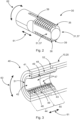
- Fig. 2 shows a male element 30 of the connection assembly 100 of Fig. 1 .
- the male element 30 has a generally bolt-like shape and extends in a longitudinal direction 61.
- the male element 30 comprises two second engaging element portions 36 and two second plain portions 37.
- the second plain portions 37 and the second engaging element portions 36 are arranged around a circumferential direction 62 in an alternating order. Although shown as extending only over a part of the longitudinal direction 61, the second engaging element portions 36 and the second plain portions 37 may also extend over the full length of the male element 30.
- the male element 30 further comprises two first locking grooves 39.
- the second plain portions 37 are designed as flattened sides 31, such as is the case with a flat bolt.
- the second engaging element portions 36 are illustrated as being a plurality of grooves along the longitudinal direction 61.
- the second engaging element portions may be any suitable structure for connecting the second engaging element portions 36 with corresponding first engaging element portions 46 ( Fig. 2 ).
- the second engaging element portions 36 may also be thread-like structures having a pitch, such as with a screw thread.
- the second engaging element portions 36 may also comprise one or more pins, such as with a bayonet locking mechanism.
- the first locking grooves 39 run along the longitudinal direction 61 in the center of each second engaging element portion 36.
- the first locking grooves 39 may be designed to receive a clamp 50 ( Fig. 4 ) to lock circumferential movement of the male element 30 with respect to the female element 40 ( Fig. 3 ), as will be described further below.
- Fig. 3 shows a detailed cut-view of a female element 40 of the connection assembly 100 of Fig. 1 which is mounted inside a first or second tube 10, 20.
- the female element 40 is configured to be connected to the male element 30 of Fig. 2 and comprises a barrel nut 41 and a shock absorbing element 48.
- the shock absorbing element 48 surrounds the barrel nut 41 and connects it to the tube 10, 20.
- the tube 10, 20 comprises a clamp hole 52 for fixing a clamp 50 ( Fig. 4 ), which will be described further below.
- the barrel nut 41 has a generally tubular form and comprises an insert opening 51, which is flush with an opening of the tube 10, 20.
- the barrel nut 41 further comprises two first engaging element portions 46 and two first plain portions 47 (only one shown, Fig. 2 shows a symmetric cut-view of the female element 40) which are arranged around the circumferential direction 62 in an alternating order.
- the barrel nut 40 comprises two second locking grooves 49 which are running along the longitudinal direction 61 inside the first engaging element portions 46.
- the second locking grooves 49 are designed to build a common channel for a clamp 50 ( Fig. 4 ) to lock circumferential movement of the female element 40 with respect to the male element 30 when the female element 40 and the male element 30 are rotated into the locked position.
- the first engaging element portions 46 are designed complementary to the second engaging element portions 36 of the male element of Fig. 2 .
- the first engaging element portions 46 extend along the longitudinal direction 61 over the full length of the barrel nut 41 and comprise a multitude of protrusions, which are designed to engage with the grooves of the second engaging element portions 36 of Fig. 1 .
- the smallest diameter of the barrel nut 41 i.e., the distance between two opposite protrusions of the first engaging element portions 46, is constant over the full length of the barrel nut 41 along the longitudinal direction 61.
- the first plain portions 47 also extend over the full length of the barrel nut 41 along the longitudinal direction 61 and each comprise a conical inner portion 42 and a cylindrical inner portion 43.
- the conical inner portion 42 is arranged immediately at the insert opening 51 in a first longitudinal region 44.
- the cylindrical inner portion 43 is arranged adjacent the conical inner portion 42 in a second longitudinal region 45.
- the cylindrical inner portion 43 has a constant diameter over the full extension of the cylindrical inner portion along the longitudinal direction 61.
- the conical inner portion 42 has a conical shape having a larger diameter at the insert opening 51 than at the transition to the cylindrical inner portion 43.
- the inner diameter of the barrel nut 41 at the cylindrical inner portion 43 is substantially the same as the outer diameter of the second engaging element portions 36 of the male element 30.
- the male element 30 When connecting the male element 30 with the female element 40, the male element 30 is first inserted into the barrel nut 41 such that the second engaging element portions 36 are facing the first plain portions 47.
- the conical shape of the conical inner portion 42 allows the male element 30 to tilt out of the longitudinal direction 61 with respect to the barrel nut 41. Because of the substantially same diameter of the second engaging element 36 and the cylindrical inner portion 43, when the male element 30 is inserted far enough to reach the cylindrical inner portion 43, the male element 30 and the female element 40 are aligned along the longitudinal direction 61.
- the male element 30 may then be connected with the female element 40 by rotating the female element 40 around the longitudinal direction 61 with respect to the male element 30. This brings the first engaging element portions 46 and the second engaging element portions 36 in engagement and locks further longitudinal movement of the male element 30 with respect to the female element 40.
- Aligning the male element 30 and the female element 40 by means of the cylindrical inner portion 43 helps to avoid jamming of the engaging elements 36, 46.
- allowing the male element 30 to tilt out of the longitudinal alignment when the male element 30 is only inserted into the conical inner portion 42 but not into the cylindrical inner portion 43 allows to easily remove and replace a tube 10, 20 from a truss structure 200 ( Fig. 1 ), without having to disassemble the full truss structure 200.
- the shock absorbing element 48 is made from a flexible material, such as a rubber material, that absorbs vibrational loads transmitted between the connection assembly 100 and the tube 10, 20.
- Fig. 4 shows the connection assembly 100 in three different states.
- Fig. 4a shows the connection assembly 100 in an aligned but open state.
- the sequence of connecting the male element 30 with the female element 40 is indicated by the arrows on top of Fig. 4a : first, the tube 10, 20 (together with the female element 40) is rotated by 90 degree around the longitudinal axis 60, such that the second engaging element portions 36 of the male element 30 are facing the first plain portions 47 of the female element 40 ; then, the tube 10, 20 is shifted in the direction of the male element 30 along the longitudinal axis 60 until the male element 30 has been inserted into female element 40 as desired; then, the tube 10, 20 is rotated back into the original position, so that the engaging element portions 36, 46 come into engagement and the first locking groove 39 and the second locking groove 49 are aligned and build a common channel for the clamp 50; finally, the clamp 50 is inserted into the common channel and locked in place with the clamp hole 52, to lock circumferential movement of the female element 40 with respect to the male
- Fig. 4b shows the connection assembly 100 in the assembled state after the procedure described above with regard to Fig. 4a .
- Fig. 4c shows the assembled connection assembly 100 of Fig. 4b in a cut view along the longitudinal axis 60.
- the interlocking of the engaging element portions 36, 46 as well as the arrangement of the clamp 50 within the locking grooves 39, 49 is clearly visible.
- Fig. 5 shows a tube 10, 20 which is mounted between two fixed mounting points (male elements 30 fixed in place, as is shown in Fig. 1 ) during a removal procedure.
- a first step shown in Fig. 5a , the tube 10, 20 is rotated by 90 degrees around the longitudinal axis 60 (or along the circumferential direction 62), in order to unlock the engaging element portions 36, 46. It should be appreciated that the clamp 50 (not shown in Fig. 5 ) has been removed first. After that, the tube 10, 20 is shifted towards one of the male elements 30 (to the left in Fig. 5a ) until the opposite end is free from the other male element 30.
- the tube 10, 20 is simultaneously shifted towards the free male element 30 (to the right side in Fig. 5b ) and tilted out of the longitudinal axis 60.
- This tilting is possible because of the conical inner portion 42, as described above.
- the left male element 30 at some point no more is inside the cylindrical inner portion 43 but only inside the conical inner portion 42, which allows tilting of the tube 10, 20 with regard to the male element 30.
- Reassembling, for example with a new tube 10, 20 may take place in the same way but in the opposite order. This procedure does not need any specialized tooling and can be done in a very time efficient manner.
- the integrated shock absorbing element 48 avoids the need for separate shock absorbing structures.
Landscapes
- Engineering & Computer Science (AREA)
- General Engineering & Computer Science (AREA)
- Mechanical Engineering (AREA)
- Aviation & Aerospace Engineering (AREA)
- Mutual Connection Of Rods And Tubes (AREA)
Claims (12)
- Verbindungsbaugruppe (100) zum Verbinden eines ersten Elements (10) mit einem zweiten Element (20), wobei die Verbindungsbaugruppe (100) Folgendes umfasst:ein männliches Element (30) undein weibliches Element (40),wobei das weibliche Element (40) eine Tonnenmutter (41) umfasst,wobei die Tonnenmutter (41) einen konischen Innenabschnitt (42), der an einem ersten Längsbereich (44) positioniert ist, und einen zylindrischen Innenabschnitt (43), der an einem zweiten Längsbereich (45) positioniert ist, umfasst,wobei die Tonnenmutter (41) mindestens einen ersten Eingriffselementabschnitt (46) und mindestens einen ersten glatten Abschnitt (47) umfasst, die abwechselnd um eine Umfangsrichtung (62) der Tonnenmutter (41) angeordnet sind,wobei das männliche Element (30) eine zylindrische bolzenartige Form aufweist und mindestens einen zweiten Eingriffselementabschnitt (36) und mindestens einen zweiten glatten Abschnitt (37) umfasst, die abwechselnd um eine Umfangsrichtung (62) des männlichen Elements (30) angeordnet sind,wobei das männliche Element (30) ferner abgeflachte Seiten (31) an dem mindestens einen zweiten glatten Abschnitt (37) umfasst undwobei jeder des mindestens einen zweiten Eingriffselementabschnitts (36) des männlichen Elements (30) dazu ausgestaltet ist, mit einem jeweiligen des mindestens einen ersten Eingriffselementabschnitts (46) der Tonnenmutter (41) in Eingriff zu kommen,wobei das weibliche Element (40) ferner ein stoßdämpfendes Element (48) umfasst und wobei das stoßdämpfende Element (48) die Tonnenmutter (41) um ihre äußere Umfangsrichtung umgibt.
- Verbindungsbaugruppe (100) nach Anspruch 1, ferner umfassend eine Klemme (50),wobei das männliche Element (30) ferner eine erste Verriegelungsnut (39) umfasst, die entlang einer Längsrichtung (61) verläuft und in einem der zweiten Eingriffselementabschnitte (36) angeordnet ist,wobei die Tonnenmutter (41) ferner eine zweite Verriegelungsnut (49) umfasst, die entlang einer Längsrichtung (61) der Tonnenmutter (41) verläuft und in einem der ersten Eingriffselementabschnitte (46) angeordnet ist,wobei die Klemme (50) dazu ausgestaltet ist, mit der ersten Verriegelungsnut (39) und der zweiten Verriegelungsnut (49) in Eingriff zu kommen, wenn das männliche Element (30) mit dem weiblichen Element (40) verbunden ist, wodurch eine Drehbewegung des männlichen Elements (30) bezüglich des weiblichen Elements (40) verriegelt wird.
- Verbindungsbaugruppe (100) nach einem der vorhergehenden Ansprüche, wobei ein Innendurchmesser des zylindrischen Innenabschnitts (43) des weiblichen Elements (40) an den ersten glatten Abschnitten (47) die gleiche Größe wie ein Außendurchmesser der zweiten Eingriffselementabschnitte (36) des männlichen Elements (30) aufweist.
- Verbindungsbaugruppe (100) nach einem der vorhergehenden Ansprüche, wobei das weibliche Element (40) eine Einsatzöffnung (51) umfasst,
wobei der konische Innenabschnitt (42) unmittelbar an der Einsatzöffnung (51) angeordnet ist und wobei der zylindrische Innenabschnitt (43) dem konischen Innenabschnitt (42) benachbart und gegenüber der Einsatzöffnung (51) angeordnet ist, so dass der konische Innenabschnitt (42) zwischen der Einsatzöffnung (51) und dem zylindrischen Innenabschnitt (43) angeordnet ist. - Verbindungsbaugruppe (100) nach Anspruch 4, wobei ein Innendurchmesser des konischen Innenabschnitts (42) an der Einsatzöffnung (51) größer als ein Innendurchmesser des konischen Innenabschnitts (42) an dem zylindrischen Innenabschnitt (43) ist, so dass sich der Durchmesser des konischen Innenabschnitts (42) von der Einsatzöffnung (51) in Richtung des zylindrischen Innenabschnitts (43) verjüngt.
- Verbindungsbaugruppe (100) nach Anspruch 4 oder 5, wobei der konische Innenabschnitt (42) direkt in den zylindrischen Innenabschnitt (43) übergeht.
- Verbindungsbaugruppe (100) nach einem der vorhergehenden Ansprüche, wobei jeder des mindestens einen ersten Eingriffselementabschnitts (46) mindestens eine Nut aufweist, wobei die mindestens eine Nut entlang der Umfangsrichtung (62) der Tonnenmutter (41) verläuft und
wobei jeder des mindestens einen zweiten Eingriffselementabschnitts (36) mindestens ein Eingriffselement aufweist, das dazu ausgestaltet ist, mit der mindestens einen Nut des mindestens einen ersten Eingriffselementabschnitts (46) in Eingriff zu kommen. - Verbindungsbaugruppe (100) nach einem der vorhergehenden Ansprüche, wobei jeder des mindestens einen ersten Eingriffselementabschnitts (46) mehrere gewindeähnliche Nuten aufweist.
- Verbindungsbaugruppe (100) nach einem der vorhergehenden Ansprüche, wobei ein sich verjüngender Winkel des konischen Innenabschnitts (42) so bemessen ist, dass er ein Kippen des männlichen Elements (30) bezüglich des weiblichen Elements (40) zwischen 2 Grad und 7 Grad gestattet, wenn das männliche Element (30) in den konischen Innenabschnitt (42) eingesetzt wird.
- Verbindungsbaugruppe (100) nach einem der vorhergehenden Ansprüche, wobei die Tonnenmutter (41) zwei erste Eingriffselementabschnitte (46) umfasst, die um 180 Grad um die Umfangsrichtung der Tonnenmutter (41) voneinander beabstandet sind,wobei das männliche Element (30) zwei zweite Eingriffselementabschnitte (36) umfasst, die um 180 Grad um die Umfangsrichtung des männlichen Elements (30) voneinander beabstandet sind, undwobei das männliche Element (30) und das weibliche Element (40) dazu ausgestaltet sind, durch Einsetzen des männlichen Elements (30) in das weibliche Element (40) und Drehen beider Elemente (30, 40) um 90 Grad um eine gemeinsame Längsachse (60) verbunden zu werden.
- Verbindungsbaugruppe (100) nach einem der vorhergehenden Ansprüche, wobei das stoßdämpfende Element (48) aus einem Gummimaterial hergestellt ist.
- System, umfassend:ein erstes Element (10),ein zweites Element (20),eine erste Verbindungsbaugruppe (100) nach einem der vorhergehenden Ansprüche undeine zweite Verbindungsbaugruppe (100) nach einem der vorhergehenden Ansprüche,wobei das erste Element (10) ein erstes Rohr (10) ist und das zweite Element (20) ein zweites Rohr (20) ist,wobei das weibliche Element (40) der ersten Verbindungsbaugruppe (100) so bemessen ist, dass es mit dem Innendurchmesser des ersten Rohrs (10) übereinstimmt und in einem Endabschnitt des ersten Rohrs (10) angeordnet ist,wobei das weibliche Element (40) der zweiten Verbindungsbaugruppe (100) so bemessen ist, dass es mit dem Innendurchmesser des zweiten Rohrs (10) übereinstimmt und in einem Endabschnitt des zweiten Rohrs (10) angeordnet ist, undwobei die männlichen Elemente (30) der ersten Verbindungsbaugruppe (100) und der zweiten Verbindungsbaugruppe (100) miteinander verbunden sind, so dass sie in einem Winkel zueinander vorragen.
Priority Applications (2)
| Application Number | Priority Date | Filing Date | Title |
|---|---|---|---|
| EP22158606.8A EP4234961B1 (de) | 2022-02-24 | 2022-02-24 | Flexible verbindungsanordnung mit integriertem schwingungsdämpfer |
| US18/172,645 US12504031B2 (en) | 2022-02-24 | 2023-02-22 | Flexible connection assembly with integrated vibration damper |
Applications Claiming Priority (1)
| Application Number | Priority Date | Filing Date | Title |
|---|---|---|---|
| EP22158606.8A EP4234961B1 (de) | 2022-02-24 | 2022-02-24 | Flexible verbindungsanordnung mit integriertem schwingungsdämpfer |
Publications (2)
| Publication Number | Publication Date |
|---|---|
| EP4234961A1 EP4234961A1 (de) | 2023-08-30 |
| EP4234961B1 true EP4234961B1 (de) | 2025-05-21 |
Family
ID=80595489
Family Applications (1)
| Application Number | Title | Priority Date | Filing Date |
|---|---|---|---|
| EP22158606.8A Active EP4234961B1 (de) | 2022-02-24 | 2022-02-24 | Flexible verbindungsanordnung mit integriertem schwingungsdämpfer |
Country Status (2)
| Country | Link |
|---|---|
| US (1) | US12504031B2 (de) |
| EP (1) | EP4234961B1 (de) |
Family Cites Families (32)
| Publication number | Priority date | Publication date | Assignee | Title |
|---|---|---|---|---|
| US752025A (en) * | 1904-02-16 | Nut-lock | ||
| US861139A (en) * | 1907-01-04 | 1907-07-23 | Floyd W Newman | Nut-lock. |
| US1017770A (en) * | 1911-04-13 | 1912-02-20 | John A Latshaw | Nut-lock. |
| US1133860A (en) * | 1913-07-19 | 1915-03-30 | Jacob Herman | Nut and bolt lock. |
| US1105742A (en) * | 1914-03-07 | 1914-08-04 | James W S Barger | Nut-lock. |
| US1299794A (en) * | 1918-03-05 | 1919-04-08 | Fred E Sheldon | Nut-lock. |
| US1369002A (en) * | 1918-04-17 | 1921-02-22 | George Bentz | Nut-lock |
| US1329609A (en) * | 1919-04-02 | 1920-02-03 | Kaddatz Emil | Nut-lock |
| US2730154A (en) * | 1951-07-23 | 1956-01-10 | Northrop Aircraft Inc | Self-locking fastener having longitudinal spring key detent means |
| US2728344A (en) * | 1952-03-15 | 1955-12-27 | Florian F Dauenhauer | Hop vine cutter and picker |
| US2956604A (en) * | 1958-09-30 | 1960-10-18 | John V Crotty | Locking key coupled to lock nut by sliding sleeve |
| DE3148043A1 (de) * | 1981-12-04 | 1983-06-09 | Gernold 4800 Bielefeld Jänisch | "duebel- und bolzenanordnung" |
| JPH0768969B2 (ja) * | 1986-11-19 | 1995-07-26 | 日本ドライブイツト株式会社 | 締結具 |
| US5324297A (en) * | 1989-01-31 | 1994-06-28 | Advanced Osseous Technologies, Inc. | Ultrasonic tool connector |
| US6119306A (en) * | 1998-05-22 | 2000-09-19 | Southco, Inc. | Automotive deck lid bumper |
| US6048151A (en) * | 1999-04-16 | 2000-04-11 | Kwee; Kim | Threaded fastener |
| US7118303B2 (en) * | 2003-12-10 | 2006-10-10 | Zimmer Spine, Inc. | Internally disposed linear fastener system |
| US6817810B2 (en) * | 2002-12-03 | 2004-11-16 | Robert L. Jones | Piering device with adjustable helical plate |
| US7682120B1 (en) * | 2006-09-05 | 2010-03-23 | Harold Goldbaum | Positive locking machine screw mechanism |
| US8382415B1 (en) * | 2006-09-05 | 2013-02-26 | Harold Goldbaum | Rapid-engaging and positive-locking threaded configuration |
| US8142127B1 (en) * | 2008-10-28 | 2012-03-27 | United States Of America As Represented By The Secretary Of The Navy | Torque nut assembly |
| DE102010036482A1 (de) * | 2010-07-19 | 2012-01-19 | Gustav Klauke Gmbh | Mutter und Kombination eines Bolzenteils mit einer Mutter |
| US8992149B2 (en) * | 2011-09-01 | 2015-03-31 | Aerojet Rocketdyne Of De, Inc. | Self retaining anti-rotation key |
| DE102012110986A1 (de) * | 2011-11-22 | 2013-05-23 | Audi Ag | Gewindeanordnung und Verfahren zum Montieren der Gewindeanordnung |
| US9642236B2 (en) * | 2013-09-19 | 2017-05-02 | Hypertherm, Inc. | Thread connection for a torch system |
| US9150145B2 (en) * | 2014-02-07 | 2015-10-06 | Volkswagen Ag | Vehicle headlight assembly with self-adjusting fasteners |
| EP3098463B1 (de) * | 2015-05-26 | 2018-03-14 | Airbus Operations GmbH | Drehgelenk, rahmenkonstruktionskit und verfahren zur herstellung eines drehgelenks |
| EP3135833B1 (de) * | 2015-08-27 | 2019-05-08 | Airbus Operations GmbH | Drehgelenk, rahmenbausatz, rahmenstruktur mit drehgelenken und verfahren zur herstellung eines drehgelenks |
| EP3165450B1 (de) * | 2015-11-05 | 2019-10-16 | Airbus Operations GmbH | Drehverbindung, rahmenkontruktionskit und rahmen |
| EP3254951B1 (de) | 2016-06-06 | 2021-11-03 | Airbus Operations GmbH | Befestigungsanordnung zur befestigung eines ersten objekts an einem zweiten objekt mit variablem abstand |
| EP3480107A1 (de) * | 2017-10-27 | 2019-05-08 | Airbus Operations GmbH | Flugzeugrahmenanordnung, flugzeugstrukturrahmen und flugzeug mit einem flugzeugstrukturrahmen |
| DE102019118494A1 (de) * | 2019-07-09 | 2021-01-14 | Airbus Operations Gmbh | Montagesystem, Verfahren zum Montieren eines Bauteils, Bauteilanordnung und Luftfahrzeug |
-
2022
- 2022-02-24 EP EP22158606.8A patent/EP4234961B1/de active Active
-
2023
- 2023-02-22 US US18/172,645 patent/US12504031B2/en active Active
Also Published As
| Publication number | Publication date |
|---|---|
| US12504031B2 (en) | 2025-12-23 |
| US20230264802A1 (en) | 2023-08-24 |
| EP4234961A1 (de) | 2023-08-30 |
Similar Documents
| Publication | Publication Date | Title |
|---|---|---|
| KR100804000B1 (ko) | 공차 보상 장착 장치 | |
| EP2319437B1 (de) | Mehrachsige Buchse für Sicherungsblech | |
| US7473048B2 (en) | Coupling apparatus for structural members | |
| US6488459B2 (en) | Aerospace fastener | |
| EP3480107A1 (de) | Flugzeugrahmenanordnung, flugzeugstrukturrahmen und flugzeug mit einem flugzeugstrukturrahmen | |
| EP4234961B1 (de) | Flexible verbindungsanordnung mit integriertem schwingungsdämpfer | |
| EP3327213A1 (de) | Knotenelemente, kit und verfahren zum aufbauen | |
| US20160052233A1 (en) | Composite lightweight fitting | |
| AU2018409856A1 (en) | Fastener biasing system | |
| CN113543961B (zh) | 纤维复合支柱 | |
| CA2240542C (en) | Adjustable length brace for cyclic loads | |
| US7419435B2 (en) | Composite torque tube captured end fitting | |
| BR102018071189A2 (pt) | Estrutura tubular compósita, e, métodos de fabricação da estrutura tubular e de melhoria da força compressiva de uma conexão. | |
| JPH0674380A (ja) | 雄形カプラの端金具組立体 | |
| EP2478230B1 (de) | System und verfahren für die starre verbindung von tafeln | |
| KR102142393B1 (ko) | 복합소재 구동축과 플랜지의 접합부 개선 구조 | |
| US10927879B2 (en) | Threaded couplings with locking | |
| US20070217862A1 (en) | Fastening device and method for attaching an object to a support structure | |
| US20200216184A1 (en) | Aircraft engine attachment comprising at least one fork-type system for immobilizing a shear pin in translation, method for mounting said engine attachment and aircraft comprising said engine attachment | |
| RU2038997C1 (ru) | Упругая система вибрационного устройства | |
| US11598356B2 (en) | Fused alignment pin | |
| CN120830671A (zh) | 连接系统 | |
| BR102020006053B1 (pt) | Conjuntos de barra de articulação seguras contra falhas rapidamente ajustáveis especialmente úteis para conectar componentes estruturais de uma aeronave | |
| EP4692581A1 (de) | Kupplungssystem, befestigungsstruktur und fahrzeug | |
| EP4158206B1 (de) | Befestigungselement und fahrzeuganordnung |
Legal Events
| Date | Code | Title | Description |
|---|---|---|---|
| PUAI | Public reference made under article 153(3) epc to a published international application that has entered the european phase |
Free format text: ORIGINAL CODE: 0009012 |
|
| STAA | Information on the status of an ep patent application or granted ep patent |
Free format text: STATUS: THE APPLICATION HAS BEEN PUBLISHED |
|
| AK | Designated contracting states |
Kind code of ref document: A1 Designated state(s): AL AT BE BG CH CY CZ DE DK EE ES FI FR GB GR HR HU IE IS IT LI LT LU LV MC MK MT NL NO PL PT RO RS SE SI SK SM TR |
|
| STAA | Information on the status of an ep patent application or granted ep patent |
Free format text: STATUS: REQUEST FOR EXAMINATION WAS MADE |
|
| 17P | Request for examination filed |
Effective date: 20240226 |
|
| RBV | Designated contracting states (corrected) |
Designated state(s): AL AT BE BG CH CY CZ DE DK EE ES FI FR GB GR HR HU IE IS IT LI LT LU LV MC MK MT NL NO PL PT RO RS SE SI SK SM TR |
|
| GRAP | Despatch of communication of intention to grant a patent |
Free format text: ORIGINAL CODE: EPIDOSNIGR1 |
|
| STAA | Information on the status of an ep patent application or granted ep patent |
Free format text: STATUS: GRANT OF PATENT IS INTENDED |
|
| RIC1 | Information provided on ipc code assigned before grant |
Ipc: F16B 7/18 20060101ALN20250124BHEP Ipc: F16B 7/10 20060101ALN20250124BHEP Ipc: F16B 21/04 20060101ALI20250124BHEP Ipc: F16B 21/02 20060101ALI20250124BHEP Ipc: F16B 37/08 20060101AFI20250124BHEP |
|
| INTG | Intention to grant announced |
Effective date: 20250205 |
|
| GRAS | Grant fee paid |
Free format text: ORIGINAL CODE: EPIDOSNIGR3 |
|
| GRAA | (expected) grant |
Free format text: ORIGINAL CODE: 0009210 |
|
| STAA | Information on the status of an ep patent application or granted ep patent |
Free format text: STATUS: THE PATENT HAS BEEN GRANTED |
|
| AK | Designated contracting states |
Kind code of ref document: B1 Designated state(s): AL AT BE BG CH CY CZ DE DK EE ES FI FR GB GR HR HU IE IS IT LI LT LU LV MC MK MT NL NO PL PT RO RS SE SI SK SM TR |
|
| REG | Reference to a national code |
Ref country code: GB Ref legal event code: FG4D |
|
| REG | Reference to a national code |
Ref country code: CH Ref legal event code: EP |
|
| REG | Reference to a national code |
Ref country code: DE Ref legal event code: R096 Ref document number: 602022014815 Country of ref document: DE |
|
| REG | Reference to a national code |
Ref country code: IE Ref legal event code: FG4D |
|
| REG | Reference to a national code |
Ref country code: NL Ref legal event code: MP Effective date: 20250521 |
|
| PG25 | Lapsed in a contracting state [announced via postgrant information from national office to epo] |
Ref country code: ES Free format text: LAPSE BECAUSE OF FAILURE TO SUBMIT A TRANSLATION OF THE DESCRIPTION OR TO PAY THE FEE WITHIN THE PRESCRIBED TIME-LIMIT Effective date: 20250521 Ref country code: FI Free format text: LAPSE BECAUSE OF FAILURE TO SUBMIT A TRANSLATION OF THE DESCRIPTION OR TO PAY THE FEE WITHIN THE PRESCRIBED TIME-LIMIT Effective date: 20250521 Ref country code: PT Free format text: LAPSE BECAUSE OF FAILURE TO SUBMIT A TRANSLATION OF THE DESCRIPTION OR TO PAY THE FEE WITHIN THE PRESCRIBED TIME-LIMIT Effective date: 20250922 |
|
| REG | Reference to a national code |
Ref country code: LT Ref legal event code: MG9D |
|
| PG25 | Lapsed in a contracting state [announced via postgrant information from national office to epo] |
Ref country code: GR Free format text: LAPSE BECAUSE OF FAILURE TO SUBMIT A TRANSLATION OF THE DESCRIPTION OR TO PAY THE FEE WITHIN THE PRESCRIBED TIME-LIMIT Effective date: 20250822 Ref country code: NO Free format text: LAPSE BECAUSE OF FAILURE TO SUBMIT A TRANSLATION OF THE DESCRIPTION OR TO PAY THE FEE WITHIN THE PRESCRIBED TIME-LIMIT Effective date: 20250821 |
|
| PG25 | Lapsed in a contracting state [announced via postgrant information from national office to epo] |
Ref country code: NL Free format text: LAPSE BECAUSE OF FAILURE TO SUBMIT A TRANSLATION OF THE DESCRIPTION OR TO PAY THE FEE WITHIN THE PRESCRIBED TIME-LIMIT Effective date: 20250521 Ref country code: PL Free format text: LAPSE BECAUSE OF FAILURE TO SUBMIT A TRANSLATION OF THE DESCRIPTION OR TO PAY THE FEE WITHIN THE PRESCRIBED TIME-LIMIT Effective date: 20250521 |
|
| PG25 | Lapsed in a contracting state [announced via postgrant information from national office to epo] |
Ref country code: BG Free format text: LAPSE BECAUSE OF FAILURE TO SUBMIT A TRANSLATION OF THE DESCRIPTION OR TO PAY THE FEE WITHIN THE PRESCRIBED TIME-LIMIT Effective date: 20250521 |
|
| PG25 | Lapsed in a contracting state [announced via postgrant information from national office to epo] |
Ref country code: HR Free format text: LAPSE BECAUSE OF FAILURE TO SUBMIT A TRANSLATION OF THE DESCRIPTION OR TO PAY THE FEE WITHIN THE PRESCRIBED TIME-LIMIT Effective date: 20250521 |
|
| PG25 | Lapsed in a contracting state [announced via postgrant information from national office to epo] |
Ref country code: RS Free format text: LAPSE BECAUSE OF FAILURE TO SUBMIT A TRANSLATION OF THE DESCRIPTION OR TO PAY THE FEE WITHIN THE PRESCRIBED TIME-LIMIT Effective date: 20250821 |
|
| PG25 | Lapsed in a contracting state [announced via postgrant information from national office to epo] |
Ref country code: IS Free format text: LAPSE BECAUSE OF FAILURE TO SUBMIT A TRANSLATION OF THE DESCRIPTION OR TO PAY THE FEE WITHIN THE PRESCRIBED TIME-LIMIT Effective date: 20250921 |
|
| PG25 | Lapsed in a contracting state [announced via postgrant information from national office to epo] |
Ref country code: LV Free format text: LAPSE BECAUSE OF FAILURE TO SUBMIT A TRANSLATION OF THE DESCRIPTION OR TO PAY THE FEE WITHIN THE PRESCRIBED TIME-LIMIT Effective date: 20250521 |
|
| REG | Reference to a national code |
Ref country code: AT Ref legal event code: MK05 Ref document number: 1796967 Country of ref document: AT Kind code of ref document: T Effective date: 20250521 |
|
| PG25 | Lapsed in a contracting state [announced via postgrant information from national office to epo] |
Ref country code: SM Free format text: LAPSE BECAUSE OF FAILURE TO SUBMIT A TRANSLATION OF THE DESCRIPTION OR TO PAY THE FEE WITHIN THE PRESCRIBED TIME-LIMIT Effective date: 20250521 Ref country code: DK Free format text: LAPSE BECAUSE OF FAILURE TO SUBMIT A TRANSLATION OF THE DESCRIPTION OR TO PAY THE FEE WITHIN THE PRESCRIBED TIME-LIMIT Effective date: 20250521 Ref country code: AT Free format text: LAPSE BECAUSE OF FAILURE TO SUBMIT A TRANSLATION OF THE DESCRIPTION OR TO PAY THE FEE WITHIN THE PRESCRIBED TIME-LIMIT Effective date: 20250521 |
|
| PG25 | Lapsed in a contracting state [announced via postgrant information from national office to epo] |
Ref country code: CZ Free format text: LAPSE BECAUSE OF FAILURE TO SUBMIT A TRANSLATION OF THE DESCRIPTION OR TO PAY THE FEE WITHIN THE PRESCRIBED TIME-LIMIT Effective date: 20250521 |
|
| PG25 | Lapsed in a contracting state [announced via postgrant information from national office to epo] |
Ref country code: EE Free format text: LAPSE BECAUSE OF FAILURE TO SUBMIT A TRANSLATION OF THE DESCRIPTION OR TO PAY THE FEE WITHIN THE PRESCRIBED TIME-LIMIT Effective date: 20250521 |
|
| PG25 | Lapsed in a contracting state [announced via postgrant information from national office to epo] |
Ref country code: SK Free format text: LAPSE BECAUSE OF FAILURE TO SUBMIT A TRANSLATION OF THE DESCRIPTION OR TO PAY THE FEE WITHIN THE PRESCRIBED TIME-LIMIT Effective date: 20250521 |
|
| PG25 | Lapsed in a contracting state [announced via postgrant information from national office to epo] |
Ref country code: IT Free format text: LAPSE BECAUSE OF FAILURE TO SUBMIT A TRANSLATION OF THE DESCRIPTION OR TO PAY THE FEE WITHIN THE PRESCRIBED TIME-LIMIT Effective date: 20250521 |
|
| REG | Reference to a national code |
Ref country code: DE Ref legal event code: R097 Ref document number: 602022014815 Country of ref document: DE |
|
| PLBE | No opposition filed within time limit |
Free format text: ORIGINAL CODE: 0009261 |
|
| STAA | Information on the status of an ep patent application or granted ep patent |
Free format text: STATUS: NO OPPOSITION FILED WITHIN TIME LIMIT |
|
| REG | Reference to a national code |
Ref country code: CH Ref legal event code: L10 Free format text: ST27 STATUS EVENT CODE: U-0-0-L10-L00 (AS PROVIDED BY THE NATIONAL OFFICE) Effective date: 20260402 |
|
| PGFP | Annual fee paid to national office [announced via postgrant information from national office to epo] |
Ref country code: GB Payment date: 20260220 Year of fee payment: 5 |
|
| PGFP | Annual fee paid to national office [announced via postgrant information from national office to epo] |
Ref country code: DE Payment date: 20260218 Year of fee payment: 5 |
|
| PGFP | Annual fee paid to national office [announced via postgrant information from national office to epo] |
Ref country code: FR Payment date: 20260219 Year of fee payment: 5 |
|
| 26N | No opposition filed |
Effective date: 20260224 |