EP4234979A2 - Säge mit hin und her gehendem sägeblatt - Google Patents
Säge mit hin und her gehendem sägeblatt Download PDFInfo
- Publication number
- EP4234979A2 EP4234979A2 EP23175134.8A EP23175134A EP4234979A2 EP 4234979 A2 EP4234979 A2 EP 4234979A2 EP 23175134 A EP23175134 A EP 23175134A EP 4234979 A2 EP4234979 A2 EP 4234979A2
- Authority
- EP
- European Patent Office
- Prior art keywords
- axis
- power tool
- spindle
- longitudinal
- yoke
- Prior art date
- Legal status (The legal status is an assumption and is not a legal conclusion. Google has not performed a legal analysis and makes no representation as to the accuracy of the status listed.)
- Pending
Links
Images


Classifications
-
- B—PERFORMING OPERATIONS; TRANSPORTING
- B23—MACHINE TOOLS; METAL-WORKING NOT OTHERWISE PROVIDED FOR
- B23D—PLANING; SLOTTING; SHEARING; BROACHING; SAWING; FILING; SCRAPING; LIKE OPERATIONS FOR WORKING METAL BY REMOVING MATERIAL, NOT OTHERWISE PROVIDED FOR
- B23D51/00—Sawing machines or sawing devices working with straight blades, characterised only by constructional features of particular parts; Carrying or attaching means for tools, covered by this subclass, which are connected to a carrier at both ends
- B23D51/16—Sawing machines or sawing devices working with straight blades, characterised only by constructional features of particular parts; Carrying or attaching means for tools, covered by this subclass, which are connected to a carrier at both ends of drives or feed mechanisms for straight tools, e.g. saw blades, or bows
- B23D51/161—Sawing machines or sawing devices working with straight blades, characterised only by constructional features of particular parts; Carrying or attaching means for tools, covered by this subclass, which are connected to a carrier at both ends of drives or feed mechanisms for straight tools, e.g. saw blades, or bows with dynamic balancing
-
- B—PERFORMING OPERATIONS; TRANSPORTING
- B23—MACHINE TOOLS; METAL-WORKING NOT OTHERWISE PROVIDED FOR
- B23D—PLANING; SLOTTING; SHEARING; BROACHING; SAWING; FILING; SCRAPING; LIKE OPERATIONS FOR WORKING METAL BY REMOVING MATERIAL, NOT OTHERWISE PROVIDED FOR
- B23D49/00—Machines or devices for sawing with straight reciprocating saw blades, e.g. hacksaws
- B23D49/10—Hand-held or hand-operated sawing devices with straight saw blades
- B23D49/16—Hand-held or hand-operated sawing devices with straight saw blades actuated by electric or magnetic power or prime movers
-
- B—PERFORMING OPERATIONS; TRANSPORTING
- B23—MACHINE TOOLS; METAL-WORKING NOT OTHERWISE PROVIDED FOR
- B23D—PLANING; SLOTTING; SHEARING; BROACHING; SAWING; FILING; SCRAPING; LIKE OPERATIONS FOR WORKING METAL BY REMOVING MATERIAL, NOT OTHERWISE PROVIDED FOR
- B23D51/00—Sawing machines or sawing devices working with straight blades, characterised only by constructional features of particular parts; Carrying or attaching means for tools, covered by this subclass, which are connected to a carrier at both ends
- B23D51/01—Sawing machines or sawing devices working with straight blades, characterised only by constructional features of particular parts; Carrying or attaching means for tools, covered by this subclass, which are connected to a carrier at both ends characterised by the handle
-
- B—PERFORMING OPERATIONS; TRANSPORTING
- B23—MACHINE TOOLS; METAL-WORKING NOT OTHERWISE PROVIDED FOR
- B23D—PLANING; SLOTTING; SHEARING; BROACHING; SAWING; FILING; SCRAPING; LIKE OPERATIONS FOR WORKING METAL BY REMOVING MATERIAL, NOT OTHERWISE PROVIDED FOR
- B23D51/00—Sawing machines or sawing devices working with straight blades, characterised only by constructional features of particular parts; Carrying or attaching means for tools, covered by this subclass, which are connected to a carrier at both ends
- B23D51/08—Sawing machines or sawing devices working with straight blades, characterised only by constructional features of particular parts; Carrying or attaching means for tools, covered by this subclass, which are connected to a carrier at both ends of devices for mounting straight saw blades or other tools
- B23D51/10—Sawing machines or sawing devices working with straight blades, characterised only by constructional features of particular parts; Carrying or attaching means for tools, covered by this subclass, which are connected to a carrier at both ends of devices for mounting straight saw blades or other tools for hand-held or hand-operated devices
-
- B—PERFORMING OPERATIONS; TRANSPORTING
- B25—HAND TOOLS; PORTABLE POWER-DRIVEN TOOLS; MANIPULATORS
- B25F—COMBINATION OR MULTI-PURPOSE TOOLS NOT OTHERWISE PROVIDED FOR; DETAILS OR COMPONENTS OF PORTABLE POWER-DRIVEN TOOLS NOT PARTICULARLY RELATED TO THE OPERATIONS PERFORMED AND NOT OTHERWISE PROVIDED FOR
- B25F5/00—Details or components of portable power-driven tools not particularly related to the operations performed and not otherwise provided for
- B25F5/02—Construction of casings, bodies or handles
-
- F—MECHANICAL ENGINEERING; LIGHTING; HEATING; WEAPONS; BLASTING
- F16—ENGINEERING ELEMENTS AND UNITS; GENERAL MEASURES FOR PRODUCING AND MAINTAINING EFFECTIVE FUNCTIONING OF MACHINES OR INSTALLATIONS; THERMAL INSULATION IN GENERAL
- F16H—GEARING
- F16H21/00—Gearings comprising primarily only links or levers, with or without slides
- F16H21/10—Gearings comprising primarily only links or levers, with or without slides all movement being in, or parallel to, a single plane
- F16H21/16—Gearings comprising primarily only links or levers, with or without slides all movement being in, or parallel to, a single plane for interconverting rotary motion and reciprocating motion
- F16H21/18—Crank gearings; Eccentric gearings
- F16H21/36—Crank gearings; Eccentric gearings without swinging connecting-rod, e.g. with epicyclic parallel motion, slot-and-crank motion
-
- F—MECHANICAL ENGINEERING; LIGHTING; HEATING; WEAPONS; BLASTING
- F16—ENGINEERING ELEMENTS AND UNITS; GENERAL MEASURES FOR PRODUCING AND MAINTAINING EFFECTIVE FUNCTIONING OF MACHINES OR INSTALLATIONS; THERMAL INSULATION IN GENERAL
- F16H—GEARING
- F16H1/00—Toothed gearings for conveying rotary motion
- F16H1/02—Toothed gearings for conveying rotary motion without gears having orbital motion
- F16H1/04—Toothed gearings for conveying rotary motion without gears having orbital motion involving only two intermeshing members
- F16H1/12—Toothed gearings for conveying rotary motion without gears having orbital motion involving only two intermeshing members with non-parallel axes
- F16H1/14—Toothed gearings for conveying rotary motion without gears having orbital motion involving only two intermeshing members with non-parallel axes comprising conical gears only
Definitions
- the present application relates to a power tool.
- the present application relates to a reciprocating saw.
- Reciprocating saws are used to cut a variety of objects made from a variety of materials, such as metal pipes, wood and dry wall.
- a cordless, compact reciprocating saw allows for cutting operations in tight spaces or awkward angles for plumbing, electrical, remodeling and HVAC applications.
- the invention provides a power tool including a housing having a handle configured to be grasped by a user, a motor supported by the housing, a driving gear rotated by the motor, and a driven gear engaging the driving gear to be rotated by the driving gear about a rotation axis.
- the power tool also includes a pin extending from the driven gear and offset from the rotation axis and a spindle having a yoke coupled to the pin to translate rotation of the driven gear into reciprocating motion of the spindle.
- a notch is formed in an outer periphery of the yoke to provide clearance for the driving gear as the spindle is driven by the pin.
- the invention provides a power tool including a housing having a handle configured to be grasped by a user, a motor supported by the housing, a driving gear rotated by the motor, and a driven gear engaging the driving gear to be rotated by the driving gear about a rotation axis.
- the power tool also includes a pin extending from the driven gear and offset from the rotation axis and a spindle having a yoke coupled to the pin to translate rotation of the driven gear into reciprocating motion of the spindle.
- the spindle defines a spindle axis, and the yoke includes a notch that is offset from the spindle axis. The notch provides clearance for the driving gear as the spindle is driven by the pin.
- the invention provides a housing having a handle configured to be grasped by a user, a motor supported by the housing, a driving gear rotated by the motor, a first driven gear engaging the driving gear to be rotated by the driving gear about a rotation axis and a second driven gear facing the first driven gear and engaging the driving gear to be rotated by the driving gear about the rotation axis.
- the second driven gear defines a channel.
- the power tool also includes a pin extending from the first driven gear and offset from the rotation axis. The pin has an end received in the channel of the second driven gear.
- the power tool also includes a spindle having a yoke coupled to the pin to translate rotation of the first and second driven gears into reciprocating motion of the spindle.
- FIGS. 1-3B A portable power tool 10 is shown in FIGS. 1-3B .
- the power tool 10 is a reciprocating saw.
- the saw 10 is powered by a power tool battery pack 14.
- the battery pack 14 may be configured to connect and power a variety of tools in addition to the reciprocating saw 10.
- the saw 10 may be a corded power tool.
- the power tool may be another hand-held power tool, such as, for example, another type of power tool that translates rotary motion into reciprocating motion.
- the saw 10 includes a housing 40. As shown in FIG. 1 , the housing 40 has a first housing portion 44 and a second housing portion 48. Each housing portion 44, 48 is formed of plastic; however, in some embodiments, the housing portions 44, 48 may be formed of other materials.
- the housing 40 defines a handle 50, a motor housing portion 56, and a gear case housing portion 60.
- the handle 50 includes at least one grip surface configured to be grasped by a user.
- the handle 50 can also define a battery receiving portion 64 ( FIGS. 3A and 3B ) for receiving the battery pack 14. In other embodiments, the battery receiving portion 64 may be defined elsewhere within the housing 40.
- the motor housing portion 56 supports a motor 68 ( FIGS. 3A and 3B ), and the gear case housing portion 60 in turn supports a gear case ( FIGS. 2 and 3 ).
- the gear case includes first and second gear case portions 76, only one of which is shown in FIGS. 3A and 3B .
- the battery receiving portion 64 is configured as a cavity.
- the battery pack 14 FIG. 1
- the pack 14 is inserted into the cavity and substantially closes the cavity.
- an actuator 90 is positioned on the handle 50 for powering the saw 10.
- the actuator 90 is electrically coupled to the battery pack 14 and the motor 68 to selectively energize the motor 68 when actuated.
- the actuator 90 is an on/off trigger.
- the switch 90 may be a variable speed trigger, a two speed trigger, a push button or another suitable actuator.
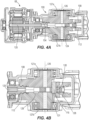
- the first and second gear case portions 76 enclose a drive system 100 for the saw 10.
- the drive system 100 is a scotch yoke mechanism.
- the drive system 100 includes a driving gear 104, a first driven gear 108, a second driven gear 112, a pin 116, a bushing 120, and a spindle 124.
- the driving gear 104 is coupled to an output shaft 125 of the motor 68 for rotation with the output shaft 125.
- the illustrated driving gear 104 is an output spindle having a tapered or frustoconically-shaped outer surface. More particularly, the illustrated driving gear 104 is a spiral bevel pinion.
- first and second driven gears 108, 112 are positioned on opposing sides of the driving gear 104.
- the first and second driven gears 108, 112 both engage the driving gear 104 to be rotated about a rotation axis 126.
- Each driven gear 108, 112 is supported by a bearing 127a, 127b for rotation relative to the housing 40.
- the bearings 127a, 127b may be press-fit or otherwise secured within recesses formed in the housing portions 44, 48.
- the illustrated first driven gear 108 is a first bevel gear
- the second driven gear 112 is a second bevel gear.
- first and second driven gears 108, 112 are spiral bevel gears.
- Each driven gear 108, 112 includes a relatively thick portion 129 and a relatively thin portion 130 that function as counterbalance weights during rotation of the gears 108, 112.
- the pin 116 extends from the first driven gear 108 toward the second driven gear 112.
- the pin 116 is offset from the rotation axis 126 of the driven gears 108, 112.
- the pin 116 is a separate element that is secured (e.g., press-fit, etc.) to the first driven gear 108 for movement about the rotation axis 126.
- the pin 116 may be integrally formed as a single component with the first driven gear 108.
- the illustrated pin 116 is received by the bushing 120 and includes an end 131 that extends beyond the bushing 120.
- the end 131 of the pin 116 is received in a channel 128 ( FIGS. 4B ) of the second driven gear 112.
- the illustrated channel 128 is a recessed track formed in a face 133 of the second driven gear 112 that faces the first driven gear 108.
- the recessed track is formed as a continuous circle or annulus in the face 133.
- the spindle 124 includes a yoke 180, a spindle shaft 184, and a blade clamp (not shown).
- the blade clamp is opposite the yoke 180.
- the yoke 180 is integrally formed as a single piece with the spindle 124 such that the yoke 180 is part of the spindle 124.
- the yoke 180 may be a separate piece that is secured to the spindle 124.
- a tool element 192 such as a saw blade, is coupled to the spindle shaft 184 via the blade clamp.
- the blade clamp may include the blade clamp assembly shown and described in U.S. Patent No.
- the blade clamp can also be configured to accept a variety of reciprocating saw blades, jig saw blades, and/or hack saw blades.
- the yoke 180 includes a body 132 with an aperture 136 extending therethrough.
- the body 132 also has a notch 140 formed in an outer periphery of the yoke 180.
- the notch 140 is formed at an upper peripheral corner of the yoke 180 nearest the driving gear 104.
- the notch 140 removes material from the yoke 180 to provide clearance as the yoke 180 moves within the gear case. More particularly, the notch 140 allows the yoke 180 to translate rotation of the driven gears 108, 112 into reciprocating motion without having the yoke 180 contact the driving gear 104.
- the aperture 136 receives the pin 116 and the bushing 120 ( FIGS. 3A and 3B ).
- the aperture 136 is an elongated oval-shape. More specifically, the aperture 136 defines a first length 144 between arcuate sides 148, 152 and a second length 156 between substantially parallel sides 160, 164.
- the second length 156 is generally equal to the outer diameter of the bushing 120 so that the bushing 120 pushes (e.g., reciprocates) the yoke 180 forward and backward as the driven gears 108, 112 are rotated.
- the first length 144 is longer than the second length 156 and provides clearance for the pin 116 and the bushing 120 to move laterally within the aperture 136.
- the aperture 136 defines a longitudinal axis 172 extending along the first length 144.
- the notch 140 is formed along an axis 168 in the outer perimeter of the yoke 180.
- the axis 168 is obliquely angled relative to the longitudinal axis 172 of the aperture 136.
- the axis 168 of the notch 140 may be oriented at an angle ⁇ between 45° and 75° relative to the longitudinal axis 172. In the illustrated embodiment, the angle ⁇ is about 60°.
- the spindle 124 and the saw blade 192 are positioned along a longitudinal spindle axis 196 defined along a length of the spindle 124.
- the spindle 124 translates back and forth (e.g., reciprocates) along the longitudinal axis 196.
- the notch 140 is offset from the longitudinal axis 196 of the spindle 124.
- the notch 140 is formed in a corner of the yoke 180 so the yoke 180 is nonsymmetrical about both the longitudinal aperture axis 172 and the longitudinal spindle axis 196. As shown in FIGS.
- the output shaft 125 of the motor 68 is oriented at an oblique angle relative to the longitudinal spindle axis 196 so the driving gear 104 is positioned adjacent (i.e., nearest to) the corner of the yoke 180 with the notch 140.
- the axis 168 of the notch 140 is obliquely angled relative to the longitudinal axis 196 of the spindle 124.
- the axis 168 of the notch 140 may be oriented at an angle ⁇ between 15° and 45° relative to the longitudinal axis 196. In the illustrated embodiment, the angle ⁇ is about 30°.
- the driving gear 104 is coupled to the output shaft 125 of the motor 68.
- the pinion 104 rotates and engages teeth of the driven gears 108, 112 to rotate the gears 108, 112.
- the driven gears 108, 112 counterbalance each other as well as the spindle 124 to counterbalance the forces from the reciprocating motion of the spindle 124.
- the pin 116 is offset from the axis of rotation 126 of the driven gears 108, 112, the pin 116 moves around the axis of rotation 126 as the driven gears 108, 112 rotate.
- the pin 116 also moves within the aperture 136 of the yoke 180 to reciprocate the yoke 180 and the spindle 124.
- the notch 140 provides clearance for the pinion 104 during reciprocating motion to allow for an increased reciprocating stroke length.
- the bushing 120 moves up and down along the pin 116.
- the bushing 120 can move up and down between the first and the second driven gears 108, 112 and remain in contact with the pin 116. This arrangement helps reduce uneven wearing of the inner surface of the bushing 120.
- the saw 10 further includes multiple modes that allow the user to change the output reciprocating speed of the tool element 192.
- the modes may allow the change in reciprocating speed by adjusting the motor speed or by adjusting the physical gearing.
- the user may change between the modes via an actuator on the housing, a remote device, or an application on a smart phone or tablet computer.
- the saw 10 also includes a shoe assembly 200.
- the shoe assembly 200 is coupled to a front end of the housing 40 opposite from the battery pack 14.
- the shoe assembly 200 is a movable (i.e., pivotable) shoe assembly.
- the shoe assembly 200 includes a front surface or plate 204 which engages or rests on a workpiece.
- the front plate 204 also defines an opening 208 for the tool element 192 to pass through.
- the front plate 204 is movably or pivotably coupled to two connecting members 212, which connect the shoe assembly 200 to the housing 40.
- the front plate 204 is pivotable about an axis 220.
- the shoe assembly 200 may be an otherwise adjustable shoe assembly or a fixed show assembly.
Landscapes
- Engineering & Computer Science (AREA)
- Mechanical Engineering (AREA)
- General Engineering & Computer Science (AREA)
- Sawing (AREA)
- Connection Of Motors, Electrical Generators, Mechanical Devices, And The Like (AREA)
Applications Claiming Priority (3)
| Application Number | Priority Date | Filing Date | Title |
|---|---|---|---|
| US201762445291P | 2017-01-12 | 2017-01-12 | |
| EP18739420.0A EP3568253B1 (de) | 2017-01-12 | 2018-01-12 | Säge mit hin und her gehendem sägeblatt |
| PCT/US2018/013438 WO2018132631A1 (en) | 2017-01-12 | 2018-01-12 | Reciprocating saw |
Related Parent Applications (1)
| Application Number | Title | Priority Date | Filing Date |
|---|---|---|---|
| EP18739420.0A Division EP3568253B1 (de) | 2017-01-12 | 2018-01-12 | Säge mit hin und her gehendem sägeblatt |
Publications (2)
| Publication Number | Publication Date |
|---|---|
| EP4234979A2 true EP4234979A2 (de) | 2023-08-30 |
| EP4234979A3 EP4234979A3 (de) | 2023-10-18 |
Family
ID=62782509
Family Applications (2)
| Application Number | Title | Priority Date | Filing Date |
|---|---|---|---|
| EP23175134.8A Pending EP4234979A3 (de) | 2017-01-12 | 2018-01-12 | Säge mit hin und her gehendem sägeblatt |
| EP18739420.0A Active EP3568253B1 (de) | 2017-01-12 | 2018-01-12 | Säge mit hin und her gehendem sägeblatt |
Family Applications After (1)
| Application Number | Title | Priority Date | Filing Date |
|---|---|---|---|
| EP18739420.0A Active EP3568253B1 (de) | 2017-01-12 | 2018-01-12 | Säge mit hin und her gehendem sägeblatt |
Country Status (4)
| Country | Link |
|---|---|
| US (2) | US10603728B2 (de) |
| EP (2) | EP4234979A3 (de) |
| CN (1) | CN211889238U (de) |
| WO (1) | WO2018132631A1 (de) |
Families Citing this family (20)
| Publication number | Priority date | Publication date | Assignee | Title |
|---|---|---|---|---|
| US20180264566A1 (en) * | 2017-03-20 | 2018-09-20 | Milwaukee Electric Tool Corporation | Reciprocating saw |
| CN110709202B (zh) * | 2017-05-31 | 2022-03-01 | 工机控股株式会社 | 往复运动工具 |
| USD928578S1 (en) * | 2019-05-09 | 2021-08-24 | Shenzhen Allsight E-business Co., Ltd. | Reciprocating saw |
| WO2021041805A1 (en) * | 2019-08-29 | 2021-03-04 | Milwaukee Electric Tool Corporation | Reciprocating saw |
| DE102019215023A1 (de) * | 2019-09-30 | 2021-04-01 | Robert Bosch Gmbh | Luftkompressionsvorrichtung |
| USD934042S1 (en) * | 2019-10-09 | 2021-10-26 | Würth International Ag | Caulking gun |
| CN113145933A (zh) * | 2021-04-27 | 2021-07-23 | 宁波南浦机电有限公司 | 一种多功能往复切割工具 |
| USD959945S1 (en) * | 2021-06-22 | 2022-08-09 | Jimin Lin | Mini chainsaw |
| USD957225S1 (en) * | 2021-07-04 | 2022-07-12 | Hefei Qiongzhi Network Technology Co., Ltd. | Mini chainsaw |
| USD1041279S1 (en) * | 2021-09-02 | 2024-09-10 | Techtronic Cordless Gp | Pruner saw |
| JP2023040861A (ja) * | 2021-09-10 | 2023-03-23 | 株式会社マキタ | 往復動切断工具 |
| CN116944586A (zh) | 2022-04-12 | 2023-10-27 | 创科无线普通合伙 | 手持式电动工具 |
| US12564890B2 (en) | 2022-05-04 | 2026-03-03 | Milwaukee Electric Tool Corporation | Jigsaw |
| JP1735659S (ja) * | 2022-07-06 | 2023-01-30 | 携帯用電気チェンソー本体 | |
| USD1049811S1 (en) * | 2022-09-30 | 2024-11-05 | Greenworks (Jiangsu) Co., Ltd | Chain saw |
| US12519372B2 (en) * | 2022-09-30 | 2026-01-06 | Milwaukee Electric Tool Corporation | Pass-through brushless motor |
| US12599978B2 (en) | 2023-03-01 | 2026-04-14 | Milwaukee Electric Tool Corporation | Reciprocating tool |
| USD1074368S1 (en) * | 2023-10-19 | 2025-05-13 | Minli Liao | Chainsaw |
| US12466048B2 (en) * | 2023-12-27 | 2025-11-11 | Black & Decker Inc. | Reciprocating tool having offset spur gear and counterweighting assembly |
| USD1081312S1 (en) * | 2024-02-29 | 2025-07-01 | Andreas Stihl Ag & Co. Kg | Chainsaw |
Citations (1)
| Publication number | Priority date | Publication date | Assignee | Title |
|---|---|---|---|---|
| US6725548B1 (en) | 1996-03-01 | 2004-04-27 | Milwaukee Electric Tool Corporation | Keyless blade clamp mechanism |
Family Cites Families (18)
| Publication number | Priority date | Publication date | Assignee | Title |
|---|---|---|---|---|
| US2713271A (en) * | 1951-07-17 | 1955-07-19 | Mall Tool Company | Motion converting means |
| DE2925401C2 (de) * | 1979-06-23 | 1983-12-22 | Siegfried 7971 Aichstetten Gebhart | Stichsäge mit Motorantrieb |
| US4628605A (en) * | 1985-06-10 | 1986-12-16 | Porter-Cable Corporation | Orbital bayonet saw |
| US5132653A (en) * | 1987-09-09 | 1992-07-21 | Yoshiteru Nakatake | Electromagnetic switch |
| JPH0533223Y2 (de) | 1987-10-08 | 1993-08-24 | ||
| US5755293A (en) * | 1995-03-31 | 1998-05-26 | Bourke; George C. | Drill/saw apparatus |
| US5946764A (en) * | 1997-06-05 | 1999-09-07 | Tworzydlo; Wlodzimierz Woytek | Wiper with tiliable substructure and airflow deflectors |
| US6881151B1 (en) * | 2001-11-27 | 2005-04-19 | Carl Jantz | Universal joint |
| US20030145472A1 (en) * | 2002-02-01 | 2003-08-07 | Swift Edgar Leon | Reciprocating saw with flush cutting capability |
| DE102006031513A1 (de) | 2006-07-07 | 2008-01-17 | Robert Bosch Gmbh | Handwerkzeugmaschine, insbesondere Handsäge |
| GB2469785B (en) | 2008-03-07 | 2012-12-19 | Milwaukee Electric Tool Corp | Reciprocating saw |
| US8407902B2 (en) * | 2008-03-07 | 2013-04-02 | Milwaukee Electric Tool Corporation | Reciprocating power tool having a counterbalance device |
| DE102010038343A1 (de) | 2009-07-23 | 2011-02-24 | Milwaukee Electric Tool Corp., Brookfield | Säbelsäge |
| US8636081B2 (en) | 2011-12-15 | 2014-01-28 | Milwaukee Electric Tool Corporation | Rotary hammer |
| US9221112B2 (en) | 2010-03-10 | 2015-12-29 | Milwaukee Electric Tool Corporation | Motor mount for a power tool |
| US10413980B2 (en) | 2011-04-01 | 2019-09-17 | Milwaukee Electric Tool Corporation | Reciprocating saw, such as a jigsaw |
| US9073563B2 (en) * | 2011-05-18 | 2015-07-07 | Crystal Glass Canada Ltd. | Reciprocating power tool |
| US20130133210A1 (en) | 2011-11-30 | 2013-05-30 | Robert Bosch Gmbh | Articulating Jig Saw |
-
2018
- 2018-01-12 CN CN201890000441.3U patent/CN211889238U/zh not_active Expired - Fee Related
- 2018-01-12 EP EP23175134.8A patent/EP4234979A3/de active Pending
- 2018-01-12 EP EP18739420.0A patent/EP3568253B1/de active Active
- 2018-01-12 US US15/869,203 patent/US10603728B2/en active Active
- 2018-01-12 WO PCT/US2018/013438 patent/WO2018132631A1/en not_active Ceased
-
2020
- 2020-02-19 US US16/794,385 patent/US10960475B2/en active Active
Patent Citations (1)
| Publication number | Priority date | Publication date | Assignee | Title |
|---|---|---|---|---|
| US6725548B1 (en) | 1996-03-01 | 2004-04-27 | Milwaukee Electric Tool Corporation | Keyless blade clamp mechanism |
Also Published As
| Publication number | Publication date |
|---|---|
| EP4234979A3 (de) | 2023-10-18 |
| WO2018132631A1 (en) | 2018-07-19 |
| US10960475B2 (en) | 2021-03-30 |
| US20180193932A1 (en) | 2018-07-12 |
| US10603728B2 (en) | 2020-03-31 |
| EP3568253A4 (de) | 2020-10-28 |
| US20200180051A1 (en) | 2020-06-11 |
| EP3568253B1 (de) | 2023-05-31 |
| CN211889238U (zh) | 2020-11-10 |
| EP3568253A1 (de) | 2019-11-20 |
Similar Documents
| Publication | Publication Date | Title |
|---|---|---|
| US10960475B2 (en) | Reciprocating saw | |
| US11919097B2 (en) | Reciprocating saw | |
| US20180264566A1 (en) | Reciprocating saw | |
| US9061411B2 (en) | Reciprocating power tool having a counterbalance device | |
| US8789283B2 (en) | Reciprocating saw | |
| US9233427B2 (en) | Portable battery-powered reciprocating saw | |
| US9956625B2 (en) | Reciprocating saw | |
| US12377479B2 (en) | Reciprocating saw | |
| US11052476B2 (en) | Reciprocating saw | |
| US11820038B2 (en) | Handheld punch tool | |
| US11311952B2 (en) | Reciprocating saw | |
| US10272506B2 (en) | Reciprocating tool with linear guides | |
| EP3568265B1 (de) | Oszillierendes werkzeug mit mehreren oszillierenden winkeln | |
| KR20150008602A (ko) | 휴대용 절단장치 | |
| CN212793365U (zh) | 一种便携式刀锯 |
Legal Events
| Date | Code | Title | Description |
|---|---|---|---|
| PUAI | Public reference made under article 153(3) epc to a published international application that has entered the european phase |
Free format text: ORIGINAL CODE: 0009012 |
|
| STAA | Information on the status of an ep patent application or granted ep patent |
Free format text: STATUS: THE APPLICATION HAS BEEN PUBLISHED |
|
| AC | Divisional application: reference to earlier application |
Ref document number: 3568253 Country of ref document: EP Kind code of ref document: P |
|
| AK | Designated contracting states |
Kind code of ref document: A2 Designated state(s): AL AT BE BG CH CY CZ DE DK EE ES FI FR GB GR HR HU IE IS IT LI LT LU LV MC MK MT NL NO PL PT RO RS SE SI SK SM TR |
|
| REG | Reference to a national code |
Ref country code: DE Ref legal event code: R079 Free format text: PREVIOUS MAIN CLASS: F16H0021360000 Ipc: B23D0049160000 |
|
| PUAL | Search report despatched |
Free format text: ORIGINAL CODE: 0009013 |
|
| RIN1 | Information on inventor provided before grant (corrected) |
Inventor name: GALL, SIMON M. |
|
| AK | Designated contracting states |
Kind code of ref document: A3 Designated state(s): AL AT BE BG CH CY CZ DE DK EE ES FI FR GB GR HR HU IE IS IT LI LT LU LV MC MK MT NL NO PL PT RO RS SE SI SK SM TR |
|
| RIC1 | Information provided on ipc code assigned before grant |
Ipc: F16H 21/36 20060101ALI20230912BHEP Ipc: F16H 1/14 20060101ALI20230912BHEP Ipc: B25F 5/02 20060101ALI20230912BHEP Ipc: B23D 51/16 20060101ALI20230912BHEP Ipc: B23D 49/16 20060101AFI20230912BHEP |
|
| STAA | Information on the status of an ep patent application or granted ep patent |
Free format text: STATUS: REQUEST FOR EXAMINATION WAS MADE |
|
| 17P | Request for examination filed |
Effective date: 20240313 |
|
| RBV | Designated contracting states (corrected) |
Designated state(s): AL AT BE BG CH CY CZ DE DK EE ES FI FR GB GR HR HU IE IS IT LI LT LU LV MC MK MT NL NO PL PT RO RS SE SI SK SM TR |