EP4235012A1 - Tank mit innen- und aussenräumen sowie mindestens einem verbindungssystem mit flexiblen radialen lamellen zur verbindung dieser behälter - Google Patents
Tank mit innen- und aussenräumen sowie mindestens einem verbindungssystem mit flexiblen radialen lamellen zur verbindung dieser behälter Download PDFInfo
- Publication number
- EP4235012A1 EP4235012A1 EP23156204.2A EP23156204A EP4235012A1 EP 4235012 A1 EP4235012 A1 EP 4235012A1 EP 23156204 A EP23156204 A EP 23156204A EP 4235012 A1 EP4235012 A1 EP 4235012A1
- Authority
- EP
- European Patent Office
- Prior art keywords
- enclosure
- well
- internal
- blades
- central part
- Prior art date
- Legal status (The legal status is an assumption and is not a legal conclusion. Google has not performed a legal analysis and makes no representation as to the accuracy of the status listed.)
- Pending
Links
Images


Classifications
-
- F—MECHANICAL ENGINEERING; LIGHTING; HEATING; WEAPONS; BLASTING
- F17—STORING OR DISTRIBUTING GASES OR LIQUIDS
- F17C—VESSELS FOR CONTAINING OR STORING COMPRESSED, LIQUEFIED OR SOLIDIFIED GASES; FIXED-CAPACITY GAS-HOLDERS; FILLING VESSELS WITH, OR DISCHARGING FROM VESSELS, COMPRESSED, LIQUEFIED, OR SOLIDIFIED GASES
- F17C3/00—Vessels not under pressure
- F17C3/02—Vessels not under pressure with provision for thermal insulation
- F17C3/04—Vessels not under pressure with provision for thermal insulation by insulating layers
-
- F—MECHANICAL ENGINEERING; LIGHTING; HEATING; WEAPONS; BLASTING
- F17—STORING OR DISTRIBUTING GASES OR LIQUIDS
- F17C—VESSELS FOR CONTAINING OR STORING COMPRESSED, LIQUEFIED OR SOLIDIFIED GASES; FIXED-CAPACITY GAS-HOLDERS; FILLING VESSELS WITH, OR DISCHARGING FROM VESSELS, COMPRESSED, LIQUEFIED, OR SOLIDIFIED GASES
- F17C1/00—Pressure vessels, e.g. gas cylinder, gas tank, replaceable cartridge
- F17C1/12—Pressure vessels, e.g. gas cylinder, gas tank, replaceable cartridge with provision for thermal insulation
-
- F—MECHANICAL ENGINEERING; LIGHTING; HEATING; WEAPONS; BLASTING
- F17—STORING OR DISTRIBUTING GASES OR LIQUIDS
- F17C—VESSELS FOR CONTAINING OR STORING COMPRESSED, LIQUEFIED OR SOLIDIFIED GASES; FIXED-CAPACITY GAS-HOLDERS; FILLING VESSELS WITH, OR DISCHARGING FROM VESSELS, COMPRESSED, LIQUEFIED, OR SOLIDIFIED GASES
- F17C2201/00—Vessel construction, in particular geometry, arrangement or size
- F17C2201/01—Shape
- F17C2201/0104—Shape cylindrical
- F17C2201/0109—Shape cylindrical with exteriorly curved end-piece
-
- F—MECHANICAL ENGINEERING; LIGHTING; HEATING; WEAPONS; BLASTING
- F17—STORING OR DISTRIBUTING GASES OR LIQUIDS
- F17C—VESSELS FOR CONTAINING OR STORING COMPRESSED, LIQUEFIED OR SOLIDIFIED GASES; FIXED-CAPACITY GAS-HOLDERS; FILLING VESSELS WITH, OR DISCHARGING FROM VESSELS, COMPRESSED, LIQUEFIED, OR SOLIDIFIED GASES
- F17C2201/00—Vessel construction, in particular geometry, arrangement or size
- F17C2201/05—Size
- F17C2201/054—Size medium (>1 m3)
-
- F—MECHANICAL ENGINEERING; LIGHTING; HEATING; WEAPONS; BLASTING
- F17—STORING OR DISTRIBUTING GASES OR LIQUIDS
- F17C—VESSELS FOR CONTAINING OR STORING COMPRESSED, LIQUEFIED OR SOLIDIFIED GASES; FIXED-CAPACITY GAS-HOLDERS; FILLING VESSELS WITH, OR DISCHARGING FROM VESSELS, COMPRESSED, LIQUEFIED, OR SOLIDIFIED GASES
- F17C2203/00—Vessel construction, in particular walls or details thereof
- F17C2203/01—Reinforcing or suspension means
- F17C2203/014—Suspension means
- F17C2203/015—Bars
-
- F—MECHANICAL ENGINEERING; LIGHTING; HEATING; WEAPONS; BLASTING
- F17—STORING OR DISTRIBUTING GASES OR LIQUIDS
- F17C—VESSELS FOR CONTAINING OR STORING COMPRESSED, LIQUEFIED OR SOLIDIFIED GASES; FIXED-CAPACITY GAS-HOLDERS; FILLING VESSELS WITH, OR DISCHARGING FROM VESSELS, COMPRESSED, LIQUEFIED, OR SOLIDIFIED GASES
- F17C2203/00—Vessel construction, in particular walls or details thereof
- F17C2203/03—Thermal insulations
-
- F—MECHANICAL ENGINEERING; LIGHTING; HEATING; WEAPONS; BLASTING
- F17—STORING OR DISTRIBUTING GASES OR LIQUIDS
- F17C—VESSELS FOR CONTAINING OR STORING COMPRESSED, LIQUEFIED OR SOLIDIFIED GASES; FIXED-CAPACITY GAS-HOLDERS; FILLING VESSELS WITH, OR DISCHARGING FROM VESSELS, COMPRESSED, LIQUEFIED, OR SOLIDIFIED GASES
- F17C2203/00—Vessel construction, in particular walls or details thereof
- F17C2203/03—Thermal insulations
- F17C2203/0391—Thermal insulations by vacuum
-
- F—MECHANICAL ENGINEERING; LIGHTING; HEATING; WEAPONS; BLASTING
- F17—STORING OR DISTRIBUTING GASES OR LIQUIDS
- F17C—VESSELS FOR CONTAINING OR STORING COMPRESSED, LIQUEFIED OR SOLIDIFIED GASES; FIXED-CAPACITY GAS-HOLDERS; FILLING VESSELS WITH, OR DISCHARGING FROM VESSELS, COMPRESSED, LIQUEFIED, OR SOLIDIFIED GASES
- F17C2203/00—Vessel construction, in particular walls or details thereof
- F17C2203/06—Materials for walls or layers thereof; Properties or structures of walls or their materials
- F17C2203/0602—Wall structures; Special features thereof
- F17C2203/0612—Wall structures
- F17C2203/0626—Multiple walls
- F17C2203/0629—Two walls
-
- F—MECHANICAL ENGINEERING; LIGHTING; HEATING; WEAPONS; BLASTING
- F17—STORING OR DISTRIBUTING GASES OR LIQUIDS
- F17C—VESSELS FOR CONTAINING OR STORING COMPRESSED, LIQUEFIED OR SOLIDIFIED GASES; FIXED-CAPACITY GAS-HOLDERS; FILLING VESSELS WITH, OR DISCHARGING FROM VESSELS, COMPRESSED, LIQUEFIED, OR SOLIDIFIED GASES
- F17C2205/00—Vessel construction, in particular mounting arrangements, attachments or identifications means
- F17C2205/03—Fluid connections, filters, valves, closure means or other attachments
- F17C2205/0302—Fittings, valves, filters, or components in connection with the gas storage device
- F17C2205/0311—Closure means
-
- F—MECHANICAL ENGINEERING; LIGHTING; HEATING; WEAPONS; BLASTING
- F17—STORING OR DISTRIBUTING GASES OR LIQUIDS
- F17C—VESSELS FOR CONTAINING OR STORING COMPRESSED, LIQUEFIED OR SOLIDIFIED GASES; FIXED-CAPACITY GAS-HOLDERS; FILLING VESSELS WITH, OR DISCHARGING FROM VESSELS, COMPRESSED, LIQUEFIED, OR SOLIDIFIED GASES
- F17C2209/00—Vessel construction, in particular methods of manufacturing
- F17C2209/22—Assembling processes
- F17C2209/221—Welding
-
- F—MECHANICAL ENGINEERING; LIGHTING; HEATING; WEAPONS; BLASTING
- F17—STORING OR DISTRIBUTING GASES OR LIQUIDS
- F17C—VESSELS FOR CONTAINING OR STORING COMPRESSED, LIQUEFIED OR SOLIDIFIED GASES; FIXED-CAPACITY GAS-HOLDERS; FILLING VESSELS WITH, OR DISCHARGING FROM VESSELS, COMPRESSED, LIQUEFIED, OR SOLIDIFIED GASES
- F17C2209/00—Vessel construction, in particular methods of manufacturing
- F17C2209/22—Assembling processes
- F17C2209/228—Assembling processes by screws, bolts or rivets
-
- F—MECHANICAL ENGINEERING; LIGHTING; HEATING; WEAPONS; BLASTING
- F17—STORING OR DISTRIBUTING GASES OR LIQUIDS
- F17C—VESSELS FOR CONTAINING OR STORING COMPRESSED, LIQUEFIED OR SOLIDIFIED GASES; FIXED-CAPACITY GAS-HOLDERS; FILLING VESSELS WITH, OR DISCHARGING FROM VESSELS, COMPRESSED, LIQUEFIED, OR SOLIDIFIED GASES
- F17C2221/00—Handled fluid, in particular type of fluid
- F17C2221/01—Pure fluids
- F17C2221/012—Hydrogen
-
- F—MECHANICAL ENGINEERING; LIGHTING; HEATING; WEAPONS; BLASTING
- F17—STORING OR DISTRIBUTING GASES OR LIQUIDS
- F17C—VESSELS FOR CONTAINING OR STORING COMPRESSED, LIQUEFIED OR SOLIDIFIED GASES; FIXED-CAPACITY GAS-HOLDERS; FILLING VESSELS WITH, OR DISCHARGING FROM VESSELS, COMPRESSED, LIQUEFIED, OR SOLIDIFIED GASES
- F17C2223/00—Handled fluid before transfer, i.e. state of fluid when stored in the vessel or before transfer from the vessel
- F17C2223/01—Handled fluid before transfer, i.e. state of fluid when stored in the vessel or before transfer from the vessel characterised by the phase
- F17C2223/0146—Two-phase
- F17C2223/0153—Liquefied gas, e.g. LPG, GPL
- F17C2223/0161—Liquefied gas, e.g. LPG, GPL cryogenic, e.g. LNG, GNL, PLNG
-
- F—MECHANICAL ENGINEERING; LIGHTING; HEATING; WEAPONS; BLASTING
- F17—STORING OR DISTRIBUTING GASES OR LIQUIDS
- F17C—VESSELS FOR CONTAINING OR STORING COMPRESSED, LIQUEFIED OR SOLIDIFIED GASES; FIXED-CAPACITY GAS-HOLDERS; FILLING VESSELS WITH, OR DISCHARGING FROM VESSELS, COMPRESSED, LIQUEFIED, OR SOLIDIFIED GASES
- F17C2223/00—Handled fluid before transfer, i.e. state of fluid when stored in the vessel or before transfer from the vessel
- F17C2223/03—Handled fluid before transfer, i.e. state of fluid when stored in the vessel or before transfer from the vessel characterised by the pressure level
- F17C2223/033—Small pressure, e.g. for liquefied gas
-
- F—MECHANICAL ENGINEERING; LIGHTING; HEATING; WEAPONS; BLASTING
- F17—STORING OR DISTRIBUTING GASES OR LIQUIDS
- F17C—VESSELS FOR CONTAINING OR STORING COMPRESSED, LIQUEFIED OR SOLIDIFIED GASES; FIXED-CAPACITY GAS-HOLDERS; FILLING VESSELS WITH, OR DISCHARGING FROM VESSELS, COMPRESSED, LIQUEFIED, OR SOLIDIFIED GASES
- F17C2260/00—Purposes of gas storage and gas handling
- F17C2260/01—Improving mechanical properties or manufacturing
-
- F—MECHANICAL ENGINEERING; LIGHTING; HEATING; WEAPONS; BLASTING
- F17—STORING OR DISTRIBUTING GASES OR LIQUIDS
- F17C—VESSELS FOR CONTAINING OR STORING COMPRESSED, LIQUEFIED OR SOLIDIFIED GASES; FIXED-CAPACITY GAS-HOLDERS; FILLING VESSELS WITH, OR DISCHARGING FROM VESSELS, COMPRESSED, LIQUEFIED, OR SOLIDIFIED GASES
- F17C2260/00—Purposes of gas storage and gas handling
- F17C2260/04—Reducing risks and environmental impact
-
- F—MECHANICAL ENGINEERING; LIGHTING; HEATING; WEAPONS; BLASTING
- F17—STORING OR DISTRIBUTING GASES OR LIQUIDS
- F17C—VESSELS FOR CONTAINING OR STORING COMPRESSED, LIQUEFIED OR SOLIDIFIED GASES; FIXED-CAPACITY GAS-HOLDERS; FILLING VESSELS WITH, OR DISCHARGING FROM VESSELS, COMPRESSED, LIQUEFIED, OR SOLIDIFIED GASES
- F17C2270/00—Applications
- F17C2270/01—Applications for fluid transport or storage
- F17C2270/0186—Applications for fluid transport or storage in the air or in space
- F17C2270/0189—Planes
-
- Y—GENERAL TAGGING OF NEW TECHNOLOGICAL DEVELOPMENTS; GENERAL TAGGING OF CROSS-SECTIONAL TECHNOLOGIES SPANNING OVER SEVERAL SECTIONS OF THE IPC; TECHNICAL SUBJECTS COVERED BY FORMER USPC CROSS-REFERENCE ART COLLECTIONS [XRACs] AND DIGESTS
- Y02—TECHNOLOGIES OR APPLICATIONS FOR MITIGATION OR ADAPTATION AGAINST CLIMATE CHANGE
- Y02E—REDUCTION OF GREENHOUSE GAS [GHG] EMISSIONS, RELATED TO ENERGY GENERATION, TRANSMISSION OR DISTRIBUTION
- Y02E60/00—Enabling technologies; Technologies with a potential or indirect contribution to GHG emissions mitigation
- Y02E60/30—Hydrogen technology
- Y02E60/32—Hydrogen storage
Definitions
- the present application relates to a tank comprising internal and external enclosures as well as at least one connection system with flexible radial blades connecting said enclosures.
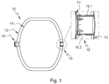
- a hydrogen tank 10 comprises an outer enclosure 12, an inner enclosure 14 positioned in the outer enclosure 12, thermal insulation between the outer and inner enclosures 12, 14 as well as two diametrically opposed connecting systems 16, 16', connecting the outer and inner enclosures 12, 14.
- the inner enclosure 14 contracts much more than the outer enclosure 12. Consequently, at least one of the two connecting systems 16 is configured to allow movement of the inner enclosure 14 relative to the outer enclosure 12 in a direction of movement.
- a first 16' link system (the one on the left on the figure 1 ) is rigid and does not allow any relative movement between the outer and inner enclosures 12, 14 while a second connection system 16 (the one on the right on the figure 1 ) allows relative movement between the outer and inner enclosures 12, 14.
- This second connection system 16 comprises a female sleeve 18.1 secured to the outer enclosure 12 as well as a male sleeve 18.2 secured to the internal enclosure 14 and configured to slide in the female sleeve 18.1.
- These two female and male sleeves 18.1, 18.2 are coaxial and have axes coincident with the direction of movement.
- the present invention aims to remedy all or part of the drawbacks of the prior art.
- the subject of the invention is a tank comprising an external enclosure, an internal enclosure positioned in the external enclosure as well as first and second connecting systems, diametrically opposed, connecting the external and internal enclosures, the external and internal enclosures moving relative to each other in a direction of movement in operation.
- At least one of the first and second connecting systems comprises a central part connected to a first element from among the outer enclosure and the inner enclosure as well as at least three blades distributed around the central part, each blade extending between a first end connected to the central part and a second end which has a head connected to a second element, different from the first element, among the external enclosure and the internal enclosure, each blade being flexible enough to deform elastically between its first and second ends in the direction of movement.
- the blades of the connection system thanks to their ability to deform elastically, allow the external and internal enclosures to move relative to each other according to the direction of movement (in particular due to the phenomena of expansion) while ensuring the absorption of radial forces between the outer and inner enclosures. Moreover, in the presence of hydrogen in the cryogenic state in the internal containment, the latter deviates from the external containment in line with the connection system due to the retraction of the internal containment linked to the reduction in its temperature.
- the profile of the blades is curved and such that the blades are positioned substantially in a transverse plane when the internal enclosure has contracted due to the presence of hydrogen in the cryogenic state in said internal enclosure, makes it possible to limit the stresses in the blades, in the presence of hydrogen in the cryogenic state in the internal enclosure, to a much lower level than if the blades did not have such a curved profile.
- this curved profile thus allows the blades to deform without high stresses during the retraction of the internal enclosure. It also allows the blades to deform without high stresses when the temperature of the blades decreases under the effect of thermal conduction from the internal enclosure containing hydrogen in the cryogenic state.
- the central part is connected to the internal enclosure, each head being connected to the external enclosure.
- the central part comprises a support integral with the internal enclosure, a ring connected to the external enclosure via the blades and configured to be positioned around the support as well as a fastening system configured to immobilize the ring with respect to the support at least along the direction of movement, the connection system comprising first and second dissociable parts, the first part comprising the ring, the blades as well as the heads, the second part comprising the support.
- the support comprises a base fixed to the internal enclosure by fastening elements as well as a tubular portion integral with the base, having an axis substantially coinciding with the direction of movement and on which the ring.
- the fastening system comprises a threaded section provided at the level of the tubular portion as well as a nut configured to be screwed onto the threaded section.
- the fastening system comprises a system for locking the nut in rotation and/or a compression ring inserted between the nut and the ring and/or two shear rings positioned on either side of the ring.
- the outer enclosure comprises an opening in line with the support as well as a cover to close off the opening.
- the external enclosure comprises, for each head, a clip with a U-section, comprising a base against which the head is fixed, positioned in a substantially transverse plane, as well as legs connecting the base to the enclosure external.
- connection system comprises a safety system comprising a female sleeve secured to the outer enclosure which has an axis coinciding with the direction of movement as well as a male extension secured to the internal enclosure, positioned in the female sleeve, the male extension and the female sleeve being dimensioned so that there is clearance all around the male extension between the female sleeve and the male extension when the blades are not damaged.
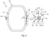
- a reservoir 20 comprises an external enclosure 22, an internal enclosure 24 positioned in the external enclosure 22 as well as first and second connecting systems 26, 26', diametrically opposed, connecting the external and internal enclosures 22, 24.
- the tank 20 is suitable for storing hydrogen in the cryogenic state in the internal enclosure 24.
- the tank 20 comprises thermal insulation between the external and internal enclosures 22, 24.
- the second connection system 26' is rigid and identical to the rigid connection system of the prior art. According to a second configuration, the first and second connection systems 26, 26' are identical.
- a longitudinal direction is parallel to the direction of movement DD.
- a radial direction is perpendicular to the direction of movement DD.
- a transverse plane is a plane perpendicular to the direction of movement DD.
- a longitudinal plane contains the direction of movement DD.
- the connection system 26 comprises a central part 28 connected to a first element from among the outer enclosure 22 and the inner enclosure 24, several blades 30 which each extend between first and second ends, for each blade 30 the first end being connected to the central part 28, the second end having a head 32 connected to a second element, different from the first element, among the outer enclosure 22 and the inner enclosure 24.
- Each blade 30 is radial. By radial blade, it is meant that the blade 30 is oriented in an approximately radial direction, its first and second ends being positioned in a longitudinal plane. According to this arrangement, the head 32 is offset with respect to the central part 28 along a direction comprising a component perpendicular to the direction of displacement DD.
- Each blade 30 is in the form of a strip of material. It is flexible enough to deform elastically between its first and second ends in the direction of displacement DD.
- the central part 28 is connected to the internal enclosure 24 and each head 32 is connected to the external enclosure 22.
- the outer enclosure 22 comprises a clip 34 with a U-shaped section, comprising a base 34.1 against which is fixed a head 32, positioned in a substantially transverse plane as well as legs 34.2 connecting the base 34.1 to the outer enclosure 22.
- each head 32 is connected to a fastener 34 by at least one fastening element 36 such as a screw, a bolt, a rivet or the like.
- the central part 28 comprises a support 38 secured to the internal enclosure 24, a ring 40 connected to the external enclosure 22 via blades 30 and configured to be positioned around the support 38 as well as a fixing system 42 configured to immobilize the ring 40 relative to the support 38 at least in the direction of movement DD.
- the connection system 26 comprises first and second parts 26.1, 26.2 that can be dissociated.
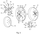
- the first part 26.1 visible on the picture 3 , includes the ring 40, the blades 30 and the heads 32 which form a single piece.
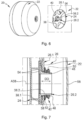
- the second part 26.2 visible on the figure 4 , includes bracket 38.
- the support 38 comprises a base 38.1 fixed to the internal enclosure 24 by fastening elements 44, such as bolts or rivets for example, as well as a tubular portion 38.2 secured to the base 38.1, having a axis A38 substantially coinciding with the direction of movement DD and on which the ring 40 is fitted.
- the base 38.1 and the tubular portion 38.2 form only one and the same piece.
- the support 38 can comprise a counter-plate positioned in the internal enclosure 24 and connected to the base 38.1 by the fixing elements 44.
- the support 38 can be metallic or made of a composite material.
- the ring 40 is substantially flat and positioned in operation in a transverse plane. It has an inside diameter substantially equal to or very slightly greater than the outside diameter of the tubular portion 38.2.
- the first part 26.1 comprising the ring 40, the blades 30 as well as the heads 32, can be metallic or made of a composite material.
- the first part 26.1 and more particularly the blades 30 are curved, the heads 32 being offset towards the internal enclosure 24 with respect to the central part 28 in the absence of constraints and being arranged substantially in the same transverse plane as the part central 28 in the presence of operating constraints.
- the blades 30 have a curved profile. In the presence of hydrogen in the internal enclosure 24, the latter deviates from the external enclosure 22 to the right of the connection system 26.
- the curved profile of the blades 30 is determined so that the blades 30 are positioned in a transverse plane, as illustrated in part (B) of the figure 9 , when the internal enclosure 24 has contracted due to the presence of hydrogen in the cryogenic state in said internal enclosure 24.
- connection system 26 comprises six blades 30 regularly distributed over the periphery of the central part 28.
- the invention is not limited to this number of blades 30.
- the connection system 26 can comprise nine blades 30, as shown in part (A) of the figure 10 , or three blades 30, as illustrated in part (C) of the figure 10 .
- the connection system 26 comprises at least three blades 30 regularly distributed around the central part 28.
- the fixing system 42 comprises a threaded section 46 provided on the outer cylindrical surface of the tubular portion 38.2 as well as a nut 48 configured to be screwed onto the threaded section 46.
- the fixing system 42 comprises a system of rotation blocking 50 of the nut 48 cooperating with the latter to immobilize it in rotation and/or a compression ring 52 inserted between the nut 48 and the ring 40.
- the fastening system 42 comprises two shear rings 54 positioned on either side of the ring 40, one of them being inserted between the base 38.1 of the support 38 and the ring 40, the other being interposed between the compression ring 52 and the ring 40.
- the outer enclosure 22 comprises an opening 56 in line with the support 38 as well as a cover 58 to close the opening 56.
- the opening 56 is dimensioned to allow the setting place of the fastening system 42 from the outside of the outer enclosure 22.
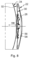
- a method of mounting tank 20 is illustrated in the figures 3 to 8 .
- the first part 26.1 is put in place by connecting each of the heads 32 to the corresponding fastener 34 using the fixing elements 36, as illustrated in the picture 3 .
- the base 38.1 of the support 38 is fixed to the internal enclosure 24 thanks to the fixing elements 44, as illustrated in the figure 4 .
- the internal enclosure 24 is positioned in the external enclosure 22 by positioning the ring 40 of the first part 26.1 around the tubular portion 38.2 of the support 38, as illustrated in the figure 5 And 6 .
- the latter is made in two parts which are assembled after the installation of the internal enclosure 24.
- the components of the fastening system 42 are introduced via the opening 56 and put in place to immobilize the ring 40 with respect to the support 38 in the direction of movement DD.
- the opening 56 is closed by fixing the cover 58 to the outer enclosure 22 all around the opening 56 by any suitable means, such as by welding for example.
- the blades 30 of the connection system 26 allow the outer and inner enclosures 22, 24 to move relative to each other in the direction of movement DD due to expansion phenomena. In addition, the blades 30 take up the radial forces (oriented perpendicular to the direction of movement DD) between the outer and inner enclosures 22, 24.
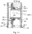
- connection system 26 comprises a safety system 60 allowing the outer enclosure 22 to support the inner enclosure 24 in the event of the blades 30 breaking.
- This connection system 26 comprises a female sleeve 60.1 secured to the outer enclosure 22, more particularly its cover 58, having an axis A60.1 coinciding with the direction of movement DD as well as a male extension 60.2, integral with the internal enclosure 24, configured to be positioned in the female sleeve 60.1.
- the female sleeve 60.1 and the male extension 60.2 are dimensioned so that in the absence of contraction of the internal enclosure 24, the male extension 60.2 does not interfere with the cover 58 and that in presence of a contraction of the internal enclosure 24, part of the male extension 60.2 is still positioned in the female sleeve 60.1.
- the female sleeve 60.1 and the male extension 60.2 are also dimensioned so that there remains a clearance all around the male extension 60.2 between the latter and the female sleeve 60.1, when the blades 30 are not damaged, for that the security system 60 does not induce any friction between the female sleeve 60.1 and the male extension 60.2.
- the male extension 60.2 can be an extension of the support 38, more particularly of its tubular portion 38.2.
- the male extension 60.2 is a separate tube from the support 38 fitted into the tubular portion 38.2 of the support 38.
Landscapes
- Engineering & Computer Science (AREA)
- Mechanical Engineering (AREA)
- General Engineering & Computer Science (AREA)
- Physics & Mathematics (AREA)
- Thermal Sciences (AREA)
- Filling Or Discharging Of Gas Storage Vessels (AREA)
Applications Claiming Priority (1)
| Application Number | Priority Date | Filing Date | Title |
|---|---|---|---|
| FR2201665 | 2022-02-25 |
Publications (1)
| Publication Number | Publication Date |
|---|---|
| EP4235012A1 true EP4235012A1 (de) | 2023-08-30 |
Family
ID=81448915
Family Applications (1)
| Application Number | Title | Priority Date | Filing Date |
|---|---|---|---|
| EP23156204.2A Pending EP4235012A1 (de) | 2022-02-25 | 2023-02-13 | Tank mit innen- und aussenräumen sowie mindestens einem verbindungssystem mit flexiblen radialen lamellen zur verbindung dieser behälter |
Country Status (2)
| Country | Link |
|---|---|
| US (1) | US12078293B2 (de) |
| EP (1) | EP4235012A1 (de) |
Families Citing this family (1)
| Publication number | Priority date | Publication date | Assignee | Title |
|---|---|---|---|---|
| FR3146503A1 (fr) * | 2023-03-10 | 2024-09-13 | Airbus Operations (S.A.S.) | Réservoir comprenant des enceintes interne et externe ainsi qu’au moins un système de liaison linéaire annulaire reliant lesdites enceintes |
Citations (6)
| Publication number | Priority date | Publication date | Assignee | Title |
|---|---|---|---|---|
| US3241705A (en) * | 1963-08-19 | 1966-03-22 | Air Reduction | Container |
| US3446388A (en) * | 1966-04-15 | 1969-05-27 | Ryan Ind Inc | Cryogenic tank support means |
| CA2441775A1 (en) * | 2003-09-23 | 2003-11-17 | Westport Research Inc. | Container for holding a cryogenic fluid |
| WO2014015969A1 (de) * | 2012-07-25 | 2014-01-30 | Ziemann International GmbH | Transportbehälter für kryogene fluide |
| WO2014161899A1 (de) * | 2013-04-05 | 2014-10-09 | Cryoshelter Gmbh | Aufhängevorrichtung für einen in einem aussenbehälter thermisch isoliert angeordneten innenbehälter und behälteranordnung |
| WO2017190846A1 (de) * | 2016-05-04 | 2017-11-09 | Linde Aktiengesellschaft | Transportbehälter |
Family Cites Families (5)
| Publication number | Priority date | Publication date | Assignee | Title |
|---|---|---|---|---|
| US3425585A (en) * | 1967-05-24 | 1969-02-04 | Process Eng Inc | Support system for cryogenic containers |
| US3764036A (en) * | 1970-12-02 | 1973-10-09 | Ametek Inc | Cryogenic liquid storage systems |
| US3696959A (en) * | 1971-01-11 | 1972-10-10 | Lox Equip | Cryogenic storage vessel constructed of dissimilar materials |
| US6015106A (en) * | 1998-09-01 | 2000-01-18 | 3M Innovative Properties Company | Apparatus for controllably breaking hollow spheres |
| GB2452910B (en) * | 2007-09-18 | 2012-11-21 | T Baden Hardstaff Ltd | Storage tank assembly |
-
2023
- 2023-02-13 EP EP23156204.2A patent/EP4235012A1/de active Pending
- 2023-02-21 US US18/172,079 patent/US12078293B2/en active Active
Patent Citations (6)
| Publication number | Priority date | Publication date | Assignee | Title |
|---|---|---|---|---|
| US3241705A (en) * | 1963-08-19 | 1966-03-22 | Air Reduction | Container |
| US3446388A (en) * | 1966-04-15 | 1969-05-27 | Ryan Ind Inc | Cryogenic tank support means |
| CA2441775A1 (en) * | 2003-09-23 | 2003-11-17 | Westport Research Inc. | Container for holding a cryogenic fluid |
| WO2014015969A1 (de) * | 2012-07-25 | 2014-01-30 | Ziemann International GmbH | Transportbehälter für kryogene fluide |
| WO2014161899A1 (de) * | 2013-04-05 | 2014-10-09 | Cryoshelter Gmbh | Aufhängevorrichtung für einen in einem aussenbehälter thermisch isoliert angeordneten innenbehälter und behälteranordnung |
| WO2017190846A1 (de) * | 2016-05-04 | 2017-11-09 | Linde Aktiengesellschaft | Transportbehälter |
Also Published As
| Publication number | Publication date |
|---|---|
| US20230272879A1 (en) | 2023-08-31 |
| US12078293B2 (en) | 2024-09-03 |
Similar Documents
| Publication | Publication Date | Title |
|---|---|---|
| EP0604312B1 (de) | Elastischer Ring mit Fertiganzeige für eine Verbindung | |
| EP3553331B1 (de) | Verbindungsvorrichtung, die zwischen mindestens zwei teilen schwenkbar ist, luftfahrzeug, das eine abdeckung umfasst, die mit dieser schwenkbaren verbindungsvorrichtung ausgestattet ist | |
| FR2919691A1 (fr) | Agrafe d'epinglage a vis et son utilisation pour la fixation temporaire d'une grille de percage sur des elements a assembler | |
| FR2847623A1 (fr) | Systeme de boulonnage visant a limiter la flexion des boulons. | |
| FR2669709A1 (fr) | Dispositif de raccord, notamment pour l'assemblage d'une durite a un echangeur de chaleur de vehicule automobile. | |
| EP1950392A1 (de) | Vorrichtung zum Zusammenbau von zwei Einheiten, beispielsweise für den Stator eines Turbotriebwerks | |
| FR2923541A1 (fr) | Vanne de decharge dans une turbomachine | |
| EP4215791B1 (de) | Vorrichtung zum verbinden zweier doppelwandleitungen und wasserstoffleitung mit dieser verbindungsvorrichtung | |
| EP0898551B1 (de) | System zum sperren einer relativen bewegung zwischen zwei körpern, in zumindest einem sinn einer vorgegebenen richtung | |
| EP3521174A1 (de) | Anordnung für eine flugzeug-motorbefestigung, die eine gelenkachse umfasst, die von einer gabel gehalten wird und nicht verschiebbar ist | |
| EP3084140B1 (de) | Führungsarm für gegenstände mit länglicher form, insbesondere für eine turbomaschine | |
| CA2777285C (fr) | Element de connexion electrique de turbomachine | |
| EP2003384B1 (de) | Anschlusssystem, das Sicherheitsbefestigungselemente umfasst | |
| FR2899658A1 (fr) | Dispositif de serrage | |
| EP0030180A1 (de) | Röhrenverbindungsvorrichtung | |
| EP4428430B1 (de) | Tank mit innen- und aussenräumen sowie mindestens einem ringförmigen linearen verbindungssystem zur verbindung dieser behälter | |
| FR2781849A1 (fr) | Dispositif a rattrapage de jeu pour fixation d'une piece | |
| EP1605195B1 (de) | Rohrkupplungssystem und dazu gehöriges Montageverfahren | |
| FR2799515A1 (fr) | Systeme a rattrapage de jeu pour fixer deux pieces l'une a l'autre au moyen d'un organe de fixation du type a vis | |
| FR2944538A1 (fr) | Attache volante de support et de fixation de structure sur une paroi, munie d'un tampon d'appui axial. | |
| FR2926613A1 (fr) | Disque de soufflante de turbomachine | |
| FR3152050A1 (fr) | Support comportant une colonne et une tête reliée à la colonne par un système de liaison par emboîtement | |
| FR2640349A1 (fr) | Collier de fixation de tuyauteries | |
| EP3938667B1 (de) | Pyrotechnische vorrichtung zum lösen von muttern | |
| FR3094047A3 (fr) | Liaison entre deux éléments montés articulés l’un à l’autre. |
Legal Events
| Date | Code | Title | Description |
|---|---|---|---|
| PUAI | Public reference made under article 153(3) epc to a published international application that has entered the european phase |
Free format text: ORIGINAL CODE: 0009012 |
|
| STAA | Information on the status of an ep patent application or granted ep patent |
Free format text: STATUS: EXAMINATION IS IN PROGRESS |
|
| 17P | Request for examination filed |
Effective date: 20230213 |
|
| AK | Designated contracting states |
Kind code of ref document: A1 Designated state(s): AL AT BE BG CH CY CZ DE DK EE ES FI FR GB GR HR HU IE IS IT LI LT LU LV MC ME MK MT NL NO PL PT RO RS SE SI SK SM TR |
|
| RBV | Designated contracting states (corrected) |
Designated state(s): AL AT BE BG CH CY CZ DE DK EE ES FI FR GB GR HR HU IE IS IT LI LT LU LV MC ME MK MT NL NO PL PT RO RS SE SI SK SM TR |
|
| GRAP | Despatch of communication of intention to grant a patent |
Free format text: ORIGINAL CODE: EPIDOSNIGR1 |
|
| STAA | Information on the status of an ep patent application or granted ep patent |
Free format text: STATUS: GRANT OF PATENT IS INTENDED |
|
| GRAS | Grant fee paid |
Free format text: ORIGINAL CODE: EPIDOSNIGR3 |
|
| INTG | Intention to grant announced |
Effective date: 20260402 |
|
| GRAA | (expected) grant |
Free format text: ORIGINAL CODE: 0009210 |
|
| STAA | Information on the status of an ep patent application or granted ep patent |
Free format text: STATUS: THE PATENT HAS BEEN GRANTED |