EP4235037A1 - Hotte aspirante - Google Patents
Hotte aspirante Download PDFInfo
- Publication number
- EP4235037A1 EP4235037A1 EP23153034.6A EP23153034A EP4235037A1 EP 4235037 A1 EP4235037 A1 EP 4235037A1 EP 23153034 A EP23153034 A EP 23153034A EP 4235037 A1 EP4235037 A1 EP 4235037A1
- Authority
- EP
- European Patent Office
- Prior art keywords
- hob
- height
- fume hood
- adjustable element
- designed
- Prior art date
- Legal status (The legal status is an assumption and is not a legal conclusion. Google has not performed a legal analysis and makes no representation as to the accuracy of the status listed.)
- Pending
Links
Images


Classifications
-
- F—MECHANICAL ENGINEERING; LIGHTING; HEATING; WEAPONS; BLASTING
- F24—HEATING; RANGES; VENTILATING
- F24C—DOMESTIC STOVES OR RANGES ; DETAILS OF DOMESTIC STOVES OR RANGES, OF GENERAL APPLICATION
- F24C15/00—Details
- F24C15/20—Removing cooking fumes
- F24C15/2042—Devices for removing cooking fumes structurally associated with a cooking range e.g. downdraft
Definitions
- the invention relates to a fume hood, a kitchen worktop or a hob with such a fume hood and a cooking system with a kitchen worktop or a hob and with such a fume hood.
- Cooking usually produces vapors which, in addition to water vapor, can also contain fat. This applies similarly to frying, which can also lead to the formation of vapors, which can contain fat and odors in particular. These vapors can also be referred to as haze, kitchen exhaust air or vapors.
- an air flow can also be generated with a fume hood to remove the vapor and this can be discharged to the outside or released back into the kitchen as cleaned air after it has been filtered.
- Extractor hoods are therefore a type of extractor hood.
- Such extractor hoods have the advantage over the previously described extractor hoods that no device has to be arranged above the hob, which the user may perceive as visually disturbing. Installation space can also be saved in this area. Instead, the functions of the hob and its extractor can be integrated into a kitchen appliance as an integrated extractor hood, so that the extractor hood can be dispensed with as an additional kitchen appliance. This can also save costs. Alternatively, a separate extractor hood can be placed in the kitchen worktop, which can be less of a nuisance to the user than a hanging extractor hood.
- the suction opening can be optically enhanced by means of a grid, which at the same time can at least partially prevent objects from falling into the air duct from above. This does not close the intake opening, so that the air can be removed at any time in this case.
- the suction opening can be closed manually by the user, e.g. with a sheet metal blank or with a glass plate as a cover or as a closing element, by placing the cover on the suction opening from above or inserting it into its edge.
- the disadvantage here is that the user has to remove the cover before use in order to be able to use the extractor hood.
- the user should also put the cover back on the suction opening of the extractor hood after use in order to be able to use its properties.
- the removed cover can become misplaced, requiring the user to search for it, which can involve additional effort.
- rotatably mounted covers which can be rotated, for example, by about 90° by means of a corresponding mechanism, in order to be in a to close the suction opening in a horizontal orientation and to release the suction opening for use in a vertical orientation.
- This can be done automatically by means of a drive, so that the user does not have to do anything for this.
- the rotatable cover can be made in one piece or in two pieces. The disadvantage here is that this type of cover can cause additional costs for the rotary mechanism, the drive and its control. Objects can also fall into the air duct from above when it is open.
- the cover can also be moved vertically upwards away from the cooktop in its horizontal alignment in order to release the suction opening laterally for sucking in the vapor.
- This can prevent objects from falling directly into the air duct from above, since this direction can remain blocked by the cover both when not in use and when in use.
- a vertical movement can require more complex mechanics than a rotary movement.
- the user can also find the cover projecting upwards to be visually disturbing.
- the cover which extends vertically upwards, can impede the user when using the hob and, for example, collide with the cookware located there or move it and/or tip it over. This also applies to rotatable covers, which protrude when in use.
- the user can also have a direct view of the intake opening and the air duct, so that the air duct is in the user's direct field of vision.
- a filter or the like arranged in the air duct can thus have to be viewed by the user, which can be optically disturbing for the user, particularly if the air duct and/or the filter is dirty.
- the extractor hoods are of particular importance, since in many kitchens they can clearly catch the customer's eye due to their size and their exposed location. There is therefore a need for action, especially with extractor hoods, in order to integrate the kitchen into the living room as unobtrusively as possible.
- extractors are therefore also designed as downdrafts so that they can be integrated vertically into the worktop next to the hob so that they can be extended for use and otherwise sunk flush with the worktop. In this way, too, an extractor hood can be created which, at least when not in use, can be perceived as little as possible or not at all.
- the DE 10 2018 130 828 A1 describes a fume hood for extracting fumes below the level of a kitchen worktop and/or a hob with at least one suction opening which is designed to be arranged in the kitchen worktop and/or in the hob plate of the hob in a flow-permeable manner, with the fume hood being formed to draw in an air flow from above the kitchen worktop and/or the hob plate through the suction opening, and with a closure element which is designed to release and close the suction opening.
- the closure element is also designed to be lowered in height purely translationally or translationally and rotationally in order to release the suction opening.
- the invention therefore faces the problem of expanding or improving the possibilities of extractor hoods.
- the possibilities for sucking off vapors and/or other air flows are to be expanded or improved.
- This should be able to be done both for hobs with an integrated extractor hood and for extractor hoods as separate kitchen appliances. In any case, this should preferably be able to be implemented as simply, inexpensively, space-savingly as possible, visually unobtrusively or appealingly and/or intuitively to operate.
- an alternative to known extractor hoods should be created.
- the invention thus relates to an extractor hood for sucking off a stream of vapors below the level of a kitchen worktop and/or a hob.
- the horizontal surface or upper side of the kitchen worktop or hob is to be regarded as the plane thereof.
- the fume hood can be designed in one piece with the hob, in which case the hob plate in particular can have both the hotplates of the hob and the fume hood.
- the fume hood can also be designed as a separate module, which can be arranged in a kitchen worktop near a hob. This can increase the design freedom.
- the fume hood has a frame which is designed to be permanently connected to the kitchen worktop and/or the hob.
- a frame can also be referred to as a frame.
- the frame can be used to mount the extractor on the kitchen worktop or on a piece of kitchen furniture below the kitchen worktop or to mount the extractor below the hob plate or hob.
- the fume hood also has a height-adjustable element with a suction opening. Through the suction opening of the height-adjustable element, the vapor flow can be sucked into the height-adjustable element and below the level of the kitchen worktop or hob. This can be done in particular by means of an air extraction element, for example in the form of a fan or a blower of the fume hood, as will be described in more detail below.
- the height-adjustable element is designed to be moved in the vertical direction in relation to the frame by means of a, preferably electric, drive, so that the height-adjustable element, preferably an extractor hood cover of the height-adjustable element, in the vertical direction in relation to the plane of the kitchen worktop or the hob offset downwards, can be positioned flush and offset upwards.
- the extractor hood according to the invention is designed to move a height-adjustable element both up and down in the vertical direction relative to the kitchen worktop or relative to the hob through an opening in the kitchen worktop, the hob or the extractor hood itself, so that the height-adjustable element or whose surface or upper side, which can also be referred to as an extractor hood cover, can be moved in at least three positions or positions of different heights relative to the level of the kitchen worktop or hob.
- it can be positioned so that it is flush with the surface, so that the corresponding opening is closed and a smooth finish is achieved throughout common surface of the extractor hood and the kitchen worktop or hob can be created.
- the height-adjustable element or its extractor hood cover can be positioned offset in the vertical direction both upwards and downwards compared to the flush positioning, which can open up different possible uses.
- the height-adjustable element can be offset upwards in the vertical direction in order to bring the suction opening as close as possible to the top edge of the cooking utensil, which can promote the suction effect.
- display and/or operating elements can also be visible or accessible to the user more easily or at all. If the height-adjustable element is positioned offset downwards in the vertical direction, the air flow can also be sucked off, but this is visually much less noticeable to the user than in the position offset upwards.
- the fume hood is designed to suck in the flow of vapors through the suction opening below the level of the kitchen worktop or the hob when the height-adjustable element is offset upwards in the vertical direction relative to the level of the kitchen worktop or the hob.
- the fume hood is designed to suck in the flow of vapors through the suction opening below the level of the kitchen worktop or the hob when the height-adjustable element is offset downwards in the vertical direction relative to the level of the kitchen worktop or the hob.
- the fume hood is designed to draw in the fume flow laterally past a fume hood cover of the height-adjustable element through the suction opening.
- This can be a particularly simple way of allowing the flow of vapor to be sucked in in this position.
- This can also include that the flow of vapors can be sucked in below the level of the kitchen worktop or hob through an air duct, which is not part of the height-adjustable element and is formed in particular by the frame or is part of the frame, if the height-adjustable element is positioned offset downwards.
- the extractor has an actuatable fixing element which is designed to fix the height-adjustable element in the vertical direction relative to the frame in at least one position, preferably in the flush position.
- an actuatable fixed element can be implemented, for example, by means of a pin, hook or the like, which can be moved, for example, by means of an electric drive in order to engage in at least one corresponding recess of the height-adjustable element or to release it.
- the corresponding positioning can be supported or secured in order to be able to hold this positioning more easily and securely, in particular when the height-adjustable element is loaded from above, for example by a cooking utensil, kitchen appliance or the like arranged there.
- Different positions can also be secured in this way, in that the height-adjustable element has corresponding recesses.
- the extractor hood is designed to suck in a flow of cooling air below the level of the kitchen worktop or hob when the height-adjustable element is offset upwards, downwards and/or in the vertical direction relative to the level of the kitchen worktop or hob is positioned flush with the level of the kitchen worktop or hob.
- the extractor can generate a flow of cooling air below the kitchen worktop or the hob in addition or as an alternative to the vapor flow, for example to be able to cool electrical or electronic components of the hob, such as the induction coils of an induction hob.
- the cooling effect of the cooling air flow can be used precisely when the hob is in operation.
- the flow of cooling air can also be generated solely when the height-adjustable element is flush with the kitchen worktop or hob and the corresponding opening is therefore sealed at least substantially in an airtight manner.
- the cooling effect of the cooling air flow can be used, for example, as a time-limited after-run after the hob has been in operation.
- the height-adjustable element has a display and/or operating element, which is visible and/or accessible to a user only in the offset position.
- This can be implemented using separate buttons, knobs, switches, toggles and the like as operating elements in combination with a display as a display element, for example a liquid crystal display.
- a display for example a liquid crystal display.
- Single-colored or multi-colored lights can also be added or can alternatively be used as display elements.
- a touchscreen display can also be provided, which can combine operating and display options.
- display and operating options can be created for the user in this way, which are only available when the height-adjustable element is positioned offset upwards. This can improve the visual impression of the extractor for the user and in particular allow the extractor to disappear from view as completely as possible if the height-adjustable element is positioned flush or offset downwards.
- the fume hood has an air extraction element, preferably a fan, which is designed to generate the flow of fumes, preferably and/or a flow of cooling air.
- the air suction element can preferably be arranged in a fixed manner on the frame, which can simplify implementation.
- a fan can also be referred to as a blower.
- the fume hood is designed to automatically operate the air extraction element in the downwardly offset position for a predetermined period of time.
- a corresponding after-running of the extraction of the flow of vapors after operation of the hob can be generated in order to continue to remove vapors, odors and the like from the area above the vapor extraction hood for a predetermined limited period of time.
- the extractor can be operated in a way that is comparatively inconspicuous to the user due to the downwardly offset positioning of the height-adjustable element.
- the fume hood is designed to automatically move the height-adjustable element into the flush, final position after the predetermined period of time has elapsed.
- the opening can thus be closed after the run-on has ended and the visual impression for the user can thereby be further improved.
- the fume hood is designed to operate the air extraction element in the upwards offset position with a greater extraction capacity than in the downwards offset position.
- the fume hood is designed to operate the air extraction element in the upwardly offset position and/or in the downwardly offset position with a greater extraction capacity than in the flush position.
- the fact can be taken into account that in the flush final positioning there is no extraction of a flow of vapor below the level of the kitchen worktop and bhw. or the hob and thus only a flow of cooling air to cool the electronics or the coils may be required, which can be comparatively weak.
- a comparatively strong suction capacity can thus be used as described above in the position offset upwards.
- a medium scour performance may be appropriate as previously described.
- a comparatively weak flow of cooling air can be sufficient.
- the fume hood is designed to automatically position the height-adjustable element depending on the use of the kitchen worktop or the hob, preferably depending on the output of at least one hotplate of the hob.
- a particularly effective extraction of the flow of vapors can take place in the position offset upwards during use of the cooking area and a rather inconspicuous extraction of the flow of vapors, for example as a follow-up after the use of the cooking area, in the positioning offset downwards.
- the extractor has a control unit which is designed to operate the preferably electric drive of the height-adjustable element, an actuatable fixing element, an air extraction element and/or a display and/or operating element.
- a control unit which is designed to operate the preferably electric drive of the height-adjustable element, an actuatable fixing element, an air extraction element and/or a display and/or operating element.
- Other previously described functions such as time-dependent and/or state-dependent functions of the extractor can also be carried out by the control unit.
- the present invention also relates to a kitchen worktop or hob with an extractor hood as described above.
- the extractor according to the invention can be used as an integral part of a kitchen worktop or a hob, as described above, in order to be able to use its properties and advantages in this form.
- the present invention also relates to a cooking system with a kitchen worktop or with a hob and with a fume hood as described above.
- the extractor according to the invention can be used as a separate device as before described in order to be able to use its properties and advantages by installing and using the separate extractor hood together with a kitchen worktop or hob.
- the present invention is based on the knowledge that nowadays in a fully integrated cooktop with an integrated extractor hood or in a system made up of a fully integrated extractor hood and fully integrated cooktops, the ventilation opening, the operating elements, the display elements such as a residual heat display, warning displays and the like with moving parts should be as invisible as possible.
- the number of penetrations through the worktop or through the tabletop, hereinafter collectively referred to as just the worktop, should preferably be minimized.
- a raised extraction element has advantages in terms of extraction performance due to the proximity of the extraction opening to the point where the vapor is emitted from the cooking vessels and also offers the possibility of expanded operating options such as an on/off switch that is invisible when retracted or the possibility of operation by means of a projection in the extended state.
- a design that is as understated as possible is desired in the case of fully integrated cooktops.
- filter operation is still desired, as can be the case, for example, with a fan after-running or when the device is used as an air filter, that no fan element that has been moved out of the worktop is visually present is.
- a cooktop system is provided with an element, which can at least partially be moved bidirectionally in terms of height, of an extractor element arranged essentially below the level of the worktop.
- the bidirectional movability of the height-adjustable element enables three states, which can be combined with different operating modes: flush, recessed, extended.
- the only exception to fan operation in this state may be in special operating modes for air movement below the level of the worktop, e.g. for cooling purposes or for using the ventilation technology for other connected devices such as built-in appliances (ovens, steam cookers, etc.), tumble dryers, washing machines and the like, in which fumes, steam and/or air can be extracted, possibly using filter and/or dehumidification units and/or energy recovery systems connected to the ventilation device, possibly also with a heating mode to heat the air flow .
- the present extractor-based ventilation concept can be used to integrate a cooling air supply for the worktop and/or the coils of an induction heating device in a fully integrated cooktop with an integrated extractor.
- the surface of the height-adjustable element When flush with the surface, the surface of the height-adjustable element can be used like a normal worktop.
- a mechanical lock engages when the surface is flush.
- These can be, for example, hooks, slides and/or other latching elements which can fully or partially absorb a force acting on the height-adjustable element from above.
- the fan module When retracted, the fan module can be operated to suck off fluids such as air, vapors, steam and the like.
- the input/output options may be limited, as UI elements (user interface elements) on the extended, height-adjustable element or UI elements that are wholly or partially based on projection cannot be used when retracted. Whether and to what extent the restrictions have an effect can depend on the existing input/output options such as knobs, removable controls, controls in openings in the worktop, controls under a glass ceramic surface, residual heat indicators with openings through the worktop, cooking zone markings with Worktop openings in combination with residual heat indicators, fixed (e.g. engraved) cooking zone markings and the like in the hob system.
- the hob system may not have any other input/output elements and markings. Since cooking is not possible without the possibility of intervention such as power control, activation or deactivation of the hob and the like, the sunken operating mode can only be used for additional functions such as fan run-on or an air cleaning function such as removing pollen, smoke, odours, viruses and the like can be used from the air. These functions can either be time-controlled, e.g. Since the last case involves a remote control, only the fan function can be operated without using the heating functions.
- the closing element or the height-adjustable fan element can be moved automatically.
- the height-adjustable element can be moved to the flush position after the fan run-on has finished.
- the cooking system can have additional input/output elements and markings.
- the cooking system can, for example, have built-in knobs arranged in the front as operating elements.
- the hob system can be switched on and off and the power adjusted using these controls. This means that no input/output elements need to be positioned on the height-adjustable element of the extractor unit.
- This mode can then essentially be characterized by a greater distance between the fume intake opening and the location where the fumes are generated and possibly reduced cross-sections for the passage of air.
- a possible embodiment of this operating mode can then provide that operation with a lowered, height-adjustable element is used for additional functions and cooking processes with low vapor production or low odors, such as controlled cooking with a lid, and operation with a raised, height-adjustable element is used for cooking processes with strong odors, such as roasting processes can.
- the extractor unit can be switched to the various operating modes manually. For example, a manual adjustment of the position of the height-adjustable element of the extractor unit can be provided via an input element.
- the height-adjustable unit automatically moves to the optimal position.
- Exactly how this works can be configured by the user or specified in advance. For example, it is conceivable to permanently assign certain operating modes of the fan element to certain operating modes of the hob element(s).
- the cooking system can be operated in the sunken extraction mode if a low power level and/or a temperature typical for cooking, e.g. B. ⁇ 120 ° C is present.
- the recessed extractor hood mode can also be used if, after the cooking process has been completed, a fan run-on to remove residual odors from the air can be beneficial.
- the recessed extractor hood mode can be activated by other devices such as a ventilation system with an air quality sensor.
- the extended mode can be used when there is a high temperature typical for frying.
- a VOC sensor volatile organic compounds or air pollutant sensor
- a moisture sensor can detect the fat content, the steam content and/or the content of odorous substances in the vapor. If, for example, a high concentration of fat, moisture and/or odors is detected in a sunken, height-adjustable element, the control unit of the cooking system can switch the cooking system to a mode suitable for high suction power. This can, for example, include a step in which the height-adjustable element is extended so far that optimal suction is possible.
- the described variant of a hob system with a bidirectionally height-adjustable element of a vapor extraction unit can enable a combination of optimal suction power in all operating modes in connection with a minimized visual impression for the user.
- a longitudinal direction X which can also be referred to as depth X or length X, extends.
- a transverse direction Y which can also be referred to as width Y, extends perpendicularly to the longitudinal direction X.
- a vertical direction Z which can also be referred to as the height Z and corresponds to the direction of gravity, extends perpendicularly both to the longitudinal direction X and to the transverse direction Y.
- the longitudinal direction X and the transverse direction Y together form the horizontal X, Y, which can also be referred to as the horizontal plane X, Y.
- figure 1 shows a longitudinal section through a hob 1 according to the invention with an inventive extractor 2 according to a first embodiment in a flush final positioning of a height-adjustable element 23.
- the hob 1 and the extractor 2 together form a cooking system 1, 2.
- the hob 1 is considered using the example of an induction hob 1 , the extractor hood 2 according to the invention also being able to be used with a kitchen worktop 1 .
- the hob 1 has a hob plate 10 in the form of a glass ceramic plate 10 with an opening 11 in which the fume hood 2 is arranged.
- a hotplate 12 of the hob 1 is arranged in the transverse direction Y to the side of the opening 11, see FIG Figures 5 and 6 .
- Each hotplate 12 has an induction coil 13 below the hotplate 10 in the vertical direction Z, which is arranged in a stationary manner on a holder 14 .
- the extractor hood 2 can also be referred to as a table extractor 2, a downdraft extractor 2 or a downdraft 2.
- the fume hood 2 has a frame 20 which can also be referred to as a housing 20 .
- the frame 20 is fixed underneath the hob plate 10 on the hob 1 or on its frame (not shown).
- the frame 20 forms a rectangular shaft (not labeled) in which the already mentioned height-adjustable element 23 is arranged.
- the height-adjustable element 23 in turn has a frame (not labeled) which is mounted so that it can move in the vertical direction Z relative to the frame 20 (not shown).
- An electric drive (not shown) is also provided on the side of the frame 20, which can move the height-adjustable element 23 both upwards and downwards in the vertical direction Z.
- the corresponding activation of the electric drive takes place via a control unit (not shown) of the extractor hood 2.
- the height-adjustable element 23 terminates in the vertical direction Z at the top with an extractor hood cover 26 , which can also be referred to as an extractor plate 26 or as an extractor hood closure 26 .
- the fume hood cover 26 is designed to close the opening 11 as completely as possible when positioned appropriately in the vertical direction Z, thereby terminating it flat or flush with the upper side of the hob plate 10 . By closing the opening 11, objects and liquids can be kept out of the interior of the extractor hood 2 and thus protected from dirt and damage. Due to the flush closure, the fume hood 2 can be as visually inconspicuous as possible for a user of the cooking system 1, 2. This positioning of the height-adjustable element 23 represents the state of the fume hood 2 when it is not in use.
- the height-adjustable element 23 can be fixed or held by means of an actuatable fixing element 22, so that the weight of the height-adjustable element 23 and any additional weight of objects that are present in the vertical direction Z at the top of the extractor hood cover 26, by means of the operable Fixing element 22 can be included. This can relieve the electric drive of this and ensure compliance with this flush final positioning.
- figure 2 shows the representation of the figure 1 in an upwardly offset position of the height-adjustable element 23.
- the height-adjustable element 23 is fully extended in the vertical direction Z by means of the electric drive, so that a suction opening 24 extends laterally in the transverse direction Y and along the longitudinal direction X in an elongated slot-like manner , which is arranged in the vertical direction Z close to the extractor hood cover 26 below it, is arranged well above the hob plate 10 .
- the suction openings 24 can also be referred to as air inlet openings 24 .
- a vapor flow A which can also be referred to as vapor flow A, can pass through the suction openings 24 into the interior of the height-adjustable element 23 sucked in and conveyed in the vertical direction Z downwards into the fume hood 2 .
- the corresponding air flow of the haze flow A can take place by means of an air extraction element 21, which can be arranged in the form of a fan 21 in a stationary manner at the lower end of the frame 20 and can also be operated by the control unit.
- the elevated positioning of the suction opening 24 promotes the suction of the haze flow A. This can also be supported by a correspondingly high blower output of the air suction element 21 .
- a particularly effective extraction of the haze flow A can take place.
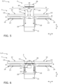
- figure 3 shows the representation of the figure 1 in a downwardly offset positioning of the height-adjustable element 23.
- the height-adjustable element 23 has been moved by means of the electric drive underneath the hob plate 10, so that the opening 11 is released by the extractor hood cover 26, but the extractor hood cover 26 protects the interior of the extractor hood 2 in the vertical direction Z continues to be closed and optically hidden.
- the frame 20 of the extractor hood 2 is designed so wide in the transverse direction Y that in this downwardly offset position of the height-adjustable element 23 the flow of vapor A can be sucked in by the air extraction element 21 on both sides around the extractor hood cover 26.
- the height-adjustable element 23 is positioned offset downwards.
- the downwardly offset positioning of the height-adjustable element 23 is not suitable for extracting the flow of vapor A during a cooking process. Instead, in the position offset downwards, the flow of vapor A can be extracted outside of a cooking process and in particular immediately after a cooking process, in order to then also clean the air.
- the height-adjustable element 23 can be automatically brought into the flush final position after the predetermined time period of the overrun has elapsed. In any case, extraction of the haze flow A can take place in a way that is visually much less noticeable to the user when the height-adjustable element 23 is positioned downwards than when the height-adjustable element 23 is offset upwards.
- the unobtrusive operation of the extractor hood 2 in the downward position of the height-adjustable element 23 can also be promoted by the fact that the air extraction element 21 in is operated in this case with a lower blower output compared to the upwardly offset positioning of the height-adjustable element 23 .
- figure 4 shows the representation of the figure 2 a fume hood 2 according to the invention according to a second embodiment.
- figure 5 shows the representation of the figure 4 as a cross section.
- figure 6 shows the representation of the figure 5 in the flush positioning of the height-adjustable element 23.
- a display/operating element 25 is provided in the vertical direction Z below the extractor hood cover 26 and next to the intake openings 24 on the end face of the height-adjustable element 23 .
- the display/control element 25 can have control elements in the form of buttons and the like, as well as at least one display element in the form of a display for showing numbers, letters, symbols and the like. The use of lights and the like is also possible.
- the display/operating element 25 is hidden from the user, see FIG figure 6 , which can improve the visual impression in this position.
- the display/control element 25 can be used by the user.
- frame openings 20a or frame openings 20a are also provided in the upper region of the frame 20, so that a further cooling air flow B can be generated or sucked in laterally in the transverse direction Y by the air extraction element 21.
- the holders 14 of the induction coils 13 also function here as air ducts 14 in order to guide the flow of cooling air B as specifically as possible around the induction coils 13 .
- the induction coils 13 can be cooled during operation, see FIG figure 5 , as well as when the extractor hood 2 is not used to extract the flow of vapor A, see figure 6 . This can be done, for example, as a time-limited run-on after a cooking process.
Landscapes
- Engineering & Computer Science (AREA)
- Chemical & Material Sciences (AREA)
- Combustion & Propulsion (AREA)
- Mechanical Engineering (AREA)
- General Engineering & Computer Science (AREA)
- Ventilation (AREA)
Applications Claiming Priority (2)
| Application Number | Priority Date | Filing Date | Title |
|---|---|---|---|
| DE102022104222 | 2022-02-23 | ||
| BE20225198A BE1030368B1 (de) | 2022-03-21 | 2022-03-21 | Dunstabzug |
Publications (1)
| Publication Number | Publication Date |
|---|---|
| EP4235037A1 true EP4235037A1 (fr) | 2023-08-30 |
Family
ID=85018439
Family Applications (1)
| Application Number | Title | Priority Date | Filing Date |
|---|---|---|---|
| EP23153034.6A Pending EP4235037A1 (fr) | 2022-02-23 | 2023-01-24 | Hotte aspirante |
Country Status (1)
| Country | Link |
|---|---|
| EP (1) | EP4235037A1 (fr) |
Citations (11)
| Publication number | Priority date | Publication date | Assignee | Title |
|---|---|---|---|---|
| JP2009089993A (ja) * | 2007-10-11 | 2009-04-30 | Panasonic Corp | 組み込み式機器 |
| DE102010042436A1 (de) | 2010-10-14 | 2012-04-19 | BSH Bosch und Siemens Hausgeräte GmbH | Kochfeld mit integrierter Dunsthaube |
| DE102011079306A1 (de) * | 2011-07-18 | 2013-01-24 | BSH Bosch und Siemens Hausgeräte GmbH | Lüftervorrichtung und Kochfeldanordnung |
| WO2013166445A1 (fr) * | 2012-05-03 | 2013-11-07 | Broan-Nutone Llc | Système à aspiration descendante |
| EP3170426A1 (fr) * | 2015-11-18 | 2017-05-24 | Richard Resch | Meuble de cuisine |
| DE102017213582A1 (de) * | 2017-08-04 | 2019-02-07 | E.G.O. Elektro-Gerätebau GmbH | Lüftervorrichtung für ein Elektrogerät, Elektrogerät und Verfahren zur Steuerung derselben |
| DE102018221339A1 (de) * | 2017-12-19 | 2019-06-19 | BSH Hausgeräte GmbH | Dunstabzugsvorrichtung, Küchengerät mit Kochfeld und Dunstabzugsvorrichtung und Verfahren zum Betreiben einer Dunstabzugsvorrichtung |
| US20190212016A1 (en) * | 2016-06-22 | 2019-07-11 | Wilhelm Bruckbauer | Device for extracting cooking vapors |
| DE102018130828A1 (de) | 2018-12-04 | 2020-06-04 | Miele & Cie. Kg | Dunstabzug |
| DE102019220302A1 (de) * | 2018-12-21 | 2020-06-25 | BSH Hausgeräte GmbH | Dunstabzugsvorrichtung für Kochfeld |
| US20240167697A1 (en) * | 2022-11-22 | 2024-05-23 | Whirlpool Corporation | Venthob with integrated induction coil |
-
2023
- 2023-01-24 EP EP23153034.6A patent/EP4235037A1/fr active Pending
Patent Citations (11)
| Publication number | Priority date | Publication date | Assignee | Title |
|---|---|---|---|---|
| JP2009089993A (ja) * | 2007-10-11 | 2009-04-30 | Panasonic Corp | 組み込み式機器 |
| DE102010042436A1 (de) | 2010-10-14 | 2012-04-19 | BSH Bosch und Siemens Hausgeräte GmbH | Kochfeld mit integrierter Dunsthaube |
| DE102011079306A1 (de) * | 2011-07-18 | 2013-01-24 | BSH Bosch und Siemens Hausgeräte GmbH | Lüftervorrichtung und Kochfeldanordnung |
| WO2013166445A1 (fr) * | 2012-05-03 | 2013-11-07 | Broan-Nutone Llc | Système à aspiration descendante |
| EP3170426A1 (fr) * | 2015-11-18 | 2017-05-24 | Richard Resch | Meuble de cuisine |
| US20190212016A1 (en) * | 2016-06-22 | 2019-07-11 | Wilhelm Bruckbauer | Device for extracting cooking vapors |
| DE102017213582A1 (de) * | 2017-08-04 | 2019-02-07 | E.G.O. Elektro-Gerätebau GmbH | Lüftervorrichtung für ein Elektrogerät, Elektrogerät und Verfahren zur Steuerung derselben |
| DE102018221339A1 (de) * | 2017-12-19 | 2019-06-19 | BSH Hausgeräte GmbH | Dunstabzugsvorrichtung, Küchengerät mit Kochfeld und Dunstabzugsvorrichtung und Verfahren zum Betreiben einer Dunstabzugsvorrichtung |
| DE102018130828A1 (de) | 2018-12-04 | 2020-06-04 | Miele & Cie. Kg | Dunstabzug |
| DE102019220302A1 (de) * | 2018-12-21 | 2020-06-25 | BSH Hausgeräte GmbH | Dunstabzugsvorrichtung für Kochfeld |
| US20240167697A1 (en) * | 2022-11-22 | 2024-05-23 | Whirlpool Corporation | Venthob with integrated induction coil |
Similar Documents
| Publication | Publication Date | Title |
|---|---|---|
| DE102010042436B4 (de) | Kochfeld mit integrierter Dunsthaube | |
| EP3338031B1 (fr) | Appareil combiné avec plaque de cuisson et dispositif d'evacuation des fumées | |
| DE102018130828A1 (de) | Dunstabzug | |
| EP3338028B1 (fr) | Appareil combiné avec plaque de cuisson et dispositif d'evacuation des fumées | |
| EP3502571B1 (fr) | Dispositif d'aspiration de fumées, appareil de cuisine pourvu de plaque de cuisson et de dispositif d'aspiration de fumées et procédé de fonctionnement d'un dispositif d'aspiration de fumées | |
| EP3168537B1 (fr) | Dispositif de cuisson avec dispositif de retrait d'échappement | |
| DE102008027470A1 (de) | Höhenverstellbare Dunstabzugshaube sowie Verfahren zum Absaugen von Wrasen | |
| DE102009030119A1 (de) | Luftreinigungseinrichtung | |
| DE102016113867A1 (de) | Haushaltgerät | |
| EP3502572B1 (fr) | Dispositif d'évacuation de fumée, appareil de cuisine pourvu de plaque de cuisson et dispositif d'évacuation de fumée et procédé de fonctionnement d'un dispositif d'évacuation de fumée | |
| DE10309226A1 (de) | Kochvorrichtung | |
| DE19814000C2 (de) | Dunstabzugshaube | |
| DE102004055945A1 (de) | Dunstabzugsvorrichtung und Verfahren zum Belüften einer Kochfläche | |
| DE202016104282U1 (de) | Downdraft-Abzugshaube mit reduziertem Raumbedarf | |
| DE4028814A1 (de) | Herd fuer kuechenbenutzung | |
| BE1030368B1 (de) | Dunstabzug | |
| DE102022104224A1 (de) | Bedienvorrichtung bzw. Dunstabzug | |
| EP4235037A1 (fr) | Hotte aspirante | |
| EP3722678B1 (fr) | Dispositif de cuisine avec meuble et appareil combiné | |
| EP2554917B1 (fr) | Dispositif d'aspiration d'air pour une table de cuisson | |
| DE102017109435A1 (de) | Bedienvorrichtung zum Bedienen eines Kochfelds und Kochfeldsystem mit einem Kochfeld und einer Bedienvorrichtung | |
| DE102015119322A1 (de) | Vorrichtung zur Absaugung von Kochdünsten | |
| DE102022104225A1 (de) | Haushaltsgerät, vorzugsweise Küchengerät | |
| BE1030370B1 (de) | Haushaltsgerät, vorzugsweise Küchengerät | |
| WO2019081265A1 (fr) | Appareil combiné comprenant un dispositif d'aspiration des fumées et une table de cuisson |
Legal Events
| Date | Code | Title | Description |
|---|---|---|---|
| PUAI | Public reference made under article 153(3) epc to a published international application that has entered the european phase |
Free format text: ORIGINAL CODE: 0009012 |
|
| STAA | Information on the status of an ep patent application or granted ep patent |
Free format text: STATUS: THE APPLICATION HAS BEEN PUBLISHED |
|
| AK | Designated contracting states |
Kind code of ref document: A1 Designated state(s): AL AT BE BG CH CY CZ DE DK EE ES FI FR GB GR HR HU IE IS IT LI LT LU LV MC ME MK MT NL NO PL PT RO RS SE SI SK SM TR |
|
| STAA | Information on the status of an ep patent application or granted ep patent |
Free format text: STATUS: REQUEST FOR EXAMINATION WAS MADE |
|
| 17P | Request for examination filed |
Effective date: 20240229 |
|
| RBV | Designated contracting states (corrected) |
Designated state(s): AL AT BE BG CH CY CZ DE DK EE ES FI FR GB GR HR HU IE IS IT LI LT LU LV MC ME MK MT NL NO PL PT RO RS SE SI SK SM TR |
|
| STAA | Information on the status of an ep patent application or granted ep patent |
Free format text: STATUS: EXAMINATION IS IN PROGRESS |
|
| 17Q | First examination report despatched |
Effective date: 20241111 |