EP4235121A2 - Système, appareil et procédé de mesure polychrome in situ de propriétés optiques d'écran solaire appliqué par voie topique - Google Patents
Système, appareil et procédé de mesure polychrome in situ de propriétés optiques d'écran solaire appliqué par voie topique Download PDFInfo
- Publication number
- EP4235121A2 EP4235121A2 EP23178567.6A EP23178567A EP4235121A2 EP 4235121 A2 EP4235121 A2 EP 4235121A2 EP 23178567 A EP23178567 A EP 23178567A EP 4235121 A2 EP4235121 A2 EP 4235121A2
- Authority
- EP
- European Patent Office
- Prior art keywords
- light
- skin
- sunscreen
- remitted
- uva
- Prior art date
- Legal status (The legal status is an assumption and is not a legal conclusion. Google has not performed a legal analysis and makes no representation as to the accuracy of the status listed.)
- Pending
Links
Images










Classifications
-
- G—PHYSICS
- G01—MEASURING; TESTING
- G01J—MEASUREMENT OF INTENSITY, VELOCITY, SPECTRAL CONTENT, POLARISATION, PHASE OR PULSE CHARACTERISTICS OF INFRARED, VISIBLE OR ULTRAVIOLET LIGHT; COLORIMETRY; RADIATION PYROMETRY
- G01J1/00—Photometry, e.g. photographic exposure meter
- G01J1/42—Photometry, e.g. photographic exposure meter using electric radiation detectors
- G01J1/429—Photometry, e.g. photographic exposure meter using electric radiation detectors applied to measurement of ultraviolet light
-
- G—PHYSICS
- G02—OPTICS
- G02B—OPTICAL ELEMENTS, SYSTEMS OR APPARATUS
- G02B6/00—Light guides; Structural details of arrangements comprising light guides and other optical elements, e.g. couplings
- G02B6/04—Light guides; Structural details of arrangements comprising light guides and other optical elements, e.g. couplings formed by bundles of fibres
- G02B6/06—Light guides; Structural details of arrangements comprising light guides and other optical elements, e.g. couplings formed by bundles of fibres the relative position of the fibres being the same at both ends, e.g. for transporting images
- G02B6/08—Light guides; Structural details of arrangements comprising light guides and other optical elements, e.g. couplings formed by bundles of fibres the relative position of the fibres being the same at both ends, e.g. for transporting images with fibre bundle in form of plate
-
- A—HUMAN NECESSITIES
- A61—MEDICAL OR VETERINARY SCIENCE; HYGIENE
- A61K—PREPARATIONS FOR MEDICAL, DENTAL OR TOILETRY PURPOSES
- A61K8/00—Cosmetics or similar toiletry preparations
- A61K8/18—Cosmetics or similar toiletry preparations characterised by the composition
- A61K8/19—Cosmetics or similar toiletry preparations characterised by the composition containing inorganic ingredients
- A61K8/27—Zinc; Compounds thereof
-
- A—HUMAN NECESSITIES
- A61—MEDICAL OR VETERINARY SCIENCE; HYGIENE
- A61K—PREPARATIONS FOR MEDICAL, DENTAL OR TOILETRY PURPOSES
- A61K8/00—Cosmetics or similar toiletry preparations
- A61K8/18—Cosmetics or similar toiletry preparations characterised by the composition
- A61K8/30—Cosmetics or similar toiletry preparations characterised by the composition containing organic compounds
- A61K8/33—Cosmetics or similar toiletry preparations characterised by the composition containing organic compounds containing oxygen
- A61K8/35—Ketones, e.g. benzophenone
-
- A—HUMAN NECESSITIES
- A61—MEDICAL OR VETERINARY SCIENCE; HYGIENE
- A61K—PREPARATIONS FOR MEDICAL, DENTAL OR TOILETRY PURPOSES
- A61K8/00—Cosmetics or similar toiletry preparations
- A61K8/18—Cosmetics or similar toiletry preparations characterised by the composition
- A61K8/30—Cosmetics or similar toiletry preparations characterised by the composition containing organic compounds
- A61K8/33—Cosmetics or similar toiletry preparations characterised by the composition containing organic compounds containing oxygen
- A61K8/36—Carboxylic acids; Salts or anhydrides thereof
- A61K8/368—Carboxylic acids; Salts or anhydrides thereof with carboxyl groups directly bound to carbon atoms of aromatic rings
-
- A—HUMAN NECESSITIES
- A61—MEDICAL OR VETERINARY SCIENCE; HYGIENE
- A61K—PREPARATIONS FOR MEDICAL, DENTAL OR TOILETRY PURPOSES
- A61K8/00—Cosmetics or similar toiletry preparations
- A61K8/18—Cosmetics or similar toiletry preparations characterised by the composition
- A61K8/30—Cosmetics or similar toiletry preparations characterised by the composition containing organic compounds
- A61K8/40—Cosmetics or similar toiletry preparations characterised by the composition containing organic compounds containing nitrogen
-
- A—HUMAN NECESSITIES
- A61—MEDICAL OR VETERINARY SCIENCE; HYGIENE
- A61K—PREPARATIONS FOR MEDICAL, DENTAL OR TOILETRY PURPOSES
- A61K8/00—Cosmetics or similar toiletry preparations
- A61K8/18—Cosmetics or similar toiletry preparations characterised by the composition
- A61K8/30—Cosmetics or similar toiletry preparations characterised by the composition containing organic compounds
- A61K8/40—Cosmetics or similar toiletry preparations characterised by the composition containing organic compounds containing nitrogen
- A61K8/41—Amines
- A61K8/411—Aromatic amines, i.e. where the amino group is directly linked to the aromatic nucleus
-
- A—HUMAN NECESSITIES
- A61—MEDICAL OR VETERINARY SCIENCE; HYGIENE
- A61Q—SPECIFIC USE OF COSMETICS OR SIMILAR TOILETRY PREPARATIONS
- A61Q17/00—Barrier preparations; Preparations brought into direct contact with the skin for affording protection against external influences, e.g. sunlight, X-rays or other harmful rays, corrosive materials, bacteria or insect stings
- A61Q17/04—Topical preparations for affording protection against sunlight or other radiation; Topical sun tanning preparations
-
- G—PHYSICS
- G01—MEASURING; TESTING
- G01J—MEASUREMENT OF INTENSITY, VELOCITY, SPECTRAL CONTENT, POLARISATION, PHASE OR PULSE CHARACTERISTICS OF INFRARED, VISIBLE OR ULTRAVIOLET LIGHT; COLORIMETRY; RADIATION PYROMETRY
- G01J1/00—Photometry, e.g. photographic exposure meter
- G01J1/02—Details
- G01J1/0233—Handheld
-
- G—PHYSICS
- G01—MEASURING; TESTING
- G01J—MEASUREMENT OF INTENSITY, VELOCITY, SPECTRAL CONTENT, POLARISATION, PHASE OR PULSE CHARACTERISTICS OF INFRARED, VISIBLE OR ULTRAVIOLET LIGHT; COLORIMETRY; RADIATION PYROMETRY
- G01J1/00—Photometry, e.g. photographic exposure meter
- G01J1/02—Details
- G01J1/0271—Housings; Attachments or accessories for photometers
-
- G—PHYSICS
- G01—MEASURING; TESTING
- G01J—MEASUREMENT OF INTENSITY, VELOCITY, SPECTRAL CONTENT, POLARISATION, PHASE OR PULSE CHARACTERISTICS OF INFRARED, VISIBLE OR ULTRAVIOLET LIGHT; COLORIMETRY; RADIATION PYROMETRY
- G01J1/00—Photometry, e.g. photographic exposure meter
- G01J1/02—Details
- G01J1/04—Optical or mechanical part supplementary adjustable parts
- G01J1/0403—Mechanical elements; Supports for optical elements; Scanning arrangements
-
- G—PHYSICS
- G01—MEASURING; TESTING
- G01J—MEASUREMENT OF INTENSITY, VELOCITY, SPECTRAL CONTENT, POLARISATION, PHASE OR PULSE CHARACTERISTICS OF INFRARED, VISIBLE OR ULTRAVIOLET LIGHT; COLORIMETRY; RADIATION PYROMETRY
- G01J1/00—Photometry, e.g. photographic exposure meter
- G01J1/02—Details
- G01J1/04—Optical or mechanical part supplementary adjustable parts
- G01J1/0407—Optical elements not provided otherwise, e.g. manifolds, windows, holograms, gratings
-
- G—PHYSICS
- G01—MEASURING; TESTING
- G01J—MEASUREMENT OF INTENSITY, VELOCITY, SPECTRAL CONTENT, POLARISATION, PHASE OR PULSE CHARACTERISTICS OF INFRARED, VISIBLE OR ULTRAVIOLET LIGHT; COLORIMETRY; RADIATION PYROMETRY
- G01J1/00—Photometry, e.g. photographic exposure meter
- G01J1/02—Details
- G01J1/04—Optical or mechanical part supplementary adjustable parts
- G01J1/0407—Optical elements not provided otherwise, e.g. manifolds, windows, holograms, gratings
- G01J1/0425—Optical elements not provided otherwise, e.g. manifolds, windows, holograms, gratings using optical fibers
-
- G—PHYSICS
- G01—MEASURING; TESTING
- G01J—MEASUREMENT OF INTENSITY, VELOCITY, SPECTRAL CONTENT, POLARISATION, PHASE OR PULSE CHARACTERISTICS OF INFRARED, VISIBLE OR ULTRAVIOLET LIGHT; COLORIMETRY; RADIATION PYROMETRY
- G01J1/00—Photometry, e.g. photographic exposure meter
- G01J1/02—Details
- G01J1/04—Optical or mechanical part supplementary adjustable parts
- G01J1/0488—Optical or mechanical part supplementary adjustable parts with spectral filtering
-
- G—PHYSICS
- G01—MEASURING; TESTING
- G01J—MEASUREMENT OF INTENSITY, VELOCITY, SPECTRAL CONTENT, POLARISATION, PHASE OR PULSE CHARACTERISTICS OF INFRARED, VISIBLE OR ULTRAVIOLET LIGHT; COLORIMETRY; RADIATION PYROMETRY
- G01J1/00—Photometry, e.g. photographic exposure meter
- G01J1/02—Details
- G01J1/08—Arrangements of light sources specially adapted for photometry standard sources, also using luminescent or radioactive material
-
- G—PHYSICS
- G01—MEASURING; TESTING
- G01J—MEASUREMENT OF INTENSITY, VELOCITY, SPECTRAL CONTENT, POLARISATION, PHASE OR PULSE CHARACTERISTICS OF INFRARED, VISIBLE OR ULTRAVIOLET LIGHT; COLORIMETRY; RADIATION PYROMETRY
- G01J1/00—Photometry, e.g. photographic exposure meter
- G01J1/10—Photometry, e.g. photographic exposure meter by comparison with reference light or electric value provisionally void
- G01J1/16—Photometry, e.g. photographic exposure meter by comparison with reference light or electric value provisionally void using electric radiation detectors
- G01J1/18—Photometry, e.g. photographic exposure meter by comparison with reference light or electric value provisionally void using electric radiation detectors using comparison with a reference electric value
-
- G—PHYSICS
- G01—MEASURING; TESTING
- G01J—MEASUREMENT OF INTENSITY, VELOCITY, SPECTRAL CONTENT, POLARISATION, PHASE OR PULSE CHARACTERISTICS OF INFRARED, VISIBLE OR ULTRAVIOLET LIGHT; COLORIMETRY; RADIATION PYROMETRY
- G01J3/00—Spectrometry; Spectrophotometry; Monochromators; Measuring colours
- G01J3/02—Details
- G01J3/0202—Mechanical elements; Supports for optical elements
-
- G—PHYSICS
- G01—MEASURING; TESTING
- G01J—MEASUREMENT OF INTENSITY, VELOCITY, SPECTRAL CONTENT, POLARISATION, PHASE OR PULSE CHARACTERISTICS OF INFRARED, VISIBLE OR ULTRAVIOLET LIGHT; COLORIMETRY; RADIATION PYROMETRY
- G01J3/00—Spectrometry; Spectrophotometry; Monochromators; Measuring colours
- G01J3/02—Details
- G01J3/0205—Optical elements not provided otherwise, e.g. optical manifolds, diffusers, windows
-
- G—PHYSICS
- G01—MEASURING; TESTING
- G01J—MEASUREMENT OF INTENSITY, VELOCITY, SPECTRAL CONTENT, POLARISATION, PHASE OR PULSE CHARACTERISTICS OF INFRARED, VISIBLE OR ULTRAVIOLET LIGHT; COLORIMETRY; RADIATION PYROMETRY
- G01J3/00—Spectrometry; Spectrophotometry; Monochromators; Measuring colours
- G01J3/02—Details
- G01J3/0205—Optical elements not provided otherwise, e.g. optical manifolds, diffusers, windows
- G01J3/0218—Optical elements not provided otherwise, e.g. optical manifolds, diffusers, windows using optical fibers
-
- G—PHYSICS
- G01—MEASURING; TESTING
- G01J—MEASUREMENT OF INTENSITY, VELOCITY, SPECTRAL CONTENT, POLARISATION, PHASE OR PULSE CHARACTERISTICS OF INFRARED, VISIBLE OR ULTRAVIOLET LIGHT; COLORIMETRY; RADIATION PYROMETRY
- G01J3/00—Spectrometry; Spectrophotometry; Monochromators; Measuring colours
- G01J3/02—Details
- G01J3/0272—Handheld
-
- G—PHYSICS
- G01—MEASURING; TESTING
- G01J—MEASUREMENT OF INTENSITY, VELOCITY, SPECTRAL CONTENT, POLARISATION, PHASE OR PULSE CHARACTERISTICS OF INFRARED, VISIBLE OR ULTRAVIOLET LIGHT; COLORIMETRY; RADIATION PYROMETRY
- G01J3/00—Spectrometry; Spectrophotometry; Monochromators; Measuring colours
- G01J3/02—Details
- G01J3/0291—Housings; Spectrometer accessories; Spatial arrangement of elements, e.g. folded path arrangements
-
- G—PHYSICS
- G01—MEASURING; TESTING
- G01J—MEASUREMENT OF INTENSITY, VELOCITY, SPECTRAL CONTENT, POLARISATION, PHASE OR PULSE CHARACTERISTICS OF INFRARED, VISIBLE OR ULTRAVIOLET LIGHT; COLORIMETRY; RADIATION PYROMETRY
- G01J3/00—Spectrometry; Spectrophotometry; Monochromators; Measuring colours
- G01J3/02—Details
- G01J3/0294—Multi-channel spectroscopy
-
- G—PHYSICS
- G01—MEASURING; TESTING
- G01J—MEASUREMENT OF INTENSITY, VELOCITY, SPECTRAL CONTENT, POLARISATION, PHASE OR PULSE CHARACTERISTICS OF INFRARED, VISIBLE OR ULTRAVIOLET LIGHT; COLORIMETRY; RADIATION PYROMETRY
- G01J3/00—Spectrometry; Spectrophotometry; Monochromators; Measuring colours
- G01J3/02—Details
- G01J3/10—Arrangements of light sources specially adapted for spectrometry or colorimetry
-
- G—PHYSICS
- G01—MEASURING; TESTING
- G01J—MEASUREMENT OF INTENSITY, VELOCITY, SPECTRAL CONTENT, POLARISATION, PHASE OR PULSE CHARACTERISTICS OF INFRARED, VISIBLE OR ULTRAVIOLET LIGHT; COLORIMETRY; RADIATION PYROMETRY
- G01J3/00—Spectrometry; Spectrophotometry; Monochromators; Measuring colours
- G01J3/28—Investigating the spectrum
- G01J3/30—Measuring the intensity of spectral lines directly on the spectrum itself
- G01J3/36—Investigating two or more bands of a spectrum by separate detectors
-
- G—PHYSICS
- G01—MEASURING; TESTING
- G01J—MEASUREMENT OF INTENSITY, VELOCITY, SPECTRAL CONTENT, POLARISATION, PHASE OR PULSE CHARACTERISTICS OF INFRARED, VISIBLE OR ULTRAVIOLET LIGHT; COLORIMETRY; RADIATION PYROMETRY
- G01J3/00—Spectrometry; Spectrophotometry; Monochromators; Measuring colours
- G01J3/28—Investigating the spectrum
- G01J3/42—Absorption spectrometry; Double beam spectrometry; Flicker spectrometry; Reflection spectrometry
-
- G—PHYSICS
- G01—MEASURING; TESTING
- G01N—INVESTIGATING OR ANALYSING MATERIALS BY DETERMINING THEIR CHEMICAL OR PHYSICAL PROPERTIES
- G01N21/00—Investigating or analysing materials by the use of optical means, i.e. using sub-millimetre waves, infrared, visible or ultraviolet light
- G01N21/17—Systems in which incident light is modified in accordance with the properties of the material investigated
- G01N21/25—Colour; Spectral properties, i.e. comparison of effect of material on the light at two or more different wavelengths or wavelength bands
- G01N21/31—Investigating relative effect of material at wavelengths characteristic of specific elements or molecules, e.g. atomic absorption spectrometry
- G01N21/33—Investigating relative effect of material at wavelengths characteristic of specific elements or molecules, e.g. atomic absorption spectrometry using ultraviolet light
-
- G—PHYSICS
- G01—MEASURING; TESTING
- G01N—INVESTIGATING OR ANALYSING MATERIALS BY DETERMINING THEIR CHEMICAL OR PHYSICAL PROPERTIES
- G01N21/00—Investigating or analysing materials by the use of optical means, i.e. using sub-millimetre waves, infrared, visible or ultraviolet light
- G01N21/84—Systems specially adapted for particular applications
- G01N21/8422—Investigating thin films, e.g. matrix isolation method
-
- G—PHYSICS
- G02—OPTICS
- G02B—OPTICAL ELEMENTS, SYSTEMS OR APPARATUS
- G02B6/00—Light guides; Structural details of arrangements comprising light guides and other optical elements, e.g. couplings
- G02B6/0001—Light guides; Structural details of arrangements comprising light guides and other optical elements, e.g. couplings specially adapted for lighting devices or systems
- G02B6/0011—Light guides; Structural details of arrangements comprising light guides and other optical elements, e.g. couplings specially adapted for lighting devices or systems the light guides being planar or of plate-like form
- G02B6/0075—Arrangements of multiple light guides
- G02B6/0076—Stacked arrangements of multiple light guides of the same or different cross-sectional area
-
- G—PHYSICS
- G02—OPTICS
- G02B—OPTICAL ELEMENTS, SYSTEMS OR APPARATUS
- G02B6/00—Light guides; Structural details of arrangements comprising light guides and other optical elements, e.g. couplings
- G02B6/04—Light guides; Structural details of arrangements comprising light guides and other optical elements, e.g. couplings formed by bundles of fibres
- G02B6/06—Light guides; Structural details of arrangements comprising light guides and other optical elements, e.g. couplings formed by bundles of fibres the relative position of the fibres being the same at both ends, e.g. for transporting images
-
- G—PHYSICS
- G02—OPTICS
- G02B—OPTICAL ELEMENTS, SYSTEMS OR APPARATUS
- G02B6/00—Light guides; Structural details of arrangements comprising light guides and other optical elements, e.g. couplings
- G02B6/24—Coupling light guides
- G02B6/255—Splicing of light guides, e.g. by fusion or bonding
-
- G—PHYSICS
- G02—OPTICS
- G02B—OPTICAL ELEMENTS, SYSTEMS OR APPARATUS
- G02B6/00—Light guides; Structural details of arrangements comprising light guides and other optical elements, e.g. couplings
- G02B6/24—Coupling light guides
- G02B6/36—Mechanical coupling means
- G02B6/3616—Holders, macro size fixtures for mechanically holding or positioning fibres, e.g. on an optical bench
- G02B6/3624—Fibre head, e.g. fibre probe termination
-
- G—PHYSICS
- G01—MEASURING; TESTING
- G01J—MEASUREMENT OF INTENSITY, VELOCITY, SPECTRAL CONTENT, POLARISATION, PHASE OR PULSE CHARACTERISTICS OF INFRARED, VISIBLE OR ULTRAVIOLET LIGHT; COLORIMETRY; RADIATION PYROMETRY
- G01J1/00—Photometry, e.g. photographic exposure meter
- G01J1/10—Photometry, e.g. photographic exposure meter by comparison with reference light or electric value provisionally void
- G01J1/16—Photometry, e.g. photographic exposure meter by comparison with reference light or electric value provisionally void using electric radiation detectors
- G01J2001/1673—Photometry, e.g. photographic exposure meter by comparison with reference light or electric value provisionally void using electric radiation detectors using a reference sample
-
- G—PHYSICS
- G01—MEASURING; TESTING
- G01J—MEASUREMENT OF INTENSITY, VELOCITY, SPECTRAL CONTENT, POLARISATION, PHASE OR PULSE CHARACTERISTICS OF INFRARED, VISIBLE OR ULTRAVIOLET LIGHT; COLORIMETRY; RADIATION PYROMETRY
- G01J1/00—Photometry, e.g. photographic exposure meter
- G01J1/42—Photometry, e.g. photographic exposure meter using electric radiation detectors
- G01J1/44—Electric circuits
- G01J2001/4446—Type of detector
- G01J2001/4453—PMT
-
- G—PHYSICS
- G01—MEASURING; TESTING
- G01J—MEASUREMENT OF INTENSITY, VELOCITY, SPECTRAL CONTENT, POLARISATION, PHASE OR PULSE CHARACTERISTICS OF INFRARED, VISIBLE OR ULTRAVIOLET LIGHT; COLORIMETRY; RADIATION PYROMETRY
- G01J3/00—Spectrometry; Spectrophotometry; Monochromators; Measuring colours
- G01J3/12—Generating the spectrum; Monochromators
- G01J2003/1213—Filters in general, e.g. dichroic, band
-
- G—PHYSICS
- G01—MEASURING; TESTING
- G01N—INVESTIGATING OR ANALYSING MATERIALS BY DETERMINING THEIR CHEMICAL OR PHYSICAL PROPERTIES
- G01N21/00—Investigating or analysing materials by the use of optical means, i.e. using sub-millimetre waves, infrared, visible or ultraviolet light
- G01N21/17—Systems in which incident light is modified in accordance with the properties of the material investigated
- G01N21/47—Scattering, i.e. diffuse reflection
- G01N21/4738—Diffuse reflection, e.g. also for testing fluids, fibrous materials
- G01N21/474—Details of optical heads therefor, e.g. using optical fibres
- G01N2021/4742—Details of optical heads therefor, e.g. using optical fibres comprising optical fibres
- G01N2021/4745—Fused bundle, i.e. for backscatter
-
- G—PHYSICS
- G01—MEASURING; TESTING
- G01N—INVESTIGATING OR ANALYSING MATERIALS BY DETERMINING THEIR CHEMICAL OR PHYSICAL PROPERTIES
- G01N21/00—Investigating or analysing materials by the use of optical means, i.e. using sub-millimetre waves, infrared, visible or ultraviolet light
- G01N21/84—Systems specially adapted for particular applications
- G01N21/8422—Investigating thin films, e.g. matrix isolation method
- G01N2021/8427—Coatings
Definitions
- the U.S. Food and Drug Administration requires that sunscreen undergo clinical testing on humans to determine the strength of the protection provided by individual formulations. This testing requires that the humans be exposed to graded levels of broadband Ultraviolet (UV) simulated sunlight in two sites: one with the sunscreen on the skin and one without the sunscreen on the skin. The ratio of the exposure dose required to cause a sunburn reaction in the two sites (with and without the sunscreen) constitutes the Sun Protection Factor (SPF).
- SPDF Sun Protection Factor
- the SPF is used to label the protectiveness of the sunscreen and allows consumers to choose between different protection levels depending on their individual needs.
- the above-described testing requires multiple high intensity exposures to the test subjects (i.e., humans) in a procedure that may last several hours to complete in order to induce the sunburn reactions for high protection (i.e., SPF) sunscreens.
- SPF high protection
- the exposed sites may exhibit marked pigmentation that may last for months in situations where exposures significantly exceed the minimal doses for erythema production.
- UVA-PF UltraViolet-A Protection Factor
- PFA Protection Factor in the UVA
- Diffuse Reflectance Spectroscopy was introduced as a way to measure the UVA protectiveness of sunscreen products on human.
- This technique generally employs two scanning monochromators - one for illumination ("excitation”) and one for measurement (“remitted”). The two monochromators are synced to each other and illuminate and measure at the same wavelength, in order to measure the transmission through thesunscreen film on the surface of the skin.
- a bifurcated fiber optic bundle is used with randomized fibers separating illumination radiation and the returning diffuse reflected radiation.
- the typical fiber optic bundle can include quartz fibers 200 microns in diameter, one half used to illuminate the skin surface, and the other half to transmit the light reflected from within the skin back to a radiometric measurement device.
- the combined bundle of fibers randomly organized at the surface of the skin can be from 2 mm to 5 mm (or more) in diameter. The larger the bundle size, the greater the amount of signal that is provided to and from the skin sampling area.
- the prior art DRS procedure requires the use of two expensive monochromators sync scanned in order to develop this full spectral assessment of the sunscreen.
- Use of sync scanning of two monochromators has several disadvantages.
- the first relates to the ability to input large amounts of "light" into the device as the entrance is typically a narrow slit, used to determine the potential resolution in wavelength units for each recorded scan measurement at a specified wavelength.
- a second limitation is the efficiency of the device in passing through the device with multiple reflections and internal slits to limit the amount of energy being passed to a narrow wavelength band. Efficiencies are low in order to define very precise and narrow wavelength bands with low stray light interference.
- Lamps with hundreds or thousands of watts are used to illuminate a double monochromator, with only a few milliwatts of defined monochromatic energy being passed through the entire system.
- DRS measurements using two double monochromator systems compound the inefficiencies in order to have very narrow monochromatic bands for the DRS measurements. Because the measurement requires taking the square root of the ratio of remitted/excitation irradiance, the overall dynamic range of the device is critically dependent on the amount of energy being available for the measurement.
- a third limitation is that since each wavelength is measured individually, the two monochromators must be scanned across the entire wavelength range, taking significant time to cover the entire range of measurements.
- a fourth limitation is that while DRS is a useful tool to evaluate UVA protection of sunscreens on human skin, it is limited in its scope to the range of approximately 320 - 400 nm as the inherent absorption properties of the skin (primarily stratum corneum and epidermis) severely diminish the amount of remitted photons in the range below 320 nm as they are irreversibly absorbed by proteins and DNA in the skin. Thus, the amount of available energy for measurement in the UVB range renders absorption measurements impossible.
- a full range (290-400 nm) spectral scan of the shape of the absorbance of the sunscreen can be determined. While the absolute magnitude (height) of the scan is unreliable using this technique, the relative shape can be reliable for assessment of the protection of the LTVB portion relative to the UVA portion.
- an improved SPF measurement system, apparatus and method have been developed to evaluate sunscreen UVA protection in vivo, eliminating the need to irradiate human subjects to assess protection in the UVA portion of the ultraviolet spectrum.
- the presently disclosed technology is a simplified approach to measuring the UVA-PF as well as SPF protection of sunscreens that eliminates certain expensive optical equipment, and is much faster to conduct.
- broad band UVA radiation can be directed onto a small area of human skin using a bifurcated fiber optic bundle, and the amount of reflected radiation remitted from the skin can be measured using a broad band UVA detector or sensor. Sunscreen can be applied to the test area and the measurement can be repeated.
- the UVA protection is easily calculated as the square root of the ratio of the two measurements.
- an improvement over prior art DRS systems is the efficiency at which the system or device of the presently disclosed technology receives light that returns to a sensor from the subject's skin due to an increased virtual aperture.
- the presently disclosed technology can employ at least two optical conduits with one or more common edges that constitute the active source and sensing element that contact at more than a single point along the extended edge of the source and the pickup conduits. Each optical conduit can be in direct contact with the patient's skin. This increased contact results in improved efficiency of receiving light remitted out of the subject's skin.
- the efficiency at which the system or device of the presently disclosed technology receives light remitted out of the subject's skin is substantially increased.
- the presently disclosed technology can employ at least two optical conduits in intimate contact with each other along a significant length which is also in contact with the skin.
- the length(s) of along which the conduits are in contact with each other and the skin constitute the active source and pickup element(s). This in an improvement over the fiber-based system of the prior art, because it greatly increases the total portion of skin generating remitted light.
- the fiber-based system of the prior art relies on a somewhat random arrangement of individual source and pickup fibers.
- the device of the presently disclosed technology can provide a low cost and simple tool to rapidly assess sunscreen efficacy without having long and laborious, skin damaging in vivo exposures to human subjects.
- the present invention relates to a method of measuring the protection of a sunscreen composition, the method comprises an exposing skin to a known intensity of polychromatic light from a light source configured to produce broad band light; measuring the amount of remitted light from the skin; applying sunscreen to the skin; exposing the skin to which the sunscreen has been applied to the known intensity of emitted polychromatic light; measuring with a photodetector the amount of light remitted from the skin to which the sunscreen has been applied; and calculating an Ultra Violet-A Protection Factor (UVA-PF) of the sunscreen by comparing the amount of light remitted from the skin with the sunscreen to the amount of light remitted from the skin without the sunscreen.
- UVA-PF Ultra Violet-A Protection Factor
- the light may be emitted and measured by a light emission and sensing device having: a light source; an emitted light conduit for conducting the emitted light to the skin; and a remitted light conduit for conducting the light remitted from the skin to a photosensor, wherein the emitted light conduit and the remitted light conduit are in contact with the skin.
- the emitted light conduit and the remitted light conduit may be in contact with each other along a distance of at least 2 mm at the surface of the skin.
- one of the at least two optical conduits has a concave surface and the other of the at least two optical conduits has a complementary convex surface, the concave and convex surface facing each other.
- the device further comprises an end fitting attached to the second end of the cover sleeve, at least a portion of the end fitting being configured to contact skin of a patient. It is an advantageous that the emitted light conduit and the remitted light conduit are separated by 10-40 microns.
- a light filter is positioned between an end of the remitted light conduit and the light sensor.
- a longitudinal axis of the emitted light conduit extends parallel to a longitudinal axis of the light feed.
- the present invention furthermore relates to a device for measuring the protection of a sunscreen
- the device comprises a light source for emitting light in the spectrum of light from which the sunscreen is intended to protect skin; an emitted light conduit for conducting the emitted light to the skin; and a remitted light conduit for conducting the light remitted from the skin to a photosensor, wherein the emitted light conduit and the remitted light conduit are in contact with the skin, and wherein the emitted light conduit and the remitted light conduit are in contact with each other along a distance of at least 2 mm at the surface of the skin.
- An advantage is that an optical pathway separating the emitted light conduit and the remitted light conduit is between 10-40 microns wide.
- optical pathway separating the emitted light conduit and the remitted light conduit is between 10-20 microns wide.
- the present invention moreover relates to a method of measuring a protection value of sunscreen using a device having a first optical conduit and a second optical conduit, the first and second optical conduits being in contact with the skin and in contact with each other along a distance of at least 2 mm at the surface of the skin, the method comprises an emitting light through the first optical conduit to the skin; and receiving remitted light through the second optical conduit from the skin.
- the method further comprises calculating an UltraViolet-A Protection Factor (UVA-PF) of the sunscreen by comparing the amount of light remitted from the skin with the sunscreen to the amount of light remitted from the skin without the sunscreen.
- UVA-PF UltraViolet-A Protection Factor
- the present invention furthermore relates to a device for measuring sunscreen protection, the device comprises a plurality of optical conduits including at least three emitting optical conduits and at least two remitting optical conduits; a homogenizer having a first end and an opposing second end, the first end being attached to the plurality of optical conduits; a light feed operatively connected the second end of the homogenizer; and at least one light detector attached to the at least two remitting optical conduits.
- the device further comprises a moisture seal on an end of the plurality of conduits opposite the homogenizer.
- the plurality of conduits includes five emitting optical conduits and four remitting optical conduits, wherein each remitting optical conduit is positioned between two of the emitting optical conduits.
- no monochromator is used.
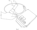
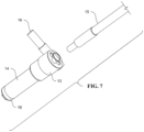
- Figs. 2-11 illustrate a system, apparatus and method for improved DRS.
- the presently disclosed technology improves upon the prior art DRS technique at least by eliminating the need for the two monochromators and the time required to sync scan across the spectrum in order to determine the detailed full spectral transmission assessment at each wavelength.
- the UVA spectrum of light from a broad band source such as, but not limited to, a filtered xenon arc or tungsten lamp
- the illuminating source is not required to pass through a monochromator to illuminate the skin, and a second monochromator to filter the remitted light, the sensitivity of the measurement radiometer can be greatly reduced, eliminating expensive electronics required for the measurement.
- Simple solidstate radiometric detectors and amplifiers can be utilized, replacing expensive and inefficient monochromator systems.
- the "excitation" light source By shaping the "excitation" light source to have the same spectral proportions to the sources used in clinical PFA evaluations, and shaping the response spectrum of the sensor to be similar to the human Persistent Pigment Darkening (PPD) action spectrum, in one embodiment no further calculations or modifications are needed to determine the PFA of the sunscreen being tested.
- the measurement can be conducted in a short period of time (e.g., less than 10 seconds and, in one embodiment, significantly less than 2 seconds) as compared with prior art DRS spectral sync scans, which typically take a much longer time, such as 1-2 minutes.
- the presently disclosed technology improves upon the "monochromatic" approach by Ruvolo et al. by substituting the polychromatic DRS system described above.
- the presently disclosed technology can utilize the in vitro spectrum of the sunscreen determined with thin film spectroscopy, and the UVA-PF determined by the polychromatic DRS measurement to scale the in vitro absorbance spectrum until it matches the UVA-PF value determined by the DRS measurement. With this scaling and the full spectrum determined by thin film spectroscopy, the proper SPF value can be attained by the usual in vitro calculations as described in Matts et al.
- the presently disclosed system in one embodiment, includes many of the same components used in the prior art DRS systems. However, one difference is that at or near the interface between the device and the subject's skin, one embodiment of the presently disclosed technology can include at least two optical conduits.
- the optical conduits can be in the form of rectilinear rods. Light pipe homogenizing rods utilize total internal reflection to homogenize non-uniform light sources regardless of their spectral characteristics.
- the optical conduits can be formed of any material that can transfer the light of interest (e.g., UV light). Examples of materials include quartz and fused silica. A suitable material can be anything that is highly transmissive. In one embodiment, more than two, such as eight, ten or even an odd number of optical conduits can be used. Every edge multiplies the remitted light signal by a factor proportional to the number of adjoining mating surfaces.
- a first end of each of the optical conduits can be connected to a fiber bundle or light feed, as used in the prior art DRS systems.
- the fiber bundle 215 e.g., a bifurcated fiber optic bundle
- the fiber bundle 215 can, in turn, be connected to a first device 250 that can house one or more light sources 252 (e.g., a UVA source), one or more filters 254 and one or more lenses 256, for example, and a second device 260 that can house one or more sensors or detectors 262, one or more filters 264 (e.g., a shaping filter), and one or more measuring devices 266.
- each optical conduit 212 is configured to directly contact the subject's skin and/or be positioned between the fiber bundle 215 and the subject's skin during testing.
- one of the optical conduits can direct incident light onto a portion of the subject's skin, and the other optical conduit can receive the reflected light from the subject's skin.
- each optical conduit can be a rod having at least one surface that faces, engages and/or complements a surface of another or the second optical conduit. These surfaces may be referred to herein as the "mating edge.”
- This configuration allows a relatively large surface or edge of the optical conduits to be in abutting contact or at least facing one another.
- the shape and compactness of the optical conduits of the presently disclosed technology allows more light, which is initially directed to the subject's skin by the first or "excitation” optical conduit and reflected by the subject's skin, to be received by the second or “remitted light” optical conduit. This proximity and configuration of the optical conduits allows for increased light reception by the device as compared to prior art DRS systems that use a fiber optic bundle to receive the reflected light.
- each optical conduit can have a rectangular (e.g., right rectangular prism) shape so that a flat surface of each optical conduit is in abutting contact with (or at least facing) a flat surface of the other optical conduit (see, e.g., Figs. 4-9B ).
- one of the optical conduits can have a concave surface, while the other optical conduit can have a complementary convex surface. The concave and convex surfaces can be in abutting contact or at least facing one another.
- each optical conduit can have a cross-sectional shape of a pentagon, a hexagon, an octagon or any other shape with at least one substantially flat or planar surface.
- the conduits are cylindrical, one contained within the other and in contact at their respective inner and outer surfaces.
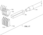
- a stack of alternating "sliver" shaped emission and remission conduits can be employed to increase the length of adjoining surfaces, such as shown in Figs. 15-17 . The above-described arrangements provide for increased surface area contact or exposure between the optical conduits.
- each optical conduit can have a width of approximately 8 mm and a length of approximately 8 mm.
- optical conduits of other widths and lengths could function in a desirable manner.
- conduits in contact with each other along a width of at least 2.0 mm can be employed.
- conduits in contact with each other along a width of at least 4.0 mm are even more preferred.
- These optical conduits typically include a coating that provides Total Internal Reflection (TIR) of light in the conduit.
- TIR Total Internal Reflection
- this coating is the only separation between the light paths in the conduits.
- this separation can be approximately 10-40 microns, with a separation in the range of 10 - 20 microns being preferred.
- the coating(s) can be formed of materials conventionally used in the art.
- the optical fibers of the fiber bundle each have a circular shape, and at best each optical fiber only contacts another one of the optical fibers at a point or a line, not an entire surface.
- the use of the fiber bundle in prior art DRS systems is inefficient due to the circular shape and configuration of the optical fibers, as only a small or inefficient amount of the light emitted from one or more of the optical fibers of the prior artDRS system is received by adjacent optical fibers.
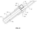
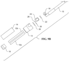
- At least two optical conduits can be positioned (at least partially or entirely) within a cover sleeve 14.
- a hub 13 can include a first end with a radially outwardly receptacle to receive at least a portion of the cover sleeve 14, and one or more radially inwardly receptacles to receive at least a portion of each optical conduit 12a, 12b.
- a photomultiplier (PMT) light sensor or light detector 16 can be attached to the hub 14.
- a light feed, fiber bundle or input light guide 15 can operatively connect the optical conduits 12a, 12b to a light source and/or a measurement device.
- an opposing second end of the hub 13 can include a receptacle to receive at least a portion of the light feed 15.
- thelight feed 15 can be removably attached to the hub 13.
- An end fitting 18 with a raised lip that surrounds a portion of the optical conduits 12a, 12b can attach to the cover sleeve 14. At least a portion of the raised lip of the end fitting 18 can contact the subject's skin 20 during use or testing.
- a light filter 22, a stop capsule 24, two or more light seals 26, each optionally in the form of an O-ring, and a molded light gasket 28 can be positioned within the hub 13 between the light feed 15 and the optical conduits 12a, 12b.
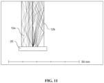
- Fig. 12 shows an internal skin diffusion model according to one embodiment of the present disclosure.
- the bottom area or rectangle is representative of skin that services as bulk scatter material with 0.01 mm mean path length.
- light in source rod enters from the upper left in Fig. 12 , enters the skin and is diffused internally. Remitted light is picked up along line on mating rod edge. Remitted light is captured in rod 12b and transmitted to one or more photomultiplier (PMT) sensors.
- PMT photomultiplier
- each remission conduit 112b can be positioned between two emission conduits 112a, and a variety of different options exist for the numbers of each conduit 112a, 112b.
- four emission conduits 112a e.g., "source slivers”
- three remission conduits 112b are used.
- five emission conduits 112a and four remission conduits 112b are used.
- the device can include three emission conduits 112a and two remission conduits 112b.
- a homogenizer 130 such as a homogenizer rod, can be attached or operatively connected to a first or proximal end of each of the plurality of conduits 112a, 112b.
- An input light guide 115 can be attached or operatively connected to an end of the homogenizer 130 opposite the plurality of conduits 112a, 112b.
- one or a plurality of PMT light detectors 116 can be used.
- four light detectors 116 can be attached to or operatively connected to the first or proximal end of the remission conduits 112b, or a single PMT detector 116 can be operatively connected to the first or proximal end of the remission conduits 112b.
- One or more filters 132 can be positioned between each corresponding light detector 116 and remission conduit 112b.
- One or a plurality of moisture seals 134 can be located at or near a second or distal end of each of the plurality of conduits 112a, 112b. The second or distal end of each of the plurality of conduits 112a, 112b is the output/input face 136 of the device.
- Test Data Eight sunscreens of known SPF value were tested using one embodiment of the polychromatic DRS system described herein. Determination of both the SPF and the UVA-PF can be derived solely from the polychromatic DRS UVA-PF measurement, and a separate in vitro thin film spectroscopic scan. The amount of UVA light remitted from the skin was measured with the polychromatic DRS device. The sensitivity of the photomultiplier was adjusted at each site by adjusting the high voltage to achieve as high a signal that is possibleyet below the saturation level of the photomultiplier. Remitted intensity at each of three sites for each of the eight sunscreens was recorded. The sunscreens were then applied at a density of 2 mg/cm 2 (standard dosage rate) and allowed to dry for 15 minutes. The remitted light was measured in triplicate and recorded at each of the sunscreen sites.
- the in vitro absorbance of each of the sunscreens was measured on polymethylmethacrylate (PMMA) plates before and after UV irradiation (to account for nonphotostable sunscreen behavior - see Ruvolo et al. discussed above).
- PMMA polymethylmethacrylate
- the absorbance after the UV exposure was adjusted according to the magnitude of the UVA-PF to match the polychromatic UVA-PF DRS measurement. This resulting adjusted absorbance spectrum was then used to calculate the predicted SPF value of each of the sunscreens.
- the Individual Typology Angle (ITA) angle of the skin was measured with a Minolta Chromameter at each sunscreen application site (test site). Each test site was marked with a surgical marker having an area of 3 ⁇ 10 cm 2 .
- the device according to the presently disclosed technology was placed on the surface of the skin at each treatment site, and the High Voltage setting was adjusted to yield a reading of 12V (just below saturation at 14V). Three measurements were then made within each test site using the device and recorded for the baseline measurements.
- Sunscreen Application The sunscreen treatment sites were randomized for each subject and given a unique treatment code. Sunscreens were applied at 2mg/cm 2 to the test area by "dotting" the area with sunscreen formulation, and gently spreading the sunscreen over the entire test area for approximately 20 seconds. A minimum of 15 minutes elapsed before initiating further measurements.
- PPD Persistent Pigment Darkening
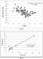
- Fig. 18 shows the relationship between unprotected MED values for sunscreen test subjects and their ITA° as published by others.
- R 2 is the first order linear fit of the indicated line equation.
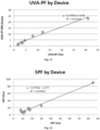
- UVA-PF Evaluations Using the same scaled post-UV exposure absorbance curves to estimate SPF values, combined with the PPD action spectra and clinical UVA simulator spectrum, UVA-PF values were calculated. Determinations were again made using the two spectrophotometer devices. The results are shown in Table 4 below (as well as in Fig. 20 ):
- Data obtained from this device can be used to calculate the degree of protection provided by sunscreen compositions. These calculations can be performed in a variety of known ways. For example, E. Ruvolo et al, New noninvasive approach assessing in vivo sun protection factor (SPF) using diffuse reflectance spectroscopy (DRS) and in vitro transmission, Photodermatol Photoimmunol Photomed 2014 Vol. 30;4, pp. 202-211 .
- SPF sun protection factor
- DRS diffuse reflectance spectroscopy
- Sun protection factors may also be calculated by constructing the photodetector in such a way that its responsiveness to remitted light mimics the biological responsiveness of skin to the various portions or wavelengths of light that are of interest. This eliminates the need to conduct measurements of the amount of remitted light at each of the various portions or wavelengths of light, weight them according to the biological responsiveness of skin to the various portions or wavelengths of light, and then execute calculations based on that weighting.
- reflectance spectroscopic measurements of SPF have accounted for responsiveness of skin to the various portions or wavelengths of light to which it can be exposed by passing remitted light through a device (e.g. a diffraction grating or monochromator) that breaks the remitted light into a spectrum. Measurements are then made of the amount of remitted light in each of the various portions or wavelengths of remitted light. These measurements are then weighted in accordance with the skin responsiveness data mentioned above, and the SPF is then calculated. This method, while workable, requires a great deal of calculation to accomplish the weighting.
- a device e.g. a diffraction grating or monochromator
- a spectral analysis and spectral weighting according to the biological responsiveness of skin to light is different for each of the various portions or wavelengths of light to which it can be exposed can be eliminated, along with the costly, noise-producing hardware required for that weighting.
- the photodetector that receives the remitted light is modified so that its sensitivity to remitted light in the range of interest approximates or matches the biological responsiveness of skin to that light. That is to say, the sensitivity of the photodetector over this range is made to approximate or match the responsiveness or sensitivity curve of skin. This may be done so as to match the sensitivity or responsiveness curve with respect to erythema, pigmentation, or a combination of them.
- the SPF can be calculated using conventional computations.
- Photodetectors can be configured for use in this aspect of the presently disclosed technology in a variety of ways.
- a filter or set of filters that in combination that matches the skin responsiveness curve can be incorporated into or used in conjunction with the photodetector cell, as illustrated in Figs. 8-9B .
- An example of such a filter material is the UG11, manufactured by the Schott Group, which diminishes the responsivity to longer wavelength UV without affecting mid-UV or short UV regions of the spectrum.
- Interference filters can be constructed that selectively tune to pass certain wavelength regions, and reject (absorb) other regions to shape the response spectrum of the system (filters + photocell).
- Fluorescent materials that respond to UV radiation in a certain region of the UV can also be used to modify thespectral response of the system (such as MgWO 4 for erythema response spectrum) as described by Berger in The sunburning ultraviolet meter: Design and performance. Photochem. Photobiol. 1976: 24; 587-593 .
- the responsiveness of the photodetector cell's material can be selected to match the skin responsiveness curve, or the responsiveness of the photodetector cell can be electronically tuned to achieve this result.
- the combination of the photocell response spectrum and the modifying filters or intervening optical spectrum modifiers together as a unit can thus be made to respond with a signal similar to the way skin would respond to the incident light source.
- the light source chosen for the measurement of the UV protectiveness of the sunscreen using the inventive device can have the same spectral distribution as the source that is used in clinical testing for the UVA-PF measurements.
- the system can reproduce the UVA-PF of the sunscreen being tested by replicating the clinical test conditions with the same incident light spectrum, and using a detection system for the remitted light that responds with the same spectral response sensitivity as does human skin.
- a simple two measurement observation sequence provides the UVA-PF of the sunscreen without requiring a spectral breakdown of the light into its individual wavelength components (monochromators or "spectral analyzer") in order to weight with skin response spectra and to determine a UVA-PF value.
Landscapes
- Physics & Mathematics (AREA)
- Spectroscopy & Molecular Physics (AREA)
- General Physics & Mathematics (AREA)
- Health & Medical Sciences (AREA)
- Life Sciences & Earth Sciences (AREA)
- General Health & Medical Sciences (AREA)
- Veterinary Medicine (AREA)
- Public Health (AREA)
- Animal Behavior & Ethology (AREA)
- Optics & Photonics (AREA)
- Birds (AREA)
- Epidemiology (AREA)
- Chemical & Material Sciences (AREA)
- Emergency Medicine (AREA)
- Biochemistry (AREA)
- Immunology (AREA)
- Analytical Chemistry (AREA)
- Pathology (AREA)
- Inorganic Chemistry (AREA)
- Dermatology (AREA)
- Engineering & Computer Science (AREA)
- Plasma & Fusion (AREA)
- Mathematical Physics (AREA)
- Investigating Or Analysing Materials By Optical Means (AREA)
- Measurement Of The Respiration, Hearing Ability, Form, And Blood Characteristics Of Living Organisms (AREA)
Applications Claiming Priority (4)
| Application Number | Priority Date | Filing Date | Title |
|---|---|---|---|
| US201762510598P | 2017-05-24 | 2017-05-24 | |
| US201762540643P | 2017-08-03 | 2017-08-03 | |
| PCT/US2018/031320 WO2018217432A1 (fr) | 2017-05-24 | 2018-05-07 | Système, appareil et procédé de mesure polychrome in situ de propriétés optiques d'écran solaire appliqué par voie topique |
| EP18806530.4A EP3600566B1 (fr) | 2017-05-24 | 2018-05-07 | Système, appareil et procédé de mesure polychrome in situ de propriétés optiques d'écran solaire appliqué par voie topique |
Related Parent Applications (2)
| Application Number | Title | Priority Date | Filing Date |
|---|---|---|---|
| EP18806530.4A Division EP3600566B1 (fr) | 2017-05-24 | 2018-05-07 | Système, appareil et procédé de mesure polychrome in situ de propriétés optiques d'écran solaire appliqué par voie topique |
| EP18806530.4A Division-Into EP3600566B1 (fr) | 2017-05-24 | 2018-05-07 | Système, appareil et procédé de mesure polychrome in situ de propriétés optiques d'écran solaire appliqué par voie topique |
Publications (2)
| Publication Number | Publication Date |
|---|---|
| EP4235121A2 true EP4235121A2 (fr) | 2023-08-30 |
| EP4235121A3 EP4235121A3 (fr) | 2023-09-20 |
Family
ID=64396779
Family Applications (2)
| Application Number | Title | Priority Date | Filing Date |
|---|---|---|---|
| EP23178567.6A Pending EP4235121A3 (fr) | 2017-05-24 | 2018-05-07 | Système, appareil et procédé de mesure polychrome in situ de propriétés optiques d'écran solaire appliqué par voie topique |
| EP18806530.4A Active EP3600566B1 (fr) | 2017-05-24 | 2018-05-07 | Système, appareil et procédé de mesure polychrome in situ de propriétés optiques d'écran solaire appliqué par voie topique |
Family Applications After (1)
| Application Number | Title | Priority Date | Filing Date |
|---|---|---|---|
| EP18806530.4A Active EP3600566B1 (fr) | 2017-05-24 | 2018-05-07 | Système, appareil et procédé de mesure polychrome in situ de propriétés optiques d'écran solaire appliqué par voie topique |
Country Status (4)
| Country | Link |
|---|---|
| US (3) | US11022485B2 (fr) |
| EP (2) | EP4235121A3 (fr) |
| KR (2) | KR102634202B1 (fr) |
| WO (1) | WO2018217432A1 (fr) |
Families Citing this family (6)
| Publication number | Priority date | Publication date | Assignee | Title |
|---|---|---|---|---|
| EP3790632A4 (fr) | 2018-05-08 | 2022-03-09 | Solar Light Company, Inc. | Spectroscopie de réflectance diffuse in vitro |
| KR102082050B1 (ko) * | 2018-07-16 | 2020-02-27 | 국민대학교산학협력단 | 일주기 조도 측정 장치 |
| WO2021007420A1 (fr) * | 2019-07-09 | 2021-01-14 | Henry Ford Health System | Système et procédé de test des effets de la lumière ultraviolette et visible sur la peau |
| DE102020103490A1 (de) | 2020-02-11 | 2021-08-12 | Courage + Khazaka Electronic Gmbh | Messsystem und messverfahren |
| DE102020119026A1 (de) | 2020-07-17 | 2022-01-20 | Courage + Khazaka Electronic Gmbh | Messsystem und Messverfahren |
| CA3229844A1 (fr) * | 2021-08-27 | 2023-03-02 | Matthew James CLEMENTE | Systemes et procedes pour determiner et communiquer des niveaux de bilirubine et d'autres substances sous-cutanees |
Family Cites Families (13)
| Publication number | Priority date | Publication date | Assignee | Title |
|---|---|---|---|---|
| DE1249559B (fr) * | 1962-11-19 | |||
| JPH0239145U (fr) * | 1988-09-09 | 1990-03-15 | ||
| US5640957A (en) * | 1993-09-29 | 1997-06-24 | Instruments Sa, Inc. | Ultraviolet radiation protection evaluator |
| IL109181A (en) * | 1994-03-31 | 1997-04-15 | Israel Atomic Energy Comm | Fiber optic reflectance probe |
| US5625459A (en) * | 1995-03-03 | 1997-04-29 | Galileo Electro-Optics Corporation | Diffuse reflectance probe |
| US6995835B2 (en) * | 1997-03-03 | 2006-02-07 | Nir Diagnostics Inc. | Method and apparatus for measuring analytes in blood bags |
| US6261006B1 (en) * | 1999-09-24 | 2001-07-17 | Amphenol Corporation | Environmental sealing for fiber optic cable assemblies |
| KR20030086766A (ko) * | 2002-05-07 | 2003-11-12 | 김종기 | 피부조직 확산 반사광 스펙트름 분석기를 이용한 화장품제재 혹은 의료용 약품의 in vivo 피부흡수 및 피부내 확산 특성 진단기. |
| US7657147B2 (en) * | 2006-03-02 | 2010-02-02 | Solar Light Company, Inc. | Sunlight simulator apparatus |
| US7888001B2 (en) * | 2006-07-11 | 2011-02-15 | Stc.Unm | System and methods for measuring a skin protection factor |
| WO2013132914A1 (fr) * | 2012-03-05 | 2013-09-12 | 大塚製薬株式会社 | Composition d'écran solaire |
| DE202014010964U1 (de) * | 2014-03-07 | 2017-03-10 | Laser- Und Medizin-Technologie Gmbh, Berlin | Sensorvorrichtung für ortsauflösende Erfassung von Zielsubstanzen |
| JP2018533013A (ja) * | 2015-10-20 | 2018-11-08 | カレッジ・アンド・カザカ・エレクトロニック・ゲゼルシャフト・ミット・ベシュレンクテル・ハフツング | 日焼け止め剤又は他の放射線防護剤のサンプロテクションファクタの光学的確認 |
-
2018
- 2018-05-07 EP EP23178567.6A patent/EP4235121A3/fr active Pending
- 2018-05-07 KR KR1020227018664A patent/KR102634202B1/ko active Active
- 2018-05-07 KR KR1020197037544A patent/KR102406858B1/ko active Active
- 2018-05-07 WO PCT/US2018/031320 patent/WO2018217432A1/fr not_active Ceased
- 2018-05-07 EP EP18806530.4A patent/EP3600566B1/fr active Active
-
2019
- 2019-09-10 US US16/565,602 patent/US11022485B2/en active Active
-
2021
- 2021-05-14 US US17/302,915 patent/US11397107B2/en active Active
-
2022
- 2022-06-17 US US17/807,458 patent/US11874164B2/en active Active
Non-Patent Citations (7)
| Title |
|---|
| ANDERS, A. ET AL.: "Action Spectrum For Erythema In Humans Investigated With Dye Lasers", PHOTOCHEMISTRY AND PHOTOBIOLOGY, vol. 61, no. 2, 1995, pages 200 - 205 |
| BERGER: "The sunburning ultraviolet meter: Design and performance", PHOTOCHEM. PHOTOBIOL., vol. 24, 1976, pages 587 - 593 |
| E. RUVOLO ET AL.: "New noninvasive approach assessing in vivo sun protection factor (SPF) using diffuse reflectance spectroscopy (DRS) and in vitro transmission", PHOTODERMATOL PHOTOIMMUNOL PHOTOMED, vol. 30, no. 4, 2014, pages 202 - 211, XP055339170, DOI: 10.1111/phpp.12105 |
| GANGE, R.W. ET AL.: "The biological effects of UVA radiation", 1986, PRAEGER PUBLISHERS, article "Action spectra for Cutaneous Responses to Ultraviolet Radiation", pages: 57 - 65 |
| MATTS PALARD VBROWN MWFERRERO LGERS-BALAG HISSACHAR NMOYAL DWOLBER R: "The COLIPA in vitro UVA method: a standard and reproducible measure of sunscreen UVA protection", INT. J. COSM. SCI., vol. 32, no. 1, 2010, pages 35 - 46, XP007911165, DOI: 10.1111/j.1468-2494.2009.00542.x |
| MOYAL, D. ET AL.: "Determination Of UVA Protection Factors Using The Persistent Pigment Darkening (PPD) As The End Point", PHOTODERMATOL PHOTOIMMUNOL PHOTOMED, vol. 16, 2000, pages 245 - 249 |
| RUVOLO EKOLLIAS NCOLE C.: "New non-invasive approach assessing in vivo sun protection factor (SPF) using diffuse reflectance spectroscopy and in vitro transmission", PHOTODERMATOLOGY, PHOTOIMMUNOLOGY & PHOTOMEDICINE, vol. 30, no. 4, 2014, pages 202 - 211 |
Also Published As
| Publication number | Publication date |
|---|---|
| US11022485B2 (en) | 2021-06-01 |
| KR20220080026A (ko) | 2022-06-14 |
| KR20200010394A (ko) | 2020-01-30 |
| US11874164B2 (en) | 2024-01-16 |
| US20210270668A1 (en) | 2021-09-02 |
| US20220316942A1 (en) | 2022-10-06 |
| EP4235121A3 (fr) | 2023-09-20 |
| US11397107B2 (en) | 2022-07-26 |
| EP3600566A4 (fr) | 2021-04-21 |
| KR102634202B1 (ko) | 2024-02-08 |
| EP3600566A1 (fr) | 2020-02-05 |
| KR102406858B1 (ko) | 2022-06-13 |
| EP3600566B1 (fr) | 2023-09-06 |
| US20200018640A1 (en) | 2020-01-16 |
| WO2018217432A1 (fr) | 2018-11-29 |
Similar Documents
| Publication | Publication Date | Title |
|---|---|---|
| US11874164B2 (en) | System, apparatus and method for in situ polychromatic measurement of optical properties of topically applied sunscreen | |
| EP2071306B1 (fr) | Dispositif de détection de rayon ultraviolet et dispositif permettant d'évaluer un effet protecteur contre un rayon ultraviolet | |
| US11137347B2 (en) | Optically ascertaining the sun protection factor of sunscreens or other radiation protection agents | |
| US6678541B1 (en) | Optical fiber probe and methods for measuring optical properties | |
| US9909992B2 (en) | Optical spectrometer with matched étendue | |
| US5640957A (en) | Ultraviolet radiation protection evaluator | |
| US20170261425A1 (en) | Optical evaluation of skin type and condition | |
| CN102058393A (zh) | 基于反射光谱测量的皮肤生理参数与光学特性参数的测量方法和系统 | |
| NL8004712A (nl) | Werkwijze en inrichting voor het op aanwezigheid van caries onderzoeken van een gebit. | |
| Bielfeldt et al. | Multicenter methodology comparison of the FDA and ISO standard for measurement of in vitro UVA protection of sunscreen products | |
| Reble et al. | Evaluation of detection distance‐dependent reflectance spectroscopy for the determination of the sun protection factor using pig ear skin | |
| Fajuyigbe et al. | Diffuse reflectance spectroscopy as a reliable means of comparing ultraviolet radiation‐induced erythema in extreme skin colors | |
| Ruvolo et al. | Multi‐laboratory study of hybrid diffuse reflectance spectroscopy to assess sunscreen SPF and UVA‐PFs | |
| Pearse et al. | Portable erythema meter and its application to use in human skin | |
| Coleman et al. | Clinical ultraviolet dosimetry with a CCD monochromator array spectroradiometer | |
| Ruvolo et al. | Performance of hybrid diffuse reflectance spectroscopy (HDRS‐ISO 23698) methodology for assessment of sunscreen protection in the ALT‐SPF Consortium validation study | |
| Ruvolo Jr et al. | Diffuse reflectance spectroscopy for ultraviolet A protection factor measurement: correlation studies between in vitro and in vivo measurements | |
| JP7239400B2 (ja) | 皮膚抗酸化能の判定方法 | |
| Kobylinski et al. | Noninvasive measurement of the 308 nm LED‐based UVB protection factor of sunscreens | |
| Osman et al. | Visible Spectroscopy in EBT3 Solar Ultraviolet Dosimeter | |
| US11293857B2 (en) | Vitro diffuse reflectance spectroscopy | |
| Sayre et al. | In vitro sunscreen transmittance measurement with concomitant evaluation of photostability: evolution of a method |
Legal Events
| Date | Code | Title | Description |
|---|---|---|---|
| PUAI | Public reference made under article 153(3) epc to a published international application that has entered the european phase |
Free format text: ORIGINAL CODE: 0009012 |
|
| STAA | Information on the status of an ep patent application or granted ep patent |
Free format text: STATUS: THE APPLICATION HAS BEEN PUBLISHED |
|
| REG | Reference to a national code |
Ref country code: DE Ref legal event code: R079 Free format text: PREVIOUS MAIN CLASS: G01J0003020000 Ipc: A61Q0017040000 |
|
| PUAL | Search report despatched |
Free format text: ORIGINAL CODE: 0009013 |
|
| AC | Divisional application: reference to earlier application |
Ref document number: 3600566 Country of ref document: EP Kind code of ref document: P |
|
| AK | Designated contracting states |
Kind code of ref document: A2 Designated state(s): AL AT BE BG CH CY CZ DE DK EE ES FI FR GB GR HR HU IE IS IT LI LT LU LV MC MK MT NL NO PL PT RO RS SE SI SK SM TR |
|
| AK | Designated contracting states |
Kind code of ref document: A3 Designated state(s): AL AT BE BG CH CY CZ DE DK EE ES FI FR GB GR HR HU IE IS IT LI LT LU LV MC MK MT NL NO PL PT RO RS SE SI SK SM TR |
|
| RIC1 | Information provided on ipc code assigned before grant |
Ipc: G01J 3/02 20060101ALI20230816BHEP Ipc: G01J 1/42 20060101ALI20230816BHEP Ipc: G01J 1/04 20060101ALI20230816BHEP Ipc: G01J 1/02 20060101ALI20230816BHEP Ipc: G02B 6/255 20060101ALI20230816BHEP Ipc: G02B 6/08 20060101ALI20230816BHEP Ipc: G02B 6/06 20060101ALI20230816BHEP Ipc: G01J 3/42 20060101ALI20230816BHEP Ipc: A61Q 17/04 20060101AFI20230816BHEP |
|
| STAA | Information on the status of an ep patent application or granted ep patent |
Free format text: STATUS: REQUEST FOR EXAMINATION WAS MADE |
|
| 17P | Request for examination filed |
Effective date: 20240318 |
|
| RBV | Designated contracting states (corrected) |
Designated state(s): AL AT BE BG CH CY CZ DE DK EE ES FI FR GB GR HR HU IE IS IT LI LT LU LV MC MK MT NL NO PL PT RO RS SE SI SK SM TR |
|
| STAA | Information on the status of an ep patent application or granted ep patent |
Free format text: STATUS: EXAMINATION IS IN PROGRESS |
|
| 17Q | First examination report despatched |
Effective date: 20250620 |