EP4235255A2 - Dispositif optique et procédé d'imagerie d'un échantillon - Google Patents
Dispositif optique et procédé d'imagerie d'un échantillon Download PDFInfo
- Publication number
- EP4235255A2 EP4235255A2 EP23171141.7A EP23171141A EP4235255A2 EP 4235255 A2 EP4235255 A2 EP 4235255A2 EP 23171141 A EP23171141 A EP 23171141A EP 4235255 A2 EP4235255 A2 EP 4235255A2
- Authority
- EP
- European Patent Office
- Prior art keywords
- sample
- objective lens
- radiation
- illumination beam
- mirror
- Prior art date
- Legal status (The legal status is an assumption and is not a legal conclusion. Google has not performed a legal analysis and makes no representation as to the accuracy of the status listed.)
- Granted
Links
Images




Classifications
-
- G—PHYSICS
- G02—OPTICS
- G02B—OPTICAL ELEMENTS, SYSTEMS OR APPARATUS
- G02B21/00—Microscopes
- G02B21/18—Arrangements with more than one light path, e.g. for comparing two specimens
-
- G—PHYSICS
- G02—OPTICS
- G02B—OPTICAL ELEMENTS, SYSTEMS OR APPARATUS
- G02B21/00—Microscopes
- G02B21/06—Means for illuminating specimens
-
- G—PHYSICS
- G02—OPTICS
- G02B—OPTICAL ELEMENTS, SYSTEMS OR APPARATUS
- G02B21/00—Microscopes
- G02B21/16—Microscopes adapted for ultraviolet illumination ; Fluorescence microscopes
-
- G—PHYSICS
- G02—OPTICS
- G02B—OPTICAL ELEMENTS, SYSTEMS OR APPARATUS
- G02B21/00—Microscopes
- G02B21/36—Microscopes arranged for photographic purposes or projection purposes or digital imaging or video purposes including associated control and data processing arrangements
- G02B21/361—Optical details, e.g. image relay to the camera or image sensor
-
- G—PHYSICS
- G02—OPTICS
- G02B—OPTICAL ELEMENTS, SYSTEMS OR APPARATUS
- G02B21/00—Microscopes
- G02B21/36—Microscopes arranged for photographic purposes or projection purposes or digital imaging or video purposes including associated control and data processing arrangements
- G02B21/365—Control or image processing arrangements for digital or video microscopes
- G02B21/367—Control or image processing arrangements for digital or video microscopes providing an output produced by processing a plurality of individual source images, e.g. image tiling, montage, composite images, depth sectioning, image comparison
-
- H—ELECTRICITY
- H04—ELECTRIC COMMUNICATION TECHNIQUE
- H04N—PICTORIAL COMMUNICATION, e.g. TELEVISION
- H04N13/00—Stereoscopic video systems; Multi-view video systems; Details thereof
- H04N13/10—Processing, recording or transmission of stereoscopic or multi-view image signals
- H04N13/106—Processing image signals
-
- H—ELECTRICITY
- H04—ELECTRIC COMMUNICATION TECHNIQUE
- H04N—PICTORIAL COMMUNICATION, e.g. TELEVISION
- H04N13/00—Stereoscopic video systems; Multi-view video systems; Details thereof
- H04N13/20—Image signal generators
- H04N13/204—Image signal generators using stereoscopic image cameras
- H04N13/207—Image signal generators using stereoscopic image cameras using a single two-dimensional [2D] image sensor
-
- H—ELECTRICITY
- H04—ELECTRIC COMMUNICATION TECHNIQUE
- H04N—PICTORIAL COMMUNICATION, e.g. TELEVISION
- H04N13/00—Stereoscopic video systems; Multi-view video systems; Details thereof
- H04N13/20—Image signal generators
- H04N13/282—Image signal generators for generating image signals corresponding to three or more geometrical viewpoints, e.g. multi-view systems
-
- H—ELECTRICITY
- H04—ELECTRIC COMMUNICATION TECHNIQUE
- H04N—PICTORIAL COMMUNICATION, e.g. TELEVISION
- H04N2213/00—Details of stereoscopic systems
- H04N2213/001—Constructional or mechanical details
Definitions
- the invention relates to an optical arrangement and a method for imaging a sample using at least two illumination beams.
- a microscope is a scientific instrument that is used for the visualization of objects, which can be either small cells or have details that are too small to be resolved by the naked eye.
- optical microscope which uses light in a system of lenses to magnify images of the samples.
- the image from the optical microscope can be either viewed through an eyepiece or, more commonly nowadays, captured by a light-sensitive camera sensor to generate a so-called micrograph.
- sensors available to catch the images.
- Non-limiting examples are charge-coupled devices (CCD) and scientific complementary metal-oxide semiconductor (sCMOS) based technologies, which are widely used. These sensors allow the capture and storage of digital images to the computer. Typically there is a subsequent processing of these images in the computer to obtain the desired information.
- CCD charge-coupled devices
- sCMOS scientific complementary metal-oxide semiconductor
- the illumination sources as used in optical microscopes have been developed over the years and wide varieties of illumination sources are currently available, which can emit light or other type of radiation at different wavelengths.
- Optical filters can be placed between the illumination source and the sample to be imaged in order to restrict the wavelength of the radiation illuminating the sample.
- Modern biological microscopy uses fluorescent probes for imaging specific structures within a cell as the sample.
- the sample in fluorescent microscopy is illuminated through one or more objective lenses with a narrow set of light wavelengths. These narrow set of light wavelengths interact with fluorophores in the sample, which then emit light of a different wavelength. This emitted fluorescent light is detected in a detector and is used to construct the image of the sample.
- the use of multiple images enables a 3-dimensional reconstruction of the sample to be made.
- This 3-D reconstruction can be done by generating images at different positions on the sample, as the sample moves relatively to one or more objective lens.
- several detectors may be required. These detectors are quite expensive and a microscope designer will wish to reduce the number of detectors.
- the use of a single detector, which is moved during the imaging process, can be disadvantageous in that the movement of the detector itself can slightly effect the position of the sample, due to vibrations. Alternately the sample itself may move for other reasons whilst the detector is being placed into another position. This movement of the detector requires a precise and fast movement of a part of hardware, which is comparatively massive and in turn leads to further increase in development costs and/or in extra parts of equipment.
- European patent EP 1 019 769 (Carl Zeiss, Jena ) teaches a compact confocal feature microscope, which can be used as a microscope with a single objective lens or with multiple objective lenses.
- the microscope has separate directions of illumination and detection.
- the direction of detection in the objective lens is aligned inclined at a set angle in relation to the direction of illumination.
- An optical arrangement for imaging a sample comprises at least one first objective lens and at least one second objective lens, at least one illumination source for producing an illumination beam, a detector for imaging radiation from the sample, and at least one selectable mirror.
- the selectable mirror is adapted to reflecting the radiation from one of the first objective lens or the second objective lens into the detector. The position of the selected mirror is dependent on the illumination beam at the other one of the first objective lens of the second objective lens. The use of the selected mirror enables a single detector to be used to image the sample from multiple sides and thus save on the detectors.
- the at least one selectable mirror is translatable or rotatable.
- the selectable mirror can be double-sided.
- At least two further selectable mirrors are present and the reflected radiation can be directed into one of the at least two further selectable mirrors.
- An optical filter can be inserted in the path of the illumination beam or the path of the radiation to select only certain wavelengths of light.
- a third objective lens can be used to collect the radiation from the sample.
- a method for imaging a sample comprises illuminating the sample using a first illumination beam, detecting, at a stationary detector in a stationary position, first radiation from the sample, processing the first radiation to obtain a first data set, illuminating the sample using a second illumination beam at an angle to the first illumination beam, detecting, at the stationary detector in the stationary position, second radiation from the sample, processing the second radiation to obtain a second data set, and combining the first data set and the second data set to produce an image of the sample.
- Fig. 1 shows an overview of an optical arrangement 10 of this disclosure.
- the optical arrangement 10 has a first objective lens 30 and a second objective lens 40. Both the first objective lens 30 and the second objective lens 40 are able to image a sample 20 and/or direct an illumination beam 60 and 60' onto the sample 20.
- the optical arrangement 10 shown in Fig. 1 has two objective lenses 30 and 40, but this is not limiting of the invention. It would be possible to have an optical arrangement with a larger number of objective lenses.
- the optical arrangement 10 has an illumination source 50 that produces the illumination beam 60.
- the optical arrangement 10 has also a detector 70 that is able to detect radiation 80 reflected or fluoresced from the sample 20.
- the sample 20 is typically a biological sample.
- the sample 20 is to be imaged in three dimensions. It is known that a minimum of one view is required to create a 3D stack of images. At least two views are required in order to make a multi-view image of the sample 20 in the optical arrangement of Fig. 1a.
- the views can then be stored in a memory 110 as a first data set 120 and a second data set 130 and combined in a processor 100 in order to construct a multidimensional dataset.
- This multidimensional dataset can, for example, be used to create a 3D multi-view image of the sample 20.
- Both of the first objective lens 30 and the second objective lens 40 can be used to illuminate the sample 20 and/or gather radiation fluoresced or reflected from the sample 20.
- a black box 95 as is illustrated in Fig. 1 .
- the black box 95 outlines the manner in which the illumination beam 60 from the illumination beam source 50 can be directed either to the first objective lens 30 or, for example by use of mirrors, as an illumination beam 60' to the second objective lens 40.
- the black box 95 also shows that radiation from the sample 20 can be directed either through the first objective lens 30 as a radiation beam 80' or from the second objective lens 40 and thence to the detector 70 as a radiation beam 80.
- the optical arrangement 10 illustrated in Fig. 1 is therefore able to create at least two images of the sample 20 from different angles in order to allow the construction of a 3D image of the sample 20. This principle can be implemented using different mirror arrangements as described below.
- Figs. 2a and 2b show a first aspect of the optical arrangement 10 in which the illumination source 50 is located to one side of the detector 70.
- the illumination source 50 is shown to the left hand side of the single detector 70 and produces an illumination beam 60 arriving at the first objective lens 30 from which the illumination beam 60 is projected onto the sample 20.
- Radiation from the sample 20 is imaged through the second objective lens 40 and strikes the right mirror 90a on the right hand side from which the radiation 80 is reflected to a central mirror 90c and thence into the detector 70.
- Fig. 2a includes further a left mirror 90b. It will be seen from Fig. 2a that the left hand mirror 90b does not interrupt the passage of the illumination beam 60 from the illumination source 50 on the left hand side.
- the optical arrangement 10 of Fig. 2a can be compared with the optical arrangement 10 shown in Fig. 2b .
- the optical arrangement 10 of Fig. 2b comprises the same elements with the same numbers as shown in Fig. 2a.
- Fig. 2b shows, however, a further illumination source 50' on the right hand side which produces an illumination beam 60' entering the second objective lens 40. It will be seen that the right hand mirror 90a has been moved out of the path of the illumination beam 60', so that this right hand mirror 90a does not interrupt the passage of the illumination beam 60'.
- the radiation 80' from the sample 20 passes through the first objective lens 30 and is reflected by the left-hand side mirror 90b onto the central mirror 90c and thence into the detector 70.
- the right hand mirror 90a, the left hand mirror 90b and the central mirror 90c have in Fig. 2b been shifted to the right compared to the equivalent positions in Fig 2a in order to allow the illumination beams 60, 60' and the radiation 80 and 80' to be reflected differently.
- This is indicated figuratively by arrow 92.
- the movement of the mirrors 90a, 90b, 90c, as indicated by the arrow 92 and can be easily implemented, for example on a sliding track.
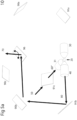
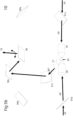
- Fig. 3a and 3b show a second aspect of the invention in which a single central mirror 90c is moved up and down, as indicated by an arrow 94.
- the optical arrangement 10 of Figs. 3a and 3b has otherwise the same elements as the optical arrangement shown on Figs. 2a and 2b .
- the optical arrangement 10 has, however, a single detector 70 on the left hand side and a single illumination source 50 on the right hand side.
- Fig. 3a shows a lower position of the central mirror 90c in which the illumination source 50 produces the illumination beam 60' reflected by the central mirror 90c onto the right hand mirror 90a and thence into the second objective lens 40, thereby illuminating the sample 20.
- Radiation from the sample 20 is collected by the first objective lens 30 and reflected by the left hand mirror 90b onto the central mirror 90c and thence into the detector 70.
- the central mirror 90c is moved to make way for the illumination beam 60 and the radiation 80.
- the illumination beam 60 is produced by the illumination source 50 and is reflected by the left hand mirror 90b onto the sample 20 through the first objective lens 30.
- the radiation from the sample 20 is imaged through the second objective lens 40 and is reflected by the right hand mirror 90a into the detector 70.
- two images of the sample 20 can be produced.
- the method of the invention is shown in Fig. 4 in which an illumination beam 50 is produced in step 200 from the illumination source 50 or 50'. It will be understood from Figs. 2a and 2b as well as Figs. 3a and 3b and Figs. 5a-c that there may be a single one of the illumination source 50 (as shown in Figs. 3a and 3b and Figs5.a-c ) or two illumination sources 50 and 50' as shown in Figs. 2a and 2b . There may be more illumination sources, as is the case of having more than two objectives as depicted in Figs.5 a-c .
- the illumination beam 50 is directed in step 205 to the sample 20 and reflected in step 206 from the sample 20.
- the detection of the radiation 80 is carried out in step 210 in the detector 70.
- the detector 70 can be, for example, a charge coupled device or any other detection instrument.
- a first image produced from the illumination beam is processed in step 220 in a processor 100 and stored in a memory 110 as a first data set 120.
- a second illumination beam 80 is created in step 230 and illuminates the sample 20 from a different direction in step 235.
- the second illumination beam is reflected from the sample 220 in step 238 and is detected in the same detector 70.
- the image is then processed in the processor in step 250 and stored in the memory 110 as a second data set 130.
- the first data set 120 and the second data set 130 forming the two images can be combined in step 260 in the processor 100 to produce the multi-view 3D image of the sample 20.
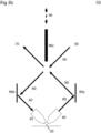
- Figs. 5a-c shows a third aspect of this disclosure using more than two objective lenses.
- the illumination beam 60, 60' or 60" is produced from the illumination source 50 and passes through one of a plurality of optical selectors 91a, 91b or 91c.
- the optical selectors 91a, 91b or 91c may be optical filters allowing passage of certain wavelengths, movable mirrors, moving shutters, or another possible optical selector device.
- Figs. 5a-c illustrates particular cases in which an optical filter that allows certain wavelengths to pass through is utilized for the optical selectors 91a, 91b, or 91c.
- the illumination beam 60" of the aspect depicted in Fig. 5a passes through the optical filter 91c.
- the illumination beam 60" passes through a third objective lens 31 and illuminates the sample 20.
- the radiation 80 coming from sample 20 is collected by the second objective lens 40, reflects on the optical selector 91b, and reflects on the mirror 90b towards a radiation selector 96.
- the radiation selector 96 is shown as a rotating mirror in Figs. 5a-c .
- the radiation selector 96 can be another type of movable radiation redirecting devices.
- the redirected radiation 80, 80' or 80" is directed onto the detector 70.
- each one of the first, third or second objective lenses 30, 31 and 40 can be used for illumination or detection. It is therefore also possible to collect the radiation 80' from sample 20 with the first objective lens 30, reflecting the radiation 80' on the optical selector 91a and on the mirror 90a, and subsequently causing the radiation selector 96 to redirect the radiation 80' to the detector 70, as demonstrated in Fig. 5c .
Landscapes
- Physics & Mathematics (AREA)
- Chemical & Material Sciences (AREA)
- Analytical Chemistry (AREA)
- General Physics & Mathematics (AREA)
- Optics & Photonics (AREA)
- Engineering & Computer Science (AREA)
- Multimedia (AREA)
- Computer Vision & Pattern Recognition (AREA)
- Microscoopes, Condenser (AREA)
- Investigating, Analyzing Materials By Fluorescence Or Luminescence (AREA)
- Investigating Or Analysing Materials By Optical Means (AREA)
Priority Applications (1)
| Application Number | Priority Date | Filing Date | Title |
|---|---|---|---|
| EP23171141.7A EP4235255B1 (fr) | 2014-04-08 | 2014-04-08 | Dispositif optique et procédé d'imagerie d'un échantillon |
Applications Claiming Priority (2)
| Application Number | Priority Date | Filing Date | Title |
|---|---|---|---|
| EP23171141.7A EP4235255B1 (fr) | 2014-04-08 | 2014-04-08 | Dispositif optique et procédé d'imagerie d'un échantillon |
| EP14163919.5A EP2930549B1 (fr) | 2014-04-08 | 2014-04-08 | Dispositif optique et procédé d'imagerie d'un échantillon |
Related Parent Applications (2)
| Application Number | Title | Priority Date | Filing Date |
|---|---|---|---|
| EP14163919.5A Division EP2930549B1 (fr) | 2014-04-08 | 2014-04-08 | Dispositif optique et procédé d'imagerie d'un échantillon |
| EP14163919.5A Previously-Filed-Application EP2930549B1 (fr) | 2014-04-08 | 2014-04-08 | Dispositif optique et procédé d'imagerie d'un échantillon |
Publications (3)
| Publication Number | Publication Date |
|---|---|
| EP4235255A2 true EP4235255A2 (fr) | 2023-08-30 |
| EP4235255A3 EP4235255A3 (fr) | 2023-10-18 |
| EP4235255B1 EP4235255B1 (fr) | 2026-05-06 |
Family
ID=50732772
Family Applications (2)
| Application Number | Title | Priority Date | Filing Date |
|---|---|---|---|
| EP23171141.7A Active EP4235255B1 (fr) | 2014-04-08 | 2014-04-08 | Dispositif optique et procédé d'imagerie d'un échantillon |
| EP14163919.5A Active EP2930549B1 (fr) | 2014-04-08 | 2014-04-08 | Dispositif optique et procédé d'imagerie d'un échantillon |
Family Applications After (1)
| Application Number | Title | Priority Date | Filing Date |
|---|---|---|---|
| EP14163919.5A Active EP2930549B1 (fr) | 2014-04-08 | 2014-04-08 | Dispositif optique et procédé d'imagerie d'un échantillon |
Country Status (3)
| Country | Link |
|---|---|
| US (3) | US10459210B2 (fr) |
| EP (2) | EP4235255B1 (fr) |
| WO (1) | WO2015155212A1 (fr) |
Families Citing this family (5)
| Publication number | Priority date | Publication date | Assignee | Title |
|---|---|---|---|---|
| EP4235255B1 (fr) | 2014-04-08 | 2026-05-06 | European Molecular Biology Laboratory | Dispositif optique et procédé d'imagerie d'un échantillon |
| US10371934B2 (en) * | 2016-11-15 | 2019-08-06 | Leica Instruments (Singapore) Pte. Ltd. | Microscope arrangement comprising a plurality of microscopes, and method for operating a plurality of microscopes, in particular in a learning environment |
| US20200408691A1 (en) * | 2019-06-27 | 2020-12-31 | Nikita Vladimirov | Multi-view light-sheet microscope with an optical arm combiner |
| EP3796065B1 (fr) | 2019-09-20 | 2025-02-19 | Leica Microsystems CMS GmbH | Microscope à feuille de lumière avec des éléments optiques échangeables |
| EP4070079A2 (fr) | 2019-12-02 | 2022-10-12 | Bioaxial SAS | Suivi dans l'obscurité, procédé hybride, microscopie à diffraction conique et adressage dans l'obscurité |
Family Cites Families (16)
| Publication number | Priority date | Publication date | Assignee | Title |
|---|---|---|---|---|
| FR2498767A1 (fr) * | 1981-01-23 | 1982-07-30 | Cameca | Micro-analyseur a sonde electronique comportant un systeme d'observation a double grandissement |
| JP2516007Y2 (ja) * | 1989-03-17 | 1996-11-06 | 株式会社トプコン | 手術用顕微鏡 |
| US5743846A (en) | 1994-03-17 | 1998-04-28 | Olympus Optical Co., Ltd. | Stereoscopic endoscope objective lens system having a plurality of front lens groups and one common rear lens group |
| DE19834279C2 (de) | 1998-07-30 | 2002-09-26 | Europ Lab Molekularbiolog | Kompaktes Einzelobjektiv Theta-Mikroskop |
| KR101433715B1 (ko) * | 2006-08-30 | 2014-08-25 | 루미다임 인크. | 확실한 지문 획득을 위한 시스템 및 방법 |
| WO2008069220A1 (fr) * | 2006-11-30 | 2008-06-12 | Nikon Corporation | Dispositif d'imagerie et microscope |
| US7633631B2 (en) * | 2007-04-04 | 2009-12-15 | Nikon Corporation | Three-dimensional microscope and method for obtaining three-dimensional image |
| US9134521B2 (en) * | 2008-07-30 | 2015-09-15 | The Regents Of The University Of California | Multidirectional selective plane illumination microscopy |
| WO2010065538A1 (fr) * | 2008-12-02 | 2010-06-10 | The Regents Of The University Of California | Dispositif d'imagerie et microscope |
| US8605275B2 (en) * | 2009-01-26 | 2013-12-10 | Kla-Tencor Corp. | Detecting defects on a wafer |
| DE102010013223B4 (de) | 2010-03-29 | 2016-05-12 | Lavision Biotec Gmbh | Verfahren und Anordnung zur Mikroskopie |
| WO2012027542A2 (fr) * | 2010-08-25 | 2012-03-01 | California Institute Of Technology | Microscopie à feuille de lumière orthogonale et tomographie optique informatisée réalisées simultanément |
| US10908403B2 (en) * | 2011-02-14 | 2021-02-02 | European Molecular Biology Laboratory (Embl) | Light-pad microscope for high-resolution 3D fluorescence imaging and 2D fluctuation spectroscopy |
| DE102011000835C5 (de) * | 2011-02-21 | 2019-08-22 | Leica Microsystems Cms Gmbh | Abtastmikroskop und Verfahren zur lichtmikroskopischen Abbildung eines Objektes |
| US8456641B1 (en) * | 2011-11-23 | 2013-06-04 | Kla-Tencor Corporation | Optical system |
| EP4235255B1 (fr) | 2014-04-08 | 2026-05-06 | European Molecular Biology Laboratory | Dispositif optique et procédé d'imagerie d'un échantillon |
-
2014
- 2014-04-08 EP EP23171141.7A patent/EP4235255B1/fr active Active
- 2014-04-08 EP EP14163919.5A patent/EP2930549B1/fr active Active
-
2015
- 2015-04-08 US US15/302,569 patent/US10459210B2/en active Active
- 2015-04-08 WO PCT/EP2015/057576 patent/WO2015155212A1/fr not_active Ceased
-
2019
- 2019-09-24 US US16/580,462 patent/US11237374B2/en active Active
-
2021
- 2021-12-22 US US17/559,652 patent/US20220113527A1/en not_active Abandoned
Also Published As
| Publication number | Publication date |
|---|---|
| US10459210B2 (en) | 2019-10-29 |
| EP4235255B1 (fr) | 2026-05-06 |
| EP2930549B1 (fr) | 2023-05-03 |
| US11237374B2 (en) | 2022-02-01 |
| WO2015155212A1 (fr) | 2015-10-15 |
| HK1216670A1 (en) | 2016-11-25 |
| US20220113527A1 (en) | 2022-04-14 |
| US20170023784A1 (en) | 2017-01-26 |
| US20200018943A1 (en) | 2020-01-16 |
| EP2930549A1 (fr) | 2015-10-14 |
| EP4235255A3 (fr) | 2023-10-18 |
Similar Documents
| Publication | Publication Date | Title |
|---|---|---|
| US11237374B2 (en) | Optical arrangement and method for imaging a sample | |
| US9810896B2 (en) | Microscope device and microscope system | |
| CN107850767B (zh) | 用于使多个物面同时成像的光片显微镜 | |
| KR102411099B1 (ko) | 실시간 오토포커스 스캐닝 | |
| JP7066702B2 (ja) | 光学配列、マルチスポット走査顕微鏡及び顕微鏡を作動させるための方法 | |
| US11953670B2 (en) | System and method for rapid focusing and analysis using a micro-camera array microscope | |
| KR102419163B1 (ko) | 실시간 오토포커스 포커싱 알고리즘 | |
| US20170357083A1 (en) | Maskless imaging of dense samples using multi-height lensfree microscope | |
| US11156823B2 (en) | Digital microscope apparatus, method of searching for in-focus position thereof, and program | |
| Liu et al. | Light field endoscopy and its parametric description | |
| US10514533B2 (en) | Method for creating a microscope image, microscopy device, and deflecting device | |
| EP3326018A1 (fr) | Systèmes et procédés d'imagerie tridimensionnelle | |
| US20150131148A1 (en) | Spinning disk confocal using paired microlens disks | |
| US10996452B2 (en) | High-resolution 2D microscopy with improved section thickness | |
| WO2015107872A1 (fr) | Appareil d'acquisition d'images et son procédé de commande | |
| Guo et al. | Deep learning-enabled whole slide imaging (DeepWSI): oil-immersion quality using dry objectives, longer depth of field, higher system throughput, and better functionality | |
| CN114442298A (zh) | 用于捕获图像数据的设备和方法 | |
| EP3074807B1 (fr) | Agencement optique pour l'imagerie d'un échantillon | |
| HK40098945A (en) | An optical arrangement and method for imaging a sample | |
| JP2018194634A (ja) | ライトフィールド顕微鏡 | |
| HK1216670B (en) | An optical arrangement and method for imaging a sample | |
| JP2013174709A (ja) | 顕微鏡装置およびバーチャル顕微鏡装置 | |
| US20240418652A1 (en) | Volumetric Imaging | |
| CN118302706A (zh) | 容积成像 | |
| JP2023125282A (ja) | 解析方法および解析装置 |
Legal Events
| Date | Code | Title | Description |
|---|---|---|---|
| PUAI | Public reference made under article 153(3) epc to a published international application that has entered the european phase |
Free format text: ORIGINAL CODE: 0009012 |
|
| STAA | Information on the status of an ep patent application or granted ep patent |
Free format text: STATUS: THE APPLICATION HAS BEEN PUBLISHED |
|
| AC | Divisional application: reference to earlier application |
Ref document number: 2930549 Country of ref document: EP Kind code of ref document: P |
|
| AK | Designated contracting states |
Kind code of ref document: A2 Designated state(s): AL AT BE BG CH CY CZ DE DK EE ES FI FR GB GR HR HU IE IS IT LI LT LU LV MC MK MT NL NO PL PT RO RS SE SI SK SM TR |
|
| REG | Reference to a national code |
Ref country code: DE Ref legal event code: R079 Free format text: PREVIOUS MAIN CLASS: G02B0021360000 Ipc: G02B0021040000 Ref country code: DE Ref legal event code: R079 Ref document number: 602014093035 Country of ref document: DE Free format text: PREVIOUS MAIN CLASS: G02B0021360000 Ipc: G02B0021040000 |
|
| PUAL | Search report despatched |
Free format text: ORIGINAL CODE: 0009013 |
|
| AK | Designated contracting states |
Kind code of ref document: A3 Designated state(s): AL AT BE BG CH CY CZ DE DK EE ES FI FR GB GR HR HU IE IS IT LI LT LU LV MC MK MT NL NO PL PT RO RS SE SI SK SM TR |
|
| RIC1 | Information provided on ipc code assigned before grant |
Ipc: G02B 21/36 20060101ALI20230913BHEP Ipc: G02B 21/18 20060101ALI20230913BHEP Ipc: G02B 21/04 20060101AFI20230913BHEP |
|
| REG | Reference to a national code |
Ref country code: HK Ref legal event code: DE Ref document number: 40098945 Country of ref document: HK |
|
| STAA | Information on the status of an ep patent application or granted ep patent |
Free format text: STATUS: REQUEST FOR EXAMINATION WAS MADE |
|
| 17P | Request for examination filed |
Effective date: 20240418 |
|
| RBV | Designated contracting states (corrected) |
Designated state(s): AL AT BE BG CH CY CZ DE DK EE ES FI FR GB GR HR HU IE IS IT LI LT LU LV MC MK MT NL NO PL PT RO RS SE SI SK SM TR |
|
| GRAP | Despatch of communication of intention to grant a patent |
Free format text: ORIGINAL CODE: EPIDOSNIGR1 |
|
| STAA | Information on the status of an ep patent application or granted ep patent |
Free format text: STATUS: GRANT OF PATENT IS INTENDED |
|
| INTG | Intention to grant announced |
Effective date: 20250701 |
|
| GRAJ | Information related to disapproval of communication of intention to grant by the applicant or resumption of examination proceedings by the epo deleted |
Free format text: ORIGINAL CODE: EPIDOSDIGR1 |
|
| STAA | Information on the status of an ep patent application or granted ep patent |
Free format text: STATUS: REQUEST FOR EXAMINATION WAS MADE |
|
| GRAP | Despatch of communication of intention to grant a patent |
Free format text: ORIGINAL CODE: EPIDOSNIGR1 |
|
| STAA | Information on the status of an ep patent application or granted ep patent |
Free format text: STATUS: GRANT OF PATENT IS INTENDED |
|
| INTC | Intention to grant announced (deleted) | ||
| INTG | Intention to grant announced |
Effective date: 20251119 |
|
| P01 | Opt-out of the competence of the unified patent court (upc) registered |
Free format text: CASE NUMBER: UPC_APP_0019783_4235255/2025 Effective date: 20251231 |
|
| GRAS | Grant fee paid |
Free format text: ORIGINAL CODE: EPIDOSNIGR3 |
|
| GRAA | (expected) grant |
Free format text: ORIGINAL CODE: 0009210 |
|
| STAA | Information on the status of an ep patent application or granted ep patent |
Free format text: STATUS: THE PATENT HAS BEEN GRANTED |