EP4235576B1 - Bestimmung des lenkwinkels eines flugzeuges - Google Patents
Bestimmung des lenkwinkels eines flugzeuges Download PDFInfo
- Publication number
- EP4235576B1 EP4235576B1 EP23158967.2A EP23158967A EP4235576B1 EP 4235576 B1 EP4235576 B1 EP 4235576B1 EP 23158967 A EP23158967 A EP 23158967A EP 4235576 B1 EP4235576 B1 EP 4235576B1
- Authority
- EP
- European Patent Office
- Prior art keywords
- landing gear
- image
- aircraft
- input image
- steering angle
- Prior art date
- Legal status (The legal status is an assumption and is not a legal conclusion. Google has not performed a legal analysis and makes no representation as to the accuracy of the status listed.)
- Active
Links
Images


Classifications
-
- G—PHYSICS
- G06—COMPUTING OR CALCULATING; COUNTING
- G06T—IMAGE DATA PROCESSING OR GENERATION, IN GENERAL
- G06T7/00—Image analysis
- G06T7/70—Determining position or orientation of objects or cameras
- G06T7/73—Determining position or orientation of objects or cameras using feature-based methods
- G06T7/74—Determining position or orientation of objects or cameras using feature-based methods involving reference images or patches
-
- G—PHYSICS
- G06—COMPUTING OR CALCULATING; COUNTING
- G06T—IMAGE DATA PROCESSING OR GENERATION, IN GENERAL
- G06T7/00—Image analysis
- G06T7/60—Analysis of geometric attributes
-
- B—PERFORMING OPERATIONS; TRANSPORTING
- B64—AIRCRAFT; AVIATION; COSMONAUTICS
- B64C—AEROPLANES; HELICOPTERS
- B64C25/00—Alighting gear
- B64C25/32—Alighting gear characterised by elements which contact the ground or similar surface
- B64C25/34—Alighting gear characterised by elements which contact the ground or similar surface wheeled type, e.g. multi-wheeled bogies
-
- B—PERFORMING OPERATIONS; TRANSPORTING
- B64—AIRCRAFT; AVIATION; COSMONAUTICS
- B64D—EQUIPMENT FOR FITTING IN OR TO AIRCRAFT; FLIGHT SUITS; PARACHUTES; ARRANGEMENT OR MOUNTING OF POWER PLANTS OR PROPULSION TRANSMISSIONS IN AIRCRAFT
- B64D45/00—Aircraft indicators or protectors not otherwise provided for
- B64D45/0005—Devices specially adapted to indicate the position of a movable element of the aircraft, e.g. landing gear
-
- G—PHYSICS
- G01—MEASURING; TESTING
- G01B—MEASURING LENGTH, THICKNESS OR SIMILAR LINEAR DIMENSIONS; MEASURING ANGLES; MEASURING AREAS; MEASURING IRREGULARITIES OF SURFACES OR CONTOURS
- G01B11/00—Measuring arrangements characterised by the use of optical techniques
- G01B11/26—Measuring arrangements characterised by the use of optical techniques for measuring angles or tapers; for testing the alignment of axes
-
- G—PHYSICS
- G06—COMPUTING OR CALCULATING; COUNTING
- G06T—IMAGE DATA PROCESSING OR GENERATION, IN GENERAL
- G06T5/00—Image enhancement or restoration
- G06T5/70—Denoising; Smoothing
-
- G—PHYSICS
- G06—COMPUTING OR CALCULATING; COUNTING
- G06T—IMAGE DATA PROCESSING OR GENERATION, IN GENERAL
- G06T7/00—Image analysis
- G06T7/10—Segmentation; Edge detection
- G06T7/11—Region-based segmentation
-
- G—PHYSICS
- G06—COMPUTING OR CALCULATING; COUNTING
- G06T—IMAGE DATA PROCESSING OR GENERATION, IN GENERAL
- G06T7/00—Image analysis
- G06T7/10—Segmentation; Edge detection
- G06T7/136—Segmentation; Edge detection involving thresholding
-
- G—PHYSICS
- G06—COMPUTING OR CALCULATING; COUNTING
- G06T—IMAGE DATA PROCESSING OR GENERATION, IN GENERAL
- G06T7/00—Image analysis
- G06T7/90—Determination of colour characteristics
-
- G—PHYSICS
- G08—SIGNALLING
- G08G—TRAFFIC CONTROL SYSTEMS
- G08G5/00—Traffic control systems for aircraft
- G08G5/20—Arrangements for acquiring, generating, sharing or displaying traffic information
- G08G5/21—Arrangements for acquiring, generating, sharing or displaying traffic information located onboard the aircraft
-
- G—PHYSICS
- G08—SIGNALLING
- G08G—TRAFFIC CONTROL SYSTEMS
- G08G5/00—Traffic control systems for aircraft
- G08G5/50—Navigation or guidance aids
- G08G5/51—Navigation or guidance aids for control when on the ground, e.g. taxiing or rolling
-
- G—PHYSICS
- G08—SIGNALLING
- G08G—TRAFFIC CONTROL SYSTEMS
- G08G5/00—Traffic control systems for aircraft
- G08G5/50—Navigation or guidance aids
- G08G5/54—Navigation or guidance aids for approach or landing
-
- G—PHYSICS
- G06—COMPUTING OR CALCULATING; COUNTING
- G06T—IMAGE DATA PROCESSING OR GENERATION, IN GENERAL
- G06T2207/00—Indexing scheme for image analysis or image enhancement
- G06T2207/10—Image acquisition modality
- G06T2207/10016—Video; Image sequence
-
- G—PHYSICS
- G06—COMPUTING OR CALCULATING; COUNTING
- G06T—IMAGE DATA PROCESSING OR GENERATION, IN GENERAL
- G06T2207/00—Indexing scheme for image analysis or image enhancement
- G06T2207/10—Image acquisition modality
- G06T2207/10024—Color image
-
- G—PHYSICS
- G06—COMPUTING OR CALCULATING; COUNTING
- G06T—IMAGE DATA PROCESSING OR GENERATION, IN GENERAL
- G06T2207/00—Indexing scheme for image analysis or image enhancement
- G06T2207/10—Image acquisition modality
- G06T2207/10028—Range image; Depth image; 3D point clouds
-
- G—PHYSICS
- G06—COMPUTING OR CALCULATING; COUNTING
- G06T—IMAGE DATA PROCESSING OR GENERATION, IN GENERAL
- G06T2207/00—Indexing scheme for image analysis or image enhancement
- G06T2207/20—Special algorithmic details
- G06T2207/20092—Interactive image processing based on input by user
- G06T2207/20104—Interactive definition of region of interest [ROI]
Definitions
- the present invention relates to methods of determining a steering angle of an aircraft landing gear, an aircraft controller, a system for determining a steering angle of an aircraft landing gear, a non-transitory computer-readable storage medium and an aircraft.
- US 6961445B1 relates to a method and apparatus for capturing and processing images from a portion of a system in order to detect a warning condition for providing warnings to users or operators of the system.
- US2017334578A1 relates to apparatus and associated methods for aligning a taxi-assist camera such that each image frame of real-time video that the camera generates has a standard presentation format.
- US2016216128A1 relates to an estimated route presentation apparatus.
- EP3543086A1 relates to a method for predicting a change in a direction of travel of a vehicle using a camera image of a steerable wheel of the vehicle, and comparison of the recorded camera image with several reference image whereby an associated wheel angle is stored for every reference image as part of a training phase.
- a computer-implemented method of determining a steering angle of an aircraft landing gear comprising: obtaining an input image of the aircraft landing gear, wherein the input image is captured by an imaging device positioned on a strut of the aircraft landing gear so as to be directly above a tyre of the aircraft landing gear when the landing gear is extended; comparing the input image against a plurality of reference images, the plurality of reference images comprising images of the aircraft landing gear at known steering angles; determining a most similar reference image, the most similar reference image comprising a reference image of the plurality of reference images most closely matched to the input image; and determining, based at least in part on the most similar reference image, the steering angle of the aircraft landing gear.
- the steering angle or information related to the steering angle may be fed back to a pilot to assist in manoeuvring an aircraft. For example, when taxiing, the pilot may be informed of the steering angle of the landing gear so as to know how the aircraft is going to move, and/or so as to know whether the landing gear is responding appropriately to a steering command. Determining the steering angle of an aircraft landing using image comparison may enable the steering angle to be determined without any physical interaction with the aircraft landing gear.
- the method comprises obtaining the input image of the aircraft landing gear using an imaging device.
- the steering angle of the aircraft landing gear may be determined in a non-intrusive manner.
- the determining the most similar reference image comprises calculating respective similarity metrics between the input image and each of the plurality of reference images and comparing the similarity metrics to a threshold to determine the one closest to a threshold value indicative of highest degree of similarity.
- comparing the input image against the plurality of reference images comprises comparing input image pixel values against corresponding reference image pixel values of each of the plurality of reference images.
- the input image pixel value and the reference image pixel value comprise information indicative of a colour of the input image and the reference image respectively.
- the pixel values of the input image and the reference image may comprise a red, green and blue component value.
- the values and/or relative values of the red, green and/or blue component values may be compared.
- the reference image which has the most pixels with red, green and/or blue component values in common to the input image may be the most similar reference image.
- the plurality of reference images comprises a series of images of the aircraft landing gear having between 10° and 0.5° intervals of steering angle between each image.
- the intervals are between 8° and 0.5°, 6° and 0.5°, 4° and 0.5°, 2° and 0.5°, or 1° and 0.5°. This may provide good resolution for determining the steering angle which may help to ensure accurate steering angle determination.
- the plurality of reference images cover a total range of steering angles of the aircraft landing gear of between 100° and 180°.
- the total range is between 120° and 160° or between 130° and 150°.
- the range of steering angles may be from -70° to +70° relative to neutral, i.e. relative to when the landing gear steering angle is at 0° and enables the aircraft to travel in a straight line along the ground. This may help to ensure that the full range of steering angles of the landing gear is covered.
- comparing the input image pixel values against the corresponding reference image pixel values comprises calculating the root mean square deviation (RMSD) between the input image pixel values and the corresponding reference image pixel values.
- RMSD root mean square deviation
- determining the most similar reference image comprises determining the reference image with the smallest root mean square deviation between the input image pixel value and the corresponding reference image pixel value. This may help to provide a quantitative measure of the similarity between input image and the reference images which may make it easier and/or quicker to determine the most similar reference image.
- comparing the input image pixel values against the corresponding reference image pixel values comprises transforming the input image pixel values into a one-dimensional input image vector, transforming the reference image pixel values into a one-dimensional reference image vector, and determining a cosine similarity between the input image vector and the reference image vector.
- the cosine similarity may provide emphasis on the structure of the input image and the reference image and may be less prone to differences caused by environmental variations. This may improve the performance and accuracy of the method.
- the method comprises determining a subset of the plurality of reference images to be compared against the input image and comparing the input image against the subset.
- the input image is only compared against the subset of the plurality of images.
- the subset may reduce the number of reference images needed for comparison, which may increase the efficiency of the method.
- the determining the subset comprises determining the subset based on a previous determination of the steering angle of the aircraft landing gear.
- the method may determine the subset of reference images with a steering angle close to a previously determined steering angle, as the aircraft landing gear may be expected to be close to the previously determined steering angle.
- the method comprises determining a region of interest of the image, the region of interest comprising part of the image in which a component of interest of the aircraft landing gear is expected to be located in normal operation, wherein the comparing the input image against the plurality of reference images comprises comparing the region of interest against the plurality of reference images.
- the component of interest is a component of the aircraft landing gear which moves as the steering angle of the aircraft landing gear changes.
- the position of the component of interest may be indicative of the steering angle of the aircraft landing gear.
- the component of interest is a tyre.
- the component of interest is a torque link.
- the method comprises processing the input image to remove background noise from the input image.
- the method may comprise blurring the input image, such as by applying a smoothing filter to the input image. This may help to prevent background noise undesirably influencing the determination of the steering angle, which may increase the accuracy of the method.
- the method comprises applying a filter to the input image to greyscale the image. Converting the image to greyscale may help with subsequent image processing steps. For example, a grayscale image allows for the creation of a binary image which can then be used for subsequent image analysis.
- the filter is applied to greyscale the image before the input image is compared against the reference images.
- the method comprises performing gamma correction on the input image.
- the gamma correction is performed before the input image is compared against the reference images.
- Gamma correction may help to ensure consistency of gamma levels between the input image and the plurality of reference images.
- the method comprises processing the input image and the plurality of reference images by applying an imaging process to the input image and applying the same imaging process to the plurality of reference images. This may help to reduce variations caused by the external environment, such as lighting conditions, and may improve comparisons between the input image and the plurality of reference images.
- processing the input image and the plurality of reference images comprises determining a mask to be applied to the input image and the plurality of reference images and applying the mask to the input image and the plurality of reference images.
- the mask may cover pixels within the input image and the plurality of reference images which are not of interest for determining the steering angle, such as pixels corresponding to the background of the image, such that those pixels may be excluded from the comparison between the input image and the plurality of background images.
- Determining the mask may comprise comparing the reference images in the plurality of images against each other to determine a difference between corresponding pixels in the plurality of reference images, determining whether the difference is less than a threshold value, and forming the mask from pixels with the difference less than the threshold value.
- the threshold value may be user defined. Masked areas of the images may be morphed and combined to smoothen the mask. The mask may block out the background which is not relevant to the determination of the steering angle. This may increase the speed of the method as fewer pixels within the respective images need to be compared.
- processing the input image and the plurality of reference images comprises determining a histogram of the input image and a histogram of the plurality of reference images.
- processing the input image and plurality of reference images comprises modifying the input image such that the histogram of the input image matches the histogram of the plurality of reference images. This may further harmonise the input image with the plurality of reference images to improve comparison between the input image and the plurality of reference images.
- processing the input image and plurality of reference images comprises modifying the input image and the plurality of reference images such that respective histograms of the input image and the plurality of reference images match a predefined histogram.
- processing the input image and the plurality of reference images comprises defining a steering region in the input image and the plurality of reference images, the steering region comprising a subsection of the input image and the plurality of reference images that changes when the steering angle of the aircraft landing gear changes, and cropping the input image and the plurality of reference images to the steering region, wherein comparing the input image against the plurality of reference images comprises comparing the steering region of the input image against the steering region of the plurality of reference images. Cropping the input image and the plurality of reference images to the steering region may remove background from the input image and the plurality of reference images, reducing the size of the images to be compared and therefore increasing the speed and/or efficiency of the method.
- processing the input image and the plurality of reference images comprises blurring the input image and the plurality of reference images.
- This may smoothen the input image and the plurality of reference images which may improve the performance of the method.
- Blurring may comprise averaging, Gaussian blurring, median blurring and/or bilateral filtering.
- processing the input image and the plurality of reference images comprises sharpening the input image and the plurality of reference images.
- the method may comprise applying a sharpening kernel to the input image to sharpen the input image. This may sharpen edges in the input image to emphasise features in the input image.
- processing the input image and the plurality of reference images comprises denoising the input image and the plurality of reference images. This may reduce noise within the image to improve the performance of the method.
- the plurality of reference images is for a given aircraft type.
- the reference images are stored in a memory of the aircraft.
- the reference images are stored on a database accessible by the aircraft.
- the method comprises providing information indicative of the steering angle of the aircraft landing gear to a crew of an aircraft.
- the method comprises displaying the steering angle of the aircraft landing gear in a cockpit of the aircraft. This may allow the pilot and/or other member of the crew to be quickly and easily informed of the steering angle of the landing gear of the aircraft. The pilot may be informed of the steering angle of the aircraft landing gear even if the aircraft landing gear is not in their direct sight. This may help the pilot with manoeuvring the aircraft on the ground.
- the determined steering angle of the aircraft landing gear may be used to limit further movement/rotation of the aircraft landing gear. For example, if the steering angle of the aircraft landing gear is determined to be at a maximum safe steering angle, the pilot may be prevented from increasing the steering angle further. The pilot may also receive a warning or other feedback when the maximum steering angle is reached.
- the method comprises providing information indicative of the steering angle of the aircraft landing gear to the crew of the aircraft while the aircraft is not on the ground. This information may be used to determine whether the aircraft landing gear is in the correct position/orientation for landing and/or cruise.
- the aircraft may carry out a pre-land test in which the aircraft landing gear is actuated to turn in the landing gear bay to ensure that it is operating correctly before being extended.
- the method may comprise provide information indicative of the angle of the aircraft landing gear in the landing gear bay which can be used to confirm whether the aircraft landing gear is operating correctly. This may allow the crew to make an informed decision on whether it is safe to continue with landing and/or continued flight.
- the method comprises storing the determined steering angle.
- the method comprises storing the determined steering angle on a memory of the aircraft.
- the method comprises storing the determined steering angle on a database accessible by the aircraft.
- the plurality of references images is generated by capturing images of the aircraft landing gear while receiving information indicative of the steering angle of the aircraft landing gear, and saving the images and the corresponding steering angle to a memory.
- the information indicative of the steering angle of the aircraft landing gear may be determined by a sensor on the aircraft landing gear.
- the information indicative of the steering angle may be determined by a rotary variable differential transformer (RVDT).
- RVDT rotary variable differential transformer
- an aircraft controller for determining a steering angle of an aircraft landing gear, wherein the steering angle is adjusted for turning an aircraft during movement on the ground
- the aircraft controller configured to: obtain an input image of an aircraft landing gear captured by an imaging device, wherein the imaging device is positioned on a strut of the aircraft landing gear so as to be directly above a tyre of the aircraft landing gear when the landing gear is extended; compare the input image against a plurality of reference images, the plurality of reference images comprising images of the aircraft landing gear at known steering angles; determine a most similar reference image, the most similar reference image comprising the reference image of the plurality of reference images most closely matched to the input image; and determine, based at least in part on the most similar reference image, the steering angle of the aircraft landing gear.
- a system for determining a steering angle of an aircraft landing gear, the steering angle for turning an aircraft during movement on the ground comprising: an imaging device located on a part of the aircraft which is in view of the aircraft landing gear; and the aircraft controller of the second aspect.
- the imaging device comprises a first imaging device and a second imaging device.
- the first imaging device and the second imaging device are different types of imaging device. This may help to increase the robustness of the system as the first and second imaging devices may comprise different failure conditions. For example, a situation that may cause the first imaging device to fail to operate correctly may not have the same effect on the second imaging device.
- the first imaging device comprises a lidar sensor and the second imaging device comprises a camera.
- the first imaging device comprises a first sensor and the second imaging device comprises a second sensor.
- the first sensor is a camera sensor and the second sensor is a lidar sensor
- Providing different types of imaging device may allow for different types of data to be captured.
- a lidar sensor may provide depth information of the image captured.
- the different types of data may then be used to determine other information about the aircraft landing gear.
- the depth information from the lidar sensor may be used to determine the depth of the tread of the tyre, so as to determine when the tyre may need replacing.
- a non-transitory computer-readable storage medium storing instructions that, when executed by an aircraft controller, cause the aircraft controller to carry out the method according to the first aspect of the present invention.
- an aircraft comprising the system according to the third aspect of the present invention.
- Figure 1 shows a schematic view of an aircraft 1 according to an example.
- the aircraft 1 comprises a nose landing gear 2 and two sets of main landing gear 3.
- the angle of the nose landing gear 2 can be adjusted to alter the trajectory of the aircraft 1 (i.e. to turn the aircraft 1).
- the angle of the main landing gear 3 is also adjusted to aid movement of the aircraft 1 on the ground.
- the aircraft 1 comprises a cockpit 4 from which a member of the flight crew, e.g. a pilot, controls the aircraft.
- the cockpit comprises an interface, e.g. a joystick or dial, to control the steering angle of the nose landing gear 2.
- Figures 2 and 3 show a schematic front and side view of an aircraft landing gear 10 respectively.
- the aircraft landing gear 10 shown in Figures 2 and 3 is the nose landing gear 2 of Figure 1 .
- the aircraft landing gear 10 is the main landing gear 3 of Figure 1 .
- the aircraft landing gear 10 comprises two tyres 11, a strut 12 and a torque link 13. Each of the tyres 11 comprises a tread 14.
- the aircraft landing gear 10 is configured to be retracted and stored in a landing gear bay during flight, and to be extended for take-off and landing.
- the system 17 comprises an imaging device 15 and an aircraft controller 5.
- the imaging device 15 is provided on the strut 12 of the aircraft landing gear 10 and captures images of the aircraft landing gear 10.
- the imaging device 15 is positioned on the strut 12 so as to be directly above the tyre 11 when the landing gear 10 is extended. In some examples which do not fall within the scope of the claimed invention, the imaging device 15 is located in another location, for example on another part of the aircraft landing gear 10 or on another part of the aircraft 1 which is in view of the aircraft landing gear 10.
- the imaging device 15 shown in Figure 2 comprises a camera. In other examples, the imaging device 15 may comprise another optical imaging device, e.g. a lidar sensor. In some examples, the imaging device 15 comprises both a camera and a lidar sensor.
- the aircraft controller 5 of the system 17 is configured to carry out any method of determining the steering angle of the aircraft landing gear 10 discussed herein.
- Figure 4 shows a flow chart of a method 100 of determining a steering angle of the aircraft landing gear 10.
- the method 100 is performed by the aircraft controller 5 and comprises: obtaining 101 an image of the aircraft landing gear 10; performing 107 edge detection on the image; determining 108, based at least in part on an edge obtained by the edge detection, a relative position of a component of the aircraft landing gear 10; and determining 109, based at least in part on the relative position of the component, the steering angle of the aircraft landing gear 10.
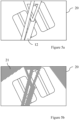
- Figures 5a to 5e show schematic views of the image 20 obtained by the method 100.
- the image 20 includes a view of components of the aircraft landing gear 10.
- the method 100 comprises determining a relative position of a component of the aircraft landing gear 10 which is used to determine the steering angle.
- the component comprises one of the tyres 11 of the aircraft landing gear 10 and in particular the tread 14 of the tyre 11.
- the image 20 shown in Figure 5a is obtained from the camera 15 positioned on the strut 12 of the aircraft landing gear 10 as shown in Figure 2 .
- the camera 15 is configured to capture a video of the aircraft landing gear 10 and a single frame of the video is obtained during the method 100 to determine the steering angle. This allows from the continual monitoring of the steering angle of the aircraft landing gear 10.
- the image 20 in Figure 5a is obtained from the camera 15, in some examples the image 20 is obtained from a memory on the aircraft 1, e.g. where the image 20 has been temporarily stored after previously being captured by the camera.
- the aircraft controller 5 After the image 20 has been obtained by the aircraft controller 5, the aircraft controller 5 performs the method 100 to perform 102 image pre-processing to the image 20. As shown in Figure 4 , the image pre-processing is applied before any subsequent image processing steps are performed.
- the image pre-processing includes applying a filter to the image 20 to greyscale the image 20. To grayscale the image 20, each pixel of the image 20 is converted to a shade of grey based on the brightness/luminance of the pixel. Converting the image to greyscale may help with subsequent image processing steps. For example, a grayscale image allows for the creation of a binary image (e.g. through image thresholding) which can then be used for subsequent image analysis.
- Performing 102 image pre-processing to the image 20 also includes performing gamma correction on the image 20.
- the gamma correction may help to correct the brightness level in the image 20 and may improve the subsequent image processing steps.
- O I 255 ⁇ ⁇ 255
- I is an input pixel value from the image 20
- ⁇ is the gamma correction value.
- the method 100 comprises determining 103 a region of disinterest in the image 20 and applying 104 a mask 21 to the image 20 to remove the region of disinterest from the image 20.
- Figure 5b shows a schematic view of the image 20 after the mask 21 has been applied.
- the mask 21, and therefore the region of disinterest is indicated by the hatched lines.
- the region of disinterest includes part of the image 20 in which the tyres 11 are not expected to be present in normal use. For example, in the image 20 of Figure 5a , the tyres 11 cannot be present in the location of the strut 12.
- this part of the image 20 is determined to be part of the area of disinterest and the mask 21 is applied to this area (as shown in Figure 5b ).
- this area is excluded from further analysis which may reduce computational requirements and increase the efficiency of the method 100.
- the region of disinterest in Figure 5b is determined by analysing a series of images of the aircraft landing gear 10 and determining which parts of the image do not vary significantly between sequential images.
- the series of images are a series of still images taken from the video of the aircraft landing gear 10 captured by the camera 15. It is assumed that any parts of the image which do not vary significantly between sequential images contain components which are substantially static/not moving. As such, these parts of the image are considered less relevant to the determination of the steering angle of the aircraft landing gear 10 and are attributed to the region of disinterest.
- a property of a pixel in one image varies by more than a threshold amount over the corresponding pixel in a subsequent or preceding image.
- the property comprises a pixel value which may include information such as the colour or intensity of the pixel. If the pixel does not vary by more than the threshold amount, that pixel is determined to be part of the region of disinterest.
- the threshold amount varies depending on conditions, such as lighting conditions, and can be empirically determined. For example, as the aircraft 1 travels over runway lights, this may affect the relative brightness of sequential images, meaning that a different threshold is required compared to a situation where the lighting conditions are constant.
- the threshold amount may also vary between different aircraft types.
- the region of disinterest is determined after the image 20 has been obtained in the method 100 of Figure 4 , in some examples the region of disinterest is determined or known before the image 20 is obtained and the mask 21, based on the region of disinterest, is applied after the image 20 is obtained.
- Information indicative of the mask 21 and/or region of disinterest is stored on the memory of the aircraft 1 to enable such information to be used in subsequent steering angle determinations. This may allow for quick and easy access to the information, which may increase the efficiency and/or speed of the method 100.
- the information is stored remotely from the aircraft 1, which may allow multiple aircraft 1 to access the information. This may also allow the information to be updated at a central location, rather than having to update the memory of each aircraft 1 individually. For example, the information may be updated if the configuration of the aircraft landing gear 10 is changed or if the position of the imaging device 15 is changed.
- the mask 21 and/or region of disinterest are constant for a given aircraft type.
- the method 100 comprises applying 105 a threshold to the image 20.
- Thresholding is a type of image segmentation which changes the pixels of the image 20 to make the image 20 easier to analyse.
- the greyscale image 20 is transformed into a binary image, i.e. a black and white image.
- the threshold applied to the image 20 replaces each pixel in the image with a black pixel if the intensity of the pixel is less than a threshold value and a white pixel if the intensity is greater than the threshold value.
- the threshold value is pre-determined and constant for the entire image 20.
- the threshold described above uses a pre-determined threshold value which is not dependent on the image 20 being analysed. In some examples, it is desirable to apply a tailored threshold to the image 20 which is better suited to the particular image 20.
- a threshold comprises Otsu thresholding (also known as Otsu's binarization or Otsu's method). Otsu thresholding determines an optimal global threshold from an image histogram. All possible threshold values are iterated and the spread of pixel levels is determined, i.e. the number of pixels that are in the background vs the number of pixels that are in the foreground, with the aim of determining the threshold value which makes these two numbers equal/close to equal.
- an adaptive threshold is used (also known as dynamic and/or local thresholding). Rather than using a single threshold value for the entire image 20, adaptive thresholding calculates a threshold based on a small region around a pixel, which can lead to different threshold values across the image 20. Examples of adaptive threshold which can be used include Mean or Gaussian thresholding. Mean thresholding takes the mean threshold of the pixels surrounding a given pixel, whereas in Gaussian thresholding the threshold value is the Gaussian weighted sum of neighbourhood values (i.e. of the pixels adjacent to the pixel being considered).
- the method also comprises determining 106 a region of interest of the image 20.
- the region of interest comprises part of the image 20 in which the tyres 11 are located.
- Determining 106 the region of interest comprises applying contour detection to the image 20.
- the contour detected image 20 is shown in Figure 5c . Contour detection enables the identification of borders of objects within an image.
- the contour detection is performed to locate the tyres 11, or a part thereof, within the image 20.
- the largest contour 22 that is detected is assumed to be a contour of the tyres 11.
- the region of interest 23 includes the contour 22 detected in Figure 5c .
- a smaller portion 24 of the region of interest 23 is selected. This helps to ensure that everything being considered is a part of the tyre 11 and is not a fringe section on the boundary of the tyre 11.
- the contents of subsection 24 are shown in more detail in Figure 5e .
- the method comprises performing 107 edge detection on the image 20.
- the edge detection is applied only to the portion 24 identified previously.
- Edge detection aims to identify edges within a digital image at which the image brightness changes sharply, i.e. where the image brightness is discontinuous.
- Edge detection processes can generally be grouped into two categories: search-based and zero-crossing based. In search-based methods, edges are detected by first computing a measure of the strength of the edges, e.g. using a first-order derivative expression such as the gradient magnitude, and then searching for local directional maxima of the gradient magnitude using a computed estimate of the local orientation of the edge, usually the gradient direction.
- edges are found by searching for zero crossings (the point where the sign of a mathematical function changes, i.e. the point at which the mathematical function crosses an axis) in a second-order derivative expression, such as the Laplacian, computed from the image.
- a second-order derivative expression such as the Laplacian
- Performing 107 edge detection on the image 20 comprises performing Canny edge detection.
- Canny edge detection is a particular type of edge detection which uses a multistage algorithm to detect a wide range of edges in images.
- a Gaussian filter is applied to the image to smooth the image and remove noise.
- An edge detection operator e.g. a Roberts, Prewitt or Sobel operator
- G x 2 + G y 2 ⁇ arctan G y G x
- the edge direction is rounded to one of four angles representing vertical, horizontal, and the two diagonals (i.e. 0°, 45°, 90° and 135°).
- a gradient magnitude threshold or lower bound cut-off suppression is applied to the image 20.
- This is an edge thinning technique which is used to remove unwanted spurious points on the edges of the image 20.
- Lower bound cut-off suppression is applied to find the locations with the sharpest change of intensity value.
- the edge strength of the current pixel is compared with the edge strength of the pixel in the positive and negative gradient directions. If the edge strength of the current pixel is the largest compared to the other pixels with the same direction (e.g. a pixel that is pointing in the y-direction will be compared to the pixel above and below it in the vertical axis), the value is preserved. Otherwise, the value will be suppressed.
- a double threshold is then applied to determine potential edges and to suppress weak edges.
- the previous edge thinning techniques means that the remaining edge pixels provide a more accurate representation of the edges of the image, some spurious edge pixels may remain.
- high and low threshold values are selected. If an edge pixel's gradient value is smaller than the high threshold value and larger than the low threshold value, it is marked as a weak edge pixel. If an edge pixel's gradient value is smaller than the low threshold value, it is suppressed.
- the thresholds selected are dependent on the image being analysed and are empirically determined.
- edges are finalised by suppressing any remaining weak edges which are not connected to strong edges.
- a weak edge which is associated with a true edge i.e. an actual edge of an object in the image
- any weak edge which is not attached to a strong edge is likely caused by noise/colour variations and can be suppressed. This is done by looking at a weak edge pixel and its eight connected neighbourhood pixels. As long as there is one strong edge pixel within the connected neighbourhood pixels, the weak edge pixel can be identified as one that should be preserved.
- the edge detection may comprise other algorithms.
- the edge detection may comprise Sobel, Prewitt or Roberts algorithms.
- the Hough transform is a feature extraction technique which is used to identify lines in an image.
- every point on a line can be described using a pair r, ⁇ (also known as Hough space), where r is the shortest distance from the origin to the closest point on the line (approaching the line perpendicularly) and ⁇ is the angle between the x-axis and a line connecting the origin with the closest point on the line.
- r x cos ⁇ + y sin ⁇
- Each point along a line in the portion 24 of the image 20 can be mapped as a sinusoid in Hough space, while each point in Hough space is mapped as a line in image space. Therefore, a point at which sinusoids intersect in Hough space indicates the presence of a straight line in the image 20.
- a relative angle of the tread 14 of the tyre 11 is determined.
- the relative angle of the tread 14 is the angle of the tread relative to the camera 15.
- the method 100 then comprises determining 109 the steering angle of the aircraft landing gear, based at least in part the relative angle of the tread 14 of the tyre 11.
- a median of the angles of the lines 25 is taken to determine the steering angle of the aircraft landing gear 10.
- another central tendency of the angles of the lines 25 may be determined, such as a mean or a mode of the angles of the lines 25.
- the predefined limit is a minimum length (e.g. minimum number of pixels) for a line to be considered an edge of the tread 14. Any lines below the predefined length are disregarded.
- the component may be another part of the aircraft landing gear 10.
- the component may be the torque link 13, where the torque link 13 comprises a reference mark 16 (as shown in Figure 3 ).
- the determining 108 the relative position of the component comprises determining, based at least in part on the edge obtained by the edge detection, the relative position of the reference mark 16.
- one reference mark 16 is shown in Figure 3
- the component the torque link 13 comprises a plurality of such reference marks.
- the reference mark 16 may help in determining the position of the torque link 13 relative the imaging device 15.
- the reference mark 16 may be less susceptible to external influence than the torque link 13 as a whole, e.g. it may be less likely that an external force moves the reference mark 16 in an undesirable/inconsistent way. Therefore, the reference mark 16 may provide a more consistent reference point for determining the position of the torque link 13.
- the reference mark 16 is arranged such that it is not occluded from the camera, even when a part of the torque link 13 is occluded from the camera. This may allow the position of the torque link 13 to be determined even when the part of the torque link is occluded.
- the reference mark 16 is omitted and the steering angle is determined based on an edge of the torque link 13 obtained by the edge detection.
- the component comprising the reference mark 16 is another component of the aircraft landing gear, for example a bogie of the aircraft landing gear 10.
- the method 100 comprises providing 110 information indicative of the steering angle of the aircraft landing gear 10 to the crew, e.g. the pilot, of the aircraft 1.
- the steering angle, or the information indicative of the steering angle is displayed in the cockpit 4 of the aircraft 1 such that it is easily available to the pilot. In this way, the pilot is informed of the steering angle of the aircraft landing gear even if the aircraft landing gear is not in their direct sight. This may help the pilot with manoeuvring the aircraft 1 on the ground.
- the determined steering angle of the aircraft landing gear 10 is used to limit further movement/rotation of the aircraft landing gear 10. For example, if the steering angle of the aircraft landing gear 10 is determined to be at a maximum safe steering angle, the pilot is prevented from increasing the steering angle further. The pilot may also receive a warning or other feedback when the maximum steering angle is reached. In some examples, when the pilot is using a physical input to control the steering angle, physical feedback through the input, e.g. shaking of the input, may be provided to the pilot to indicate when the maximum steering angle is reached.
- the information indicative of the steering angle of the aircraft landing gear 10 is provided to the crew of the aircraft 1 while the aircraft 1 is not on the ground. This information may be used to determine whether the aircraft landing gear 10 is in the correct position/orientation for landing and/or cruise. This may allow the crew to make an informed decision on whether it is safe to continue with landing and/or continued flight.
- the determined steering angle is stored, for example on the memory of the aircraft 1. Additionally or alternatively, the determined steering angle is stored on a database accessible by the aircraft 1, for example a database remote from the aircraft 1. In this way, the determined steering angle can be used to aid future steering angle determination or can be reviewed post flight to determine and analyse the accuracy of the method 100. As such, improvements can be made to the method 100 from a review of previously determined steering angles.
- any one or more of the steps of performing 102 image pre-processing, determining 103 the region of disinterest, applying 104 the mask, applying 105 the threshold, determining 106 the region of interest and/or providing 110 information may be omitted from the method 100.
- the method 100 utilises edge detection in determining the steering angle of the aircraft landing gear 10, in some examples another form of feature detection may be used. For example, corner detection (where corners in an image are detected) or ridge detection (where ridges in an image are detected) may be used.
- Figure 6 shows a flow chart of a further method 200 of determining a steering angle of an aircraft landing gear 10.
- the method 200 is a computer-implemented method 200 of determining the steering angle of the aircraft landing gear 10.
- the method 200 is carried out by the aircraft controller 5 and comprises obtaining 201 an input image of the aircraft landing gear 10 and comparing 206 the input image against a plurality of reference images, e.g. a set of reference images or database of reference images.
- the plurality of reference images comprises images of the aircraft landing gear 10 at known steering angles.
- the method 200 comprises determining 207 a most similar reference image, where the most similar reference image comprises the reference image of the plurality of reference images most closely matched to the input image, and determining 208, based at least in part on the most similar reference image, the steering angle of the aircraft landing gear 10.
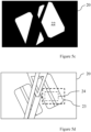
- Figure 7 shows a schematic illustration of the input image 220 and a reference image 230 of the plurality of reference images 230.
- the input image 220 and the reference image 230 are shown split into their respective red 221a, 231a, green 221b, 231b and blue 221c, 231c component planes.
- the method 200 comprises determining 202 a subset of the plurality of reference images 230 to be compared against the input image 220.
- the subset is determined based on a previous determination of the steering angle of the aircraft landing gear 10. As the steering angle will not be expected to have changed significantly from the previous determination, the subset can be focussed near to the previously determined steering angle to reduce the number of comparisons that are needed to be made. For example, when the steering angle has previously been determined to be at +20° (i.e. 20° clockwise, as viewed from above, such that the aircraft 1 would turn to the right when moving forward), the subset comprises reference images 230 which have steering angles within a predefined range of this steering angle.
- the subset when the predefined range is 10°, the subset will include the reference images 230 with a steering angle of between +10° and +30°.
- the predefined range may be 5°, 15°, 20°, 25°, 30° or any other suitable range.
- the subset is determined after the input image 220 has been obtained in Figure 6 , in some examples, the subset is determined before the input image 220 is obtained.
- the input image 220 obtained by the method 200 may not be in optimal condition to be compared against the plurality of reference images 230, the input image 220 is modified to help to address this.
- the input image 220 may contain excess noise which should be removed/reduced to improve the subsequent comparison. Therefore, after the input image is obtained, the method 200 comprises applying 203 a filter to the input image 220 to greyscale the image and processing 203 the input image to remove background noise from the input image.
- a filter to the input image 220 to greyscale the image and processing 203 the input image to remove background noise from the input image.
- each pixel of the input image 220 is converted to a shade of grey based on the brightness/luminance of the pixel.
- a smoothing filter such as a Gaussian smoothing, is applied to the input image 220.
- the brightness (or perceived brightness) of the input image 220 may be inconsistent with the brightness of each of the plurality of reference images 230.
- the method 200 comprises performing 205 gamma correction on the input image 220.
- the gamma correction is based on the gamma level of the plurality of reference images 230 and may help to improve the consistency of gamma levels between the input image 220 and the plurality of reference images 230. This may help to increase the accuracy of the comparison of the input image 220 against the plurality of reference images 230.
- the gamma correction may take the form as discussed in relation to the method of Figure 4 above.
- both the input image 220 and the plurality of reference images 230 are processed in the same way.
- the processing may comprise at least one of masking, histogram matching, cropping, blurring, contrast limited adaptive histogram matching, sharpening and denoising.
- reference images in the plurality of reference images 230 are compared against each other to determine how much corresponding pixels (and their pixel values) change between different reference images 230. Where a pixel value changes by less than a predetermined threshold value, those pixels are determined to be part of the background of the reference image 230 and are therefore not relevant to the determination of steering angle of the aircraft landing gear 10. The pixels which are determined to be part of the background are then masked from the input image 220 and the plurality of reference images 230.
- Histogram matching comprises modifying the input image 220 such that a histogram of the input image 220 matches a histogram of the plurality of reference images 230.
- the input image 220 and the plurality of reference images 230 are modified such that the histograms of the input image 220 and the plurality of reference images 230 match a predetermined histogram.
- contrast limited adaptive histogram matching may be used to match the histogram of the input image 220 and the histogram of the plurality of reference images 230.
- the input image 220 and the plurality of reference images 230 may be of interest when determining the steering angle
- the input image 220 and the plurality of reference images 230 may be cropped to only include a predetermined steering region.
- the steering region is a region within the input image 220 and the plurality of reference images 230 which includes the parts of the aircraft landing gear 10 that move when the steering angle changes.
- the input image 220 and the plurality of reference images 230 are smoothed by blurring.
- Blurring of the input image 220 and the plurality of reference images 230 is achieved by convolving the images with a low-pass filter kernel.
- the blurring may comprise averaging, Gaussian blurring, median blurring and/or bilateral filtering.
- a sharpening kernel such as that shown below, is applied to the input image 220 and each reference image 230 of the plurality of reference images 230. 0 ⁇ 1 0 ⁇ 1 5 ⁇ 1 0 ⁇ 1 0
- denoising the input image 220 and/or the plurality of reference images 230 comprises applying a non-local means denoising algorithm to the input image 220 and/or the plurality of reference images 230.
- Non-local means denoising comprises replacing the colour of an individual pixel in an image with an average of colours of similar pixels within the image.
- the method 200 comprises comparing 206 the input image 220 against the subset of the plurality of reference images 230 and determining 207 a most similar reference image 230.
- the most similar reference image 203 is the reference image 230 of the plurality of reference images 230 most closely matched to the input image 220.
- Comparing 206 the input image 220 against the plurality of reference images 230 comprises comparing input image pixel values of the input image 220 against corresponding reference image pixel values of each of the plurality of reference images 230. If a suitable match (i.e. a reference image 230 having a similarity characteristic within a predetermined threshold of the input image 220) is not found in the subset, the subset is expanded to include additional reference images 230 until a suitable match is found.
- the input image pixel values and the reference image pixel values comprise information indicative of the colours of pixels in the input image 220 and reference images 230 respectively.
- the input image 220 and the reference image 230 each comprise a red component value 221a, 231a, a green component value 221b, 231b and a blue component value 221c, 231c.
- the method 200 comprises calculating a similarity metric between the input image 220 and the reference image 230.
- the method comprises calculating the root mean square deviation (RMSD) between the input image pixel values and the corresponding reference image pixel values. This calculation is carried out for each of the reference images 230 in the subset, and the reference image 230 with the smallest RMSD between the input image pixel values and the reference image pixel values is determined to be the most similar reference image 230.
- a different similarity metric is calculated.
- the similarity metric may comprise the total number of pixel values in common between the input image 220 and the reference image 230.
- a respective similarity metric for each reference image may be determined and the reference image 230 with the similarity metric closest to a threshold value may be determined, wherein the threshold value is indicative of the highest degree of similarity.
- Another similarity metric which may be used is a cosine similarity.
- the input image pixel values are transformed into a one-dimensional input image vector and the reference image pixel values are transformed into a one-dimensional reference image vector.
- the cosine similarity between the input image vector and the reference image vector is then calculated. This calculation is carried out for each of the reference images 230 in the subset, and the reference image 230 with the greatest cosine similarity between the input image vector and the reference image vector is determined to be the most similar reference image 230.
- the input image pixels values and the reference image pixel values may comprise the intensity of the relevant pixels.
- the most similar reference image 230 is then the reference image 230 with the most pixels having the same or similar intensity as in the input image 220.
- determining 207 the most similar reference image 230 may comprise utilising a machine learning algorithm.
- the machine learning algorithm may comprise the input image 220 as an input, and the most similar reference image 230 as an output.
- Such a machine learning algorithm may be trained to provide its output based on a set of training data, for example a set of training data labelled with ground truth values in a supervised learning process.
- the plurality of reference images 230 at known steering angles may be used to train the machine learning algorithm.
- measured data may form a training data set.
- the machine learning algorithm may be updated in real-time based on data obtained by the aircraft 1, or other aircraft of the same type.
- the machine learning algorithm may comprise a neural network.
- the method 200 comprises determining 208 the steering angle of the aircraft landing gear 10. As the steering angle of each of the reference images 230 is known, the steering angle of the most similar reference image 230 is determined to be the steering angle of the aircraft landing gear 10.
- the method 200 comprises providing 209 information indicative of the steering angle of the aircraft landing gear 10 to the crew, e.g. the pilot, of the aircraft 1.
- the steering angle, or the information indicative of the steering angle is displayed in the cockpit 4 of the aircraft 1 such that it is easily available to the pilot. In this way, the pilot is informed of the steering angle of the aircraft landing gear even if the aircraft landing gear is not in their direct sight. This may help the pilot with manoeuvring the aircraft 1 on the ground.
- the determined steering angle of the aircraft landing gear 10 is used to limit further movement/rotation of the aircraft landing gear 10. For example, if the steering angle of the aircraft landing gear 10 is determined to be at a maximum safe steering angle, the pilot is prevented from increasing the steering angle further. The pilot may also receive a warning or other feedback when the maximum steering angle is reached. In some examples, when the pilot is using a physical input to control the steering angle, physical feedback through the input, e.g. shaking of the input, may be provided to the pilot to indicate when the maximum steering angle is reached.
- the information indicative of the steering angle of the aircraft landing gear 10 is provided to the crew of the aircraft 1 while the aircraft 1 is not on the ground. This information may be used to determine whether the aircraft landing gear is in the correct position/orientation for landing and/or cruise. This may allow the crew to make an informed decision on whether it is safe to continue with landing and/or continued flight.
- the determined steering angle is stored, for example on the memory of the aircraft 1. Additionally or alternatively, the determined steering angle is stored on a database accessible by the aircraft, for example a database remote from the aircraft 1. In this way, the determined steering angle can be used to aid future steering angle determination or can be reviewed post flight to determine and analyse the accuracy of the method 100. As such, improvements can be made to the method 100 from a review of previously determined steering angles.
- the method 200 as described above compares the input image 220 against the subset of the plurality of reference images 230
- the method 200 compares the input image 220 against all of the plurality of reference images 230.
- the plurality of reference images 230 comprises a series of images of the aircraft landing gear 10 where there is an interval of between 10° and 0.5° of steering angle between each image. In some examples, the interval may be between 8° and 0.5°, 6° and 0.5°, 4° and 0.5°, 2° and 0.5°, or 1° and 0.5°.
- the plurality of reference images covers a total range of steering angles of the aircraft landing gear 10 of 140°, i.e. between -70° (70° to the left) and +70° (70° to the right). In some examples, the total range is between 100° and 180°, between 120° and 160° or between 130° and 150°. In some examples, other ranges are also possible.
- the plurality of reference images 230 are generated by capturing images of the aircraft landing gear 10 while at the same time receiving information indicative of the steering angle of the aircraft landing gear 10.
- the images and their corresponding steering angles are saved to the memory, along with a mapping between the reference image 230 and the corresponding steering angle.
- the information indicative of the steering angle is determined by a sensor, e.g. a rotary variable differential transformer (RVDT), on the aircraft landing gear 10.
- RVDT rotary variable differential transformer
- the plurality of reference images 230 are stored on the memory of the aircraft 1. In this way, the plurality of reference images 230 can be quickly accessed by the method 200.
- the reference images are stored on a database accessible by the aircraft 1, such as a database remote from the aircraft 1. This may allow multiple aircraft 1 to access the plurality of reference images 230 and may also allow the plurality of reference images 230 to be updated at a central location, rather than having to update the memory of each aircraft 1 individually
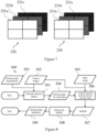
- a reference dataset (e.g. a plurality of reference images) is generated (box 301) by capturing images (box 302) of the aircraft landing gear with the camera while measuring 303 (box 303) the steering angle of the aircraft landing gear 10 and mapping the images to the corresponding measured steering angle, such that the steering angle of each frame captured by the camera is known (box 304).
- An input image 220 (box 305) from the camera is compared against the reference dataset to compute similarities (box 306). From this, the RMSD of each image in the reference dataset compared to the input image 220 is calculated (box 307).
- the reference image with the lowest associated RMSD is found (box 308) and is used to predict (box 309) the steering angle of the input image 220 and therefore the aircraft landing gear 10.
- any one or more of the steps of determining 202 the subset, applying 203 the filter, processing 204 the input image, performing 205 the gamma correction and/or providing 209 information may be omitted from the method 200.
- Figure 9 shows a flow chart of such a method 400 of determining a steering angle of the aircraft landing gear 10.
- the method 400 comprises determining 401 a condition affecting the aircraft landing gear 10.
- the condition is a determination of whether the tyre 11 of the aircraft landing gear is occluded from the camera.
- the condition may be another condition affecting the determination of the steering angle of the aircraft landing gear 10, such as a weather condition and/or an operation status of the imaging device 15.
- the method 400 comprises selecting 402 a first mode of determining the steering angle of the aircraft landing gear 10 or a second mode determining the steering angle of the aircraft landing gear 10, based at least in part on the condition.
- the first mode is the method 100 as described in relation to Figure 4 and the second mode is the method 200 as described in relation to Figure 6 .
- the optimal or preferred method for determining the steering angle of the aircraft landing gear 10 given the condition can be selected.
- the method 400 comprises determining 403 the steering angle of the aircraft landing gear 10 using the selected mode.
- the first and second modes are different method of determining the steering angle of the aircraft landing gear 10
- the first and second modes may have different failure conditions.
- the other mode/method can be selected.
- the optimal mode can be selected without having to rely on any other input/information. For example, it is not necessary for one of the modes to fail before the other mode is used.
- first mode is the method 100 as described in relation to Figure 4 and the second mode is the method 200 as described in relation to Figure 6
- the first mode and/or the second mode may comprise another method of determining the steering angle of the aircraft landing gear 10.
- the first mode and/or the second mode may comprise using a sensor, such as a rotary variable differential transformer (RVDT), to determine the steering angle of the aircraft landing gear 10, or may comprise using another suitable form of computer vision to determine the steering angle of the aircraft landing gear 10.
- RVDT rotary variable differential transformer
- Figure 10 shows a schematic diagram of a non-transitory computer-readable storage medium 500 according to an example.
- the non-transitory computer-readable storage medium 500 stores instructions 503 that, if executed by a processor 502 of an aircraft controller 501, cause the processor 502 to perform one of the methods described herein.
- the aircraft controller 501 is the aircraft controller 5 described above with reference to Figure 1 or a variant thereof described herein.
- the instructions 503 may comprise instructions to perform any of the methods 100, 200, 400 described above with reference to Figures 4 to 9 or variants thereof, such as those discussed herein.
Landscapes
- Engineering & Computer Science (AREA)
- Physics & Mathematics (AREA)
- General Physics & Mathematics (AREA)
- Theoretical Computer Science (AREA)
- Aviation & Aerospace Engineering (AREA)
- Computer Vision & Pattern Recognition (AREA)
- Geometry (AREA)
- Mechanical Engineering (AREA)
- Image Processing (AREA)
- Image Analysis (AREA)
- Length Measuring Devices By Optical Means (AREA)
Claims (14)
- Computerimplementiertes Verfahren zum Bestimmen eines Lenkwinkels eines Luftfahrzeugfahrwerks (10), wobei der Lenkwinkel zum Wenden eines Luftfahrzeugs (1) während einer Bewegung auf dem Boden eingestellt wird, das Verfahren umfassend:Erhalten eines Eingabebilds (20, 220) des Luftfahrzeugfahrwerks, wobei das Eingabebild durch eine Bildgebungsvorrichtung (15) aufgenommen wird, die auf einer Strebe des Luftfahrzeugfahrwerks positioniert ist, um sich direkt über einem Reifen des Luftfahrzeugfahrwerks zu befinden, wenn das Fahrwerk ausgefahren ist;Vergleichen des Eingabebilds mit einer Vielzahl von Referenzbildern (230), die Vielzahl von Referenzbildern umfassend Bilder des Luftfahrzeugfahrwerks bei bekannten Lenkwinkeln;Bestimmen eines ähnlichsten Referenzbilds, das ähnlichste Referenzbild umfassend ein Referenzbild der Vielzahl von Referenzbildern, das mit dem Eingabebild am meisten übereinstimmt; undBestimmen, basierend mindestens teilweise auf dem ähnlichsten Referenzbild, des Lenkwinkels des Luftfahrzeugfahrwerks.
- Verfahren nach Anspruch 1, wobei das Vergleichen des Eingabebilds mit der Vielzahl von Referenzbildern das Vergleichen von Eingabebildpixelwerten mit entsprechenden Referenzbildpixelwerten jedes der Vielzahl von Referenzbildern umfasst.
- Verfahren nach Anspruch 2, wobei das Vergleichen der Eingabebildpixelwerte mit den entsprechenden Referenzbildpixelwerten ein Berechnen der Standardabweichung (RMSD) zwischen den Eingabebildpixelwerten und den entsprechenden Referenzbildpixelwerten umfasst, optional wobei das Bestimmen des ähnlichsten Referenzbilds das Bestimmen des Referenzbilds mit der kleinsten Standardabweichung zwischen dem Eingabebildpixelwert und dem entsprechenden Referenzbildpixelwert umfasst.
- Verfahren nach einem der Ansprüche 1 bis 3, umfassend das Bestimmen einer Teilmenge der Vielzahl von Referenzbildern, die mit dem Eingabebild verglichen werden sollen, und das Vergleichen des Eingabebilds mit der Teilmenge.
- Verfahren nach Anspruch 4, wobei das Bestimmen der Teilmenge das Bestimmen der Teilmenge basierend auf einer vorherigen Bestimmung des Lenkwinkels des Luftfahrzeugfahrwerks umfasst.
- Verfahren nach einem der Ansprüche 1 bis 5, umfassend das Bestimmen eines Bereichs von Interesse des Bilds, der Bereich von Interesse umfassend einen Teil des Bilds, in dem sich eine Komponente von Interesse des Luftfahrzeugfahrwerks in einem Normalbetrieb voraussichtlich befindet, wobei das Vergleichen des Eingabebilds mit der Vielzahl von Referenzbildern das Vergleichen des Bereichs von Interesse mit der Vielzahl von Referenzbildern umfasst.
- Verfahren nach einem der Ansprüche 1 bis 6, umfassend mindestens eines von:Verarbeiten des Eingabebilds, um Hintergrundrauschen aus dem Eingabebild zu entfernen;Anwenden eines Filters auf das Eingabebild, um das Bild zu grauskalieren; undDurchführen einer Gammakorrektur an dem Eingabebild.
- Verfahren nach einem der Ansprüche 1 bis 7, wobei die Vielzahl von Referenzbildern durch Aufnehmen von Bildern des Luftfahrzeugfahrwerks, während Informationen empfangen werden, die den Lenkwinkel des Luftfahrzeugfahrwerks angeben, und Speichern der Bilder und des entsprechenden Lenkwinkels in einem Speicher erzeugt wird.
- Luftfahrzeugsteuereinrichtung (5) zum Bestimmen eines Lenkwinkels eines Luftfahrzeugfahrwerks (10), wobei der Lenkwinkel zum Wenden eines Luftfahrzeugs (1) während der Bewegung auf dem Boden eingestellt wird, wobei die Luftfahrzeugsteuereinrichtung konfiguriert ist zum:Erhalten eines Eingabebilds (20, 220) eines Luftfahrzeugfahrwerks, das durch eine Bildgebungsvorrichtung (15) aufgenommen wird, wobei die Bildgebungsvorrichtung auf einer Strebe des Luftfahrzeugfahrwerks positioniert ist, um sich direkt über einem Reifen des Luftfahrzeugfahrwerks zu befinden, wenn das Fahrwerk ausgefahren ist;Vergleichen des Eingabebilds mit einer Vielzahl von Referenzbildern (230), die Vielzahl von Referenzbildern umfassend Bilder des Luftfahrzeugfahrwerks bei bekannten Lenkwinkeln;Bestimmen eines ähnlichsten Referenzbilds, das ähnlichste Referenzbild umfassend das Referenzbild der Vielzahl von Referenzbildern, das mit dem Eingabebild am meisten übereinstimmt; undBestimmen, basierend mindestens teilweise auf dem ähnlichsten Referenzbild, des Lenkwinkels des Luftfahrzeugfahrwerks.
- System (17) zum Bestimmen eines Lenkwinkels eines Luftfahrzeugfahrwerks, wobei der Lenkwinkel zum Wenden eines Luftfahrzeugs (1) während der Bewegung auf dem Boden eingestellt wird, das System umfassend:eine Bildgebungsvorrichtung (15), die sich auf einem Teil des Luftfahrzeugs befindet, der im Blickfeld des Luftfahrzeugfahrwerks liegt; unddie Luftfahrzeugsteuereinrichtung (5) nach Anspruch 9.
- System nach Anspruch 10, wobei die Bildgebungsvorrichtung eine erste Bildgebungsvorrichtung und eine zweite Bildgebungsvorrichtung umfasst.
- System nach Anspruch 11, wobei die erste Bildgebungsvorrichtung und die zweite Bildgebungsvorrichtung unterschiedliche Arten von Bildgebungsvorrichtungen sind, optional wobei die erste Bildgebungsvorrichtung einen Lidar-Sensor umfasst und die zweite Bildgebungsvorrichtung eine Kamera umfasst.
- Nicht flüchtiges, computerlesbares Speicherungsmedium (500), das Anweisungen (503) speichert, die, wenn sie durch eine Luftfahrzeugsteuereinrichtung (501) ausgeführt werden, die Luftfahrzeugsteuereinrichtung veranlassen, das Verfahren nach einem der Ansprüche 1 bis 8 vorzunehmen.
- Luftfahrzeug (1), umfassend das System (17) nach einem der Ansprüche 10 bis 12.
Applications Claiming Priority (1)
| Application Number | Priority Date | Filing Date | Title |
|---|---|---|---|
| GB2202763.5A GB2616077A (en) | 2022-02-28 | 2022-02-28 | Aircraft steering angle determination |
Publications (2)
| Publication Number | Publication Date |
|---|---|
| EP4235576A1 EP4235576A1 (de) | 2023-08-30 |
| EP4235576B1 true EP4235576B1 (de) | 2025-04-02 |
Family
ID=81075473
Family Applications (1)
| Application Number | Title | Priority Date | Filing Date |
|---|---|---|---|
| EP23158967.2A Active EP4235576B1 (de) | 2022-02-28 | 2023-02-28 | Bestimmung des lenkwinkels eines flugzeuges |
Country Status (4)
| Country | Link |
|---|---|
| US (1) | US12524905B2 (de) |
| EP (1) | EP4235576B1 (de) |
| CN (1) | CN116664655A (de) |
| GB (1) | GB2616077A (de) |
Families Citing this family (3)
| Publication number | Priority date | Publication date | Assignee | Title |
|---|---|---|---|---|
| FR3148581A1 (fr) * | 2023-05-10 | 2024-11-15 | Safran Landing Systems | Contrôle d’un amortisseur du train d’atterrissage d’un aéronef |
| FR3158790B1 (fr) * | 2024-01-29 | 2026-02-06 | Airbus | Procédé de détermination d’au moins une caractéristique d’un mouvement d’une structure mobile d’un aéronef et aéronef comprenant un dispositif pour sa mise en œuvre |
| CN120229376B (zh) * | 2025-05-29 | 2025-07-29 | 中航(成都)无人机系统股份有限公司 | 飞机前轮电气零位标定方法、装置、设备及介质 |
Citations (4)
| Publication number | Priority date | Publication date | Assignee | Title |
|---|---|---|---|---|
| JP2012176656A (ja) * | 2011-02-25 | 2012-09-13 | Fuji Heavy Ind Ltd | 駐車支援装置 |
| US20150002620A1 (en) * | 2012-03-09 | 2015-01-01 | Lg Electronics Inc. | Image display device and method thereof |
| US20160216128A1 (en) * | 2013-09-27 | 2016-07-28 | Nissan Motor Co., Ltd. | Estimated Route Presentation Apparatus and Estimated Route Presentation Method |
| EP3543086A1 (de) * | 2018-03-22 | 2019-09-25 | Visteon Global Technologies, Inc. | Verfahren zur vorhersage einer änderung einer bewegungsrichtung eines fahrzeugs |
Family Cites Families (27)
| Publication number | Priority date | Publication date | Assignee | Title |
|---|---|---|---|---|
| US6405975B1 (en) | 1995-12-19 | 2002-06-18 | The Boeing Company | Airplane ground maneuvering camera system |
| DE19757763A1 (de) | 1997-12-23 | 1999-07-01 | Bosch Gmbh Robert | Vorrichtung zum Bestimmen der Rad- und/oder Achsgeometrie von Kraftfahrzeugen |
| US6961445B1 (en) | 2001-05-04 | 2005-11-01 | Rockwell Collins | Image processing warning system |
| US6722610B1 (en) | 2002-11-25 | 2004-04-20 | The Boeing Company | Method, system, and computer program product for controlling maneuverable wheels on a vehicle |
| US8712603B2 (en) | 2004-08-17 | 2014-04-29 | Borealis Technical Limited | Aircraft drive |
| US8335382B2 (en) | 2007-05-18 | 2012-12-18 | The Boeing Company | Method and system for applying silhouette tracking to determine attitude of partially occluded objects |
| US8042765B1 (en) | 2008-05-20 | 2011-10-25 | Nance C Kirk | Aircraft landing gear compression rate monitor |
| US9085261B2 (en) | 2011-01-26 | 2015-07-21 | Magna Electronics Inc. | Rear vision system with trailer angle detection |
| US9568919B2 (en) | 2012-10-24 | 2017-02-14 | Aurora Flight Sciences Corporation | System and methods for automatically landing aircraft |
| CN104006790A (zh) | 2013-02-21 | 2014-08-27 | 成都海存艾匹科技有限公司 | 基于视觉的飞机降落辅助装置 |
| US10365094B2 (en) | 2013-10-22 | 2019-07-30 | Pooja Arora | Optical device and method for wheel alignment |
| US9047771B1 (en) * | 2014-03-07 | 2015-06-02 | The Boeing Company | Systems and methods for ground collision avoidance |
| WO2016011099A1 (en) * | 2014-07-18 | 2016-01-21 | Sikorsky Aircraft Corporation | System for determining weight-on-wheels using lidar |
| US9786042B2 (en) | 2015-01-29 | 2017-10-10 | Honeywell International Inc. | Algorithm for measuring wear pin length using an input image |
| US11319086B2 (en) * | 2016-05-23 | 2022-05-03 | Rosemount Aerospace Inc. | Method and system for aligning a taxi-assist camera |
| US10618669B2 (en) | 2017-10-18 | 2020-04-14 | Goodrich Corporation | Method of determining aircraft ground speed |
| JP6896596B2 (ja) | 2017-12-14 | 2021-06-30 | 株式会社ブリヂストン | タイヤ溝残量管理システム |
| US10282834B1 (en) | 2018-06-22 | 2019-05-07 | Caterpillar Inc. | Measurement platform that automatically determines wear of machine components based on images |
| GB2576787B (en) * | 2018-09-03 | 2022-05-11 | Ge Aviat Systems Ltd | Measuring weight and balance and optimizing center of gravity |
| FR3088760B1 (fr) | 2018-11-20 | 2021-06-25 | Airbus Sas | Détermination d'un état de piste à partir de mesures embarquées de contamination de piste, système et aéronef associés |
| FR3093183B1 (fr) | 2019-02-22 | 2021-02-19 | Safran Electronics & Defense | Procédé de détection d’une dégradation d’un pneumatique d’une roue |
| FR3098796B1 (fr) | 2019-07-18 | 2021-10-29 | Airbus | Procédé et système de surveillance d’un état d’une piste d’atterrissage sur laquelle un aéronef est susceptible de rouler. |
| GB2587416A (en) * | 2019-09-30 | 2021-03-31 | Airbus Operations Ltd | Landing gear position sensing |
| CN110838247B (zh) * | 2019-10-12 | 2022-02-22 | 中国商用飞机有限责任公司 | 用于防止飞机地面碰撞的预警方法及系统 |
| FR3112013B1 (fr) * | 2020-06-25 | 2022-12-23 | Airbus | Procédé et dispositif d’aide à la conduite d’un aéronef se déplaçant au sol. |
| JP7444127B2 (ja) | 2021-04-08 | 2024-03-06 | 株式会社デンソー | 航空機監視システム |
| GB2612297A (en) | 2021-09-28 | 2023-05-03 | Airbus Operations Ltd | Determining the steering angle of a landing gear assembly of an aircraft |
-
2022
- 2022-02-28 GB GB2202763.5A patent/GB2616077A/en active Pending
-
2023
- 2023-02-28 CN CN202310212697.8A patent/CN116664655A/zh active Pending
- 2023-02-28 US US18/115,244 patent/US12524905B2/en active Active
- 2023-02-28 EP EP23158967.2A patent/EP4235576B1/de active Active
Patent Citations (4)
| Publication number | Priority date | Publication date | Assignee | Title |
|---|---|---|---|---|
| JP2012176656A (ja) * | 2011-02-25 | 2012-09-13 | Fuji Heavy Ind Ltd | 駐車支援装置 |
| US20150002620A1 (en) * | 2012-03-09 | 2015-01-01 | Lg Electronics Inc. | Image display device and method thereof |
| US20160216128A1 (en) * | 2013-09-27 | 2016-07-28 | Nissan Motor Co., Ltd. | Estimated Route Presentation Apparatus and Estimated Route Presentation Method |
| EP3543086A1 (de) * | 2018-03-22 | 2019-09-25 | Visteon Global Technologies, Inc. | Verfahren zur vorhersage einer änderung einer bewegungsrichtung eines fahrzeugs |
Also Published As
| Publication number | Publication date |
|---|---|
| GB202202763D0 (en) | 2022-04-13 |
| US20230274459A1 (en) | 2023-08-31 |
| EP4235576A1 (de) | 2023-08-30 |
| US12524905B2 (en) | 2026-01-13 |
| GB2616077A (en) | 2023-08-30 |
| CN116664655A (zh) | 2023-08-29 |
Similar Documents
| Publication | Publication Date | Title |
|---|---|---|
| EP4235576B1 (de) | Bestimmung des lenkwinkels eines flugzeuges | |
| CN107330376B (zh) | 一种车道线识别方法及系统 | |
| CN114331986B (zh) | 一种基于无人机视觉的坝体裂纹识别与测量方法 | |
| US7826666B2 (en) | Methods and apparatus for runway segmentation using sensor analysis | |
| CN111079556A (zh) | 一种多时相无人机视频图像变化区域检测及分类方法 | |
| CN107463890B (zh) | 一种基于单目前视相机的前车检测与跟踪方法 | |
| CN104899554A (zh) | 一种基于单目视觉的车辆测距方法 | |
| CN106910204B (zh) | 一种对海面船只自动跟踪识别的方法和系统 | |
| CN105373135A (zh) | 一种基于机器视觉的飞机入坞引导和机型识别的方法及系统 | |
| Sang et al. | A robust lane detection algorithm adaptable to challenging weather conditions | |
| CN108830131A (zh) | 基于深度学习的交通目标检测与测距方法 | |
| CN112634294A (zh) | 用于测量语义分割网络的边界性能的方法 | |
| CN115578470A (zh) | 一种单目视觉定位方法、装置、存储介质和电子设备 | |
| CN106803066A (zh) | 一种基于Hough变换的车辆偏航角确定方法 | |
| CN118521985B (zh) | 一种道路环境感知方法和装置、系统、存储介质 | |
| Cario et al. | Lane detection and tracking problems in lane departure warning systems | |
| EP4242968A1 (de) | Bestimmung des lenkwinkels eines fahrwerks | |
| Zhou et al. | Road detection based on edge feature with GAC model in aerial image | |
| CN116740180A (zh) | 基于特征点的双机近距视觉相对定位方法 | |
| Shettar et al. | Lane Detection for Autonomous Vehicles using Image Transformation Techniques | |
| CN113971789A (zh) | 用于检测的方法和计算系统 | |
| Ye et al. | Line detection based on hough transform and its application | |
| Stojanović et al. | Improving Lane Annotation in Autonomous Driving Data Sets with Classical Computer Vision Techniques | |
| US12511915B2 (en) | Image processing apparatus | |
| CN120339983A (zh) | 一种多特征融合自适应滤波车道线检测及前车测距方法 |
Legal Events
| Date | Code | Title | Description |
|---|---|---|---|
| PUAI | Public reference made under article 153(3) epc to a published international application that has entered the european phase |
Free format text: ORIGINAL CODE: 0009012 |
|
| STAA | Information on the status of an ep patent application or granted ep patent |
Free format text: STATUS: THE APPLICATION HAS BEEN PUBLISHED |
|
| AK | Designated contracting states |
Kind code of ref document: A1 Designated state(s): AL AT BE BG CH CY CZ DE DK EE ES FI FR GB GR HR HU IE IS IT LI LT LU LV MC ME MK MT NL NO PL PT RO RS SE SI SK SM TR |
|
| STAA | Information on the status of an ep patent application or granted ep patent |
Free format text: STATUS: REQUEST FOR EXAMINATION WAS MADE |
|
| 17P | Request for examination filed |
Effective date: 20240229 |
|
| RBV | Designated contracting states (corrected) |
Designated state(s): AL AT BE BG CH CY CZ DE DK EE ES FI FR GB GR HR HU IE IS IT LI LT LU LV MC ME MK MT NL NO PL PT RO RS SE SI SK SM TR |
|
| STAA | Information on the status of an ep patent application or granted ep patent |
Free format text: STATUS: EXAMINATION IS IN PROGRESS |
|
| 17Q | First examination report despatched |
Effective date: 20240522 |
|
| GRAP | Despatch of communication of intention to grant a patent |
Free format text: ORIGINAL CODE: EPIDOSNIGR1 |
|
| STAA | Information on the status of an ep patent application or granted ep patent |
Free format text: STATUS: GRANT OF PATENT IS INTENDED |
|
| INTG | Intention to grant announced |
Effective date: 20241028 |
|
| GRAS | Grant fee paid |
Free format text: ORIGINAL CODE: EPIDOSNIGR3 |
|
| GRAA | (expected) grant |
Free format text: ORIGINAL CODE: 0009210 |
|
| STAA | Information on the status of an ep patent application or granted ep patent |
Free format text: STATUS: THE PATENT HAS BEEN GRANTED |
|
| AK | Designated contracting states |
Kind code of ref document: B1 Designated state(s): AL AT BE BG CH CY CZ DE DK EE ES FI FR GB GR HR HU IE IS IT LI LT LU LV MC ME MK MT NL NO PL PT RO RS SE SI SK SM TR |
|
| REG | Reference to a national code |
Ref country code: GB Ref legal event code: FG4D |
|
| REG | Reference to a national code |
Ref country code: CH Ref legal event code: EP |
|
| REG | Reference to a national code |
Ref country code: IE Ref legal event code: FG4D |
|
| REG | Reference to a national code |
Ref country code: DE Ref legal event code: R096 Ref document number: 602023002655 Country of ref document: DE |
|
| REG | Reference to a national code |
Ref country code: NL Ref legal event code: MP Effective date: 20250402 |
|
| PG25 | Lapsed in a contracting state [announced via postgrant information from national office to epo] |
Ref country code: NL Free format text: LAPSE BECAUSE OF FAILURE TO SUBMIT A TRANSLATION OF THE DESCRIPTION OR TO PAY THE FEE WITHIN THE PRESCRIBED TIME-LIMIT Effective date: 20250402 |
|
| REG | Reference to a national code |
Ref country code: AT Ref legal event code: MK05 Ref document number: 1782041 Country of ref document: AT Kind code of ref document: T Effective date: 20250402 |
|
| PG25 | Lapsed in a contracting state [announced via postgrant information from national office to epo] |
Ref country code: FI Free format text: LAPSE BECAUSE OF FAILURE TO SUBMIT A TRANSLATION OF THE DESCRIPTION OR TO PAY THE FEE WITHIN THE PRESCRIBED TIME-LIMIT Effective date: 20250402 Ref country code: ES Free format text: LAPSE BECAUSE OF FAILURE TO SUBMIT A TRANSLATION OF THE DESCRIPTION OR TO PAY THE FEE WITHIN THE PRESCRIBED TIME-LIMIT Effective date: 20250402 Ref country code: PT Free format text: LAPSE BECAUSE OF FAILURE TO SUBMIT A TRANSLATION OF THE DESCRIPTION OR TO PAY THE FEE WITHIN THE PRESCRIBED TIME-LIMIT Effective date: 20250804 |
|
| REG | Reference to a national code |
Ref country code: LT Ref legal event code: MG9D |
|
| PG25 | Lapsed in a contracting state [announced via postgrant information from national office to epo] |
Ref country code: NO Free format text: LAPSE BECAUSE OF FAILURE TO SUBMIT A TRANSLATION OF THE DESCRIPTION OR TO PAY THE FEE WITHIN THE PRESCRIBED TIME-LIMIT Effective date: 20250702 Ref country code: GR Free format text: LAPSE BECAUSE OF FAILURE TO SUBMIT A TRANSLATION OF THE DESCRIPTION OR TO PAY THE FEE WITHIN THE PRESCRIBED TIME-LIMIT Effective date: 20250703 |
|
| PG25 | Lapsed in a contracting state [announced via postgrant information from national office to epo] |
Ref country code: PL Free format text: LAPSE BECAUSE OF FAILURE TO SUBMIT A TRANSLATION OF THE DESCRIPTION OR TO PAY THE FEE WITHIN THE PRESCRIBED TIME-LIMIT Effective date: 20250402 |
|
| PG25 | Lapsed in a contracting state [announced via postgrant information from national office to epo] |
Ref country code: BG Free format text: LAPSE BECAUSE OF FAILURE TO SUBMIT A TRANSLATION OF THE DESCRIPTION OR TO PAY THE FEE WITHIN THE PRESCRIBED TIME-LIMIT Effective date: 20250402 |
|
| PG25 | Lapsed in a contracting state [announced via postgrant information from national office to epo] |
Ref country code: HR Free format text: LAPSE BECAUSE OF FAILURE TO SUBMIT A TRANSLATION OF THE DESCRIPTION OR TO PAY THE FEE WITHIN THE PRESCRIBED TIME-LIMIT Effective date: 20250402 |
|
| PG25 | Lapsed in a contracting state [announced via postgrant information from national office to epo] |
Ref country code: AT Free format text: LAPSE BECAUSE OF FAILURE TO SUBMIT A TRANSLATION OF THE DESCRIPTION OR TO PAY THE FEE WITHIN THE PRESCRIBED TIME-LIMIT Effective date: 20250402 |
|
| PG25 | Lapsed in a contracting state [announced via postgrant information from national office to epo] |
Ref country code: RS Free format text: LAPSE BECAUSE OF FAILURE TO SUBMIT A TRANSLATION OF THE DESCRIPTION OR TO PAY THE FEE WITHIN THE PRESCRIBED TIME-LIMIT Effective date: 20250702 |
|
| PG25 | Lapsed in a contracting state [announced via postgrant information from national office to epo] |
Ref country code: IS Free format text: LAPSE BECAUSE OF FAILURE TO SUBMIT A TRANSLATION OF THE DESCRIPTION OR TO PAY THE FEE WITHIN THE PRESCRIBED TIME-LIMIT Effective date: 20250802 |
|
| PG25 | Lapsed in a contracting state [announced via postgrant information from national office to epo] |
Ref country code: LV Free format text: LAPSE BECAUSE OF FAILURE TO SUBMIT A TRANSLATION OF THE DESCRIPTION OR TO PAY THE FEE WITHIN THE PRESCRIBED TIME-LIMIT Effective date: 20250402 |
|
| REG | Reference to a national code |
Ref country code: DE Ref legal event code: R097 Ref document number: 602023002655 Country of ref document: DE |
|
| PG25 | Lapsed in a contracting state [announced via postgrant information from national office to epo] |
Ref country code: SM Free format text: LAPSE BECAUSE OF FAILURE TO SUBMIT A TRANSLATION OF THE DESCRIPTION OR TO PAY THE FEE WITHIN THE PRESCRIBED TIME-LIMIT Effective date: 20250402 Ref country code: DK Free format text: LAPSE BECAUSE OF FAILURE TO SUBMIT A TRANSLATION OF THE DESCRIPTION OR TO PAY THE FEE WITHIN THE PRESCRIBED TIME-LIMIT Effective date: 20250402 |
|
| PG25 | Lapsed in a contracting state [announced via postgrant information from national office to epo] |
Ref country code: CZ Free format text: LAPSE BECAUSE OF FAILURE TO SUBMIT A TRANSLATION OF THE DESCRIPTION OR TO PAY THE FEE WITHIN THE PRESCRIBED TIME-LIMIT Effective date: 20250402 |
|
| PG25 | Lapsed in a contracting state [announced via postgrant information from national office to epo] |
Ref country code: EE Free format text: LAPSE BECAUSE OF FAILURE TO SUBMIT A TRANSLATION OF THE DESCRIPTION OR TO PAY THE FEE WITHIN THE PRESCRIBED TIME-LIMIT Effective date: 20250402 |
|
| PG25 | Lapsed in a contracting state [announced via postgrant information from national office to epo] |
Ref country code: SK Free format text: LAPSE BECAUSE OF FAILURE TO SUBMIT A TRANSLATION OF THE DESCRIPTION OR TO PAY THE FEE WITHIN THE PRESCRIBED TIME-LIMIT Effective date: 20250402 |
|
| PG25 | Lapsed in a contracting state [announced via postgrant information from national office to epo] |
Ref country code: IT Free format text: LAPSE BECAUSE OF FAILURE TO SUBMIT A TRANSLATION OF THE DESCRIPTION OR TO PAY THE FEE WITHIN THE PRESCRIBED TIME-LIMIT Effective date: 20250402 |
|
| PLBE | No opposition filed within time limit |
Free format text: ORIGINAL CODE: 0009261 |
|
| STAA | Information on the status of an ep patent application or granted ep patent |
Free format text: STATUS: NO OPPOSITION FILED WITHIN TIME LIMIT |
|
| REG | Reference to a national code |
Ref country code: CH Ref legal event code: L10 Free format text: ST27 STATUS EVENT CODE: U-0-0-L10-L00 (AS PROVIDED BY THE NATIONAL OFFICE) Effective date: 20260211 |
|
| 26N | No opposition filed |
Effective date: 20260105 |
|
| PGFP | Annual fee paid to national office [announced via postgrant information from national office to epo] |
Ref country code: DE Payment date: 20260218 Year of fee payment: 4 |
|
| PGFP | Annual fee paid to national office [announced via postgrant information from national office to epo] |
Ref country code: FR Payment date: 20260219 Year of fee payment: 4 |