EP4235701A1 - Appareil de coupe destiné à un panier à combustible contenant un combustible nucléaire irradié dans un réacteur à eau lourde - Google Patents
Appareil de coupe destiné à un panier à combustible contenant un combustible nucléaire irradié dans un réacteur à eau lourde Download PDFInfo
- Publication number
- EP4235701A1 EP4235701A1 EP21883291.3A EP21883291A EP4235701A1 EP 4235701 A1 EP4235701 A1 EP 4235701A1 EP 21883291 A EP21883291 A EP 21883291A EP 4235701 A1 EP4235701 A1 EP 4235701A1
- Authority
- EP
- European Patent Office
- Prior art keywords
- cutting
- fuel
- turn table
- fuel basket
- base
- Prior art date
- Legal status (The legal status is an assumption and is not a legal conclusion. Google has not performed a legal analysis and makes no representation as to the accuracy of the status listed.)
- Pending
Links
Images


Classifications
-
- G—PHYSICS
- G21—NUCLEAR PHYSICS; NUCLEAR ENGINEERING
- G21F—PROTECTION AGAINST X-RADIATION, GAMMA RADIATION, CORPUSCULAR RADIATION OR PARTICLE BOMBARDMENT; TREATING RADIOACTIVELY CONTAMINATED MATERIAL; DECONTAMINATION ARRANGEMENTS THEREFOR
- G21F9/00—Treating radioactively contaminated material; Decontamination arrangements therefor
-
- B—PERFORMING OPERATIONS; TRANSPORTING
- B23—MACHINE TOOLS; METAL-WORKING NOT OTHERWISE PROVIDED FOR
- B23C—MILLING
- B23C3/00—Milling particular work; Special milling operations; Machines therefor
- B23C3/02—Milling surfaces of revolution
- B23C3/04—Milling surfaces of revolution while revolving the work
-
- B—PERFORMING OPERATIONS; TRANSPORTING
- B23—MACHINE TOOLS; METAL-WORKING NOT OTHERWISE PROVIDED FOR
- B23Q—DETAILS, COMPONENTS, OR ACCESSORIES FOR MACHINE TOOLS, e.g. ARRANGEMENTS FOR COPYING OR CONTROLLING; MACHINE TOOLS IN GENERAL CHARACTERISED BY THE CONSTRUCTION OF PARTICULAR DETAILS OR COMPONENTS; COMBINATIONS OR ASSOCIATIONS OF METAL-WORKING MACHINES, NOT DIRECTED TO A PARTICULAR RESULT
- B23Q1/00—Members which are comprised in the general build-up of a form of machine, particularly relatively large fixed members
- B23Q1/25—Movable or adjustable work or tool supports
- B23Q1/44—Movable or adjustable work or tool supports using particular mechanisms
- B23Q1/48—Movable or adjustable work or tool supports using particular mechanisms with sliding pairs and rotating pairs
- B23Q1/4852—Movable or adjustable work or tool supports using particular mechanisms with sliding pairs and rotating pairs a single sliding pair followed perpendicularly by a single rotating pair
-
- B—PERFORMING OPERATIONS; TRANSPORTING
- B23—MACHINE TOOLS; METAL-WORKING NOT OTHERWISE PROVIDED FOR
- B23Q—DETAILS, COMPONENTS, OR ACCESSORIES FOR MACHINE TOOLS, e.g. ARRANGEMENTS FOR COPYING OR CONTROLLING; MACHINE TOOLS IN GENERAL CHARACTERISED BY THE CONSTRUCTION OF PARTICULAR DETAILS OR COMPONENTS; COMBINATIONS OR ASSOCIATIONS OF METAL-WORKING MACHINES, NOT DIRECTED TO A PARTICULAR RESULT
- B23Q39/00—Metal-working machines incorporating a plurality of sub-assemblies, each capable of performing a metal-working operation
- B23Q39/02—Metal-working machines incorporating a plurality of sub-assemblies, each capable of performing a metal-working operation the sub-assemblies being capable of being brought to act at a single operating station
- B23Q39/021—Metal-working machines incorporating a plurality of sub-assemblies, each capable of performing a metal-working operation the sub-assemblies being capable of being brought to act at a single operating station with a plurality of toolheads per workholder, whereby the toolhead is a main spindle, a multispindle, a revolver or the like
- B23Q39/025—Metal-working machines incorporating a plurality of sub-assemblies, each capable of performing a metal-working operation the sub-assemblies being capable of being brought to act at a single operating station with a plurality of toolheads per workholder, whereby the toolhead is a main spindle, a multispindle, a revolver or the like with different working directions of toolheads on same workholder
- B23Q39/026—Metal-working machines incorporating a plurality of sub-assemblies, each capable of performing a metal-working operation the sub-assemblies being capable of being brought to act at a single operating station with a plurality of toolheads per workholder, whereby the toolhead is a main spindle, a multispindle, a revolver or the like with different working directions of toolheads on same workholder simultaneous working of toolheads
-
- G—PHYSICS
- G21—NUCLEAR PHYSICS; NUCLEAR ENGINEERING
- G21C—NUCLEAR REACTORS
- G21C19/00—Arrangements for treating, for handling, or for facilitating the handling of, fuel or other materials which are used within the reactor, e.g. within its pressure vessel
- G21C19/32—Apparatus for removing radioactive objects or materials from the reactor discharge area, e.g. to a storage place; Apparatus for handling radioactive objects or materials within a storage place or removing them therefrom
-
- G—PHYSICS
- G21—NUCLEAR PHYSICS; NUCLEAR ENGINEERING
- G21D—NUCLEAR POWER PLANT
- G21D1/00—Details of nuclear power plant
- G21D1/003—Nuclear facilities decommissioning arrangements
-
- G—PHYSICS
- G21—NUCLEAR PHYSICS; NUCLEAR ENGINEERING
- G21F—PROTECTION AGAINST X-RADIATION, GAMMA RADIATION, CORPUSCULAR RADIATION OR PARTICLE BOMBARDMENT; TREATING RADIOACTIVELY CONTAMINATED MATERIAL; DECONTAMINATION ARRANGEMENTS THEREFOR
- G21F5/00—Transportable or portable shielded containers
- G21F5/005—Containers for solid radioactive wastes, e.g. for ultimate disposal
- G21F5/008—Containers for fuel elements
-
- G—PHYSICS
- G21—NUCLEAR PHYSICS; NUCLEAR ENGINEERING
- G21F—PROTECTION AGAINST X-RADIATION, GAMMA RADIATION, CORPUSCULAR RADIATION OR PARTICLE BOMBARDMENT; TREATING RADIOACTIVELY CONTAMINATED MATERIAL; DECONTAMINATION ARRANGEMENTS THEREFOR
- G21F9/00—Treating radioactively contaminated material; Decontamination arrangements therefor
- G21F9/28—Treating solids
- G21F9/30—Processing
-
- B—PERFORMING OPERATIONS; TRANSPORTING
- B23—MACHINE TOOLS; METAL-WORKING NOT OTHERWISE PROVIDED FOR
- B23C—MILLING
- B23C1/00—Milling machines not designed for particular work or special operations
- B23C1/10—Milling machines not designed for particular work or special operations with both horizontal and vertical working-spindles
-
- B—PERFORMING OPERATIONS; TRANSPORTING
- B23—MACHINE TOOLS; METAL-WORKING NOT OTHERWISE PROVIDED FOR
- B23C—MILLING
- B23C1/00—Milling machines not designed for particular work or special operations
- B23C1/14—Milling machines not designed for particular work or special operations with rotary work-carrying table
-
- B—PERFORMING OPERATIONS; TRANSPORTING
- B23—MACHINE TOOLS; METAL-WORKING NOT OTHERWISE PROVIDED FOR
- B23C—MILLING
- B23C2270/00—Details of milling machines, milling processes or milling tools not otherwise provided for
- B23C2270/02—Use of a particular power source
- B23C2270/027—Pneumatics
-
- Y—GENERAL TAGGING OF NEW TECHNOLOGICAL DEVELOPMENTS; GENERAL TAGGING OF CROSS-SECTIONAL TECHNOLOGIES SPANNING OVER SEVERAL SECTIONS OF THE IPC; TECHNICAL SUBJECTS COVERED BY FORMER USPC CROSS-REFERENCE ART COLLECTIONS [XRACs] AND DIGESTS
- Y02—TECHNOLOGIES OR APPLICATIONS FOR MITIGATION OR ADAPTATION AGAINST CLIMATE CHANGE
- Y02E—REDUCTION OF GREENHOUSE GAS [GHG] EMISSIONS, RELATED TO ENERGY GENERATION, TRANSMISSION OR DISTRIBUTION
- Y02E30/00—Energy generation of nuclear origin
- Y02E30/30—Nuclear fission reactors
Definitions
- the present disclosure relates to a cutting apparatus for a fuel basket accommodating spent nuclear fuel of a heavy water reactor and, more particularly, to a cutting apparatus for a fuel basket accommodating spent nuclear fuel of a heavy water reactor that cuts only the welded bead of the fuel basket instead of cutting through the fuel basket, so that the cover and the body of the fuel basket can be separated without damaging the spent nuclear fuel, and easily recovering cutting chips generated during the cutting process.
- spent fuel refers to nuclear fuel material used as fuel for a nuclear reactor or nuclear fuel material that has undergone nuclear fission by other methods and is called high-level radioactive waste as contrasted with low- and intermediate-level radioactive waste from gloves, clothes, and the like of operators at nuclear power plants.
- spent fuel is no different from pre-spent fuel in appearance.
- spent fuel has high radioactivity due to fission products having been generated during the nuclear fission reaction in the nuclear reactor and continuously generates heat even after the fission reaction is over. Therefore, such spent fuel is not to be allowed to come into direct contact with people when handled or stored and needs to be handled outside the shielding structure that blocks the radiation.
- the spent nuclear fuel Prior to final disposal in an underground landfill, such spent nuclear fuel is stored in a storage place in a state of being accommodated into a specially designed storage container.
- the spent nuclear fuel is kept in the Spent Fuel Bay (SFB) located inside the building and subjected to a long period of cooling, and only the spent nuclear fuel, which has been cooled in the SFB for more than 6 years and thus generates very little decay heat, is transported to and stored in a Spent Fuel Dry Storage Facility (SFDSF) outside the building.
- the spent nuclear fuel is transferred to the storage basket FB provided by being made of stainless steel as shown in FIG.
- a cutting device for cutting the FB in the SFB is not well prepared conventionally, and even when a cutting device is provided, there is a problem in that not only does the cutting operation take a great deal of time and effort but also damage may occur to the FA accommodated in the FB as the through-cutting is performed.
- the conventional cutting method has a problem in that it is difficult to recover the cutting chips generated during the cutting operation.
- Patent Document Korean Patent No. 10-1845493
- an objective of the present disclosure is to provide a cutting apparatus for a fuel basket accommodating spent nuclear fuel of a heavy water reactor, which is capable of cutting a welding bead of the fuel basket rather than making the fuel basket subject to through-cutting when a lid and a main body of the fuel basket are separated in order to withdraw spent nuclear fuel, thereby preventing the spent nuclear fuel from being damaged during a cutting process and preventing cutting chips generated during the cutting operation of the fuel basket from being scattered so that the cutting chips are easily recovered.
- a cutting apparatus for a fuel basket accommodating spent nuclear fuel of a heavy water reactor including: a vertical support arranged on one side of the base; a turn table arranged to be reciprocated between one side and an opposite side of the base and be horizontally rotatable on the base; a horizontal support arranged to extend from an upper-end of the vertical support in a horizontal direction toward the turn table; a side-cutting means arranged on the vertical support protruding toward the turn table for cutting a side welding bead of the fuel basket mounted on the turn table; and an upper-cutting means arranged on the horizontal support protruding toward the turn table for cutting an upper welding bead of the fuel basket mounted on the turn table.
- the base may be provided with a scattering-free film in a form of a partition arranged upward along edges thereof.
- the base may include, thereon: guide rails each arranged between one side and the opposite side of the base; a transfer table arranged to be movable along the guide rails and allowing the turn table to be arranged thereon; a worm wheel in a form of a ring arranged to be rotatable on the transfer table and provided with a toothed gear on a circumferential surface thereof; and a worm shaft engaged and coupled with the toothed gear of the worm wheel, wherein the turn table may be coupled with the worm wheel.
- the side-cutting means may include: a bracket fixed to the vertical support; an elevating screw arranged to be rotatable in the bracket; an inclined block screw-coupled with the elevating screw and provided with a downwardly inclined surface to be elevated in a height direction of the bracket by rotation of the elevating screw; a mount having an inclined surface corresponding to the inclined surface of the inclined block and arranged for moving straight toward the fuel basket of the turn table with respect to the bracket while cooperating with elevating action of the inclined block; and an air motor arranged in the mount and a cutting tip generating rotating force by power of the air motor.
- a plurality of clamps may be provided at edges of the turn table to clamp the fuel basket, and a positioning hub to be inserted into a central post of the fuel basket may be provided in a center of the turn table.
- a cutting apparatus for a fuel basket accommodating spent nuclear fuel of a heavy water reactor includes a side-cutting means and an upper-cutting means corresponding to welding parts of the side and upper surfaces of the fuel basket, which is an object to be cut and is rotated by a turn table, and cuts only a welding bead that is a welding part rather than making the fuel basket subject to through-cutting, through cutting means above, so that there is an effect of separating the lid and the main body of the fuel basket without damaging the spent nuclear fuel.
- the present disclosure can prevent cutting chips generated during a fuel basket cutting operation from going to bounce out of the base, thereby allowing the cutting chips to be collected on the base. Accordingly, the present disclosure has the effect that the cutting chips can be easily recovered.
- the present disclosure provides an air motor as a power source for the cutting means and installs a pneumatic sensor configured to measure the air pressure supplied to the air motor so that even when the air motor cuts not only the welding bead but also the lid and the body of the fuel basket, by allowing the cutting depth of a cutting tip by the air motor to be monitored through the measurement of the pneumatic sensor, there is an effect of preventing spent nuclear fuel from being damaged during the cutting operation of the fuel basket.
- cutting apparatus for a fuel basket accommodating spent nuclear fuel of a heavy water reactor according to an exemplary embodiment of the present disclosure
- the cutting apparatus exactly cuts the side welding part and the upper welding part of the fuel basket FB in the water of a spent fuel bay, so that the spent fuel may be withdrawn without damage. That is, the cutting apparatus is provided to cut only the welding bead, which is a welding part of a lid and a main body, rather than making the fuel basket subject to through-cutting, so that the spent nuclear fuel may be taken out of the fuel basket without damage.
- the cutting apparatus includes a base 100, a support 200, a turn table 300, a side-cutting means 400, and an upper-cutting means 500.
- the base 100 is configured to be supported on the ground and provides a workspace where cutting of the fuel basket FB is performed.
- the base 100 may be made in a form of a square panel and includes a lifting ring 110 for lifting and a support member 120 supported on the ground.
- the support 200 and cutting means 400 and 500, to be described later, are arranged on one side of the workspace of the base 100, and guide rails 130 are arranged to provide a path between one side and an opposite side of the base 100 in the workspace of the base 100.
- a transfer table 140 capable of reciprocating the guide rails 130 is arranged on the guide rails 130, and the transfer table 140 is arranged for moving straight by a transfer table driving unit 150.
- the transfer table driving unit 150 includes a motor (not shown) and a screw shaft 151.
- the screw shaft 151 and the transfer table 140 are screw- coupled together, and as the screw shaft 151 rotates in forward and reverse directions by the power of the motor, the transfer table 140 may move back and forth between the one side and the opposite side of the base 100.
- a shatterproof film 160 is arranged on the circumference of the base 100.
- the shatterproof film 160 is configured to prevent cutting chips generated in a process of separating the fuel basket FB through the cutting means 400 and 500 from going to bounce out of the base 100 and, after the cutting operation is completed, be able to easily recover the cutting chips.
- the scattering-free film 160 may be provided in a form of a partition in a vertical direction along the circumference of the base 100.
- the support 200 is configured to fix the cutting means 400 and 500 and is arranged on one side of the base 100.
- the support 200 includes a vertical support 210 and a horizontal support 220, wherein the side-cutting means 400 is arranged on the vertical support 210 and the upper-cutting means 500 is arranged on the horizontal support 220.
- the turn table 300 is configured to provide a space in which the fuel basket FB, which is a cutting object, may be seated and cut by the cutting means 400 and 500 to be described later.
- the rotation table 300 may be arranged on the transfer table 150 and arranged to be horizontally rotated with respect to the ground.
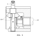
- the turn table 300 includes a positioning hub 310 and clamps 320 as shown in FIGS. 2 and 3 and is arranged so as to be rotated through a bevel gear 330 and a worm gear 340 as shown in FIGS. 4 and 5 .
- the positioning hub 310 serves to provide a guide for the position of the fuel basket FB on the turn table 300 and is provided in a form protruding upward from the turn table 300.
- the clamps 320 press sides of the fuel basket FB coupled with the positioning hub 310 to serve to restrain the fuel basket FB so as not to be moved on the turn table 300.
- a plurality of the clamps 320 is provided and is arranged so as to be reciprocally movable straight from the edge of the turn table 300 toward the positioning hub 310, and straight movement of the clamps 320 is performed through the clamp driving unit 350 shown in FIG. 6A .
- the clamp driving unit 350 includes a bevel gear 351, a transmission shaft 352 that transmits the power of the bevel gear 351, as shown in FIG. 6A , and a ring-shaped movable rotating plate 353 that may be screw-coupled with the clamps 320 as shown in FIG. 6B .
- a screw thread is provided in the circumferential direction of the moving turn plate 353. That is, by such a configuration, when the handle shaft H shown in FIGS2 and 6A is rotated in forward and reverse directions, the bevel gear 351 rotates the transmission shaft 352, and the transmission shaft 352 rotates to rotate the movable turn plate 353. According to this, the clamps 320 screw-coupled with the movable turn plate 353 may clamp the fuel basket FB while moving in a direction of the central axis of the movable turn plate 353.
- the turn table 300 is rotated on the transfer table 140 by the bevel gear 330 and the worm gear 340, and one side of the bevel gear 330 is connected to the handle shaft H protruding upward as shown in FIGS. 2 and 5 .
- the worm gear 340 includes a worm shaft 341 connected to an opposite side of the bevel gear 330 and a worm wheel 342 in gear coupling with the worm shaft 341.
- the worm wheel 342 is arranged between the transfer table 140 and the turn table 300 for interlocking with the turn table 300.
- the side-cutting means 400 is configured to cut the welding bead on the side of the fuel basket FB seated on the turn table 300 and, exactly, serves to cut the welding bead provided on the lower side of the fuel basket FB as shown in FIG. 3 .
- the parts where the welding bead of the fuel basket FB is provided are a lower side part and an upper center part, so the side-cutting means 400 is configured to cut the lower part of the side of the fuel basket FB, where one of the welding beads is.
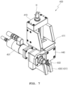
- the side cutting means 400 is arranged on the vertical support 210 as shown in FIG. 2 and includes a bracket 410, an elevating screw 420, an inclined block 430, a mount 440, and a cutting tip 450 as shown in FIGS. 7 to 8B .
- the bracket 410 of the side-cutting means 400 is configured to be fixed to the vertical support 210 and provides a path for the mount 440 to move straight.
- the bracket 410 provides a guide groove 411, to be described later, through which the mount 440 may move straight, and a stopper 412 is arranged at a lower end of the bracket 410.
- the stopper 412 is configured to limit excessive descent of the elevating screw 420.
- the elevating screw 420 is arranged to be rotatable in the bracket 410 and provides a screw thread. As shown in FIGS. 8A and 8B , the elevating screw 420 is screw-coupled with an inclination block 430 to be described later and is provided to elevate the inclination block 430 through rotations in forward and reverse directions.
- a handle shaft H is arranged at an upper-end part of the elevating screw 420.
- the inclined block 430 is screw-coupled with the elevating screw 420 and is provided for elevating with respect to the bracket 410 by rotation of the elevating screw 420.
- the inclined block 430 provides a downwardly inclined surface 431 that gradually widens from top to bottom.
- the mount 440 is configured to allow the cutting tip 450 to be arranged therein and provides an inclined surface 441 corresponding to the inclined surface 431 of the inclined block 430 as shown in FIGS. 8A and 8B .
- the mount 440 is coupled with a guide groove 411 of the bracket 410 and is arranged so as to be moved straight toward the fuel basket FB along the guide groove 411 by the elevating action of the inclined block 430.
- the cutting tip 450 is configured to directly cut the fuel basket FB and may be provided as an end mill. As shown in FIGS. 7 to 8B , the cutting tip 450 may be arranged to be rotatable by the power of the air motor 451.
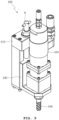
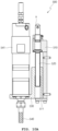
- the upper-cutting means 500 is configured to cut the welding bead provided in the upper center of the fuel basket FB and is arranged on the horizontal support 220 as shown in FIGS. 2 and 3 .
- the fuel basket FB is welded at the lower end of the side and the upper center, and the upper cutting means 500 is configured to cut an upper center welding bead as shown in FIG. 3 .
- the side-cutting means 400 is configured to move straight toward the side of the fuel basket FB
- the upper-cutting means 500 is configured to move straight toward the upper center of the fuel basket FB. As shown in FIGS.
- the upper-cutting means 500 includes a bracket 510, an elevating screw 520, an elevating member 530, and a cutting tip 540.
- the bracket 510 is configured to be fixed to the horizontal support 220 and provides an elevation path for an elevation member 530 to be described later.
- a stopper 511 is provided at the lower end part of the bracket 510 to limit excessive descent of the elevating member 530.
- the elevating screw 520 is arranged to be rotatable in the bracket 510 and provides a screw thread. At this time, the handle shaft H is connected to the upper-end part of the elevating screw 520.
- the elevating member 530 is screw-coupled with the elevating screw 520 and is arranged so as to elevate by rotation in forward and reverse directions of the elevating screw 520.
- the cutting tip 540 is configured to cut the upper center of the fuel basket FB and may be provided as an end mill.
- the cutting tip 540 is arranged on the elevating member 530 and is arranged to be rotatable by an air motor 541.
- the present disclosure has a technical feature of preventing the fuel basket FB from being subjected to through-cut by sensing the torque of the air motors 451 and 541, that is, the air pressure supplied to the air motors 451 and 541.
- a pneumatic sensor for measuring the air pressure supplied to the air motors 451 and 541 is further arranged in the air supply device outside the spent fuel bay, and the illustration of the air supply device and the pneumatic sensor is to be omitted for convenience.
- the operator hangs a lifting device on the lifting ring 110 and sinks the cutting apparatus into the spent fuel bay. Thereafter, the operator rotates the handle shafts H arranged on opposite sides of the turn table 300 using a manually operated rod (not shown) corresponding to the depth of the spent fuel bay.
- the bevel gear 351 and the transmission shaft 352 interlocked by the rotation of the handle shaft H rotate the moving turn plate 353, and while being moved to the edge of the turn table 300 by the rotation of the movable turn plate 353, the clamps 320 allow the turn table 300 to secure the space.
- the operator manipulates the fuel basket FB to sink in the spent fuel bay using the lifting device and then be seated on the turn table 300.
- the positioning hub 310 guides the position of the fuel basket FB while being inserted into the central post previously provided in the fuel basket FB.
- the operator reversely rotates the handles shaft H of the turn table 300 so that the clamps 320 come into close contact with and restrains the lower end of the fuel basket FB.
- the operator makes the cutting tip 450 of the side-cutting means 400 and the cutting tip 540 of the upper-cutting means 500 respectively correspond with the cutting parts of the fuel basket FB.
- the operator moves the cutting tip 450 back and forth toward the fuel basket FB. That is, as shown in FIGS. 8A and 8B , the side cutting means 400 is configured such that as the inclined block 430 is elevated by the rotation of the elevating screw 420, the mount 440 may move in back and forth directions along the inclined plane 431 of the inclined block 430.
- the elevating member 530 as shown in FIGS.
- the cutting tip 540 may be moved toward the upper center of the fuel basket FB in accordance therewith. Thereafter, when the positions of the cutting tips 450 and 540 correspond to the welding beads of the fuel basket FB, respectively, the operator actuates the air motors 451 and 541 through the air supply device to rotate the side-cutting means 400 and the upper-cutting means 500. Thereafter, the operator rotates the turn table 300 while rotating the handle shaft H connected to the bevel gear 330 of the worm shaft 341.
- the welding bead of the fuel basket FB is cut through the cutting tip.
- the operator may monitor the cutting depth of the cutting tip while monitoring the pneumatic sensor arranged in the air supply device. That is, when the air pressure supplied to the air motors 451 and 541 under a cutting operation is high compared to the air pressure reference value of the air pressure sensor preset through the test, the operator stops the operation of the air motors 451 and 541 and takes follow-up measures.
- the welding beads of the fuel basket FB are cut by thereof through the cutting means 400 and 500, respectively, and by performing the above-described process in reverse order to release the restraint of the fuel basket FB from the turn table 300, the cutting operation of the fuel basket by the cutting apparatus is completed.
Landscapes
- Engineering & Computer Science (AREA)
- Physics & Mathematics (AREA)
- Mechanical Engineering (AREA)
- General Engineering & Computer Science (AREA)
- High Energy & Nuclear Physics (AREA)
- Plasma & Fusion (AREA)
- Butt Welding And Welding Of Specific Article (AREA)
- Auxiliary Devices For Machine Tools (AREA)
Applications Claiming Priority (2)
| Application Number | Priority Date | Filing Date | Title |
|---|---|---|---|
| KR1020200137316A KR102351442B1 (ko) | 2020-10-22 | 2020-10-22 | 중수로 사용후핵연료가 수용된 연료바스켓의 절단장치 |
| PCT/KR2021/014818 WO2022086223A1 (fr) | 2020-10-22 | 2021-10-21 | Appareil de coupe destiné à un panier à combustible contenant un combustible nucléaire irradié dans un réacteur à eau lourde |
Publications (2)
| Publication Number | Publication Date |
|---|---|
| EP4235701A1 true EP4235701A1 (fr) | 2023-08-30 |
| EP4235701A4 EP4235701A4 (fr) | 2024-10-16 |
Family
ID=80051782
Family Applications (1)
| Application Number | Title | Priority Date | Filing Date |
|---|---|---|---|
| EP21883291.3A Pending EP4235701A4 (fr) | 2020-10-22 | 2021-10-21 | Appareil de coupe destiné à un panier à combustible contenant un combustible nucléaire irradié dans un réacteur à eau lourde |
Country Status (6)
| Country | Link |
|---|---|
| US (1) | US20240001459A1 (fr) |
| EP (1) | EP4235701A4 (fr) |
| KR (1) | KR102351442B1 (fr) |
| CN (1) | CN116508113A (fr) |
| CA (1) | CA3196331A1 (fr) |
| WO (1) | WO2022086223A1 (fr) |
Families Citing this family (9)
| Publication number | Priority date | Publication date | Assignee | Title |
|---|---|---|---|---|
| KR102830652B1 (ko) | 2023-01-04 | 2025-07-08 | 한국수력원자력 주식회사 | 원자로 엔드피팅 폐기물 처리 방법 및 장치 |
| KR102821141B1 (ko) | 2023-01-10 | 2025-06-17 | 한국수력원자력 주식회사 | 원자로 종단차폐체 해체 방법 및 장치 |
| KR102862174B1 (ko) | 2023-02-21 | 2025-09-19 | 한국수력원자력 주식회사 | 원자로 차폐볼 제거 방법 및 장치 |
| KR20250033821A (ko) * | 2023-09-01 | 2025-03-10 | 한국수력원자력 주식회사 | 레일형 대형 콘크리트 드럼 절단해체 시스템 및 방법 |
| KR102920784B1 (ko) | 2024-08-27 | 2026-02-02 | 한국원자력환경공단 | 사용후핵연료 캐니스터 인양장치 |
| KR102920783B1 (ko) | 2024-08-27 | 2026-02-02 | 한국원자력환경공단 | 건식환경의 사용후핵연료 캐니스터 뚜껑 절단 시스템 |
| KR102837748B1 (ko) | 2024-09-05 | 2025-07-24 | 한국원자력환경공단 | 사용후핵연료 캐니스터 뚜껑 절단장치 |
| TWI889575B (zh) * | 2024-10-16 | 2025-07-01 | 國家原子能科技研究院 | 一種鋼筒上蓋與外殼間銲道切割裝置 |
| KR102863225B1 (ko) | 2025-04-28 | 2025-09-22 | 한국원자력환경공단 | 사용후핵연료 운반 및 저장 겸용 캐니스터 뚜껑 절단을 위한 인양 장치 |
Family Cites Families (11)
| Publication number | Priority date | Publication date | Assignee | Title |
|---|---|---|---|---|
| US4003556A (en) * | 1974-10-02 | 1977-01-18 | Messer Griesheim Gmbh | Flame-cutting machine |
| JP2004020321A (ja) * | 2002-06-14 | 2004-01-22 | Mitsubishi Heavy Ind Ltd | キャニスタ切断装置 |
| JP2004347349A (ja) * | 2003-05-20 | 2004-12-09 | Toshiba Plant Systems & Services Corp | 水中解体装置 |
| KR100732031B1 (ko) * | 2006-04-11 | 2007-06-27 | 한국원자력연구원 | 사용후 핵연료봉 절단 장치 |
| JP5404439B2 (ja) * | 2010-01-14 | 2014-01-29 | 三菱重工業株式会社 | 補修装置 |
| KR101226689B1 (ko) * | 2011-07-08 | 2013-01-28 | 한전원자력연료 주식회사 | 중수로형 결함 연료봉 해체 절단기 및 그 방법 |
| KR101329083B1 (ko) * | 2012-02-24 | 2013-11-14 | 한국원자력연구원 | 사용후 핵연료 골격체용 절단장치 |
| KR101705995B1 (ko) * | 2015-11-24 | 2017-02-13 | 한전케이피에스 주식회사 | 방사선에 노출된 수중 고정볼트의 원격조작 절단장치 |
| KR101845493B1 (ko) | 2017-09-18 | 2018-04-05 | 주식회사 선광티앤에스 | 원자력 시설에서 발생되는 방사성 금속폐기물을 절단하기 위한 장치 |
| KR101857398B1 (ko) * | 2017-11-03 | 2018-05-11 | 한전케이피에스 주식회사 | 절단 장치 |
| KR101963587B1 (ko) * | 2018-03-13 | 2019-03-29 | (주)오르비텍 | 방사능 오염 폐드럼 절단장치 및 그 절단장치를 이용한 폐드럼 절단방법 |
-
2020
- 2020-10-22 KR KR1020200137316A patent/KR102351442B1/ko active Active
-
2021
- 2021-10-21 CA CA3196331A patent/CA3196331A1/fr active Pending
- 2021-10-21 CN CN202180071980.2A patent/CN116508113A/zh active Pending
- 2021-10-21 US US18/249,754 patent/US20240001459A1/en active Pending
- 2021-10-21 EP EP21883291.3A patent/EP4235701A4/fr active Pending
- 2021-10-21 WO PCT/KR2021/014818 patent/WO2022086223A1/fr not_active Ceased
Also Published As
| Publication number | Publication date |
|---|---|
| US20240001459A1 (en) | 2024-01-04 |
| CN116508113A (zh) | 2023-07-28 |
| CA3196331A1 (fr) | 2022-04-28 |
| WO2022086223A1 (fr) | 2022-04-28 |
| EP4235701A4 (fr) | 2024-10-16 |
| KR102351442B1 (ko) | 2022-01-17 |
Similar Documents
| Publication | Publication Date | Title |
|---|---|---|
| EP4235701A1 (fr) | Appareil de coupe destiné à un panier à combustible contenant un combustible nucléaire irradié dans un réacteur à eau lourde | |
| US5263062A (en) | Process and apparatus for dismantling the internal equipment of a water-cooled nuclear reactor | |
| US12100522B2 (en) | Apparatus and method for volume reduction for nuclear decommissioning and refurbishment | |
| JP2009047668A (ja) | 放射化された金属材料及び放射性ガスを含む密閉容器の切断・開封装置 | |
| DE8119452U1 (de) | Vorrichtung zum Zerkleinern von Werkstücken | |
| EP0096891A1 (fr) | Méthode et appareil pour changer les filtres d'une centrale nucléaire | |
| HU208589B (en) | Method and device for removing irradiated element of a nuclear reactor particularly tank of a pressurized water cooled nuclear reactor | |
| KR101777816B1 (ko) | 실시간 펀칭기 마모검사장치 | |
| US3672247A (en) | Apparatus and method for processing spent nuclear fuel elements | |
| US4975240A (en) | Docking arrangement for connecting a transport and storage container to a radioactively charged work chamber | |
| KR20190022243A (ko) | 방사선 폐기물 이송시스템용 드럼 회전장치 | |
| US4095495A (en) | Method and device for cutting a bundle of irradiated nuclear fuel tubes | |
| CN109748220A (zh) | 自动开封盖装置 | |
| CN114905552A (zh) | 重水堆乏燃料篮切割装置 | |
| US4217072A (en) | Method and apparatus for opening barrels and for emptying said barrels of their contents without polluting the environment | |
| KR100946316B1 (ko) | 고방사성 시료 이송장치 | |
| US3085327A (en) | Devices for opening and handling from a distance a container, and in particular an irradiated tube | |
| JPH0792518B2 (ja) | セル壁ポートからの物品の搬出入装置および搬出入方法 | |
| KR102027198B1 (ko) | 원자로 내부 구조물의 이송 장치 | |
| KR102920783B1 (ko) | 건식환경의 사용후핵연료 캐니스터 뚜껑 절단 시스템 | |
| RU2814651C1 (ru) | Станок для измельчения радиоактивных длинномерных элементов | |
| JPH07205946A (ja) | 破袋装置 | |
| US20060016856A1 (en) | Apparatus and method for sealing a container | |
| FR2672421A1 (fr) | Dispositif de decoupage d'un composant d'un reacteur nucleaire. | |
| KR102837748B1 (ko) | 사용후핵연료 캐니스터 뚜껑 절단장치 |
Legal Events
| Date | Code | Title | Description |
|---|---|---|---|
| STAA | Information on the status of an ep patent application or granted ep patent |
Free format text: STATUS: THE INTERNATIONAL PUBLICATION HAS BEEN MADE |
|
| PUAI | Public reference made under article 153(3) epc to a published international application that has entered the european phase |
Free format text: ORIGINAL CODE: 0009012 |
|
| STAA | Information on the status of an ep patent application or granted ep patent |
Free format text: STATUS: REQUEST FOR EXAMINATION WAS MADE |
|
| 17P | Request for examination filed |
Effective date: 20230508 |
|
| AK | Designated contracting states |
Kind code of ref document: A1 Designated state(s): AL AT BE BG CH CY CZ DE DK EE ES FI FR GB GR HR HU IE IS IT LI LT LU LV MC MK MT NL NO PL PT RO RS SE SI SK SM TR |
|
| DAV | Request for validation of the european patent (deleted) | ||
| DAX | Request for extension of the european patent (deleted) | ||
| A4 | Supplementary search report drawn up and despatched |
Effective date: 20240916 |
|
| RIC1 | Information provided on ipc code assigned before grant |
Ipc: G21C 19/32 20060101ALI20240910BHEP Ipc: B23Q 1/48 20060101ALI20240910BHEP Ipc: B23Q 39/02 20060101ALI20240910BHEP Ipc: B23C 1/14 20060101ALI20240910BHEP Ipc: B23C 1/10 20060101ALI20240910BHEP Ipc: B23C 3/04 20060101ALI20240910BHEP Ipc: B23D 35/00 20060101ALI20240910BHEP Ipc: G21F 9/00 20060101ALI20240910BHEP Ipc: G21F 9/30 20060101AFI20240910BHEP |