EP4235884A1 - Elektrolytmembran, elektrolysevorrichtung und redox-durchflussbatterie - Google Patents
Elektrolytmembran, elektrolysevorrichtung und redox-durchflussbatterie Download PDFInfo
- Publication number
- EP4235884A1 EP4235884A1 EP21882771.5A EP21882771A EP4235884A1 EP 4235884 A1 EP4235884 A1 EP 4235884A1 EP 21882771 A EP21882771 A EP 21882771A EP 4235884 A1 EP4235884 A1 EP 4235884A1
- Authority
- EP
- European Patent Office
- Prior art keywords
- electrolyte membrane
- yarns
- aspect ratio
- maximum length
- sub
- Prior art date
- Legal status (The legal status is an assumption and is not a legal conclusion. Google has not performed a legal analysis and makes no representation as to the accuracy of the status listed.)
- Granted
Links
Images


Classifications
-
- C—CHEMISTRY; METALLURGY
- C25—ELECTROLYTIC OR ELECTROPHORETIC PROCESSES; APPARATUS THEREFOR
- C25B—ELECTROLYTIC OR ELECTROPHORETIC PROCESSES FOR THE PRODUCTION OF COMPOUNDS OR NON-METALS; APPARATUS THEREFOR
- C25B1/00—Electrolytic production of inorganic compounds or non-metals
- C25B1/01—Products
- C25B1/02—Hydrogen or oxygen
- C25B1/04—Hydrogen or oxygen by electrolysis of water
-
- C—CHEMISTRY; METALLURGY
- C25—ELECTROLYTIC OR ELECTROPHORETIC PROCESSES; APPARATUS THEREFOR
- C25B—ELECTROLYTIC OR ELECTROPHORETIC PROCESSES FOR THE PRODUCTION OF COMPOUNDS OR NON-METALS; APPARATUS THEREFOR
- C25B13/00—Diaphragms; Spacing elements
- C25B13/02—Diaphragms; Spacing elements characterised by shape or form
-
- C—CHEMISTRY; METALLURGY
- C25—ELECTROLYTIC OR ELECTROPHORETIC PROCESSES; APPARATUS THEREFOR
- C25B—ELECTROLYTIC OR ELECTROPHORETIC PROCESSES FOR THE PRODUCTION OF COMPOUNDS OR NON-METALS; APPARATUS THEREFOR
- C25B13/00—Diaphragms; Spacing elements
- C25B13/04—Diaphragms; Spacing elements characterised by the material
- C25B13/08—Diaphragms; Spacing elements characterised by the material based on organic materials
-
- H—ELECTRICITY
- H01—ELECTRIC ELEMENTS
- H01M—PROCESSES OR MEANS, e.g. BATTERIES, FOR THE DIRECT CONVERSION OF CHEMICAL ENERGY INTO ELECTRICAL ENERGY
- H01M8/00—Fuel cells; Manufacture thereof
- H01M8/10—Fuel cells with solid electrolytes
- H01M8/1016—Fuel cells with solid electrolytes characterised by the electrolyte material
- H01M8/1018—Polymeric electrolyte materials
- H01M8/1039—Polymeric electrolyte materials halogenated, e.g. sulfonated polyvinylidene fluorides
-
- H—ELECTRICITY
- H01—ELECTRIC ELEMENTS
- H01M—PROCESSES OR MEANS, e.g. BATTERIES, FOR THE DIRECT CONVERSION OF CHEMICAL ENERGY INTO ELECTRICAL ENERGY
- H01M8/00—Fuel cells; Manufacture thereof
- H01M8/10—Fuel cells with solid electrolytes
- H01M8/1016—Fuel cells with solid electrolytes characterised by the electrolyte material
- H01M8/1018—Polymeric electrolyte materials
- H01M8/1058—Polymeric electrolyte materials characterised by a porous support having no ion-conducting properties
-
- H—ELECTRICITY
- H01—ELECTRIC ELEMENTS
- H01M—PROCESSES OR MEANS, e.g. BATTERIES, FOR THE DIRECT CONVERSION OF CHEMICAL ENERGY INTO ELECTRICAL ENERGY
- H01M8/00—Fuel cells; Manufacture thereof
- H01M8/10—Fuel cells with solid electrolytes
- H01M8/1016—Fuel cells with solid electrolytes characterised by the electrolyte material
- H01M8/1018—Polymeric electrolyte materials
- H01M8/1065—Polymeric electrolyte materials characterised by the form, e.g. perforated or wave-shaped
-
- H—ELECTRICITY
- H01—ELECTRIC ELEMENTS
- H01M—PROCESSES OR MEANS, e.g. BATTERIES, FOR THE DIRECT CONVERSION OF CHEMICAL ENERGY INTO ELECTRICAL ENERGY
- H01M8/00—Fuel cells; Manufacture thereof
- H01M8/18—Regenerative fuel cells, e.g. redox flow batteries or secondary fuel cells
- H01M8/184—Regeneration by electrochemical means
- H01M8/188—Regeneration by electrochemical means by recharging of redox couples containing fluids; Redox flow type batteries
-
- Y—GENERAL TAGGING OF NEW TECHNOLOGICAL DEVELOPMENTS; GENERAL TAGGING OF CROSS-SECTIONAL TECHNOLOGIES SPANNING OVER SEVERAL SECTIONS OF THE IPC; TECHNICAL SUBJECTS COVERED BY FORMER USPC CROSS-REFERENCE ART COLLECTIONS [XRACs] AND DIGESTS
- Y02—TECHNOLOGIES OR APPLICATIONS FOR MITIGATION OR ADAPTATION AGAINST CLIMATE CHANGE
- Y02E—REDUCTION OF GREENHOUSE GAS [GHG] EMISSIONS, RELATED TO ENERGY GENERATION, TRANSMISSION OR DISTRIBUTION
- Y02E60/00—Enabling technologies; Technologies with a potential or indirect contribution to GHG emissions mitigation
- Y02E60/30—Hydrogen technology
- Y02E60/36—Hydrogen production from non-carbon containing sources, e.g. by water electrolysis
-
- Y—GENERAL TAGGING OF NEW TECHNOLOGICAL DEVELOPMENTS; GENERAL TAGGING OF CROSS-SECTIONAL TECHNOLOGIES SPANNING OVER SEVERAL SECTIONS OF THE IPC; TECHNICAL SUBJECTS COVERED BY FORMER USPC CROSS-REFERENCE ART COLLECTIONS [XRACs] AND DIGESTS
- Y02—TECHNOLOGIES OR APPLICATIONS FOR MITIGATION OR ADAPTATION AGAINST CLIMATE CHANGE
- Y02E—REDUCTION OF GREENHOUSE GAS [GHG] EMISSIONS, RELATED TO ENERGY GENERATION, TRANSMISSION OR DISTRIBUTION
- Y02E60/00—Enabling technologies; Technologies with a potential or indirect contribution to GHG emissions mitigation
- Y02E60/30—Hydrogen technology
- Y02E60/50—Fuel cells
Definitions
- the present invention relates to an electrolyte membrane, an electrolysis apparatus and a redox flow battery.
- Patent Document 1 discloses an electrolyte membrane containing a fluorinated polymer having ion-exchange groups and a woven fabric, and shows that by specifying the aperture ratio of the woven fabric, the denier of the woven fabric, and the relationship between the thickness of the electrolyte membrane and the ion exchange capacity of the fluorinated polymer, it is possible to reduce the electrolytic voltage when applied to a water electrolysis apparatus.
- Patent Document 1 WO2020/162511
- a cleaning treatment such as brushing the surface of the woven fabric may be applied to remove a foreign matter attached to the woven fabric.
- pinholes may occur in the electrolyte membrane containing a woven fabric that has undergone the cleaning treatment as described above, when it is used in a cell having an anode and a cathode under voltage for a prolonged period of time.
- pinholes are defects having holes penetrating therethrough, and if pinholes occur, for example, in applications to electrolysis or batteries, there will be problems such that the transfer amount of material between the anode/cathode or the cathode/anode separated by the electrolyte membrane will increase, or breakages or short-circuits are likely to start from such points.
- the present invention has been made in view of the above problem, and is concerned with providing an electrolyte membrane wherein pinholes are less likely to occur even when used in a cell having an anode and a cathode under voltage for a prolonged period of time, as well as an electrolysis apparatus and a redox flow battery containing the electrolyte membrane.
- the present inventors have found that in an electrolyte membrane comprising a fluorinated polymer having ion-exchange groups and a woven fabric composed of yarns A and yarns B orthogonal thereto, if the aspect ratio YA CA2 /YA CA1 of yarns A at the intersection of yarns A and yarns B exceeds 1, and is larger than the aspect ratio YA A2 /YA A1 of yarns A at the midpoint between yarns B, and further, the aspect ratio YA CB2 /YA CB1 of yarns B at the intersection of yarns A and yarns B exceeds 1, and is larger than the aspect ratio YA B2 /YA B1 of yarns B at the midpoint of yarns A, it is possible to obtain the desired effects, and thus have arrived at the present invention.
- the present invention provides an electrolyte membrane wherein pinholes are less likely to occur when used in a cell having an anode and a cathode under voltage for a prolonged period of time, as well as an electrolysis apparatus and redox flow battery containing the electrolyte membrane.
- an "ion-exchange group” is a group capable of exchanging at least some of the ions contained in this group to other ions, and, for example, the following sulfonic acid type functional group and carboxylic acid type functional group may be mentioned.
- a "sulfonic acid-type functional group” means a sulfonic acid group (-SOsH) or a sulfonic acid base (-SO 3 M 2 , where M 2 is an alkali metal or a quaternary ammonium cation).
- a “carboxylic acid-type functional group” means a carboxylic acid group (-COOH) or a carboxylic acid base (-COOM 1 , where M 1 is an alkali metal or a quaternary ammonium cation).
- a "precursor membrane” is a membrane containing a polymer having groups which can be converted to ion-exchange groups.
- groups which can be converted to ion-exchange groups means groups which can be converted to ion-exchange groups by treatment such as hydrolysis treatment or acidification treatment.
- groups which can be converted to sulfonic acid type functional groups means groups which can be converted to sulfonic acid type functional groups by treatment such as hydrolysis treatment or acidification treatment.
- groups which can be converted to carboxylic acid type functional groups means groups which can be converted to carboxylic acid type functional groups by known treatment such as hydrolysis treatment or acidification treatment.
- a "unit" in a polymer means an atomic group derived from a single monomer molecule, which is formed by polymerization of the monomer.
- the unit may be an atomic group formed directly by the polymerization reaction, or it may be an atomic group in which a part of the atomic group is converted to another structure by treating the polymer obtained by the polymerization reaction.
- a numerical range expressed by using " to " means a range which includes the numerical values listed before and after " to “ as the lower and upper limits.
- the electrolyte membrane of the present invention is an electrolyte membrane comprising a fluorinated polymer having ion-exchange groups and a woven fabric. Further, said woven fabric is composed of yarns A extending in one direction and yarns B extending in a direction orthogonal to the yarns A. Further, said yarns A and said yarns B are each made of a material which does not elute in an alkaline aqueous solution. Further, the aspect ratio YA CA2 /YA CA1 calculated by the method as described below exceeds 1 and is larger than the aspect ratio YA A2 /YA A1 calculated by the method as described below. Further, the aspect ratio YA CB2 /YA CB1 calculated by the method as described below exceeds 1 and is larger than the aspect ratio YA B2 /YA B1 calculated by the method as described below.
- pinholes are less likely to occur at the time when used in a cell having an anode and a cathode under voltage for a prolonged period of time. The details of the reason for this have not been clarified, but are assumed to be due to the following reasons.
- a cleaning treatment such as brushing the surface of the woven fabric may be applied to remove a foreign matter attached to the woven fabric.
- the yarns constituting the woven fabric may become misaligned. This is assumed to cause the electrolyte to swell in areas where the yarn density has decreased, and when the swelling comes into contact with other components in the cell, pinholes (holes in the membrane) are generated.
- the aspect ratio YA CA2 /YA CA1 exceeds 1 in the woven fabric contained in the electrolyte of the present invention.
- the aspect ratio YA CA2 /YA CA1 represents the aspect ratio of the cross sections of yarns A at the intersection of yarns A and yarns B, and the larger the aspect ratio YA CA2 /YA CA1 , the more crushed yarns A are in the thickness direction at the intersection.
- the aspect ratio YA A2 /YA A1 represents the aspect ratio of the cross sections of yarns A at the midpoint between yarns B.
- the aspect ratio YA CA2 /YA CA1 is larger than the aspect ratio YA A2 /YA A1 . It is considered that yarns A are thereby made to be less likely to move by a cleaning treatment, whereby the occurrence of misalignment of yarns is prevented.
- Fig. 1 is a partial plan view showing schematically an example of the electrolyte membrane of the present invention.
- the electrolyte membrane 10 has an electrolyte 12 and a woven fabric 14 disposed in the electrolyte 12.
- the woven fabric 14 comprises yarn 14A1, yarn 14A2, yarn 14A3 and yarn14A4, and yarn 14B1, yarn 14B2, yarn 14B3 and yarn14B4.
- Yarn 14A1, yarn 14A2, yarn 14A3 and yarn 14A4 correspond to yarns A constituting the woven fabric 14, and yarn 14B1, yarn 14B2, yarn 14B3 and yarn 14B4 correspond to yarns B constituting the woven fabric 14.
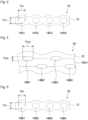
- Fig. 2 is a partial cross-sectional view showing an example when cut, in Fig. 1 , along the thickness direction of the electrolyte membrane through the center positions of yarns B in the electrolyte membrane, and specifically, is a cross-section exposed at the time when the electrolyte membrane 10 is cut along the CA-CA' line in Fig. 1 .
- the electrolyte 12 containing the fluorinated polymer (I) and yarn 14A1, yarn 14A2, yarn 14A3, yarn 14A4 and yarn 14B2, disposed in the electrolyte 12 are exposed.
- the maximum length Y CA1 in the thickness direction of the electrolyte membrane of yarns A and the maximum length Y CA2 in the direction orthogonal to the thickness direction of the electrolyte membrane of yarns A, in which the maximum length Y CA1 is measured, are measured.
- the electrolyte membrane 10 is cut along the CA-CA' line passing through the center position of the yarn 14B2 in the electrolyte membrane 10. This exposes a cross-section of the electrolyte membrane 10 as shown in Fig. 2 .
- the electrolyte membrane 10 is cut along the center position of yarn B other than 14B2 (e.g. yarn 14B3) to expose a cross-section of the electrolyte membrane 10.
- any optional yarn A (yarn 14A1 in Fig. 2 ) in each cross section is selected, and the maximum length Y CA2 and the maximum length Y CA1 in the selected yarn A are measured.
- Fig. 3 is a partial cross-sectional view showing an example when cut, in Fig. 1 , along the thickness direction of the electrolyte membrane in a direction parallel to the direction in which the yarns B in the electrolyte membrane extend and at the midpoint between the yarns B, and specifically, is the cross-section which is exposed when the electrolyte membrane 10 is cut along the A-A' line in Fig. 1 .
- the electrolyte 12 containing the fluorinated polymer (I) and yarn 14A1, yarn 14A2, yarn 14A3 and yarn 14A4, disposed in the electrolyte 12 are exposed.
- the maximum length Y A1 in the thickness direction of the electrolyte membrane of yarns A and the maximum length Y A2 in a direction perpendicular to the thickness direction of the electrolyte membrane of yarns A, in which the maximum length Y A1 is measured are measured.
- the electrolyte membrane 10 is cut at the A-A' line located in the midpoint between yarn 14B2 and yarn 14B3 in the electrolyte membrane 10. This exposes a cross-section of the electrolyte membrane 10 as shown in Fig. 3 .
- the electrolyte membrane 10 is cut at a position other than the midpoint between yarn 14B2 and yarn 14B3 (e.g. midpoint between yarn 14B3 and yarn 14B4) to expose a cross-section of the electrolyte membrane 10.
- any optional yarn A (yarn 14A1 in Fig. 2 ) in each cross section is selected, and the maximum length Y A2 and the maximum length Y A1 in the selected yarn A are measured.
- the lower limit of the aspect ratio YA CA2 /YA CA1 exceeds 1, and, from the viewpoint that the effect of the invention is more excellent, is preferably at least 1.2, more preferably at least 1.5, further preferably at least 2.0, particularly preferably at least 2.5, and most preferably at least 4.0.
- the upper limit of the aspect ratio YA CA2 /YA CA1 is preferably at most 7.0, more preferably at most 6.0, and particularly preferably at most 5.0, from such a viewpoint that the aperture ratio of the woven fabric may be made to be small, to prevent the voltage from increasing.
- the aspect ratio YA A2 /YA A1 is preferably from 0.5 to 3.5, more preferably from 0.8 to 3.5, and particularly preferably from 0.8 to 2.0, from such a viewpoint that the effects of the invention will be more excellent.
- the ratio of the aspect ratio YA CA2 /YA CA1 to the aspect ratio YA A2 /YA A1 exceeds 1 (that is, the aspect ratio YA CA2 /YA CA1 is larger than the aspect ratio YA A2 /YA A1 ), and from such a viewpoint that the effects of the present invention will be more excellent, is preferably at least 1.2, more preferably at least 1.4, further preferably at least 1.6, particularly preferably at least 2.2, and most preferably at least 2.4.
- the upper limit of the above ratio ((YA CA2 /YA CA1 )/(YA A2 /YA A1 )) is preferably at most 4.0, more preferably at most 3.5, and particularly preferably at most 3.0, from such a viewpoint that it is thereby possible to prevent the occurrence of current shielding due to too large flatness in the intersection area.
- the average maximum length YA CA2 is preferably from 20 to 160 ⁇ m, more preferably from 20 to 90 ⁇ m, and particularly preferably from 20 to 80 ⁇ m, from such a viewpoint that the effects of the present invention will be more excellent.
- the average maximum length YA CA1 is preferably from 10 to 80 ⁇ m, more preferably from 10 to 60 ⁇ m, and particularly preferably from 10 to 40 ⁇ m, from such a viewpoint that the effects of the present invention will be more excellent.
- the average maximum length YA A2 is preferably from 20 to 140 ⁇ m, more preferably from 20 to 80 ⁇ m, and particularly preferably from 20 to 60 ⁇ m, from such a viewpoint that the effects of the present invention will be more excellent.
- the average maximum length YA A1 is preferably from 20 to 80 ⁇ m, more preferably from 20 to 60 ⁇ m, and particularly preferably from 20 to 40 ⁇ m, from such a viewpoint that the effects of the present invention will be more excellent.
- Fig. 4 is a partial cross-sectional view showing an example when cut, in Fig. 1 , along the thickness direction of the electrolyte membrane through the center position of yarn A in the electrolyte membrane, and specifically, the cross-section which is exposed when the electrolyte membrane 10 is cut along the CB-CB' line in Fig. 1 .
- the electrolyte 12 containing the fluorinated polymer (I) and yarn 14B1, yarn 14B2, yarn 14B3, yarn 14B4 and yarn 14A1 disposed in the electrolyte 12 are exposed.
- the maximum length Y CB1 in the thickness direction of the electrolyte membrane of yarns B and the maximum length Y CB2 in the direction orthogonal to the thickness direction of the electrolyte membrane of yarns B, where the maximum length Y CB1 is measured are measured.
- the electrolyte membrane 10 is cut along the CB-CB' line passing through the center position of the yarn 14A1 in the electrolyte membrane. This exposes a cross-section of the electrolyte membrane 10 as shown in Fig. 4 .
- the electrolyte membrane 10 is cut along the center position of a yarn A other than 14A1 (e.g. yarn 14A2) to expose a cross-section of the electrolyte membrane 10.
- any optional yarn B (yarn 14B1 in Fig. 4 ) is selected, and the maximum length Y CB2 and the maximum length Y CB1 in the selected yarn B, are measured.
- Fig. 5 is a partial cross-sectional view showing an example when cut, in Fig. 1 , along the thickness direction of the electrolyte membrane in a direction parallel to the direction in which the yarns A in the electrolyte membrane extend and at the midpoint between the yarns A, and specifically, the cross section exposed when the electrolyte membrane 10 is cut along the B-B' line in Fig. 1 .
- the electrolyte 12 containing the fluorinated polymer (I) and yarn 14B1, yarn 14B2, yarn 14B3 and yarn 14B4 disposed in the electrolyte 12 are exposed.
- the maximum length Y B1 in the thickness direction of the electrolyte membrane of yarns B and the maximum length Y B2 in the direction orthogonal to the thickness direction of the electrolyte membrane of yarns B, in which the maximum length Y B1 is measured are measured.
- the electrolyte membrane 10 is cut at the B-B' line located at the midpoint between yarn 14A1 and yarn 14A2 in the electrolyte membrane 10. This exposes a cross-section of the electrolyte membrane 10 as shown in Fig. 5 .
- the electrolyte membrane 10 is cut at a position other than the midpoint between yarn 14A1 and yarn 14A2 (e.g. midpoint between yarn 14A2 and yarn 14A3) to expose a cross-section of the electrolyte membrane 10.
- any optional yarn B (yarn 14B1 in Fig. 5 ) in each cross section is selected, and the maximum length Y B2 and the maximum length Y B1 in the selected yarn B are measured.
- the lower limit of the aspect ratio YA CB2 /YA CB1 exceeds 1. From such a viewpoint that the effects of the present invention will be more excellent, at least 1.2 is preferred, at least 1.5 is more preferred, at least 2.0 is further preferred, at least 2.5 is particularly preferred, and at least 4.0 is most preferred.
- the upper limit of the aspect ratio YA CB2 /YA CB1 is preferably at most 7.0, more preferably at most 6.0, and particularly preferably at most 5.0, from such a viewpoint that it will be possible to prevent the voltage from increasing as the aperture ratio of the woven fabric will be small.
- the aspect ratio YA B2 /YA B1 is preferably from 0.5 to 3.5, more preferably from 0.8 to 3.5, and particularly preferably from 0.8 to 2.0, from such a viewpoint that the effects of the present invention will be more excellent.
- the ratio of the aspect ratio YA CB2 /YA CB1 to the aspect ratio YA B2 /YA B1 exceeds 1 (that is, the aspect ratio YA CB2 /YA CB1 is larger than the aspect ratio YA B2 /YA B1 ), and from such a viewpoint that the effects of the present invention will be more excellent, at least 1.2 is preferred, at least 1.4 is more preferred, at least 1.6 is further preferred, at least 2.2 is particularly preferred, and at least 2.4 is most preferred.
- the upper limit of the above ratio ((YA CB2 /YA CB1 )/(YA B2 /YA B1 )) is preferably at most 4.0, more preferably at most 3.5, and particularly preferably at most 3.0, from such a view point that it will be possible to prevent the occurrence of current shielding due to too large flatness in the intersection area.
- the average maximum length YA CB2 is preferably from 20 to 160 ⁇ m, more preferably from 20 to 90 ⁇ m, and particularly preferably from 20 to 80 ⁇ m, from such a viewpoint that the effects of the present invention will be more excellent.
- the average maximum length YA CB1 is preferably from 10 to 80 ⁇ m, more preferably from 10 to 60 ⁇ m, and particularly preferably from 10 to 40 ⁇ m, from such a viewpoint that the effects of the present invention will be more excellent.
- the average maximum length Y B2 is preferably from 20 to 140 ⁇ m, more preferably from 20 to 80 ⁇ m, and particularly preferably from 20 to 60 ⁇ m, from such a viewpoint that the effects of the present invention will be more excellent.
- the average maximum length Y B1 is preferably from 20 to 80 ⁇ m, more preferably from 20 to 60 ⁇ m, and particularly preferably from 20 to 40 ⁇ m, from such a viewpoint that the effects of the present invention will be more excellent.
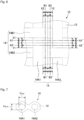
- Fig. 6 is a partial plan view having one part of the electrolyte membrane of Fig. 1 enlarged.
- the symbols for the respective components in Fig. 6 are the same as the symbols for the respective components in Fig. 1 .
- Fig. 7 is a partial cross-sectional view showing an example when cut, in Fig. 6 , along the thickness direction of the electrolyte membrane, in a direction parallel to the direction in which the yarns B in the electrolyte membrane extend, and at a point where the distance is 1/4 of the distance between the edge X1 and the edge Y1 of the two adjacent yarns B, from the edge X1 of one yarn B that is closer to the other yarn B toward the edge Y1 of the yarn that is closer to said one yarn B.
- Fig. 7 is the cross-section exposed when the electrolyte membrane 10 is cut at the A1-A1' line in Fig. 6 .
- the electrolyte 12 containing the fluorinated polymer (I) and yarn 14A1 and yarn 14A2 disposed in the electrolyte 12 are exposed.
- the maximum length Y A11 in the thickness direction of the electrolyte membrane of yarns A and the maximum length Y A12 in the direction orthogonal to the thickness direction of the electrolyte membrane of yarns A wherein the maximum length Y A11 is measured are measured.
- the electrolyte membrane 10 is cut at the A1-A1' line located at a point where the distance is 1/4 of the distance between the edge X1 and the edge Y1, from edge X1 toward edge Y1. This exposes a cross-section of the electrolyte membrane 10 as shown in Fig. 7 .
- the electrolyte membrane 10 is cut at a position other than between yarn 14B1 and yarn 14B2 to expose a cross-section of the electrolyte membrane 10.
- any optional yarn A (yarn 14A1 in Fig. 7 ) in each cross-section is selected, and the maximum length Y A12 and the maximum length Y A11 in the selected yarn A are measured.
- the aspect ratio YA A12 /YA A11 is preferably from 0.5 to 3.5, and particularly preferably from 0.8 to 2.0, from such a viewpoint that the effects of the present invention will be more excellent.
- the ratio of the aspect ratio YA CA2 /YA CA1 to the aspect ratio YA A12 /YA A11 preferably exceeds 1, more preferably at least 1.2, further preferably at least 1.4, still further preferably at least 1.6, particularly preferably at least 2.2, and most preferably at least 2.4, from such a viewpoint that the effects of the present invention will be more excellent.
- the upper limit of the above ratio ((YA CA2 /YA CA1 )/(YA A12 /YA A11 )) is preferably at most 4.0, more preferably at most 3.5, and particularly preferably at most 3.0, from such a viewpoint that it is possible to prevent the occurrence of current shielding due to too large flatness in the intersection area.
- the average maximum length YA A12 is preferably from 20 to 140 ⁇ m, more preferably from 20 to 80 ⁇ m, and particularly preferably from 20 to 60 ⁇ m, from such a viewpoint that the effects of the present invention will be more excellent.
- the average maximum length YA A11 is preferably from 20 to 80 ⁇ m, more preferably from 20 to 60 ⁇ m, and particularly preferably from 20 to 40 ⁇ m, from such a viewpoint that the effects of the present invention will be more excellent.
- Fig. 8 is a partial cross-sectional view showing an example when cut along the thickness direction of the electrolyte membrane in Fig. 6 , in a direction parallel to the direction in which the yarns B in the electrolyte membrane extend, and at a point where the distance is 3/4 of the distance between edge X1 and edge Y1 of the two adjacent yarns B, from the edge X1 of one yarn B closer to the other yarn B toward the edge Y1 of the other yarn B closer to the one yarn B.
- Fig. 8 is the cross-section exposed when the electrolyte membrane 10 is cut at the A2-A2' line in Fig. 6 .
- the electrolyte 12 containing the fluorinated polymer (I) and yarn 14A1 and yarn 14A2 disposed in the electrolyte 12 are exposed.
- the maximum length Y A21 in the thickness direction of the electrolyte membrane of yarns A and the maximum length Y A22 in the direction orthogonal to the thickness direction of the electrolyte membrane of yarns A wherein the maximum length Y A21 is measured are measured.
- the electrolyte membrane 10 is cut at the A2-A2' line located at the point where the distance is 3/4 of the distance between edge X1 and edge Y1 from edge X1 toward edge Y1. This exposes a cross-section of the electrolyte membrane 10 as shown in Fig. 8 .
- the electrolyte membrane 10 is cut at a position other than between yarn 14B1 and yarn 14B2, to expose a cross-section of the electrolyte membrane 10.
- any optional yarn A (yarn 14A1 in Fig. 8 ) in each section is selected, and the maximum length Y A22 and the maximum length Y A21 in the selected yarn A are measured.
- the ratio of the average maximum length YA A22 , which is the arithmetic mean of the obtained 10 maximum lengths Y A22 , to the average maximum length YA A21 , which is the arithmetic mean of the obtained 10 maximum lengths Y A21 , is adopted as the aspect ratio YA A22 /YA A21 .
- the aspect ratio YA A22 /YA A21 is preferably from 0.5 to 3.5, and particularly preferably from 0.8 to 2.0, from such a viewpoint that the effects of the present invention will be more excellent.
- the ratio of the aspect ratio YA CA2 /YA CA1 to the aspect ratio YA A22 /YA A21 preferably exceeds 1, and is more preferably at least 1.2, further preferably at least 1.4, still further preferably at least 1.6, particularly preferably at least 2.2, and most preferably at least 2.4, from such a viewpoint that the effects of the present invention will be more excellent.
- the upper limit of the above ratio ((YA CA2 /YA CA1 )/(YA A22 /YA A21 )) is at most 4.0, more preferably at most 3.5, and particularly preferably at most 3.0, from such a viewpoint that it will be possible to prevent the occurrence of current shielding due to too large flatness in the intersection area.
- the average maximum length YA A22 is preferably from 20 to 140 ⁇ m, more preferably from 20 to 80 ⁇ m, and particularly preferably from 20 to 60 ⁇ m, from such a viewpoint that the effects of the present invention will be more excellent.
- the average maximum length YA A21 is preferably from 20 to 80 ⁇ m, more preferably from 20 to 60 ⁇ m, and particularly preferably from 20 to 40 ⁇ m, from such a viewpoint that the effects of the present invention will be more excellent.
- Fig. 9 is a partial cross-sectional view showing an example when cut along the thickness direction of the electrolyte membrane in Fig. 6 , in a direction parallel to the direction in which yarns A in the electrolyte membrane extend, and at a point where the distance is 1/4 of the distance between edge X2 and edge Y2 of the adjacent two yarns A, from edge X2 of the one yarn A closer to the other yarn A toward edge Y2 of the other yarn A closer to said one yarn A.
- Fig. 9 is the cross-section exposed when the electrolyte membrane 10 is cut at the B1-B1' line in Fig. 6 .
- the electrolyte 12 containing the fluorinated polymer (I) and yarn 14B1 and yarn 14B2 disposed in the electrolyte 12 are exposed.
- the maximum length Y B11 in the thickness direction of the electrolyte membrane of yarns B and the maximum length Y B12 in the direction orthogonal to the thickness direction of the electrolyte membrane of yarns B in which the maximum length Y B11 is measured are measured.
- the electrolyte membrane 10 is cut at the B1-B1' line located at a point where the distance is 1/4 of the distance between edge X2 and edge Y2, from edge X2 to edge Y2. This exposes a cross-section of the electrolyte membrane 10 as shown in Fig. 9 .
- the electrolyte membrane 10 is cut at a position other than between yarn 14A1 and yarn 14A2 to expose a cross-section of the electrolyte membrane 10.
- any optional yarn B (yarn 14B1 in Fig. 9 ) in each section is selected, and the maximum length Y B12 and the maximum length Y B11 in the selected yarn B, are measured.
- the aspect ratio YA B12 /YA B11 is preferably from 0.5 to 3.5, and particularly preferably from 0.8 to 2.0, from such a viewpoint that the effects of the present invention will be more excellent.
- the ratio of the aspect ratio YA CB2 /YA CB1 to the aspect ratio YA B12 /YA B11 preferably exceeds 1, and is more preferably at least 1.2, further preferably at least 1.4, still further preferably at least 1.6, particularly preferably at least 2.2, and most preferably at least 2.4, from such a viewpoint that the effects of the present invention will be more excellent.
- the upper limit of the above ratio ((YA CB2 /YA CB1 )/(YA B12 /YA B11 )) is preferably at most 4.0, more preferably at most 3.5, and particularly preferably at most 3.0, from such a viewpoint that it will be possible to prevent the occurrence of current shielding due to too large flatness in the intersection area.
- the average maximum length YA B12 is preferably from 20 to 140 ⁇ m, more preferably from 20 to 80 ⁇ m, and particularly preferably from 20 to 60 ⁇ m, from such a viewpoint that the effects of the present invention will be more excellent.
- the average maximum length YA B11 is preferably from 20 to 80 ⁇ m, more preferably from 20 to 60 ⁇ m, and particularly preferably from 20 to 40 ⁇ m, from such a viewpoint that the effects of the present invention will be more excellent.
- Fig. 10 is a partial cross-sectional view showing an example when cut along the thickness direction of the electrolyte membrane in Fig. 6 , in a direction parallel to the direction in which yarns A in the electrolyte membrane extend, and at a point where the distance is 3/4 of the distance between edge X2 and edge Y2 of the two adjacent yarns A, from edge X2 of one yarn A closer to the other yarn A toward edge Y2 of the other yarn A closer to the one yarn A.
- Fig. 10 is the cross-section exposed when the electrolyte membrane 10 is cut at the B2-B2' line in Fig. 6 .
- the electrolyte 12 containing the fluorinated polymer (I) and yarn 14B1 and yarn 14B2 disposed in the electrolyte 12 are exposed.
- the maximum length Y B21 in the thickness direction of the electrolyte membrane of yarns B and the maximum length Y B22 in the direction orthogonal to the thickness direction of the electrolyte membrane of yarns B wherein the maximum length Y B21 is measured are measured.
- the electrolyte membrane 10 is cut at the B2-B2' line located at a point where the distance is 3/4 of the distance between edge X2 and edge Y2, from edge X2 to edge Y2. This exposes a cross-section of the electrolyte membrane 10 as shown in Fig. 10 .
- the electrolyte membrane 10 is cut at a position other than between yarn 14A1 and yarn 14A2 to expose a cross-section of the electrolyte membrane 10.
- any optional yarn B (yarn 14B1 in Fig. 10 ) in each cross section is selected, and the maximum length Y B22 and the maximum length Y B21 for each cross section in the selected yarn B are measured.
- the ratio of the average maximum length YA B22 , which is the arithmetic mean of the obtained 10 maximum lengths Y B22 , to the average maximum length YA B21 , which is the arithmetic mean of the obtained 10 maximum lengths Y B21 , is adopted as the aspect ratio YA B22 /YA B21 .
- the aspect ratio YA B22 /YA B21 is preferably from 0.5 to 3.5, and particularly preferably from 0.8 to 2.0, from such a viewpoint that the effects of the present invention will be more excellent.
- the ratio of the aspect ratio YA CB2 /YA CB1 to the aspect ratio YA B22 /YA B21 preferably exceeds 1, and is more preferably at least 1.2, further preferably at least 1.4, still further preferably at least 1.6, particularly preferably at least 2.2, and most preferably at least 2.4, from such a viewpoint that the effects of the present invention will be more excellent.
- the upper limit of the above ratio ((YA CB2 /YA CB1 )/(YA B22 /YA B21 )) is at most 4.0, more preferably at most 3.5, and particularly preferably at most 3.0, from such a viewpoint that it will be possible to prevent the occurrence of current shielding due to too large flatness in the intersection area.
- the average maximum length YA B22 is preferably from 20 to 140 ⁇ m, more preferably from 20 to 80 ⁇ m, and particularly preferably from 20 to 60 ⁇ m, from such a viewpoint that the effects of the present invention will be more excellent.
- the average maximum length YA B21 is preferably from 20 to 80 ⁇ m, more preferably from 20 to 60 ⁇ m, and particularly preferably from 20 to 40 ⁇ m, from such a viewpoint that the effects of the present invention will be more excellent.
- the maximum length of each of the above-mentioned yarns A and yarns B is measured by using a magnified image (e.g. 100 magnifications) of a cross section of the electrolyte membrane taken by an optical microscope (product name "BX-51", manufactured by Olympus Corporation).
- the thickness of the electrolyte membrane is preferably from 30 to 400 ⁇ m, more preferably from 30 to 300 ⁇ m, further preferably from 30 to 200 ⁇ m, particularly preferably from 30 to 90 ⁇ m, and most preferably from 30 to 60 ⁇ m.
- the thickness of the electrolyte membrane is measured by using a magnified image (e.g. 100 magnifications) of a cross-section of the electrolyte membrane taken by an optical microscope (product name "BX-51", manufactured by Olympus Corporation). Further, if the surface of the electrolyte membrane is uneven, the thicknesses of the concave portions at 10 points and the convex portions at 10 points in the electrolyte membrane are measured, and the arithmetic mean of the total of 20 thickness points is used as the thickness of the electrolyte membrane. However, if the convex portion contains the yarn A or B mentioned above, the thickness of the convex portion is the value obtained by subtracting the thickness of the yarn present in the convex portion.
- the aperture ratio of the woven fabric is preferably at least 50%, more preferably at least 55%, further preferably at least 60%, and particularly preferably at least 70%, from such a viewpoint that it will be possible to further reduce the electrolytic voltage when the electrolyte membrane is applied to various devices.
- the upper limit value of the aperture ratio of the woven fabric is preferably at most 90%, and particularly preferably at most 80%, from such a viewpoint that the strength of the electrolyte membrane will be more excellent.
- the aperture ratio of the woven fabric is calculated by the following formula ( ⁇ ) based on the average diameter R1 of yarns and the average spacing P1 between adjacent yarns (hereinafter also referred to as "pitch P1").
- the average diameter R1 of yarns means the arithmetic mean of the diameters of 10 different yarns selected arbitrarily based on a magnified image of the woven fabric surface obtained by using a microscope (e.g. 100 magnifications).
- the pitch P1 means the arithmetic mean of 10 spacing points at different locations selected arbitrarily based on a magnified image of the woven fabric surface obtained by using a microscope (e.g. 100 magnifications).
- Aperture ratio of woven fabric % P 1 / P 1 + R 1 2 ⁇ 100
- the denier count of yarns A and the denier count of yarns B constituting the woven fabric are each preferably at least 2, more preferably at least 10, further preferably at least 15, and particularly preferably at least 20, from such a viewpoint that the strength and dimensional stability of the electrolyte membrane will be more excellent. Further, the denier count of yarns A and the denier count of yarns B may be the same or different.
- the upper limit values of the denier count of yarns A and the denier count of yarns B constituting the woven fabric are each preferably at most 150, more preferably at most 120, further preferably at most 90, particularly preferably at most 60, and most preferably at most 50, from such a viewpoint that it will be possible to further reduce the electrolytic voltage when the electrolyte membrane is applied to various devices.
- the denier count is a value (g/9000m) having the mass of 9000m of yarn expressed in grams.
- the densities of yarns A and yarns B are each preferably at least 50 yarns/inch, more preferably at least 70 yarns/inch, particularly preferably at least 90 yarns/inch, from such a viewpoint that the strength and dimensional stability of the membrane electrode assembly will be excellent, and preferably at most 200 yarns/inch, more preferably at most 150 yarns/inch, particularly preferably at most 100 yarns/inch, from such a viewpoint that it is possible to further reduce the electrolytic voltage when the electrolyte membrane is applied to various devices. Further, the densities of yarns A and yarns B may be the same or different.
- Yarn A and yarn B may be composed of either a monofilament consisting of one filament or a multifilament consisting of two or more filaments, and a monofilament is preferred.
- Yarns A and yarns B are each made of a material that does not elute in an alkaline aqueous solution, and specifically, yarns made of a material that does not elute even when immersed in an aqueous sodium hydroxide solution with a concentration of 32 mass%.
- Yarns A and yarns B are each independently preferably composed of a material selected from the group consisting of polytetrafluoroethylene (hereinafter referred to also as “PTFE”), a tetrafluoroethylene-perfluoroalkyl vinyl ether copolymer (hereinafter referred to also as “PFA”), polyether ether ketone (hereinafter referred to also as “PEEK”) and polyphenylene sulfide (hereinafter referred to also as “PPS”) from such a viewpoint that the durability of yarns will be more excellent.
- PTFE polytetrafluoroethylene
- PFA tetrafluoroethylene-perfluoroalkyl vinyl ether copolymer
- PEEK polyether ether ketone
- PPS polyphenylene sulfide
- slit yarns may be used, but when slit yarns are to be used, twisted yarns are preferred.
- yarns A and yarns B are orthogonal to each other. Orthogonal means that the angle between yarns A and yarns B is 90 ⁇ 10 degrees.
- Yarns A may be the warp or the weft of the woven fabric, but when yarns A are the weft, yarns B are the warp, and when yarns A are the warp, yarns B are the weft.
- the fabric weight of the woven fabric is preferably from 20 to 40 g/m 2 , and particularly preferably from 30 to 40 g/m 2 , as it provides an excellent balance between the strength and the handling efficiency of the electrolyte membrane.
- the fabric weight of the woven fabric is preferably from 10 to 30 g/m 2 , and particularly preferably from 15 to 25 g/m 2 , as it provides an excellent balance between the strength and the handling efficiency of the electrolyte membrane.
- the fabric weight of the woven fabric is preferably from 5 to 40 g/m 2 , and particularly preferably from 5 to 30 g/m 2 , as it provides an excellent balance between the strength and the handling efficiency of the electrolyte membrane.
- the fabric weight of the woven fabric is preferably from 5 to 40 g/m 2 , and particularly preferably from 5 to 30 g/m 2 , as it provides an excellent balance between the strength and the handling efficiency of the electrolyte membrane.
- the electrolyte contains a fluorinated polymer (I).
- the ion exchange capacity of the fluorinated polymer (I) is preferably at least 0.90 milliequivalents/gram dry resin, more preferably larger than 1.10 milliequivalents/gram dry resin, further preferably at least 1.15 milliequivalents/gram dry resin, particularly preferably at least 1.20 milliequivalents/gram dry resin, and most preferably at least 1.25 milliequivalents/gram dry resin, from such a viewpoint that it will be possible to further reduce the electrolytic voltage when the electrolyte membrane is applied to various devices.
- the upper limit value of the ion exchange capacity of the fluorinated polymer (I) is preferably at most 2.00 milliequivalents/gram dry resin, more preferably at most 1.50 milliequivalents/gram dry resin, and particularly preferably at most 1.43 milliequivalents/gram dry resin, from such a viewpoint that it will be possible to reduce the swelling of the electrolyte in areas where the density of yarns is lower.
- the fluorinated polymer (I) to be used in the electrolyte membrane may be one type, or two or more types may be used as laminated or mixed.
- the electrolyte membrane may contain polymers other than the fluorinated polymer (I), it is preferred that the polymer in the electrolyte membrane consists substantially of the fluorinated polymer (I).
- the term "consists substantially of the fluorinated polymer (I)" is meant that the content of the fluorinated polymer (I) is at least 95 mass% to the total mass of polymers in the electrolyte membrane.
- the upper limit of the content of the fluorinated polymer (I) may be 100 mass% to the total mass of polymers in the electrolyte membrane.
- polymers other than the fluorinated polymer (I) include one or more polyazole compounds selected from the group consisting of a polymer of a heterocyclic compound containing one or more nitrogen atoms in the ring, and a polymer of a heterocyclic compound containing one or more nitrogen atoms and oxygen and/or sulfur atoms in the ring.
- polyazole compounds include polyimidazole compounds, polybenzimidazole compounds, polybenzobisimidazole compounds, polybenzoxazole compounds, polyoxazole compounds, polythiazole compounds, and polybenzothiazole compounds.
- a polyphenylene sulfide resin and a polyphenylene ether resin may also be mentioned.
- the fluorinated polymer (I) has ion-exchange groups.
- ion exchange groups sulfonic acid type functional groups and carboxylic acid type functional groups may be mentioned, and sulfonic acid type functional groups are preferred, from such a viewpoint that it will be possible to reduce the electrolytic voltage when the electrolyte membrane is applied to various devices.
- fluorinated polymer (S) a fluorinated polymer having sulfonic acid-type functional groups
- the fluorinated polymer (S) preferably contains units based on a fluorinated olefin and units having sulfonic acid-type functional groups and fluorine atoms.
- the fluorinated olefin for example, a C 2-3 fluoroolefin having one or more fluorine atoms in the molecule may be mentioned.
- the fluoroolefin include tetrafluoroethylene (hereinafter referred to also as "TFE"), chlorotrifluoroethylene, vinylidene fluoride, vinyl fluoride, and hexafluoropropylene.
- TFE tetrafluoroethylene
- chlorotrifluoroethylene chlorotrifluoroethylene
- vinylidene fluoride vinylidene fluoride
- vinyl fluoride vinyl fluoride
- hexafluoropropylene hexafluoropropylene.
- TFE is preferred from such a viewpoint that it will be excellent in the production cost of the monomer, the reactivity with other monomers, and the properties of the obtainable fluorinated polymer (S).
- fluorinated olefin one type may be used alone, or two or more types may be used in combination.
- L is an n+1-valent perfluorohydrocarbon group which may contain an etheric oxygen atom.
- the etheric oxygen atom may be located at the terminal or between carbon-carbon atoms in the perfluorohydrocarbon group.
- the number of carbon atoms in the n+1-valent perfluorohydrocarbon group is preferably at least 1, particularly preferably at least 2, and preferably at most 20, particularly preferably at most 10.
- the above divalent perfluoroalkylene group may be linear or branched-chain.
- M is a hydrogen atom, an alkali metal or a quaternary ammonium cation.
- n 1 or 2.
- units represented by the formula (1) units represented by the formula (1-1), units represented by the formula (1-2), units represented by the formula (1-3) or units represented by the formula (1-4) are preferred.
- Formula (1-1) -[CF 2 -CF(-O-R f1 -SO 3 M)]-
- R f1 is a perfluoroalkylene group which may contain an oxygen atom between carbon-carbon atoms.
- the number of carbon atoms in the above perfluoroalkylene group is preferably at least 1, particularly preferably at least 2, and preferably at most 20, particularly preferably at most 10.
- R f2 is a single bond or a perfluoroalkylene group which may contain an oxygen atom between carbon-carbon atoms.
- the number of carbon atoms in the above perfluoroalkylene group is preferably at least 1, particularly preferably at least 2, and preferably at most 20, particularly preferably at most 10.
- R f3 is a single bond or a perfluoroalkylene group which may contain an oxygen atom between carbon-carbon atoms.
- the number of carbon atoms in the above perfluoroalkylene group is preferably at least 1, particularly preferably at least 2, and preferably at most 20, particularly preferably at most 10.
- r is 0 or 1.
- m 0 or 1.
- M is a hydrogen atom, an alkali metal or a quaternary ammonium cation.
- x is 0 or 1
- y is an integer of from 0 to 2
- z is an integer of from 1 to 4
- Y is F or CF 3 .
- M is as defined above.
- w is an integer of from 1 to 8
- x is an integer of from 1 to 5.
- M in the formulae is as defined above. -[CF2-CF(-O-(CF 2 ) w -SO 3 M)]- -[CF 2 -CF(-O-CF 2 CF(CF 3 )-O-(CF 2 ) w -SO 3 M)]- -[CF 2 -CF(-(O-CF 2 CF(CF 3 )) x -SO 3 M)]-
- w is an integer of from 1 to 8.
- M in the formulae is as defined above. -[CF 2 -CF(-(CF 2 ) w -SO 3 M)]- -[CF 2 -CF(-CF 2 -O-(CF 2 ) w -SO 3 M)]-
- R f4 is a C 1-6 linear perfluoroalkylene group
- R f5 is a single bond or a C 1-6 linear perfluoroalkylene group which may contain an oxygen atom between carbon-carbon atoms.
- the definitions of r and M are defined as described above.
- one type may be used alone, or two or more types may be used in combination.
- the fluorinated polymers (I) may contain units based on other monomers, other than the units based on a fluorinated olefins and units having sulfonic acid-type functional groups and fluorine atoms.
- the content of the units based on other monomers is at most 30 mass% to the total units in the fluorinated polymer (I) from the viewpoint of maintaining the ion exchange performance.
- the electrolyte membrane may have a monolayer or multilayer structure.
- a multilayer structure for example, an embodiment may be mentioned, in which a plurality of layers containing the fluorinated polymer (I) and having different ion exchange capacities are laminated one on another.
- a method of producing a membrane (hereinafter referred to also as a "precursor membrane") containing a polymer (hereinafter referred to also as a “fluorinated polymer (I')”) of a fluorinated monomer (hereinafter referred to also as a “fluorinated monomer (I')”) having groups which can be converted to ion-exchange groups, and a woven fabric, and then, converting the groups which can be converted to ion-exchange groups in the precursor membrane to ion-exchange groups.
- the form of the woven fabric is as described above.
- As the woven fabric it is preferred to use a heat-pressed woven fabric. This makes it easier to adjust the above-mentioned respective aspect ratios to the above mentioned values.
- the fluorinated polymer (I') is preferably a polymer (hereinafter referred to also as a "fluorinated polymer (S')") of a fluorinated monomer (hereinafter referred to also as a “fluorinated monomer (S')”) having a group which can be converted to a sulfonic acid-type functional group, and a copolymerized polymer of a fluorinated olefin and a monomer having a group which can be converted to a sulfonic acid type functional group and a fluorine atom, is particularly preferred.
- TFE fluorinated polymer
- fluorinated olefin one type may be used alone, or two or more types may be used in combination.
- fluorinated monomer (S') a compound which has at least one fluorine atom in the molecule, has an ethylenic double bond, and has a group which can be converted to a sulfonic acid-type functional group, may be mentioned.
- a compound represented by the formula (2) is preferred from such a viewpoint that it is excellent in the production cost of the monomer, the reactivity with other monomers, and the properties of the obtainable fluorinated polymer (S).
- Formula (2): CF 2 CF-L-(A) n
- A is a group which can be converted to a sulfonic acid type functional group.
- a functional group which can be converted to a sulfonic acid type functional group by hydrolysis is preferred.
- -SO 2 F, -SO 2 Cl, and -SO 2 Br may be mentioned.
- a compound represented by the formula (2-1), a compound represented by the formula (2-2), a compound represented by the formula (2-3), and a compound represented by the formula (2-4), are preferred.
- Formula (2-1): CF 2 CF-O-R f1 -A
- Formula (2-2): CF 2 CF-R f1 -A
- R f1 , R f2 , r and A in the formulae are as defined above.
- R f1 , R f2 , R f3 , r, m and A in the formula are as defined above.
- a compound represented by the formula (2-5) is preferred.
- Formula (2-5): CF 2 CF-(CF 2 ) x -(OCF 2 CFY) y -O-(CF 2 ) z -SO 3 M
- w is an integer of from 1 to 8
- x is an integer of from 1 to 5.
- CF 2 CF-O-(CF 2 ) w -SO 2 F
- CF 2 CF-O-CF 2 CF(CF 3 )-O-(CF 2 ) w -SO 2 F
- CF 2 CF-[O-CF 2 CF(CF 3 )] x -SO 2 F
- w is an integer of from 1 to 8.
- CF 2 CF-(CF 2 ) w -SO 2 F
- CF 2 CF-CF 2 -O-(CF 2 ) W -SO 2 F
- R f4 , R f5 , r and A in the formula are as defined above.
- R f1 , R f2 and A in the formula are as defined above.
- fluorinated monomer (S') one type may be used alone, or two or more types may be used in combination.
- the ion exchange capacity of the fluorinated polymer (I') can be adjusted by varying the content of groups which can be converted to ion exchange groups in the fluorinated polymer (I').
- an extrusion method may be mentioned. More specifically, a method of forming a membrane (I') consisting of a fluorinated polymer (I'), and then arranging the membrane (I'), a woven fabric and the membrane (I') in this order, followed by laminating them by using a laminating roll or vacuum laminating device, may be mentioned.
- a method of contacting the precursor membrane with an alkaline aqueous solution is particularly preferred.
- the method of contacting the precursor membrane with an alkaline aqueous solution a method of immersing the precursor membrane in the alkaline aqueous solution, and a method of spray coating the surface of the precursor membrane with the alkaline aqueous solution, may be mentioned.
- the temperature of the alkaline aqueous solution is preferably from 30 to 100°C and particularly preferably from 40 to 100°C.
- the contact time between the precursor membrane and the alkaline aqueous solution is preferably from 3 to 150 minutes and particularly preferably from 5 to 50 minutes.
- the alkaline aqueous solution preferably contains an alkali metal hydroxide, a water-soluble organic solvent and water.
- alkali metal hydroxide sodium hydroxide and potassium hydroxide may be mentioned.
- a water-soluble organic solvent is an organic solvent which is readily soluble in water, and specifically, an organic solvent with a solubility of at least 0.1 g in 1,000 ml (20°C) of water is preferred, and an organic solvent with a solubility of at least 0.5 g is particularly preferred.
- the water-soluble organic solvent preferably contains at least one type selected from the group consisting of a non-protonic organic solvent, an alcohol and an amino alcohol, and it is particularly preferred to contain a non-protonic organic solvent.
- water-soluble organic solvent one type may be used alone, or two or more types may be used in combination.
- non-protonic organic solvent dimethyl sulfoxide, N,N-dimethylformamide, N,N-dimethylacetamide, N-methyl-2-pyrrolidone and N-ethyl-2-pyrrolidone may be mentioned, and dimethyl sulfoxide is preferred.
- alcohol methanol, ethanol, isopropanol, butanol, methoxyethoxyethanol, butoxyethanol, butylcarbitol, hexyloxyethanol, octanol, 1-methoxy-2-propanol and ethylene glycol may be mentioned.
- aminoalcohol ethanolamine, N-methylethanolamine, N-ethylethanolamine, 1-amino-2-propanol, 1-amino-3-propanol, 2-aminoethoxyethanol, 2-aminothioethoxyethanol and 2-amino-2-methyl-1-propanol may be mentioned.
- the concentration of the alkali metal hydroxide is preferably from 1 to 60 mass%, and particularly preferably from 3 to 55 mass%, in the alkaline aqueous solution.
- the content of the water-soluble organic solvent is preferably from 1 to 60 mass%, and particularly preferably from 3 to 55 mass%, in the alkaline aqueous solution.
- the concentration of water is preferably from 39 to 80 mass% in the alkaline aqueous solution.
- treatment to remove the alkaline aqueous solution may be carried out.
- a method of washing the precursor membrane contacted with the alkaline aqueous solution, with water may be mentioned.
- the obtained membrane may be contacted with an acidic aqueous solution to convert the ion exchange groups to the acid form.
- the method of contacting the precursor membrane with the acidic aqueous solution a method of immersing the precursor membrane in the acidic aqueous solution, and a method of spray coating the surface of the precursor membrane with the acidic aqueous solution, may be mentioned.
- the acidic aqueous solution preferably contains an acid component and water.
- hydrochloric acid and sulfuric acid may be mentioned.
- the electrolyte membrane of the present invention can be used as an electrolyte membrane to be used in a water electrolysis apparatus (e.g. a diaphragm membrane in an alkaline chloride electrolysis apparatus, or a solid polymer electrolyte membrane in a solid polymer water electrolysis apparatus), or a cation exchange membrane to be used in a redox flow battery.
- a water electrolysis apparatus e.g. a diaphragm membrane in an alkaline chloride electrolysis apparatus, or a solid polymer electrolyte membrane in a solid polymer water electrolysis apparatus
- a cation exchange membrane to be used in a redox flow battery.
- the electrolysis apparatus of the present invention contains the above-described electrolyte membrane. Since the electrolysis apparatus of the present invention contains the above-described electrolyte membrane, generation of pinholes in the electrolyte membrane can be suppressed. As a result, the electrolysis voltage can be reduced.
- electrolysis apparatus an alkali chloride electrolysis apparatus and a solid polymer water electrolysis apparatus may be mentioned.
- the electrolysis apparatus of the present invention can have the same construction as known electrolysis apparatuses, except that it has the above-described electrolyte membrane.
- the redox flow battery of the present invention contains the above-described electrolyte membrane. Since the redox flow battery of the present invention contains the above-described electrolyte membrane, generation of pinholes in the electrolyte membrane can be suppressed. This can prevent the reduction of liquid migration of the cathode liquid and anode liquid and the reduction of capacity retention.
- the redox flow battery can have the same construction as known redox flow batteries, except that it has the above-described electrolyte membrane.
- Ex. 1 to Ex. 4 are Examples of the present invention, and Ex. 5 to Ex. 6 are Comparative Examples. However, the present invention is not limited to these Examples.
- Aspect ratio YA CA2 /YA CA1 , aspect ratio YA A2 /YA A1 , (YA CA2 /YA CA1 )/(YA A2 /YA A1 ), aspect ratio YA CB2 /YA CB1 , aspect ratio YA B2 /YA B1 , and (YA CB2 /YA CB1 )/(YA B2 /YA B1 ) of the woven fabric in the electrolyte membrane were calculated in accordance with the methods described in the above section for description of the electrolyte membrane.
- the woven fabric raw material used was cut in a 20 x 20 cm size and its mass was measured. The above measurements were carried out five times, and based on the average value, the fabric weight (g/m 2 ) of the woven fabric was obtained.
- the densities of warp yarns and weft yarns constituting the woven fabric were calculated in accordance with the following method. For each of warp yarns and weft yarns, the density was calculated by converting the average value of five measurements of the lengths constituting 10 yarns from the observation image of an optical microscope into a density (yarns/inch).
- a polymer (ion exchange capacity: 1.10 milliequivalents/gram dry resin) having TFE and the later-described monomer (X) copolymerized and having converted to acid type through hydrolysis and acid treatment, was dispersed in a solvent of water/ethanol 40/60 (mass%) at a solid concentration of 25.8% to obtain a dispersion (hereinafter referred to also as the "dispersion X").
- anode catalyst ink was coated with a bar coater so that iridium became 2.0 mg/cm 2 , dried at 80°C for 10 minutes, and then heat treated at 150°C for 15 minutes to obtain an anode catalyst layer-attached electrolyte membrane.
- the cathode catalyst ink was applied by a die coater, dried at 80°C, and then heat treated at 150°C for 15 minutes to obtain a cathode catalyst layer decal with a platinum content of 0.4 mg/cm 2 .
- the membrane electrode assembly obtained in the above procedure was heat-treated at 150°C for 15 minutes and then set in a water electrolysis evaluation jig EH50-25 (manufactured by Greenlight innovation).
- the number of pinholes (holes) in the solid polymer electrolyte membrane of the membrane electrode assembly was measured by using a pinhole inspection system (product name: TRS-70, manufactured by SANKO ELECTRONIC LABORATORY CO., LTD.).
- CF 2 CF 2 and monomer (X) represented by the following formula (X) were copolymerized to obtain a fluorinated polymer (S'-1) (ion exchange capacity: 1.25 milliequivalents/gram dry resin).
- CF 2 CF-O-CF 2 CF(CF 3 )-O-CF 2 CF 2 -SO 2 F (X)
- the ion exchange capacity disclosed in the above [Production of fluorinated polymer (S'-1)] is the ion exchange capacity of a fluorinated polymer obtainable by hydrolyzing the fluorinated polymer (S'-1) by the procedure as described below.
- a fluorinated polymer (S'-1) was attached by a melt-extrusion method to obtain a film-attached substrate Y1 having a film ⁇ 1 (film thickness: 45 ⁇ m) consisting of the fluorinated polymer (S'-1) formed on the substrate.
- a fluorinated polymer (S'-1) was attached by a melt-extrusion method to obtain a film-attached substrate Y2 having a film ⁇ 2 (film thickness: 30 ⁇ m) consisting of the fluorinated polymer (S'-1) formed on the substrate.
- Woven fabric A1 was heat-pressed by a flat press machine at a temperature of 160°C under a surface pressure of 30 MPa/m 2 for 10 minutes to obtain woven fabric A1-1.
- the above-mentioned woven fabric A1 was heat-pressed in a flat press machine at a temperature of 160°C under a surface pressure of 40 MPa/m 2 for 10 minutes to obtain woven fabric A1-2.
- the above-mentioned woven fabric A1 was heat-pressed by a flat press machine at a temperature of 200°C under a surface pressure of 40 MPa/m 2 for 10 minutes to obtain woven fabric A1-3.
- woven fabric A2 Using 23.6 denier yarns made of PTFE as warp yarns and weft yarns, plain weaving was conducted so that the density of PTFE yarns became 27 yarns/inch, to obtain woven fabric A2.
- the fabric weight of woven fabric A2 was 23.6 g/m 2 .
- the warp yarns and weft yarns were composed of slit yarns.
- Film-attached substrate Y1 /woven fabric A1-1 /film-attached substrate Y1 were overlaid in this order.
- the film-attached substrate Y1 was placed so that the film ⁇ 1 in the film-attached substrate Y1 was in contact with the woven fabric A1-1.
- the woven fabric A1-1 was used after brushing the surface with a brush having polypropylene bristles.
- the substrates on both sides were peeled off at a temperature of 50°C to obtain a precursor membrane.
- the "denier count (g/9000m)" in Table 1 represents the denier count of the warp yarns (yarns A) and weft yarns (yarns B) constituting the woven fabric. Further, in all of Ex. 1 to 6, the denier counts of the warp yarns and weft yarns constituting the woven fabric were the same.
- the aspect ratio YA A12 NA A11 , the aspect ratio YA A22 /YA A21 , the aspect ratio YA B12 /YA B11 and the aspect ratio YA B22 /YA B21 were calculated in accordance with the methods described in the above description of the electrolyte membrane.
- the aspect ratio YA A12 /YA A11 , the aspect ratio YA A22 /YA A21 , the aspect ratio YA B12 /YA B11 and the aspect ratio YA B22 /YA B21 in each Ex. were the same as the aspect ratio YA A2 /YA A1 and the aspect ratio YA B2 /YA B1 in each Ex.
Landscapes
- Chemical & Material Sciences (AREA)
- Engineering & Computer Science (AREA)
- Electrochemistry (AREA)
- Chemical Kinetics & Catalysis (AREA)
- Sustainable Development (AREA)
- Sustainable Energy (AREA)
- Life Sciences & Earth Sciences (AREA)
- Manufacturing & Machinery (AREA)
- General Chemical & Material Sciences (AREA)
- Materials Engineering (AREA)
- Metallurgy (AREA)
- Organic Chemistry (AREA)
- Inorganic Chemistry (AREA)
- Fuel Cell (AREA)
- Electrolytic Production Of Non-Metals, Compounds, Apparatuses Therefor (AREA)
Applications Claiming Priority (2)
| Application Number | Priority Date | Filing Date | Title |
|---|---|---|---|
| JP2020177531 | 2020-10-22 | ||
| PCT/JP2021/038446 WO2022085630A1 (ja) | 2020-10-22 | 2021-10-18 | 電解質膜、電解装置およびレドックスフロー電池 |
Publications (3)
| Publication Number | Publication Date |
|---|---|
| EP4235884A1 true EP4235884A1 (de) | 2023-08-30 |
| EP4235884A4 EP4235884A4 (de) | 2024-11-06 |
| EP4235884B1 EP4235884B1 (de) | 2026-05-20 |
Family
ID=81290859
Family Applications (1)
| Application Number | Title | Priority Date | Filing Date |
|---|---|---|---|
| EP21882771.5A Active EP4235884B1 (de) | 2020-10-22 | 2021-10-18 | Elektrolytmembran, elektrolysevorrichtung und redox-durchflussbatterie |
Country Status (6)
| Country | Link |
|---|---|
| US (1) | US20230253596A1 (de) |
| EP (1) | EP4235884B1 (de) |
| JP (1) | JP7838485B2 (de) |
| CN (1) | CN116391282A (de) |
| TW (1) | TW202231927A (de) |
| WO (1) | WO2022085630A1 (de) |
Families Citing this family (1)
| Publication number | Priority date | Publication date | Assignee | Title |
|---|---|---|---|---|
| WO2025143156A1 (ja) * | 2023-12-27 | 2025-07-03 | Agc株式会社 | 固体高分子電解質膜、膜電極接合体、水電解装置、水素の製造方法及び固体高分子電解質膜の製造方法 |
Family Cites Families (12)
| Publication number | Priority date | Publication date | Assignee | Title |
|---|---|---|---|---|
| JP2000215903A (ja) * | 1999-01-25 | 2000-08-04 | Toshiba Corp | 固体高分子電解質型燃料電池 |
| CN1309106C (zh) * | 2002-03-26 | 2007-04-04 | 松下电器产业株式会社 | 电解质膜电极复合体、使用该复合体的燃料电池及其制造方法 |
| CN100589270C (zh) * | 2004-12-22 | 2010-02-10 | 旭硝子株式会社 | 电解质膜及其制造方法,用于聚合物电解质燃料电池的膜电极组合件 |
| WO2013100083A1 (ja) * | 2011-12-28 | 2013-07-04 | 旭化成イーマテリアルズ株式会社 | レドックスフロー二次電池及びレドックスフロー二次電池用電解質膜 |
| JP6270714B2 (ja) * | 2012-02-27 | 2018-01-31 | 旭硝子株式会社 | 強化電解質膜およびその製造方法 |
| WO2018070444A1 (ja) * | 2016-10-13 | 2018-04-19 | 旭硝子株式会社 | アルカリ水電解用隔膜およびアルカリ水電解装置 |
| JP6819531B2 (ja) * | 2017-09-28 | 2021-01-27 | トヨタ自動車株式会社 | 金属皮膜の成膜方法および金属皮膜の成膜装置 |
| CN111316380B (zh) * | 2017-11-06 | 2022-05-24 | Agc株式会社 | 固体高分子电解质膜、膜电极接合体及水电解装置 |
| JP7306388B2 (ja) * | 2018-06-15 | 2023-07-11 | Agc株式会社 | イオン交換膜および乾燥イオン交換膜の製造方法 |
| CN113396245B (zh) | 2019-02-08 | 2024-08-13 | Agc株式会社 | 膜电极接合体、水电解装置 |
| JP7365626B2 (ja) | 2019-04-19 | 2023-10-20 | パナソニックIpマネジメント株式会社 | エネルギー予測システム、エネルギー予測方法、プログラム、記録媒体及び管理システム |
| CN116057210A (zh) * | 2020-09-04 | 2023-05-02 | Agc株式会社 | 膜电极接合体、固体高分子电解质膜、水电解装置和电解氢化装置 |
-
2021
- 2021-10-18 WO PCT/JP2021/038446 patent/WO2022085630A1/ja not_active Ceased
- 2021-10-18 EP EP21882771.5A patent/EP4235884B1/de active Active
- 2021-10-18 JP JP2022557523A patent/JP7838485B2/ja active Active
- 2021-10-18 CN CN202180072266.5A patent/CN116391282A/zh active Pending
- 2021-10-20 TW TW110138892A patent/TW202231927A/zh unknown
-
2023
- 2023-04-12 US US18/133,606 patent/US20230253596A1/en active Pending
Also Published As
| Publication number | Publication date |
|---|---|
| JP7838485B2 (ja) | 2026-04-01 |
| WO2022085630A1 (ja) | 2022-04-28 |
| US20230253596A1 (en) | 2023-08-10 |
| TW202231927A (zh) | 2022-08-16 |
| EP4235884B1 (de) | 2026-05-20 |
| JPWO2022085630A1 (de) | 2022-04-28 |
| EP4235884A4 (de) | 2024-11-06 |
| CN116391282A (zh) | 2023-07-04 |
Similar Documents
| Publication | Publication Date | Title |
|---|---|---|
| JP7384036B2 (ja) | 固体高分子電解質膜、膜電極接合体および水電解装置 | |
| JP7414018B2 (ja) | 膜電極接合体、水電解装置 | |
| US20230193483A1 (en) | Membrane electrode assembly, solid polymer electrolyte membrane, water electrolysis apparatus and electrolytic hydrogenation apparatus | |
| US20220396890A1 (en) | Ion exchange membrane with catalyst layer, ion exchange membrane and electrolytic hydrogenation apparatus | |
| EP3808798A1 (de) | Verfahren zur herstellung einer ionenaustauschermembran bzw. einer getrockneten ionenaustauschermembran | |
| US20230253596A1 (en) | Electrolyte membrane, electrolysis apparatus and redox flow battery | |
| EP3868814A1 (de) | Ionenaustauschermembran und redox-flow-zelle | |
| WO2025143156A1 (ja) | 固体高分子電解質膜、膜電極接合体、水電解装置、水素の製造方法及び固体高分子電解質膜の製造方法 | |
| EP4589054A1 (de) | Festpolymer-elektrolytmembran, membranelektrodenanordnung, verfahren zur herstellung einer membranelektrodenanordnung und wasserelektrolysevorrichtung | |
| EP3709419A1 (de) | Ionenaustauschfilm für eine redox-flussbatterie | |
| EP4589606A1 (de) | Festpolymer-elektrolytmembran, membranelektrodenanordnung, herstellungsverfahren für membranelektrodenanordnung und wasserelektrolysevorrichtung | |
| WO2026105789A1 (ja) | 固体高分子電解質膜、膜電極接合体、水電解装置、電解水素化装置及び水素の製造方法 | |
| WO2026105790A1 (ja) | 固体高分子電解質膜、膜電極接合体、水電解装置、電解水素化装置及び水素の製造方法 | |
| WO2026105788A1 (ja) | 固体高分子電解質膜、膜電極接合体、水電解装置、電解水素化装置及び水素の製造方法 | |
| WO2025143151A1 (ja) | 固体高分子電解質膜、膜電極接合体、水電解装置及び水素の製造方法 | |
| WO2025143145A1 (ja) | 固体高分子電解質膜、膜電極接合体、水電解装置及び水素の製造方法 | |
| WO2025143203A1 (ja) | 固体高分子電解質膜、膜電極接合体、水電解装置、水素の製造方法及び膜電極接合体の製造方法 | |
| WO2025142850A1 (ja) | イオン交換膜の製造方法 |
Legal Events
| Date | Code | Title | Description |
|---|---|---|---|
| STAA | Information on the status of an ep patent application or granted ep patent |
Free format text: STATUS: THE INTERNATIONAL PUBLICATION HAS BEEN MADE |
|
| PUAI | Public reference made under article 153(3) epc to a published international application that has entered the european phase |
Free format text: ORIGINAL CODE: 0009012 |
|
| STAA | Information on the status of an ep patent application or granted ep patent |
Free format text: STATUS: REQUEST FOR EXAMINATION WAS MADE |
|
| 17P | Request for examination filed |
Effective date: 20230427 |
|
| AK | Designated contracting states |
Kind code of ref document: A1 Designated state(s): AL AT BE BG CH CY CZ DE DK EE ES FI FR GB GR HR HU IE IS IT LI LT LU LV MC MK MT NL NO PL PT RO RS SE SI SK SM TR |
|
| DAV | Request for validation of the european patent (deleted) | ||
| DAX | Request for extension of the european patent (deleted) | ||
| A4 | Supplementary search report drawn up and despatched |
Effective date: 20241008 |
|
| RIC1 | Information provided on ipc code assigned before grant |
Ipc: H01M 8/1065 20160101ALI20241001BHEP Ipc: C25B 13/02 20060101ALI20241001BHEP Ipc: H01M 8/1062 20160101ALI20241001BHEP Ipc: H01M 8/1058 20160101ALI20241001BHEP Ipc: H01M 8/1039 20160101ALI20241001BHEP Ipc: H01M 8/1023 20160101ALI20241001BHEP Ipc: H01B 1/06 20060101ALI20241001BHEP Ipc: C25B 13/08 20060101ALI20241001BHEP Ipc: C25B 9/00 20210101ALI20241001BHEP Ipc: C25B 1/04 20210101ALI20241001BHEP Ipc: H01M 8/18 20060101AFI20241001BHEP |
|
| STAA | Information on the status of an ep patent application or granted ep patent |
Free format text: STATUS: EXAMINATION IS IN PROGRESS |
|
| 17Q | First examination report despatched |
Effective date: 20250725 |
|
| REG | Reference to a national code |
Ref country code: DE Ref legal event code: R079 Free format text: PREVIOUS MAIN CLASS: H01M0008180000 Ipc: C25B0001040000 Ref country code: DE Ref legal event code: R079 Ref document number: 602021054728 Country of ref document: DE Free format text: PREVIOUS MAIN CLASS: H01M0008180000 Ipc: C25B0001040000 |
|
| GRAP | Despatch of communication of intention to grant a patent |
Free format text: ORIGINAL CODE: EPIDOSNIGR1 |
|
| STAA | Information on the status of an ep patent application or granted ep patent |
Free format text: STATUS: GRANT OF PATENT IS INTENDED |
|
| RIC1 | Information provided on ipc code assigned before grant |
Ipc: C25B 1/04 20210101AFI20251121BHEP Ipc: C25B 13/02 20060101ALI20251121BHEP Ipc: C25B 13/08 20060101ALI20251121BHEP Ipc: H01M 8/1039 20160101ALI20251121BHEP Ipc: H01M 8/1058 20160101ALI20251121BHEP Ipc: H01M 8/1065 20160101ALI20251121BHEP Ipc: H01M 8/18 20060101ALI20251121BHEP |
|
| INTG | Intention to grant announced |
Effective date: 20251216 |
|
| GRAS | Grant fee paid |
Free format text: ORIGINAL CODE: EPIDOSNIGR3 |
|
| GRAA | (expected) grant |
Free format text: ORIGINAL CODE: 0009210 |
|
| STAA | Information on the status of an ep patent application or granted ep patent |
Free format text: STATUS: THE PATENT HAS BEEN GRANTED |