EP4235941A1 - Module de connexion de batterie - Google Patents
Module de connexion de batterie Download PDFInfo
- Publication number
- EP4235941A1 EP4235941A1 EP23156316.4A EP23156316A EP4235941A1 EP 4235941 A1 EP4235941 A1 EP 4235941A1 EP 23156316 A EP23156316 A EP 23156316A EP 4235941 A1 EP4235941 A1 EP 4235941A1
- Authority
- EP
- European Patent Office
- Prior art keywords
- main body
- battery
- body portion
- connection module
- components
- Prior art date
- Legal status (The legal status is an assumption and is not a legal conclusion. Google has not performed a legal analysis and makes no representation as to the accuracy of the status listed.)
- Pending
Links
Images





Classifications
-
- H—ELECTRICITY
- H01—ELECTRIC ELEMENTS
- H01M—PROCESSES OR MEANS, e.g. BATTERIES, FOR THE DIRECT CONVERSION OF CHEMICAL ENERGY INTO ELECTRICAL ENERGY
- H01M50/00—Constructional details or processes of manufacture of the non-active parts of electrochemical cells other than fuel cells, e.g. hybrid cells
- H01M50/50—Current conducting connections for cells or batteries
- H01M50/502—Interconnectors for connecting terminals of adjacent batteries; Interconnectors for connecting cells outside a battery casing
-
- H—ELECTRICITY
- H01—ELECTRIC ELEMENTS
- H01M—PROCESSES OR MEANS, e.g. BATTERIES, FOR THE DIRECT CONVERSION OF CHEMICAL ENERGY INTO ELECTRICAL ENERGY
- H01M50/00—Constructional details or processes of manufacture of the non-active parts of electrochemical cells other than fuel cells, e.g. hybrid cells
- H01M50/20—Mountings; Secondary casings or frames; Racks, modules or packs; Suspension devices; Shock absorbers; Transport or carrying devices; Holders
- H01M50/204—Racks, modules or packs for multiple batteries or multiple cells
- H01M50/207—Racks, modules or packs for multiple batteries or multiple cells characterised by their shape
- H01M50/213—Racks, modules or packs for multiple batteries or multiple cells characterised by their shape adapted for cells having curved cross-section, e.g. round or elliptic
-
- H—ELECTRICITY
- H01—ELECTRIC ELEMENTS
- H01M—PROCESSES OR MEANS, e.g. BATTERIES, FOR THE DIRECT CONVERSION OF CHEMICAL ENERGY INTO ELECTRICAL ENERGY
- H01M50/00—Constructional details or processes of manufacture of the non-active parts of electrochemical cells other than fuel cells, e.g. hybrid cells
- H01M50/50—Current conducting connections for cells or batteries
- H01M50/502—Interconnectors for connecting terminals of adjacent batteries; Interconnectors for connecting cells outside a battery casing
- H01M50/503—Interconnectors for connecting terminals of adjacent batteries; Interconnectors for connecting cells outside a battery casing characterised by the shape of the interconnectors
-
- H—ELECTRICITY
- H01—ELECTRIC ELEMENTS
- H01M—PROCESSES OR MEANS, e.g. BATTERIES, FOR THE DIRECT CONVERSION OF CHEMICAL ENERGY INTO ELECTRICAL ENERGY
- H01M50/00—Constructional details or processes of manufacture of the non-active parts of electrochemical cells other than fuel cells, e.g. hybrid cells
- H01M50/50—Current conducting connections for cells or batteries
- H01M50/502—Interconnectors for connecting terminals of adjacent batteries; Interconnectors for connecting cells outside a battery casing
- H01M50/507—Interconnectors for connecting terminals of adjacent batteries; Interconnectors for connecting cells outside a battery casing comprising an arrangement of two or more busbars within a container structure, e.g. busbar modules
-
- H—ELECTRICITY
- H01—ELECTRIC ELEMENTS
- H01M—PROCESSES OR MEANS, e.g. BATTERIES, FOR THE DIRECT CONVERSION OF CHEMICAL ENERGY INTO ELECTRICAL ENERGY
- H01M50/00—Constructional details or processes of manufacture of the non-active parts of electrochemical cells other than fuel cells, e.g. hybrid cells
- H01M50/50—Current conducting connections for cells or batteries
- H01M50/543—Terminals
- H01M50/547—Terminals characterised by the disposition of the terminals on the cells
- H01M50/55—Terminals characterised by the disposition of the terminals on the cells on the same side of the cell
-
- H—ELECTRICITY
- H01—ELECTRIC ELEMENTS
- H01M—PROCESSES OR MEANS, e.g. BATTERIES, FOR THE DIRECT CONVERSION OF CHEMICAL ENERGY INTO ELECTRICAL ENERGY
- H01M50/00—Constructional details or processes of manufacture of the non-active parts of electrochemical cells other than fuel cells, e.g. hybrid cells
- H01M50/50—Current conducting connections for cells or batteries
- H01M50/572—Means for preventing undesired use or discharge
- H01M50/574—Devices or arrangements for the interruption of current
- H01M50/583—Devices or arrangements for the interruption of current in response to current, e.g. fuses
-
- Y—GENERAL TAGGING OF NEW TECHNOLOGICAL DEVELOPMENTS; GENERAL TAGGING OF CROSS-SECTIONAL TECHNOLOGIES SPANNING OVER SEVERAL SECTIONS OF THE IPC; TECHNICAL SUBJECTS COVERED BY FORMER USPC CROSS-REFERENCE ART COLLECTIONS [XRACs] AND DIGESTS
- Y02—TECHNOLOGIES OR APPLICATIONS FOR MITIGATION OR ADAPTATION AGAINST CLIMATE CHANGE
- Y02E—REDUCTION OF GREENHOUSE GAS [GHG] EMISSIONS, RELATED TO ENERGY GENERATION, TRANSMISSION OR DISTRIBUTION
- Y02E60/00—Enabling technologies; Technologies with a potential or indirect contribution to GHG emissions mitigation
- Y02E60/10—Energy storage using batteries
Definitions
- the present disclosure relates to the field of battery technology, and particularly relates to a battery connection module.
- the construction of the electrical conduction piece disclosed by the above patent document cannot meet this need.
- one column has three batteries
- two columns has six batteries
- the tab connecting points of the electrical conduction piece are constructed to be symmetrically and regularly arranged, one electrical conduction piece only can connect six batteries of the two adjacent columns, when it needs to use one electrical conduction piece to connect for example ten batteries at the same time under the same battery arrangement as the above, at this time ten batteries to be connected will not be positioned at regular and symmetric positions, the construction disclosed by the above patent document cannot meet this need.
- a cross sectional area of the fusible portion in a thickness direction may be minimum relative to a cross sectional area of other part of the main body portion.
- the main body portion may be provided with a material removed portion.
- the material removed portion may be an aperture constructed on the main body portion.
- the tray may be integrally provided with an assembling post.
- the connecting busbar may be provided with an assembling hole which corresponds to the assembling post.
- each connecting busbar may comprise X positive electrode connecting portions and X negative electrode connecting portions.
- X may be larger than Y.
- the plurality of connecting busbars may be divided to a plurality of groups which repeatedly arrange one of the plurality of groups.
- six rows of the battery cells may be constituted in the battery cell array.
- the plurality of connecting busbars may be arranged to repeat a group that six connecting busbars having different structure features may be continuously arranged so that a plurality of groups may be formed to connect the battery cells.
- each connecting busbar may span the battery cells of four columns.
- the connecting strip may constitute the fusible portion.
- the connecting strip may be constructed as an arch which protrudes.
- the two adjacent trays may be connected by a connecting construction.
- the connecting construction may include a latching piece which may be provided to one of the two adjacent trays.
- a latching block may be provided to the other of the two adjacent trays.
- the latching piece may be constructed as a pair of latching legs.
- tips of two latching legs may have latching hooks which face each other.
- each component, which has the negative electrode connecting portion, of the plurality of components of the connecting busbar may make the negative electrode connecting portion constituted as an arc-shaped sheet body which may spread toward two sides.
- a step portion which may be between the main body portion and the negative electrode connecting portion and bends downwardly.
- the battery connection module proposed by the present disclosure can be adapted to the battery cell array in which the battery cells are irregularly arranged, each battery cell of the battery cell array has the positive electrode and the negative electrode which are in the same end face, the battery cells of every two adjacent columns are staggered in the corresponding rows so that the battery cells forms a regular symmetric arrangement, in such a type of the battery cell array, by the battery connection module promoted by the present disclosure, it can use one connecting busbar to realize connection with more number of the battery cells, can connect the battery cells which are not positioned in regular symmetric positions, at the same time can use a plurality of connecting busbars which each has a different irregular symmetric configuration to connect the battery cells.
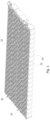
- FIG. 1 representatively illustrates an exploded schematic view of a battery pack
- the battery pack includes four battery sets, each battery sets includes a battery connection module 20 proposed by the present disclosure and a battery cell array (AR1-AR4).
- a person skilled in the art easily understands that, in order to apply relevant design of the present disclosure to other types of energy storing devices, various modifications, additions, substitutions, deletions or other variations may be made to following specific embodiments, but these modifications, additions, substitutions, deletions or other variations are still fallen within a scope of a principle of the battery connection module 20 proposed by the present disclosure.
- each battery connection module 20 respectively have a first end portion busbar 80 and a second end portion busbar 82, each component of the first end portion busbar 80 respectively connects negative electrodes of battery cells 24 of one end of the two ends of the corresponding battery cell array of the battery connection module 20, each component of the second end portion busbar 82 respectively connects positive electrodes of battery cells 24 of the other end of the two ends of the battery cell array.
- four battery connection modules 20 may be alternately arranged and be reversed relative to each other.
- FIG. 2 illustrates a partial structure of a right end of FIG. 1 , taking a sequence from lower left to upper right in FIG.
- FIG. 3 illustrates a partial structure of a left end of FIG.
- the second end portion busbar 82 of the first battery connection module 20 is connected to the positive electrodes of the battery cells 24 of a left end of the battery cell array AR1
- the first end portion busbar 80 of the second battery connection module 20 is connected to the negative electrodes of the battery cells 24 of a left end of the battery cell array AR2
- the second end portion busbar 82 of the third battery connection module 20 is connected to the positive electrodes of the battery cells 24 of a left end of the battery cell array AR3
- the first end portion busbar 80 of the fourth battery connection module 20 is connected to the negative electrodes of the battery cells 24 of a left end of the battery cell array AR4.
- the battery pack further includes an inputting busbar 78, an outputting busbar 114, a first bridging busbar 44, a second bridging busbar 48 and a third bridging busbar 52.
- the inputting busbar 78 is connected to the first end portion busbar 80 of the battery connection module 20 which corresponds to the battery cell array AR1
- the inputting busbar 78 is provided with a first power connector 26 (that is, a negative electrode end)
- the outputting busbar 114 is connected to the second end portion busbar 82 of the battery connection module 20 which corresponds to the battery cell array AR4
- the outputting busbar 114 is provided with a second power connector 28 (that is, a positive electrode end)
- the first bridging busbar 44 is connected to the second end portion busbar 82 of the battery connection module 20 which corresponds to the battery cell array AR2 and the first end portion busbar 80 of the battery connection module 20 which corresponds to the battery cell array AR3
- the second bridging busbar 48 is connected to the second end portion busbar 82 of the battery connection module 20 which corresponds to the battery cell array AR1 and the first end portion busbar 80 of the battery connection module 20 which corresponds to the battery cell array AR2,
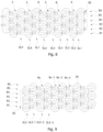
- the battery connection module 20 proposed by the present disclosure is used to connect the battery cell array, the battery cells 24 are arranged side by side in columns (CL1-CLX) and rows (R1-RX), the battery cells 24 of every two adjacent columns are offset and staggered relative to each other, and the battery cells 24 of every two adjacent rows are offset and staggered relative to each other.
- the corresponding battery cell 24 of one column of the two adjacent columns is positioned between the corresponding two battery cells 24 of the other column of the two adjacent columns
- the corresponding battery cell 24 of one row of the two adjacent rows is positioned between the two battery cells 24 of the other row of the two adjacent rows.
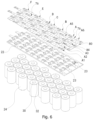
- Each battery cell 24 has the positive electrode and the negative electrode which are in the same end face, for example, a positive electrode terminal 30 and a negative electrode terminal 32 as shown in FIG. 6 .
- the battery connection module 20 includes a tray 22 and a plurality of connecting busbars A.
- each connecting busbar A has a plurality of components (A1-A6).
- Each of a part (A2, A4-A6) of the plurality of components has a main body portion 60, a positive electrode connecting portion 62 which extends from a first end of the main body portion 60 and a negative electrode connecting portion 64 which extends from a second end of the main body portion 60.
- the positive electrode connecting portion 62 is connected to the positive electrode of one corresponding battery cell 24, the negative electrode connecting portion 64 is connected to the negative electrode of one corresponding battery cell 24.
- Each of a part (A3) of the plurality of components has a main body portion 60 and only has a positive electrode connecting portion 62 which extends from a first end of the main body portion 60.
- Each of a part (A1) of the plurality of components has a main body portion 60 and only has a negative electrode connecting portion 64 which extends from a second end of the main body portion 60.
- the main body portions 60 of the plurality of components (A1-A6) of the connecting busbar A are correspondingly connected therebetween via respective connection portions 58.
- each connecting busbar A at least one component connects the positive electrode and the negative electrode of the two battery cells 24 of every other column, at least one component connects the positive electrode and the negative electrode of the two battery cells 24 of the same row, at least one component only connects the positive electrode of one battery cell 24, at least one component only connects the negative electrode of one battery cell 24.
- the battery connection module 20 proposed by the present disclosure can be adapted to the battery cell array in which the battery cells 24 are irregularly arranged, each battery cell 24 of the battery cell array has the positive electrode and the negative electrode which are in the same end face, the battery cells 24 of every two adjacent columns are staggered in the corresponding rows so that the battery cells 24 forms a regular symmetric arrangement, in such a type of the battery cell array, by the battery connection module 20 promoted by the present disclosure, it can use one connecting busbar A to realize connection with more number of the battery cells 24, can connect the battery cells 24 which are not positioned in regular symmetric positions, at the same time can use a plurality of connecting busbars A which each has a different irregular symmetric configuration to connect the battery cells 24.
- the main body portion 60 is a plane structure and extends linearly.
- a thickness of the positive electrode connecting portion 62 is less than a thickness of the main body portion 60, a lower surface of the positive electrode connecting portion 62 is coplanar with a lower surface of the main body portion 60.
- a middle of the negative electrode connecting portion 64 of each of the part (A1-A2, A4-A6) of the plurality of components the connecting busbar is provided with a slit to form two branching feet 65, the two branching feet 65 also may be a splayed construction, or the negative electrode connecting portion 64 also may form three or more branching feet 65.
- the negative electrode connecting portion 64 has a first part 66, a second part 68 and a third part 70.
- the first part 66 extends from the main body portion 60 and is coplanar with the main body portion 60
- the second part 68 extends downwardly and obliquely from the first part 66 by an angle
- the third part 70 extends from second part 68 by an angle and is parallel to the first part 66
- the third part 70 is used to connect the negative electrode of the corresponding battery cell 24.
- the main body portion 60 of each component (A1-A6) of the connecting busbar A is provided with a fusible portion 63 which acts as overcurrent protection, a cross sectional area of the fusible portion 63 in a thickness direction is minimum relative to a cross sectional area of the other part of the main body portion 60, so that the fusible portion 63 has high resistance, can generate large heat and can be melted and interrupted under overcurrent.
- the main body portion 60 is provided with a material removed portion 61 close to the positive electrode connecting portion 62 and the fusible portion 63 is constructed by the material removed portion 61.
- the material removed portion 61 may be a groove, a through hole and the like, in addition, the material removed portion 61 also may be provided with at least two different types of thinning structures so as to construct the fusible portion 63 on the main body portion 60, for example, the through hole and the groove and the like are provided at the same time.
- the fusible portion 63 provided at a position of the main body portion 60 close to the negative electrode connecting portion 64 is taken as an example for description, in some embodiments, the fusible portion 63 also may be provided at a position of the main body portion 60 close to the positive electrode connecting portion 62, or is provided at other position of the main body portion 60, and the present disclosure is not limited thereto.
- the material removed portion 61 may be an aperture constructed on the main body portion 60, and two edge strips which are at two opposite sides of the aperture together constitute the fusible portion 63, the two edge strips are constructed as V-shapes which protrude toward each other and toward an interior of the aperture.
- the tray 22 is integrally provided with an assembling post 23, the connecting busbar A is provided with an assembling hole 76 which corresponds to the assembling post 23.
- the connecting busbar A and the tray 22 are assembled by means of the assembling post 23 and the assembling hole 76 which cooperate with each other.
- a part of an end of the assembling post 23 passing through the assembling hole 76 is connected with the connecting busbar A by hot melting or riveting.
- the one battery cell array may be longer in length, so a plurality of trays 22 may be provided, that is, the tray 22 may be one or plurality in number, and when the tray 22 is provided as plurality, adjacent trays 22 may connected together (for example but is not limited to employ an integral structure).
- each column of the battery cell array has Y battery cells 24 and is the same in the number of battery cells 24, each connecting busbar A includes X positive electrode connecting portions 62 and X negative electrode connecting portions 64, and X is larger than Y.
- each column of the battery cell array of the present embodiment includes three battery cells, so that six rows (R1-R6) of the battery cells are constituted in the battery cell array, the plurality of connecting busbars are arranged to repeat a group that six connecting busbars (A-F) having different structure features are continuously arranged so that a plurality of groups is formed to connect the battery cells, each connecting busbar has six components, five positive electrode connecting portions and five negative electrode connecting portions.
- Each connecting busbar spans the battery cells of four columns and connects ten battery cells 24 of the battery cells (the five positive electrode connecting portions respectively connect the positive electrodes of five battery cells and the five negative electrode connecting portions respectively connect the negative electrodes of additional five battery cells).
- the plurality of connecting busbars A are divided to a plurality of groups which repeatedly arrange one of the plurality of groups, each group includes at least two connecting busbars A, the connecting busbars A of the same group are not completely the same in structure feature.
- the above structure feature includes at least one of a position, an extending length, a width, a relative angle of the main body portion 60, the positive electrode connecting portion 62, the negative electrode connecting portion 64 and the connecting portion 58 of any component (A1-A6) of the connecting busbar A.
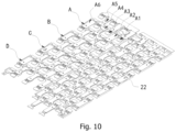
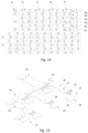
- FIG. 10 representatively illustrates a perspective view of a partial structure of the battery connection module in another exemplary embodiment which conforms to the principle of the present disclosure with a partial structure of the trays 22 and the connecting busbars A of the battery connection module shown
- FIG. 11 representatively illustrates an exploded schematic view of FIG. 10
- FIG. 12 representatively illustrates a partially enlarged schematic view of FIG. 11 indicated by a dotted-line frame P
- FIG. 13 representatively illustrates a partially enlarged schematic view of FIG. 11 indicated by a dotted-line frame Q
- FIG. 14 representatively illustrates a plane schematic view of the connecting busbars A of the battery connection module of FIG. 10 and FIG. 11
- FIG. 15 representatively illustrates a perspective view of one connecting busbar A of the battery connection module of FIG. 10 and FIG. 11 .
- the fusible portion 63 is provided between the main body portion 60 and the positive electrode connecting portion 62.
- each connecting strip there is at least one connecting strip between the main body portion 60 and the positive electrode connecting portion 62, the connecting strip constitutes the fusible portion 63, the connecting strip is constructed as an arch which protrudes.
- the connecting strip is constructed as an arch which protrudes.
- FIG. 14 and FIG. 15 there is an aperture 69 between the main body portion 60 and the positive electrode connecting portion 62, the two connecting strips which are positioned at two opposite sides of the aperture 69 respectively constitute the fusible portions 63, each connecting strip constitutes an arch which protrudes upwardly relative to the main body portion 60 and the positive electrode connecting portion 62.
- the shape of the arch of the fusible portion 63 may allow a position of the positive electrode connecting portion 62 to have movable elasticity so that the position of the positive electrode connecting portion 62 may have relative large movement so as to be connected to the positive electrode of the corresponding battery cell (for example assembling position tolerance), and the fusible portion 63 can endure relative movement between the positive electrode connecting portion 62 and the main body portion 60 (for example relative movement resulted from vibration).
- the two adjacent trays 22 are connected by a connecting construction
- the connecting construction includes a latching piece which is provided to one of the two adjacent trays 22 and a latching block which is provided to the other of the two adjacent trays 22.
- the latching piece 221 is constructed as a pair of latching legs, tips of two latching legs have latching hooks 222 which face each other.
- the latching block is constituted as a T-shaped protruding block 223.
- each component, which has the negative electrode connecting portion 64, of the plurality of components of the connecting busbar A makes the negative electrode connecting portion 64 constituted as an arc-shaped sheet body which spreads toward two sides.
- step portion 67 which is between the main body portion 60 and the negative electrode connecting portion 64 and bends downwardly.
- the battery connection module proposed by the present disclosure can be adapted to the battery cell array in which the battery cells are irregularly arranged, each battery cell of the battery cell array has the positive electrode and the negative electrode which are in the same end face, the battery cells of every two adjacent columns are staggered in the corresponding rows so that the battery cells forms a regular symmetric arrangement, in such a type of the battery cell array, by the battery connection module promoted by the present disclosure, it can use one connecting busbar to realize connection with more number of the battery cells, can connect the battery cells which are not positioned in regular symmetric positions, at the same time can use a plurality of connecting busbars which each has a different irregular symmetric configuration to connect the battery cells.
- the exemplary embodiments of the battery connection module proposed by the present disclosure are described and/or illustrated in detail above.
- the embodiments of the present disclosure are not limited to the specific embodiments described herein.
- the components and/or steps of each embodiment can be used independently and separately from other components and/or steps described herein.
- Each component and/or step of one embodiment may also be used in combination with other components and/or steps of other embodiments.
- the terms "one”, “a/an” and “the above” are used to indicate the existence of one or more elements/components/etc.
Landscapes
- Chemical & Material Sciences (AREA)
- Chemical Kinetics & Catalysis (AREA)
- Electrochemistry (AREA)
- General Chemical & Material Sciences (AREA)
- Connection Of Batteries Or Terminals (AREA)
- Battery Mounting, Suspending (AREA)
Applications Claiming Priority (2)
| Application Number | Priority Date | Filing Date | Title |
|---|---|---|---|
| CN202210176845 | 2022-02-25 | ||
| CN202310021961.XA CN116666912A (zh) | 2022-02-25 | 2023-01-06 | 电池连接模组 |
Publications (1)
| Publication Number | Publication Date |
|---|---|
| EP4235941A1 true EP4235941A1 (fr) | 2023-08-30 |
Family
ID=85227375
Family Applications (1)
| Application Number | Title | Priority Date | Filing Date |
|---|---|---|---|
| EP23156316.4A Pending EP4235941A1 (fr) | 2022-02-25 | 2023-02-13 | Module de connexion de batterie |
Country Status (3)
| Country | Link |
|---|---|
| EP (1) | EP4235941A1 (fr) |
| JP (1) | JP7705423B2 (fr) |
| KR (1) | KR102943617B1 (fr) |
Cited By (6)
| Publication number | Priority date | Publication date | Assignee | Title |
|---|---|---|---|---|
| WO2025108765A1 (fr) * | 2023-11-24 | 2025-05-30 | Elringklinger Ag | Module et/ou bloc, et système de batterie fabriqué à partir de celui-ci |
| EP4567980A1 (fr) | 2023-12-07 | 2025-06-11 | Röchling Automotive SE | Système de mise en contact de cellules et batterie dotée d'un système de mise en contact de cellules |
| EP4539240A3 (fr) * | 2023-10-11 | 2025-06-18 | Eve Power Co., Ltd. | Ensemble barre omnibus, module de batterie et bloc-batterie |
| EP4601105A1 (fr) * | 2024-02-07 | 2025-08-13 | LG Energy Solution, Ltd. | Bloc-batterie et véhicule le comprenant |
| WO2025195710A1 (fr) * | 2024-03-18 | 2025-09-25 | John Deere Electric Powertrain Llc | Dispositif de mise en contact électrique de cellules de batterie |
| DE102024128967A1 (de) * | 2024-10-08 | 2026-04-09 | Bayerische Motoren Werke Aktiengesellschaft | Batteriezellanordnung für einen Hochvoltspeicher |
Families Citing this family (2)
| Publication number | Priority date | Publication date | Assignee | Title |
|---|---|---|---|---|
| US20250300311A1 (en) * | 2024-08-15 | 2025-09-25 | Shenzhen Hello Tech Energy Co., Ltd | Energy storage power supply |
| WO2026063028A1 (fr) * | 2024-09-20 | 2026-03-26 | パナソニックIpマネジメント株式会社 | Module de batterie |
Citations (4)
| Publication number | Priority date | Publication date | Assignee | Title |
|---|---|---|---|---|
| TWI308406B (fr) | 2005-02-04 | 2009-04-01 | Li-Han Yao | |
| US20170256770A1 (en) * | 2016-03-01 | 2017-09-07 | Atieva, Inc. | Battery Pack Bus Bar Assembly with Shaped Interconnect Mounting Platforms |
| EP3790074A2 (fr) * | 2019-09-09 | 2021-03-10 | Samsung SDI Co., Ltd. | Bloc-batterie |
| KR20220001989A (ko) * | 2020-06-30 | 2022-01-06 | 주식회사 엘지에너지솔루션 | 배터리 모듈, 그것을 포함하는 배터리 팩, 및 자동차 |
Family Cites Families (13)
| Publication number | Priority date | Publication date | Assignee | Title |
|---|---|---|---|---|
| CN101180749B (zh) | 2005-05-23 | 2011-04-13 | 松下电器产业株式会社 | 电池模块及其制造方法 |
| JP5992694B2 (ja) | 2012-02-23 | 2016-09-14 | 矢崎総業株式会社 | 電線配索装置 |
| CN104737328B (zh) | 2012-10-26 | 2017-03-08 | 三洋电机株式会社 | 电源装置以及具备电源装置的电动车辆及蓄电装置、电源装置的制造方法 |
| KR102272264B1 (ko) | 2014-01-20 | 2021-07-02 | 삼성에스디아이 주식회사 | 단락 연결부를 갖는 전지 모듈 |
| KR101792820B1 (ko) * | 2014-12-22 | 2017-11-01 | 주식회사 엘지화학 | 파단 유도부가 형성된 단자 접속부재 및 댐핑부재를 포함하는 전지팩 |
| CN106531945B (zh) | 2015-09-12 | 2023-04-18 | 宁德时代新能源科技股份有限公司 | 并联电池模组 |
| JP6861376B2 (ja) | 2016-05-31 | 2021-04-21 | パナソニックIpマネジメント株式会社 | 端子接続構造、電池積層体及び端子接続構造の形成方法 |
| US11824226B2 (en) | 2018-09-26 | 2023-11-21 | Panasonic Intellectual Property Management Co., Ltd. | Battery module |
| CN114128033B (zh) | 2019-10-11 | 2024-06-28 | 株式会社Lg新能源 | 包括汇流条板的电池模块、包括电池模块的电池组及电子装置 |
| CN112310560B (zh) | 2019-10-21 | 2021-11-12 | 宁德时代新能源科技股份有限公司 | 连接组件、电池模块、电池组以及使用电池模块作为电源的设备 |
| KR102924578B1 (ko) | 2020-02-26 | 2026-02-05 | 엘지전자 주식회사 | 배터리 팩 |
| EP3872891A1 (fr) | 2020-02-27 | 2021-09-01 | Mersen France Angers SAS | Barre omnibus stratifiée pour dispositif de stockage d'énergie |
| CN213845448U (zh) | 2020-12-30 | 2021-07-30 | 内蒙古稀奥科镍氢动力电池有限公司 | 一种镍氢电池焊接片 |
-
2023
- 2023-02-13 EP EP23156316.4A patent/EP4235941A1/fr active Pending
- 2023-02-14 JP JP2023020627A patent/JP7705423B2/ja active Active
- 2023-02-24 KR KR1020230024782A patent/KR102943617B1/ko active Active
Patent Citations (5)
| Publication number | Priority date | Publication date | Assignee | Title |
|---|---|---|---|---|
| TWI308406B (fr) | 2005-02-04 | 2009-04-01 | Li-Han Yao | |
| US7811701B2 (en) | 2005-02-04 | 2010-10-12 | Li-Ho Yao | Battery assembly |
| US20170256770A1 (en) * | 2016-03-01 | 2017-09-07 | Atieva, Inc. | Battery Pack Bus Bar Assembly with Shaped Interconnect Mounting Platforms |
| EP3790074A2 (fr) * | 2019-09-09 | 2021-03-10 | Samsung SDI Co., Ltd. | Bloc-batterie |
| KR20220001989A (ko) * | 2020-06-30 | 2022-01-06 | 주식회사 엘지에너지솔루션 | 배터리 모듈, 그것을 포함하는 배터리 팩, 및 자동차 |
Cited By (6)
| Publication number | Priority date | Publication date | Assignee | Title |
|---|---|---|---|---|
| EP4539240A3 (fr) * | 2023-10-11 | 2025-06-18 | Eve Power Co., Ltd. | Ensemble barre omnibus, module de batterie et bloc-batterie |
| WO2025108765A1 (fr) * | 2023-11-24 | 2025-05-30 | Elringklinger Ag | Module et/ou bloc, et système de batterie fabriqué à partir de celui-ci |
| EP4567980A1 (fr) | 2023-12-07 | 2025-06-11 | Röchling Automotive SE | Système de mise en contact de cellules et batterie dotée d'un système de mise en contact de cellules |
| EP4601105A1 (fr) * | 2024-02-07 | 2025-08-13 | LG Energy Solution, Ltd. | Bloc-batterie et véhicule le comprenant |
| WO2025195710A1 (fr) * | 2024-03-18 | 2025-09-25 | John Deere Electric Powertrain Llc | Dispositif de mise en contact électrique de cellules de batterie |
| DE102024128967A1 (de) * | 2024-10-08 | 2026-04-09 | Bayerische Motoren Werke Aktiengesellschaft | Batteriezellanordnung für einen Hochvoltspeicher |
Also Published As
| Publication number | Publication date |
|---|---|
| JP2023124825A (ja) | 2023-09-06 |
| KR20230127923A (ko) | 2023-09-01 |
| JP7705423B2 (ja) | 2025-07-09 |
| KR102943617B1 (ko) | 2026-03-26 |
Similar Documents
| Publication | Publication Date | Title |
|---|---|---|
| EP4235941A1 (fr) | Module de connexion de batterie | |
| JP7212504B2 (ja) | 接続モジュール | |
| KR101494463B1 (ko) | 배터리의 단자의 전기 접속 시스템 및 방법 | |
| CN115732830A (zh) | 电池连接模组及电池组 | |
| US9812694B2 (en) | Electrode member and battery block | |
| JP6226868B2 (ja) | セルスタック用セル電圧モニタリング・コネクタシステム | |
| CN104821383B (zh) | 电池组件 | |
| KR100542238B1 (ko) | 전지 모듈 | |
| CN109792025B (zh) | 连接模块 | |
| CA2242220A1 (fr) | Element de fusible a plusieurs electrodes et fusible a plusieurs electrodes employant cet element | |
| US20090208837A1 (en) | Method of electrically connecting cell terminals in a battery pack | |
| CA2589890A1 (fr) | Element de liaison de borne d'un module de batterie secondaire | |
| RU98112332A (ru) | Плавкий элемент многоэлектродного типа и плавкий предохранитель многоэлектродного типа (варианты) | |
| US9537190B2 (en) | Battery cell separators | |
| DE102015206248B4 (de) | Batteriezellentrenner | |
| JP6536314B2 (ja) | 配線モジュール | |
| WO2018061826A1 (fr) | Module de connexion | |
| KR20230134345A (ko) | 배터리모듈용 직렬연결장치 및 이를 포함하는 배터리조립체 | |
| US2983778A (en) | Battery clip | |
| ES2627413T3 (es) | Chapa de resorte de contacto y batería electroquímica con una chapa de resorte de contacto de este tipo | |
| CN107431162B (zh) | 电池组 | |
| US20230066953A1 (en) | Battery module for electric passenger vehicle | |
| CN116666912A (zh) | 电池连接模组 | |
| JP7055613B2 (ja) | 組電池 | |
| CN218414947U (zh) | 电池连接结构、电池模组及电池包 |
Legal Events
| Date | Code | Title | Description |
|---|---|---|---|
| PUAI | Public reference made under article 153(3) epc to a published international application that has entered the european phase |
Free format text: ORIGINAL CODE: 0009012 |
|
| STAA | Information on the status of an ep patent application or granted ep patent |
Free format text: STATUS: THE APPLICATION HAS BEEN PUBLISHED |
|
| AK | Designated contracting states |
Kind code of ref document: A1 Designated state(s): AL AT BE BG CH CY CZ DE DK EE ES FI FR GB GR HR HU IE IS IT LI LT LU LV MC ME MK MT NL NO PL PT RO RS SE SI SK SM TR |
|
| STAA | Information on the status of an ep patent application or granted ep patent |
Free format text: STATUS: REQUEST FOR EXAMINATION WAS MADE |
|
| 17P | Request for examination filed |
Effective date: 20231005 |
|
| P01 | Opt-out of the competence of the unified patent court (upc) registered |
Effective date: 20230928 |
|
| RBV | Designated contracting states (corrected) |
Designated state(s): AL AT BE BG CH CY CZ DE DK EE ES FI FR GB GR HR HU IE IS IT LI LT LU LV MC ME MK MT NL NO PL PT RO RS SE SI SK SM TR |
|
| STAA | Information on the status of an ep patent application or granted ep patent |
Free format text: STATUS: EXAMINATION IS IN PROGRESS |
|
| 17Q | First examination report despatched |
Effective date: 20240214 |