EP4235976A2 - Connecteur enfichable comprenant un pont conducteur de protection - Google Patents
Connecteur enfichable comprenant un pont conducteur de protection Download PDFInfo
- Publication number
- EP4235976A2 EP4235976A2 EP23175513.3A EP23175513A EP4235976A2 EP 4235976 A2 EP4235976 A2 EP 4235976A2 EP 23175513 A EP23175513 A EP 23175513A EP 4235976 A2 EP4235976 A2 EP 4235976A2
- Authority
- EP
- European Patent Office
- Prior art keywords
- connector
- protective conductor
- housing
- designed
- bridge
- Prior art date
- Legal status (The legal status is an assumption and is not a legal conclusion. Google has not performed a legal analysis and makes no representation as to the accuracy of the status listed.)
- Granted
Links
Images



Classifications
-
- H—ELECTRICITY
- H01—ELECTRIC ELEMENTS
- H01R—ELECTRICALLY-CONDUCTIVE CONNECTIONS; STRUCTURAL ASSOCIATIONS OF A PLURALITY OF MUTUALLY-INSULATED ELECTRICAL CONNECTING ELEMENTS; COUPLING DEVICES; CURRENT COLLECTORS
- H01R13/00—Details of coupling devices of the kinds covered by groups H01R12/70 or H01R24/00 - H01R33/00
- H01R13/648—Protective earth or shield arrangements on coupling devices, e.g. anti-static shielding
- H01R13/655—Protective earth or shield arrangements on coupling devices, e.g. anti-static shielding with earth brace
-
- H—ELECTRICITY
- H01—ELECTRIC ELEMENTS
- H01R—ELECTRICALLY-CONDUCTIVE CONNECTIONS; STRUCTURAL ASSOCIATIONS OF A PLURALITY OF MUTUALLY-INSULATED ELECTRICAL CONNECTING ELEMENTS; COUPLING DEVICES; CURRENT COLLECTORS
- H01R13/00—Details of coupling devices of the kinds covered by groups H01R12/70 or H01R24/00 - H01R33/00
- H01R13/40—Securing contact members in or to a base or case; Insulating of contact members
- H01R13/42—Securing in a demountable manner
- H01R13/428—Securing in a demountable manner by resilient locking means on the contact members; by locking means on resilient contact members
- H01R13/432—Securing in a demountable manner by resilient locking means on the contact members; by locking means on resilient contact members by stamped-out resilient tongue snapping behind shoulder in base or case
-
- H—ELECTRICITY
- H01—ELECTRIC ELEMENTS
- H01R—ELECTRICALLY-CONDUCTIVE CONNECTIONS; STRUCTURAL ASSOCIATIONS OF A PLURALITY OF MUTUALLY-INSULATED ELECTRICAL CONNECTING ELEMENTS; COUPLING DEVICES; CURRENT COLLECTORS
- H01R13/00—Details of coupling devices of the kinds covered by groups H01R12/70 or H01R24/00 - H01R33/00
- H01R13/46—Bases; Cases
- H01R13/502—Bases; Cases composed of different pieces
-
- H—ELECTRICITY
- H01—ELECTRIC ELEMENTS
- H01R—ELECTRICALLY-CONDUCTIVE CONNECTIONS; STRUCTURAL ASSOCIATIONS OF A PLURALITY OF MUTUALLY-INSULATED ELECTRICAL CONNECTING ELEMENTS; COUPLING DEVICES; CURRENT COLLECTORS
- H01R13/00—Details of coupling devices of the kinds covered by groups H01R12/70 or H01R24/00 - H01R33/00
- H01R13/46—Bases; Cases
- H01R13/502—Bases; Cases composed of different pieces
- H01R13/512—Bases; Cases composed of different pieces assembled by screw or screws
-
- H—ELECTRICITY
- H01—ELECTRIC ELEMENTS
- H01R—ELECTRICALLY-CONDUCTIVE CONNECTIONS; STRUCTURAL ASSOCIATIONS OF A PLURALITY OF MUTUALLY-INSULATED ELECTRICAL CONNECTING ELEMENTS; COUPLING DEVICES; CURRENT COLLECTORS
- H01R13/00—Details of coupling devices of the kinds covered by groups H01R12/70 or H01R24/00 - H01R33/00
- H01R13/46—Bases; Cases
- H01R13/516—Means for holding or embracing insulating body, e.g. casing, hoods
-
- H—ELECTRICITY
- H01—ELECTRIC ELEMENTS
- H01R—ELECTRICALLY-CONDUCTIVE CONNECTIONS; STRUCTURAL ASSOCIATIONS OF A PLURALITY OF MUTUALLY-INSULATED ELECTRICAL CONNECTING ELEMENTS; COUPLING DEVICES; CURRENT COLLECTORS
- H01R13/00—Details of coupling devices of the kinds covered by groups H01R12/70 or H01R24/00 - H01R33/00
- H01R13/46—Bases; Cases
- H01R13/53—Bases or cases for heavy duty; Bases or cases for high voltage with means for preventing corona or arcing
-
- H—ELECTRICITY
- H01—ELECTRIC ELEMENTS
- H01R—ELECTRICALLY-CONDUCTIVE CONNECTIONS; STRUCTURAL ASSOCIATIONS OF A PLURALITY OF MUTUALLY-INSULATED ELECTRICAL CONNECTING ELEMENTS; COUPLING DEVICES; CURRENT COLLECTORS
- H01R24/00—Two-part coupling devices, or either of their cooperating parts, characterised by their overall structure
- H01R24/20—Coupling parts carrying sockets, clips or analogous contacts and secured only to wire or cable
- H01R24/22—Coupling parts carrying sockets, clips or analogous contacts and secured only to wire or cable with additional earth or shield contacts
-
- H—ELECTRICITY
- H01—ELECTRIC ELEMENTS
- H01R—ELECTRICALLY-CONDUCTIVE CONNECTIONS; STRUCTURAL ASSOCIATIONS OF A PLURALITY OF MUTUALLY-INSULATED ELECTRICAL CONNECTING ELEMENTS; COUPLING DEVICES; CURRENT COLLECTORS
- H01R24/00—Two-part coupling devices, or either of their cooperating parts, characterised by their overall structure
- H01R24/28—Coupling parts carrying pins, blades or analogous contacts and secured only to wire or cable
- H01R24/30—Coupling parts carrying pins, blades or analogous contacts and secured only to wire or cable with additional earth or shield contacts
Definitions
- the present invention relates to a connector for mechanical and electrical connection to a corresponding mating connector, comprising a housing, a protective conductor bridge and a plug insert, the protective conductor bridge being held on the housing.
- Such connectors and mating connectors are used in the prior art to create an electrical and mechanical connection between two electrical lines or an electrical line and a device or an installation.
- Large, heavy connectors, which are protected against environmental influences by the housing, are required in particular for the transmission of large currents.
- Such housings are usually made of aluminum and are provided with a thread for receiving a cable gland.
- the connectors considered here are designed to connect a number of electrical conductors, one of which is a protective conductor (PE contact).
- the protective conductor can also be combined with a neutral conductor as a PEN contact.
- the protective conductor is connected to the protective conductor bridge to enable a corresponding protective conductor function and to bring the protective conductors of the connector and mating connector into contact with one another.
- the remaining conductors are connected to electrical contacts of the plug insert.
- the basic structure of the connector and mating connector can be essentially identical and only differ in the configuration of their electrical contacts for establishing the electrical connection differentiate.
- the explanations for the connector therefore apply accordingly to the mating connector.
- Plug connectors and mating connectors are designed correspondingly according to the plug-socket principle for establishing an electrical connection between the plug connector and the mating connector.
- the electrical contacts of the connector and mating connector can each be designed as contact pins or contact pin receptacles.
- the connector insert is firmly positioned on the housing for a secure electrical connection between the conductors of the connector and mating connector.
- a disadvantage of the plug connector described above is that the assembly of the protective conductor bridge and the plug insert is complex and assembly space must be kept free in the housing in order to assemble both the plug insert and the protective conductor bridge. As a result, it is necessary to design the connector to be correspondingly large. In addition, such connectors are often heavy, which makes them difficult to handle.
- the invention is therefore based on the object of specifying a connector of the type mentioned above that is simple and cost-effective to produce, easy to handle and enables a secure mechanical and electrical connection of connector and mating connector.
- a connector for mechanical and electrical connection with a corresponding mating connector comprising a housing, a protective conductor bridge and a plug insert, the protective conductor bridge being held on the housing, the protective conductor bridge having at least one connection area for connection to the plug insert, and the plug insert is held on the at least one connection area.
- the basic idea of the present invention is therefore to simplify the assembly of the connector by the protective conductor bridge being mounted in and directly on the housing and the plug insert being mounted in the housing directly on the protective conductor bridge.
- the protective conductor bridge is first attached separately to the housing, and in a further assembly step the plug insert is attached to the already installed protective conductor bridge.
- the connector formed in this way is easy to assemble and requires little space for installation. As a result, the weight of the connector is also low.
- the assembly of the plug insert is independent of the order in which the plug insert and protective conductor bridge are inserted into the housing.
- the plug connector is designed in such a way that the plug insert is first mounted on the protective conductor bridge and the unit formed in this way can then be mounted together in the housing.
- Protective conductor bridge and contacts of the plug insert are connected to individual conductors, for example individual conductors of a cable to be connected, with the protective conductor bridge being connected to a protective conductor, also PE conductor. More ladder are connected to electrical contacts of the plug insert.
- the plug insert can be designed to contact the mating connector with contact pins or corresponding receptacles for the contact pins, or with any other corresponding contacts.
- the plug connector and the mating connector can thus be designed either as a male or female plug according to the plug-socket principle, without this requiring a difference for the assembly of the plug insert or the protective conductor bridge according to the invention.
- the protective conductor can also be designed as a PEN contact with an integrated neutral conductor.
- the explanations for the connector apply accordingly to the mating connector.
- the protective conductor bridge is suitable for reliably attaching the plug insert, since it is designed as an electrical conductor and is therefore usually made of metal.
- the protective conductor bridge thus has a high level of stability, resulting in a robust and reliable connector.
- the plug connector is designed in such a way that the at least one connection area is designed to produce a screw connection with the plug insert.
- the screw connection enables the plug insert to be attached to the protective conductor bridge in a stable and reliable manner.
- the connection area for producing the screw connection are possible, for example the connection area can have a bolt with an external thread for screwing on the plug insert. A screw can also be held at the connection area.
- the connector is designed in such a way that the at least one connection area has a through hole.
- the through hole allows a connecting screw or a screw bolt to be passed through, so that the plug insert and the protective conductor bridge can be fastened to one another, producing a screw connection.
- the connector is designed in such a way that the through-hole is designed with an internal thread.
- the internal thread enables a screw to be screwed in directly, so that the plug insert can be attached to the protective conductor bridge in a simple manner and using only at least one screw with a corresponding external thread.
- the connector is designed in such a way that the at least one connection area is made of sheet metal.
- the sheet metal has a high level of stability, as a result of which the plug insert is reliably held on the protective conductor bridge and thus on the housing.
- the connector is designed in such a way that the at least one connection area is designed with a tubular body.
- the tubular body has high strength for attachment of the plug insert.
- the attachment can be, for example, on an outer wall of the tubular body or on the tubular body take place overall.
- the tubular configuration can be formed by simply bending or folding the sheet metal.
- the tubular body is preferably designed with a substantially rectangular cross-section. It is further preferred that the connection area is designed as a hollow body.
- the connector is designed in such a way that the tubular body has two opposite through holes, and one of the through holes is designed with an internal thread.
- the two opposed through holes allow fasteners to pass through to attach the plug insert to the connection area. Due to the internal thread, a screw can be used to fasten the plug insert, while the second threaded through hole is only used for guidance.
- the hollow space between the through-holes creates a spring effect, so that the plug insert is screwed reliably and securely to the protective conductor bridge.
- the connector is designed in such a way that the through-hole with the internal thread is designed with a passage.
- the passage makes it possible to provide a threaded area with a greater thread length and a higher number of threads than is the case with the through hole alone.
- the connection area is made of sheet metal
- the material thickness of the sheet metal usually results in a short thread length, which can be increased by drawing through.
- the passage is possible
- the connecting area made of sheet metal it can easily be produced from the sheet metal by appropriately forming the through-hole.
- the passage can be attached to the sheet metal as a separate component, for example by welding, soldering or other joining techniques.
- the plug connector is designed in such a way that the protective conductor bridge has two connection areas that are formed on its axial end areas.
- the two connection areas result in a reliable and durable attachment of the plug insert to the protective conductor bridge.
- the protective conductor bridge can be stretched over the connection areas through the plug insert, so that it is not subject to the risk of deformation.
- the connection areas are preferably formed at the end areas in the longitudinal axis of the protective conductor bridge.
- the plug connector is designed in such a way that the protective conductor bridge has an elongate bridge main body, and the at least one connection region is formed laterally on the bridge main body.
- the protective conductor bridge can be attached, for example, along a wall of the housing, and the connection areas can protrude from the protective conductor bridge into an interior space of the housing. This allows the plug insert to be easily attached to the protective conductor bridge.
- the protective conductor bridge and the connection areas are particularly preferably arranged at a substantially right angle to one another.
- the bridge main body can have its smallest thickness in an insertion direction of the mating connector, while the connecting portion protrudes into the housing perpendicularly thereto, to be able to easily and reliably attach the connector plug thereto.
- the protective conductor bridge is made of an elastic material, such as metal, the bridge main body is elastically connected to the connection area, which facilitates the assembly of the connector because tolerances can be easily compensated.
- the mobility of the bridge main body in relation to the connection area facilitates the insertion. Tilting when inserting this unit into the housing can be prevented or compensated for.
- the connector is designed in such a way that the at least one connection area has fastening means for connecting the protective conductor bridge to the housing.
- the fastening means can be designed as desired, for example in the form of a through opening with or without an internal thread for screwing the protective conductor bridge to the housing at the connection areas.
- a through hole is formed in the connection portion for connecting the plug insert and the housing to the protective conductor bridge at the same time.
- the fastening means are designed to create a non-positive or positive connection of the protective conductor bridge to the housing. For example, at least a connection portion having a spring tab to establish a frictional connection with the housing.
- the connector is designed in such a way that the fastening means are designed as latching means in order to latch with corresponding latching means of the housing.
- the latching means enable the protective conductor bridge to be easily attached to the housing. To remove the protective conductor jumper from the housing, the latching can be canceled again in a simple manner.
- the latching means can be designed, for example, as latching lugs or tongues.
- a latching tab is particularly preferably formed on the connection area.
- the housing preferably has a guide groove with a latching lug into which the latching tongue can be inserted and latched therein.
- the plug connector is designed such that the housing has a plug opening with two opposite sides, and a protective conductor bridge is attached to each of the two opposite sides, the plug insert being held together on both protective conductor bridges.
- This configuration of the plug connector makes it possible to reliably hold even a large plug insert in the housing, since support is provided on the opposite sides of the housing via the two protective conductor bridges. It also facilitates the assembly of a plug insert and protective conductor bridge unit in the housing, since this unit can be easily inserted between the opposite sides. With a conical configuration of the housing and/or a corresponding angling of the protective conductor bridges, this unit can be introduced into the housing in a self-centering manner.
- the connector can also be designed in such a way that it is rotationally symmetrical, ie it can be connected identically to the mating connector when rotated through 180° about the axis of the insertion direction of the mating connector.
- the connector is designed in such a way that the protective conductor bridge is made in one piece from sheet metal.
- the construction from sheet metal enables a protective conductor bridge to be produced using little material, the sheet metal being easy to shape, for example by bending, folding or the like, in order to shape the at least one connection area.
- the connector is designed in such a way that the housing is made of plastic.
- the housing can be made of plastic with a reduced weight, which makes the connector easy to handle.
- the plastic provides electrical insulation, which makes the connector easier to use and increases safety.
- the connector 1 shows a connector 1 according to the invention according to a first embodiment of the invention.
- the connector 1 includes a housing 2, two protective conductor bridges 3, only one of which in the 1 is visible, and a plug insert, not shown here.
- the protective conductor bridges 3 and the plug insert are fixed in the housing 2, it being possible, for example, for electrical contacts of the plug insert to protrude from the housing 2.
- the housing 2 is made of plastic using the injection molding process and is designed with a cable gland 4 that is molded on.
- the cable gland 4 is used to guide a cable with a plurality of conductors into the housing 2 .
- One of the conductors is a protective conductor, which is connected to the protective conductor bridge 3, also known as the PE conductor.
- the further conductors are connected to electrical contacts of the plug insert.
- the plug insert is designed for contacting a corresponding mating connector, not shown here, with contact pins or corresponding receptacles for contact pins.
- the housing 2 has a plug opening 5, via which the connector 1 can be electrically and mechanically connected to the corresponding mating connector.
- the connector opening 5 is rectangular, with two opposite sides 6 of the connector opening 5, here the longitudinal sides, being arranged parallel to one another.
- the protective conductor bridges 3 are fitted in the housing 2 along the longitudinal sides 6 .
- the protective conductor bridge 3 off 2 is made in one piece from sheet metal and comprises an elongate bridge main body 7, at the axial end areas 8 of which a connecting area 9 is formed in each case.
- the connection portions 9 are laterally positioned on a common side on the bridge main body 7 .
- the connecting regions 9 are designed with a tubular body 10 which has a rectangular cross section.
- the tubular body 10 of the connection areas 9 is formed in each case by bending the metal sheet of the protective conductor bridges 3 in the area of the connection areas 9 .
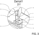
- the tubular body 10 has two opposite through holes 11, 12, as shown in detail in FIG 3 is shown. That in the 3 Through hole 11 shown above is designed as a through hole without an internal thread, while in FIG 3 shown lower through hole 12 is designed with a passage 13, wherein the lower through hole 12 and the passage 13 have an internal thread.
- the plug insert can be mounted on the connecting areas 9 of the protective conductor bridges 3 by means of four screws (not shown), the screws being guided through the upper through-hole 11 and being screwed into the lower through-hole 12 with the passage 13 .
- a latching lug 14 is also formed on each of the connecting regions 9, with which the protective conductor bridge 3 is latched at its axial end regions 8 in a guide groove 15 behind a latching projection 16 of the housing 2, as shown in detail in FIG 3 is shown.
- the protective conductor bridges 3 can each be inserted alone or as a unit with the plug insert through the plug opening 5 into the housing 2 and assembled by establishing the latching connection.
- the protective conductor bridge 3 of the second embodiment essentially corresponds to the protective conductor bridge 3 of the first embodiment, so that it can be used in exchange for the protective conductor bridge 3 of the first embodiment in the housing 2 described with reference to the first embodiment.
- similar elements are denoted by the same reference numbers. Since the protective conductor bridges 3 of the second embodiment essentially correspond to those of the first embodiment agree, only their differences will be discussed here.
- the protective conductor bridge 3 of the second embodiment differs from that of the first embodiment in the design of its connection areas 9.
- the connection areas 9 of the protective conductor bridge 3 of the second embodiment each have a bottom area 17.
- the sheet metal of the connecting areas 9 is bent upwards at the edges of the bottom area 17 in order to form a locking lug 14 and side walls 18 as described above.
- In the bottom area 17 there is also a through hole 12 with a passage 13 as previously described, which has a corresponding internal thread.
- Reference List connector 1 Housing 2 protective conductor bridge 3 cable gland 4 connector opening 5 Opposite sides, long sides 6 bridge main body 7 end area 8th connection area 9 tubular body 10 upper through hole 11 lower through hole 12 Draft 13 locking flag, fasteners 14 guide groove 15 locking lug, locking means 16 floor area 17 Side wall 18
Landscapes
- Details Of Connecting Devices For Male And Female Coupling (AREA)
- Connector Housings Or Holding Contact Members (AREA)
Applications Claiming Priority (4)
| Application Number | Priority Date | Filing Date | Title |
|---|---|---|---|
| DE102012101813A DE102012101813B3 (de) | 2012-03-05 | 2012-03-05 | Steckverbinder |
| PCT/EP2013/054410 WO2013131918A1 (fr) | 2012-03-05 | 2013-03-05 | Fiche de raccordement avec pontet de conducteur de protection |
| EP20204687.6A EP3796482B1 (fr) | 2012-03-05 | 2013-03-05 | Connecteur enfichable comprenant un pont conducteur de protection |
| EP13714560.3A EP2823536B1 (fr) | 2012-03-05 | 2013-03-05 | Fiche de raccordement avec pontet de conducteur de protection |
Related Parent Applications (2)
| Application Number | Title | Priority Date | Filing Date |
|---|---|---|---|
| EP20204687.6A Division EP3796482B1 (fr) | 2012-03-05 | 2013-03-05 | Connecteur enfichable comprenant un pont conducteur de protection |
| EP13714560.3A Division EP2823536B1 (fr) | 2012-03-05 | 2013-03-05 | Fiche de raccordement avec pontet de conducteur de protection |
Publications (3)
| Publication Number | Publication Date |
|---|---|
| EP4235976A2 true EP4235976A2 (fr) | 2023-08-30 |
| EP4235976A3 EP4235976A3 (fr) | 2023-09-20 |
| EP4235976B1 EP4235976B1 (fr) | 2026-04-29 |
Family
ID=48049945
Family Applications (3)
| Application Number | Title | Priority Date | Filing Date |
|---|---|---|---|
| EP13714560.3A Active EP2823536B1 (fr) | 2012-03-05 | 2013-03-05 | Fiche de raccordement avec pontet de conducteur de protection |
| EP23175513.3A Active EP4235976B1 (fr) | 2012-03-05 | 2013-03-05 | Connecteur enfichable comprenant un pont conducteur de protection |
| EP20204687.6A Active EP3796482B1 (fr) | 2012-03-05 | 2013-03-05 | Connecteur enfichable comprenant un pont conducteur de protection |
Family Applications Before (1)
| Application Number | Title | Priority Date | Filing Date |
|---|---|---|---|
| EP13714560.3A Active EP2823536B1 (fr) | 2012-03-05 | 2013-03-05 | Fiche de raccordement avec pontet de conducteur de protection |
Family Applications After (1)
| Application Number | Title | Priority Date | Filing Date |
|---|---|---|---|
| EP20204687.6A Active EP3796482B1 (fr) | 2012-03-05 | 2013-03-05 | Connecteur enfichable comprenant un pont conducteur de protection |
Country Status (6)
| Country | Link |
|---|---|
| US (1) | US9368919B2 (fr) |
| EP (3) | EP2823536B1 (fr) |
| JP (2) | JP2015509651A (fr) |
| CN (1) | CN104254949B (fr) |
| DE (5) | DE102012101813B3 (fr) |
| WO (1) | WO2013131918A1 (fr) |
Families Citing this family (9)
| Publication number | Priority date | Publication date | Assignee | Title |
|---|---|---|---|---|
| DE102012101813B3 (de) | 2012-03-05 | 2013-06-13 | Phoenix Contact Gmbh & Co. Kg | Steckverbinder |
| USD744968S1 (en) * | 2013-03-19 | 2015-12-08 | Phoenix Contact Gmbh & Co. Kg | Electrical housing |
| DE102014109351B3 (de) | 2014-07-04 | 2015-07-30 | Harting Electric Gmbh & Co. Kg | Steckverbinder mit Schutzleiterbrücke |
| USD820787S1 (en) * | 2016-08-02 | 2018-06-19 | Robert Bosch Gmbh | Connection plug |
| DE102017102223B3 (de) | 2017-02-06 | 2018-07-19 | Harting Electric Gmbh & Co. Kg | Steckverbinder mit Schutzleiterbrücke |
| USD1054381S1 (en) * | 2019-10-29 | 2024-12-17 | Enconnex LLC | Base power connector housing |
| USD1021803S1 (en) * | 2019-10-29 | 2024-04-09 | Enconnex LLC | Power connector housing |
| USD969765S1 (en) * | 2020-08-13 | 2022-11-15 | Virginia Panel Corporation | Interface device |
| DE102023118401A1 (de) | 2023-07-12 | 2025-01-16 | Harting Electric Stiftung & Co. Kg | Verbindungselement, Steckverbindergehäusesystem, Steckverbinder und Steckverbindersystem |
Family Cites Families (20)
| Publication number | Priority date | Publication date | Assignee | Title |
|---|---|---|---|---|
| US3566336A (en) * | 1968-08-30 | 1971-02-23 | Itt | Connector assembly |
| DE2033011B2 (de) * | 1970-07-03 | 1974-12-05 | Bayerische Elektrozubehoer H. Schlutius Kg, 8560 Lauf | Schutzkontaktstecker |
| DE2330633A1 (de) | 1973-06-15 | 1975-01-09 | Bunker Ramo | Elektrischer steckverbinder |
| SE402676B (sv) | 1976-04-30 | 1978-07-10 | Olsson Gunnar | Elektrisk honkontakt av typen, ingjutningskontakt |
| US4688868A (en) * | 1986-05-14 | 1987-08-25 | Honeywell Information Systems Inc. | Grounding gasket for D-shell connector |
| NL8902192A (nl) * | 1989-08-30 | 1991-03-18 | Du Pont Nederland | Inbouwconnector voorzien van een vergrendelframe. |
| US5234357A (en) * | 1990-07-04 | 1993-08-10 | Hirose Electric Co., Ltd. | Lock mechanism for electrical connector |
| US5603639A (en) * | 1995-08-30 | 1997-02-18 | Genrife Company Limited | Shielded electrical connector |
| DE29602740U1 (de) | 1996-02-21 | 1996-04-11 | Phoenix Contact GmbH & Co, 32825 Blomberg | Elektrischer Steckverbinder |
| DE29908490U1 (de) | 1999-05-12 | 1999-08-05 | Contact GmbH Elektrische Bauteile, 70565 Stuttgart | Haltesystem für verschiedene Typen Steckverbinder |
| JP2003036942A (ja) * | 2001-07-23 | 2003-02-07 | Sumitomo Wiring Syst Ltd | コネクタ |
| DE102004048770B4 (de) * | 2004-10-05 | 2007-11-29 | Phoenix Contact Gmbh & Co. Kg | Gehäuseanordnung mit mindestens zwei Verbindungsdosen |
| DE102005019245B3 (de) * | 2005-04-26 | 2007-03-01 | Pc Electric Ges. M.B.H. | Optimierte Anschließbarkeit durch axiales Rasten von elektrischen Steckvorrichtungen |
| US8288651B2 (en) * | 2007-09-28 | 2012-10-16 | Kenneth Smith | Weatherproof connector |
| DE202007017892U1 (de) | 2007-12-21 | 2008-03-20 | Harting Electric Gmbh & Co. Kg | Steckverbinder mit PE-Blech |
| JP4916031B2 (ja) * | 2008-07-31 | 2012-04-11 | 第一電子工業株式会社 | 固定具及び該固定具を用いた電気コネクタ |
| DE102009055925B4 (de) * | 2009-11-27 | 2017-08-03 | Phoenix Contact Gmbh & Co. Kg | Steckverbinderanordnung |
| KR101355749B1 (ko) | 2009-12-09 | 2014-02-04 | 하르팅 에렉트릭 게엠베하 운트 코우. 카게 | 시스템 플러그 커넥터 |
| DE102010017717B4 (de) | 2010-07-02 | 2014-06-05 | Phoenix Contact Gmbh & Co. Kg | Steckverbinder |
| DE102012101813B3 (de) | 2012-03-05 | 2013-06-13 | Phoenix Contact Gmbh & Co. Kg | Steckverbinder |
-
2012
- 2012-03-05 DE DE102012101813A patent/DE102012101813B3/de not_active Revoked
-
2013
- 2013-03-05 DE DE202013012813.5U patent/DE202013012813U1/de not_active Expired - Lifetime
- 2013-03-05 EP EP13714560.3A patent/EP2823536B1/fr active Active
- 2013-03-05 DE DE202013012815.1U patent/DE202013012815U1/de not_active Expired - Lifetime
- 2013-03-05 DE DE202013012817.8U patent/DE202013012817U1/de not_active Expired - Lifetime
- 2013-03-05 EP EP23175513.3A patent/EP4235976B1/fr active Active
- 2013-03-05 US US14/383,097 patent/US9368919B2/en not_active Expired - Fee Related
- 2013-03-05 CN CN201380011896.7A patent/CN104254949B/zh active Active
- 2013-03-05 WO PCT/EP2013/054410 patent/WO2013131918A1/fr not_active Ceased
- 2013-03-05 JP JP2014560337A patent/JP2015509651A/ja active Pending
- 2013-03-05 DE DE202013012812.7U patent/DE202013012812U1/de not_active Expired - Lifetime
- 2013-03-05 EP EP20204687.6A patent/EP3796482B1/fr active Active
-
2016
- 2016-06-13 JP JP2016117198A patent/JP6174759B2/ja not_active Expired - Fee Related
Also Published As
| Publication number | Publication date |
|---|---|
| US20150024621A1 (en) | 2015-01-22 |
| DE202013012815U1 (de) | 2020-02-27 |
| US9368919B2 (en) | 2016-06-14 |
| WO2013131918A1 (fr) | 2013-09-12 |
| EP4235976A3 (fr) | 2023-09-20 |
| JP2016186940A (ja) | 2016-10-27 |
| DE202013012812U1 (de) | 2020-02-27 |
| JP2015509651A (ja) | 2015-03-30 |
| CN104254949B (zh) | 2017-11-24 |
| JP6174759B2 (ja) | 2017-08-02 |
| EP3796482B1 (fr) | 2023-05-31 |
| EP2823536A1 (fr) | 2015-01-14 |
| DE202013012817U1 (de) | 2020-02-27 |
| DE202013012813U1 (de) | 2020-02-27 |
| DE102012101813B3 (de) | 2013-06-13 |
| EP3796482A1 (fr) | 2021-03-24 |
| CN104254949A (zh) | 2014-12-31 |
| EP4235976B1 (fr) | 2026-04-29 |
| EP2823536B1 (fr) | 2020-12-23 |
Similar Documents
| Publication | Publication Date | Title |
|---|---|---|
| EP3796482B1 (fr) | Connecteur enfichable comprenant un pont conducteur de protection | |
| DE102013113975C5 (de) | Halterahmen für einen Steckverbinder | |
| DE60209288T2 (de) | Semipermanente Verbindung zwischen einer Stromschiene und einem Verbinderkontakt | |
| DE102013011216B3 (de) | Trennbare Steckvorrichtung | |
| DE102014109351B3 (de) | Steckverbinder mit Schutzleiterbrücke | |
| DE202013104784U1 (de) | Reihenbausteinanordnung mit einem Energiebussystem | |
| DE102020110979A1 (de) | Steckverbinder einer elektrischen Steckverbindung sowie damit gebildete elektrische Steckverbindung | |
| WO2012000597A1 (fr) | Connecteur par enfichage pourvu d'un blindage sous forme d'un conducteur externe | |
| DE102018213986B4 (de) | Elektrischer Verbindungskasten | |
| EP2580823A1 (fr) | Connecteur enfichable rapporté | |
| EP4014287A1 (fr) | Connecteur femelle de carte de circuit imprimé xlr à 8+2 voies | |
| EP4500637A1 (fr) | Module de mise à la terre destiné à être reçu dans un cadre modulaire de connecteur à fiche métallique et qui met à la terre ledit cadre modulaire | |
| DE102005059990A1 (de) | Steckverbinder zur Verbindung elektronischer Bauelemente | |
| EP3891849A1 (fr) | Boîtier d'adaptateur pour un élément de contact destiné à la fixation sur un profilé chapeau | |
| DE202004015082U1 (de) | Einheit zur Installation einer elektrischen Leitung | |
| DE9014856U1 (de) | Isolierkörper für elektrische Kontakte | |
| DE202017107625U1 (de) | Elektrischer Steckverbinder | |
| EP3577725B1 (fr) | Connecteur enfichable équipé d'un pont de connexion de conducteurs de protection | |
| EP0600207A1 (fr) | Connecteur | |
| EP2262062B1 (fr) | Connecteur à fiches | |
| DE202013104941U1 (de) | Elektrische Steckverbinderanordnung und Schirmanbindungselement hierzu | |
| DE4236844A1 (de) | Anschlußklemme | |
| WO2024245492A1 (fr) | Appareil de fixation pour unités fonctionnelles d'un module de connecteur enfichable multifonctionnel, module de connecteur enfichable multifonctionnel et système modulaire de connecteur enfichable | |
| DE10031428A1 (de) | Elektrische Anschlußklemme | |
| DE102013106767A1 (de) | Klemme für PE- oder Schutzleiter |
Legal Events
| Date | Code | Title | Description |
|---|---|---|---|
| PUAI | Public reference made under article 153(3) epc to a published international application that has entered the european phase |
Free format text: ORIGINAL CODE: 0009012 |
|
| STAA | Information on the status of an ep patent application or granted ep patent |
Free format text: STATUS: THE APPLICATION HAS BEEN PUBLISHED |
|
| REG | Reference to a national code |
Ref legal event code: R079 Ipc: H01R0013655000 Ref country code: DE Ref legal event code: R079 Ref document number: 502013016625 Country of ref document: DE Free format text: PREVIOUS MAIN CLASS: H01R0013432000 Ipc: H01R0013655000 |
|
| PUAL | Search report despatched |
Free format text: ORIGINAL CODE: 0009013 |
|
| AC | Divisional application: reference to earlier application |
Ref document number: 2823536 Country of ref document: EP Kind code of ref document: P Ref document number: 3796482 Country of ref document: EP Kind code of ref document: P |
|
| AK | Designated contracting states |
Kind code of ref document: A2 Designated state(s): AL AT BE BG CH CY CZ DE DK EE ES FI FR GB GR HR HU IE IS IT LI LT LU LV MC MK MT NL NO PL PT RO RS SE SI SK SM TR |
|
| AK | Designated contracting states |
Kind code of ref document: A3 Designated state(s): AL AT BE BG CH CY CZ DE DK EE ES FI FR GB GR HR HU IE IS IT LI LT LU LV MC MK MT NL NO PL PT RO RS SE SI SK SM TR |
|
| RIC1 | Information provided on ipc code assigned before grant |
Ipc: H01R 24/22 20110101ALN20230816BHEP Ipc: H01R 13/53 20060101ALN20230816BHEP Ipc: H01R 13/512 20060101ALN20230816BHEP Ipc: H01R 13/516 20060101ALN20230816BHEP Ipc: H01R 13/432 20060101ALI20230816BHEP Ipc: H01R 13/655 20060101AFI20230816BHEP |
|
| STAA | Information on the status of an ep patent application or granted ep patent |
Free format text: STATUS: REQUEST FOR EXAMINATION WAS MADE |
|
| 17P | Request for examination filed |
Effective date: 20240318 |
|
| RBV | Designated contracting states (corrected) |
Designated state(s): AL AT BE BG CH CY CZ DE DK EE ES FI FR GB GR HR HU IE IS IT LI LT LU LV MC MK MT NL NO PL PT RO RS SE SI SK SM TR |
|
| GRAP | Despatch of communication of intention to grant a patent |
Free format text: ORIGINAL CODE: EPIDOSNIGR1 |
|
| STAA | Information on the status of an ep patent application or granted ep patent |
Free format text: STATUS: GRANT OF PATENT IS INTENDED |
|
| RIC1 | Information provided on ipc code assigned before grant |
Ipc: H01R 13/655 20060101AFI20250922BHEP Ipc: H01R 13/432 20060101ALI20250922BHEP Ipc: H01R 13/516 20060101ALN20250922BHEP Ipc: H01R 13/512 20060101ALN20250922BHEP Ipc: H01R 13/53 20060101ALN20250922BHEP Ipc: H01R 24/22 20110101ALN20250922BHEP |
|
| INTG | Intention to grant announced |
Effective date: 20251002 |
|
| P01 | Opt-out of the competence of the unified patent court (upc) registered |
Free format text: CASE NUMBER: UPC_APP_0014140_4235976/2025 Effective date: 20251120 |
|
| GRAS | Grant fee paid |
Free format text: ORIGINAL CODE: EPIDOSNIGR3 |
|
| GRAA | (expected) grant |
Free format text: ORIGINAL CODE: 0009210 |
|
| STAA | Information on the status of an ep patent application or granted ep patent |
Free format text: STATUS: THE PATENT HAS BEEN GRANTED |
|
| AC | Divisional application: reference to earlier application |
Ref document number: 3796482 Country of ref document: EP Kind code of ref document: P Ref document number: 2823536 Country of ref document: EP Kind code of ref document: P |
|
| AK | Designated contracting states |
Kind code of ref document: B1 Designated state(s): AL AT BE BG CH CY CZ DE DK EE ES FI FR GB GR HR HU IE IS IT LI LT LU LV MC MK MT NL NO PL PT RO RS SE SI SK SM TR |
|
| REG | Reference to a national code |
Ref country code: CH Ref legal event code: F10 Free format text: ST27 STATUS EVENT CODE: U-0-0-F10-F00 (AS PROVIDED BY THE NATIONAL OFFICE) Effective date: 20260429 |