EP4235981A1 - Câble adaptateur et procédé de fonctionnement de composants de système électronique - Google Patents
Câble adaptateur et procédé de fonctionnement de composants de système électronique Download PDFInfo
- Publication number
- EP4235981A1 EP4235981A1 EP23153013.0A EP23153013A EP4235981A1 EP 4235981 A1 EP4235981 A1 EP 4235981A1 EP 23153013 A EP23153013 A EP 23153013A EP 4235981 A1 EP4235981 A1 EP 4235981A1
- Authority
- EP
- European Patent Office
- Prior art keywords
- data
- conversion
- cable
- adapter cable
- communication systems
- Prior art date
- Legal status (The legal status is an assumption and is not a legal conclusion. Google has not performed a legal analysis and makes no representation as to the accuracy of the status listed.)
- Pending
Links
Images


Classifications
-
- H—ELECTRICITY
- H01—ELECTRIC ELEMENTS
- H01R—ELECTRICALLY-CONDUCTIVE CONNECTIONS; STRUCTURAL ASSOCIATIONS OF A PLURALITY OF MUTUALLY-INSULATED ELECTRICAL CONNECTING ELEMENTS; COUPLING DEVICES; CURRENT COLLECTORS
- H01R31/00—Coupling parts supported only by co-operation with counterpart
- H01R31/06—Intermediate parts for linking two coupling parts, e.g. adapter
- H01R31/065—Intermediate parts for linking two coupling parts, e.g. adapter with built-in electric apparatus
-
- H—ELECTRICITY
- H04—ELECTRIC COMMUNICATION TECHNIQUE
- H04L—TRANSMISSION OF DIGITAL INFORMATION, e.g. TELEGRAPHIC COMMUNICATION
- H04L12/00—Data switching networks
- H04L12/02—Details
- H04L12/10—Current supply arrangements
Definitions
- the present invention relates to an adapter cable according to the preamble of claim 1 and a method for operating electronic system components according to the preamble of claim 10.
- connection element such as a connection socket
- connection elements In the field of data bus technology, such as PoDL (Power over Data Line), SPE (Single Pair Ethernet), TPE (Twisted Pair Ethernet), asynchronous connection elements are also known, the associated connection elements according to different standards, such as the IEC 60603- 7-5, are trained.
- Embodiments of fasteners that take up this standard are, for example, from DE 10 2017 101 544 B3 known, which discloses a connecting element with a locking element which is held on a fixed bearing and a floating bearing.
- a comparable connecting element is from the DE 10 2019 131 596 B3 known, in which an advantageous, secure form-fitting connection with the counter-connection element is made possible by the connecting element.
- This interface converter is housed in a housing and has a printed circuit board with electronic circuits inside the housing. These are configured in such a way that data signals can be converted from a host device transmission medium to a second transmission medium.
- a connector which comprises in the connector body one or more electronic components with an integrated circuit which is programmed with identification and configuration information about the connector. These can be communicated to a device while connecting.
- the circuitry may include or participate in a so-called handshake algorithm that communicates the function of one or more contacts to a host device to which the connector is connected.
- a disadvantage of the previously known solutions is that the wide variety of possible connecting elements for the operators of existing systems and production processes that already use a special data bus system require complex converters for data and/or power supply when combined with an alternative bus system. It is also very complex for manufacturers of electronic components, since the large number of possible system combinations requires extensive warehousing and/or installation space for the electronic components.
- Another disadvantage is that the known, rigid adapters only offer a mechanically unstable solution. The adapter must continue to be created anew when changing the coupling or it must also be completely replaced.
- first or second “connecting element” means a finger- or pin-like connector or a socket-like connector.
- the present invention is not limited to the design of the respective connecting element.
- contact element means the respective associated central data- and current-conducting element, whereby a finger, pin or socket contact element can also be meant here, unless something specific is explicitly stated.
- the required conversion electronics are divided into two components or functional connectors and connected with a two- or multi-wire connection cable.
- a third Communication system formed, which is both different in terms of the signals exchanged to the first and the second communication system.
- the signals running through the wires of the connecting cable do not correspond to any of the connected communication types or their standard signals in an identical manner, but differ by at least one feature, such as data format/speed, line type, number and /or division of the transmission wires etc.
- an SPE data signal in a connection element can only be separated from its DC component, with the actual coding remaining the same and not being further converted.
- signal is to be understood as meaning data, measurement and information signals of any kind and electrical current or electrical power.
- a further improved embodiment of the adapter cable consists in the fact that the first and the second conversion unit of the first and the second connection element complement each other (completely) for the purpose of a complete data and/or power conversion for two communication systems. This means that each element required for converting the signals between the first and the second communication system is simply provided on or on one of the conversion units, and they only represent a fully functional conversion unit together with the respectively required wires of the connecting cable.
- the first and the second conversion unit of the first and the second connecting element each include a PHY, a microprocessor unit (CPU) and a DC converter, which are defined by the possibly standardized (standardized) connector.
- the connection element with an IOL plug/contact also has an IOL PHY
- a connection element with a (standard) SPE plug/contact element has an SPE-PHY
- a connection element with a CAN plug/contact element has a CAN-PHY.
- a further improved embodiment of the adapter cable is that a physical sensor is arranged on or in at least one of the connector bodies, which transmits data to one of the conversion units and at least one of the electronic components there is connected, with the measured values and/or data of the physical sensor being convertible by the conversion units in such a way that they can be transmitted to at least one, ideally to both, communication systems.
- the physical sensor means that a physical value or a physical quantity can be measured, such as temperature (temperature sensor), mechanical influences (shock sensor, inclination and/or vibration sensor), current flow (current sensor) or an approach or contact ( proximity sensor, e.g. inductive proximity sensor).
- a data acquisition unit is arranged on or in at least one of the connector bodies, which is connected in a data-conducting manner to one of the conversion units and at least one of the electronic components there, the measured and acquired data values of the data acquisition unit being convertible by the conversion units in this way are that they can be transmitted to at least one of the communication systems, ideally to both.
- the data acquisition unit is designed and used to acquire data-relevant measured values and variables, for example the amount of data transmitted, transmission direction/sequence and/or their clocking, with these being acquired independently of the connected electronic system components.
- one of the existing electronic components of a conversion unit can receive the measurement data and/or values and convert (translate) and forward them in a suitable manner for at least one of the two communication systems, with a Microprocessor unit is involved in organizing.
- an additional PHY or circuit PCB
- PCB PHY or circuit
- a storage medium is provided in a connector body and/or on one of the conversion units, in which the measurement data and/or measurement values can be stored at least temporarily.
- a further improved embodiment of the adapter cable can be that the contact element of the respective connecting element and / or the connector body are standardized, according to the respective communication system, the connector body and the associated contact elements as plug fingers or Socket can be formed, the contact elements are standardized in particular according to one of the sub-norms of DIN IEC 63171-x or 611131-x.
- the first conversion element of the first connection element comprises or represents a current converter, in particular a direct current converter and an oscillation converter
- the second conversion element of the second connection element comprises or represents a data converter, in particular a first physical layer (PHY) of the first communication system and a second physical layer (PHY) of the second communication system, and in particular a microprocessor unit ( ⁇ C) connected and organized therewith.
- PHY physical layer
- PHY microprocessor unit
- the PHY (physical layer) is a hardware component with at least one integrated circuit. It forms the connecting element or interface between a physical medium such as a plug and/or a connecting cable on the one hand and the digital data on the other.
- a PHY typically includes a Physical Medium Attachment (PMA) sublayer, a Forward Error Correction (FEC) sublayer, and a Physical Coding sublayer (PCS).
- PMA Physical Medium Attachment
- FEC Forward Error Correction
- PCS Physical Coding sublayer
- This embodiment can be further improved in that the second conversion element of the second connection element comprises a further voltage converter which is correlated with the voltage level of the second communication system or defined by it, and the further voltage converter being connected to the voltage converter of the first via at least two wires of the connecting cable Conversion element is directly connected.
- At least one of the conversion units includes an analog-to-digital converter (ADC).
- ADC analog-to-digital converter
- the invention also includes a method for operating electronic system components from two different communication systems, which are in particular two standardized communication systems (data bus, fieldbus), such as a serial CAN bus, an SPE or an IO-Link (IOL).
- two standardized communication systems data bus, fieldbus
- serial CAN bus serial CAN bus
- SPE serial CAN bus
- IOL IO-Link
- an adapter cable as a connection between two electronic Provided system components that are assigned to one of the two communication systems and are designed according to their standards and / or norms and work.
- the adapter cable is designed according to at least one of the aforementioned embodiments.
- a first part of the conversion of the signals takes place on or in the first connection element and the second part of the conversion of the signals takes place on or in the second connection element.
- this is designed in such a way that in one connection element the conversion of the electrical power and/or separation of the frequency or amplitude applied to the current and relating to the data transmission takes place, with the actual data (information) being converted on the other connection element will, according to the respective data protocols.
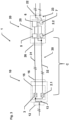
- the figure 1 shows a schematic structure of an adapter cable 1 for the current and data-conducting connection of two electronic system components 4.1, 4.2, which originate from two different communication systems A, B, with the left system component 4.1, for example, belonging to an SPE communication system A and the right electronic system component 4.2 e.g. to an IO-Link Communication system B belongs.
- the two system components 4.1, 4.2 are sketched as dashed lines.
- first connecting element 10 is an SPE connector standardized according to DIN IEC 63171-5 and the second connecting element 20 is an IOL connector standardized according to DIN 611131-9, with no distinction being made here between socket and plug-in finger.
- the first connecting element 10 has a plug-in end 10.1 and a cable end 10.2, and the second connecting element in an analogous manner also has a plug-in end 20.1 and a cable end 20.2.
- the multi-core connecting cable 30 connects the two connecting elements 10, 20 to one another for current and data transmission and is inserted into the respective plug body 11, 21 at the two cable ends 10.2, 20.2. Furthermore, contact elements 12, 22 are provided, via which the actual forwarding of current and/or data takes place by wire or phase, and a cable entry 16, 26 for the respective end of the connecting cable 30.
- the left plug body 10 has an external thread, not shown and is designed overall, for example, as a dust and moisture-proof connector of protection class PJ 67.
- the right-hand connector body 20 has a union nut as the connecting element and is designed, for example, as an M8 connector for IO-Link.
- the first connecting element 10 has a first conversion unit 15 in the form of a printed circuit board, which is connected to the contact element 13 via the (inner) connecting line 13 .
- the conversion unit 15 is connected to the cable entry 16 via the (inner) connecting line 14 .
- the contact element 12 or the contact element 22 is fastened directly on or to the respective circuit board, in particular soldered, and/or the respective cable entry is made directly on or to the circuit board, without an (internal) connecting line arranged in between.
- the electronic components arranged on the circuit board or the conversion unit 15 are described below by way of example, also in connection with FIG 2 explained.
- the second connecting element 20 has a second conversion unit 25, and the connecting line 23 is connected to the contact element 22 in a current-conducting and data-conducting manner.
- a connecting line 24 to the cable entry 26 is provided on the opposite side.
- the first conversion unit 15 of the left, first connecting element 10 is designed for current or power conversion and includes the corresponding electronic components, as in FIG 2 shown closer.
- the left, second conversion unit 25 of the second connection element 20 is designed and includes appropriate electronic components in order to carry out the data conversion and protocol adaptation.
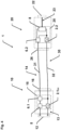
- the figure 2 shows more details about figure 1 and clearly shows the asymmetrical structure of the adapter cable 1.
- a voltage converter 2 and a vibration converter 3 are arranged on the conversion unit 15 in the left, first connecting element 10 .
- the conversion of SPE data (PoDL) into performance data takes place via the voltage converter 2 (direct current) and the oscillation component that is independent of this and represents the data stream via the oscillation converter 3.
- These signals are transmitted via two two-wire cores 31 , 32 to the conversion element 25 or to an IOL PHY 7 there and/or a microprocessor unit 6 (microprocessor unit), where the transfer to the IOL protocol is carried out.
- the data coming in from the IOL system component which comes in, for example, via a three-wire line or a three-pole contact on the contact element 22, is converted into the SPE protocol in the SPE PHY 5 and the microprocessor unit 6 and in particular to the only two DC veins imprinted.
- FIG 3 is another variant analogous to figure 2 shown by a first voltage converter 2.1 being provided on the first conversion unit 15, and different from the 2
- An additional direct-current converter 2.2 is provided in the second connecting element 20, with which, for example, a voltage different from the SPE communication system A can be provided or a power loss over a longer connecting cable 30 can be compensated.
- the DC converter 2.2 continues to supply the microprocessor unit 6 and the IO-PHY 7 with voltage.
- the upper pole is a two-wire power connection (PWR) and the lower pole is intended for the single-wire data line (C/Q).
- the first connecting element 10 is provided for connection to a serial CAN bus and the contact element 12 is designed with 4 poles in the example shown, with two wires being connected to a CAN PHY 5 and two wires leading from the corresponding poles to the first DC converter 2.1. Furthermore, a first microprocessor unit 6.1 (CPU) is also provided on the conversion element 15 of the first connecting element 10 .
- the second connecting element 20 is used to connect to a system component 4.2 (not shown), for example, which is designed as a simple, terminal sensor and transmits analog measured values. This system component 4.2 can have its own additional power supply and a further DC converter 2.2.
- the second conversion element 25 of the second connecting element 20 also has an analog-to-digital converter 8 (ADC) and a further microprocessor unit 6.2 connected thereto for organizing the ADC 8.
- ADC analog-to-digital converter 8
- the second, further microprocessor unit 6.2 is optional here.
- the entire organization of the data streams and/or protocol conversion can also take place using just one microprocessor unit 6 .
- each connecting element has a CPU which primarily organizes the data on the respective connection side, ie on the connector end 19.1, 20.1.
- the two direct-current converters 2.1, 2.2 are connected to one another via the 2-wire core group 32, while the two microprocessor units 6.1, 6.2 are connected via a 1- to 3-wire core group 31.
- the number of wires in wire group 31 depends on the respective system protocol, with a OneWire only requiring one wire or wire, a Universal Asynchronous Receiver Transmitter (UART) requiring a 2-wire connection and a Serial Peripheral Interface interface ( SPI interface) three- or four-wire connections can be implemented.
- the first connecting element 10 not having a contact element 12 for a CAN bus connection, but for a standard IOL, and on the conversion unit correspondingly an IOL PHY 5 and a standardized 3-wire contact element 12.
- the wire group 32 between the DC converters 2.1, 2.2 is also designed with 2 wires and, if necessary, shielded alone or together with the 1 to 3-wire core group 31.
Landscapes
- Engineering & Computer Science (AREA)
- Computer Networks & Wireless Communication (AREA)
- Signal Processing (AREA)
- Communication Control (AREA)
Applications Claiming Priority (1)
| Application Number | Priority Date | Filing Date | Title |
|---|---|---|---|
| DE102022104522.6A DE102022104522A1 (de) | 2022-02-25 | 2022-02-25 | Adapterkabel und Verfahren zum Betrieb von elektronischen Systemkomponenten |
Publications (1)
| Publication Number | Publication Date |
|---|---|
| EP4235981A1 true EP4235981A1 (fr) | 2023-08-30 |
Family
ID=85076467
Family Applications (1)
| Application Number | Title | Priority Date | Filing Date |
|---|---|---|---|
| EP23153013.0A Pending EP4235981A1 (fr) | 2022-02-25 | 2023-01-24 | Câble adaptateur et procédé de fonctionnement de composants de système électronique |
Country Status (2)
| Country | Link |
|---|---|
| EP (1) | EP4235981A1 (fr) |
| DE (1) | DE102022104522A1 (fr) |
Families Citing this family (1)
| Publication number | Priority date | Publication date | Assignee | Title |
|---|---|---|---|---|
| DE102024120269A1 (de) * | 2024-07-18 | 2026-01-22 | Ifm Electronic Gmbh | Adapter zur Einbindung eines Feldgeräts in eine SPE-Umgebung |
Citations (8)
| Publication number | Priority date | Publication date | Assignee | Title |
|---|---|---|---|---|
| US1164821A (en) | 1912-01-04 | 1915-12-21 | S O & C Co | Manufacture of celluloid-covered articles. |
| US6386919B2 (en) * | 1998-04-22 | 2002-05-14 | Stratos Lightwave, Inc. | High speed interface converter module |
| EP2290877B1 (fr) * | 2009-08-28 | 2012-12-05 | Astrium GmbH | Agencement de liaison à bus de données |
| DE102013207940A1 (de) | 2012-09-07 | 2014-03-13 | Apple Inc. | Steckverbindermodule |
| EP2359441B1 (fr) | 2008-12-19 | 2014-04-09 | Telegärtner Karl Gärtner Gmbh | Connecteur électrique |
| DE102017101544A1 (de) | 2017-01-26 | 2018-07-26 | Refratechnik Holding Gmbh | Tragelement für einen Tunnelofenwagen oder -schlitten, Tunnelofenwagen oder -schlitten mit derartigen Tragelementen sowie Tunnelofen mit einem derartigen Tunnelofenwagen oder -schlitten |
| DE102019131596B3 (de) | 2019-11-22 | 2021-01-28 | Telegärtner Karl Gärtner GmbH | Steckverbinder |
| US20210382253A1 (en) | 2018-10-17 | 2021-12-09 | Samsung Electronics Co., Ltd. | Cable device |
Family Cites Families (8)
| Publication number | Priority date | Publication date | Assignee | Title |
|---|---|---|---|---|
| JPH0221580A (ja) | 1988-07-08 | 1990-01-24 | Nec Commun Syst Ltd | レベル変換器内蔵の電子機器用接続器具 |
| DE9003067U1 (de) | 1990-03-09 | 1990-07-19 | Ikon AG Präzisionstechnik, 1000 Berlin | Verbindungskabel |
| DE29722617U1 (de) | 1997-12-21 | 1998-09-03 | Pritzel, Wolfgang, 83134 Prutting | Neue optische Verbindungstechnik PEFOC-Technik |
| DE10220450A1 (de) | 2002-05-07 | 2003-11-20 | Conducta Endress & Hauser | Kontaktloses Verbindungskabel |
| CN1731788B (zh) | 2005-08-31 | 2010-04-14 | 杭州华三通信技术有限公司 | 一种通信设备的接口及使用该接口的接口转换器 |
| DE102014204155A1 (de) | 2014-03-06 | 2015-09-10 | Dr. Johannes Heidenhain Gmbh | Vorrichtung zur Signalübertragung |
| CN207320492U (zh) | 2017-08-16 | 2018-05-04 | 立讯精密工业(滁州)有限公司 | 一种转接连接器 |
| JP6935142B2 (ja) | 2018-03-06 | 2021-09-15 | 東芝情報システム株式会社 | ケーブルおよびコネクタ |
-
2022
- 2022-02-25 DE DE102022104522.6A patent/DE102022104522A1/de active Pending
-
2023
- 2023-01-24 EP EP23153013.0A patent/EP4235981A1/fr active Pending
Patent Citations (8)
| Publication number | Priority date | Publication date | Assignee | Title |
|---|---|---|---|---|
| US1164821A (en) | 1912-01-04 | 1915-12-21 | S O & C Co | Manufacture of celluloid-covered articles. |
| US6386919B2 (en) * | 1998-04-22 | 2002-05-14 | Stratos Lightwave, Inc. | High speed interface converter module |
| EP2359441B1 (fr) | 2008-12-19 | 2014-04-09 | Telegärtner Karl Gärtner Gmbh | Connecteur électrique |
| EP2290877B1 (fr) * | 2009-08-28 | 2012-12-05 | Astrium GmbH | Agencement de liaison à bus de données |
| DE102013207940A1 (de) | 2012-09-07 | 2014-03-13 | Apple Inc. | Steckverbindermodule |
| DE102017101544A1 (de) | 2017-01-26 | 2018-07-26 | Refratechnik Holding Gmbh | Tragelement für einen Tunnelofenwagen oder -schlitten, Tunnelofenwagen oder -schlitten mit derartigen Tragelementen sowie Tunnelofen mit einem derartigen Tunnelofenwagen oder -schlitten |
| US20210382253A1 (en) | 2018-10-17 | 2021-12-09 | Samsung Electronics Co., Ltd. | Cable device |
| DE102019131596B3 (de) | 2019-11-22 | 2021-01-28 | Telegärtner Karl Gärtner GmbH | Steckverbinder |
Also Published As
| Publication number | Publication date |
|---|---|
| DE102022104522A1 (de) | 2023-08-31 |
Similar Documents
| Publication | Publication Date | Title |
|---|---|---|
| EP0344609B1 (fr) | Système de transmission numérique pour installations domestiques | |
| EP2817976B1 (fr) | Unité de transmission de données de détection de batterie et procédé de transmission de données de détection de batterie | |
| DE102015116802B3 (de) | Bussystem | |
| DE112019006149T5 (de) | Kabelbaum, Verbinder und Kommunikationsvermittlungsverfahren | |
| EP3844627B1 (fr) | Installation de commande et de transmission de données destinée à soutenir différents protocoles de communication et module d'adaptateur | |
| DE102022111147A1 (de) | Ladesteckdose | |
| DE102019127195A1 (de) | Modulares Interfacesystem zum Anschließen einer Steuerungseinrichtung und von Feldgeräte | |
| EP0437697B1 (fr) | Combinaison d'appareils | |
| EP4235981A1 (fr) | Câble adaptateur et procédé de fonctionnement de composants de système électronique | |
| DE112019005642T5 (de) | Kabelbaum und Kommunikationsvermittlungsverfahren | |
| DE19907961A1 (de) | Instrumentenkommunikation über Signalbuchsen | |
| DE102016121598A1 (de) | Basismodul und Luftfahrtcomputersystem mit dem Basismodul | |
| DE102004034248A1 (de) | Elektronische Schaltung mit galvanisch getrennten Baugruppen | |
| EP3114771B1 (fr) | Dispositif pour la transmission de signaux | |
| DE69510673T2 (de) | Wandler mit elektrischer schaltung zum verhindern der entladung von gespeicherter energie | |
| DE102005059012B4 (de) | ASI-Sytem zum Anschluß mehrerer Sensoren und/oder Aktuatoren an eine Steuerung | |
| DE102019121801A1 (de) | Steckverbindermodul für modulare Steckverbinder | |
| DE29919901U1 (de) | Verteiler zum Verbinden von Aktoren und/oder Sensoren | |
| EP4344098A1 (fr) | Système de transmission de signaux pour transmettre une variable de processus principal et d'autres données entre un appareil de terrain et une unité parent et procédé correspondant | |
| DE102021123968A1 (de) | Integrierte Motorvorrichtung mit steckverbundener Motoreinheit und Servoantriebseinheit | |
| EP1100152A2 (fr) | Dispositif et système de distribution | |
| DE19620820B4 (de) | Elektrisches Anschlußsystem zur Übertragung digitaler Signale zwischer einer Telematik-Anlage und peripheren Elektronikeinheiten | |
| DE102021202932A1 (de) | Repeater zur Verbindung zweiadriger Datenkabel und Datenverbindungsanordnung | |
| WO2020058173A1 (fr) | Connecteur de charge destiné à être couplé à un dispositif de liaison correspondant et destiné à transmettre de l'énergie électrique ainsi que dispositif de charge destiné à distribuer de l'énergie électrique à un récepteur d'énergie électrique | |
| DE102011079873A1 (de) | Messtechnikzwischenstecker für ein Steuergerät in einem Kraftfahrzeug |
Legal Events
| Date | Code | Title | Description |
|---|---|---|---|
| PUAI | Public reference made under article 153(3) epc to a published international application that has entered the european phase |
Free format text: ORIGINAL CODE: 0009012 |
|
| STAA | Information on the status of an ep patent application or granted ep patent |
Free format text: STATUS: THE APPLICATION HAS BEEN PUBLISHED |
|
| AK | Designated contracting states |
Kind code of ref document: A1 Designated state(s): AL AT BE BG CH CY CZ DE DK EE ES FI FR GB GR HR HU IE IS IT LI LT LU LV MC ME MK MT NL NO PL PT RO RS SE SI SK SM TR |
|
| STAA | Information on the status of an ep patent application or granted ep patent |
Free format text: STATUS: REQUEST FOR EXAMINATION WAS MADE |
|
| 17P | Request for examination filed |
Effective date: 20230930 |
|
| RBV | Designated contracting states (corrected) |
Designated state(s): AL AT BE BG CH CY CZ DE DK EE ES FI FR GB GR HR HU IE IS IT LI LT LU LV MC ME MK MT NL NO PL PT RO RS SE SI SK SM TR |
|
| STAA | Information on the status of an ep patent application or granted ep patent |
Free format text: STATUS: EXAMINATION IS IN PROGRESS |
|
| 17Q | First examination report despatched |
Effective date: 20231222 |