EP4236091A2 - Procédé d'indication de configuration de transmission d'un port dmrs et appareil associé, et support d'informations - Google Patents
Procédé d'indication de configuration de transmission d'un port dmrs et appareil associé, et support d'informations Download PDFInfo
- Publication number
- EP4236091A2 EP4236091A2 EP23180513.6A EP23180513A EP4236091A2 EP 4236091 A2 EP4236091 A2 EP 4236091A2 EP 23180513 A EP23180513 A EP 23180513A EP 4236091 A2 EP4236091 A2 EP 4236091A2
- Authority
- EP
- European Patent Office
- Prior art keywords
- dmrs
- ports
- cdm groups
- parameter combination
- tci
- Prior art date
- Legal status (The legal status is an assumption and is not a legal conclusion. Google has not performed a legal analysis and makes no representation as to the accuracy of the status listed.)
- Granted
Links
Images




Classifications
-
- H—ELECTRICITY
- H04—ELECTRIC COMMUNICATION TECHNIQUE
- H04W—WIRELESS COMMUNICATION NETWORKS
- H04W72/00—Local resource management
- H04W72/12—Wireless traffic scheduling
- H04W72/1263—Mapping of traffic onto schedule, e.g. scheduled allocation or multiplexing of flows
-
- H—ELECTRICITY
- H04—ELECTRIC COMMUNICATION TECHNIQUE
- H04L—TRANSMISSION OF DIGITAL INFORMATION, e.g. TELEGRAPHIC COMMUNICATION
- H04L5/00—Arrangements affording multiple use of the transmission path
- H04L5/003—Arrangements for allocating sub-channels of the transmission path
- H04L5/0048—Allocation of pilot signals, i.e. of signals known to the receiver
- H04L5/0051—Allocation of pilot signals, i.e. of signals known to the receiver of dedicated pilots, i.e. pilots destined for a single user or terminal
-
- H—ELECTRICITY
- H04—ELECTRIC COMMUNICATION TECHNIQUE
- H04L—TRANSMISSION OF DIGITAL INFORMATION, e.g. TELEGRAPHIC COMMUNICATION
- H04L5/00—Arrangements affording multiple use of the transmission path
- H04L5/0091—Signalling for the administration of the divided path, e.g. signalling of configuration information
- H04L5/0094—Indication of how sub-channels of the path are allocated
-
- H—ELECTRICITY
- H04—ELECTRIC COMMUNICATION TECHNIQUE
- H04L—TRANSMISSION OF DIGITAL INFORMATION, e.g. TELEGRAPHIC COMMUNICATION
- H04L27/00—Modulated-carrier systems
- H04L27/26—Systems using multi-frequency codes
- H04L27/2601—Multicarrier modulation systems
- H04L27/2602—Signal structure
- H04L27/261—Details of reference signals
- H04L27/2613—Structure of the reference signals
-
- H—ELECTRICITY
- H04—ELECTRIC COMMUNICATION TECHNIQUE
- H04L—TRANSMISSION OF DIGITAL INFORMATION, e.g. TELEGRAPHIC COMMUNICATION
- H04L5/00—Arrangements affording multiple use of the transmission path
- H04L5/0001—Arrangements for dividing the transmission path
- H04L5/0014—Three-dimensional division
-
- H—ELECTRICITY
- H04—ELECTRIC COMMUNICATION TECHNIQUE
- H04L—TRANSMISSION OF DIGITAL INFORMATION, e.g. TELEGRAPHIC COMMUNICATION
- H04L5/00—Arrangements affording multiple use of the transmission path
- H04L5/0001—Arrangements for dividing the transmission path
- H04L5/0026—Division using four or more dimensions, e.g. beam steering or quasi-co-location [QCL]
-
- H—ELECTRICITY
- H04—ELECTRIC COMMUNICATION TECHNIQUE
- H04L—TRANSMISSION OF DIGITAL INFORMATION, e.g. TELEGRAPHIC COMMUNICATION
- H04L5/00—Arrangements affording multiple use of the transmission path
- H04L5/003—Arrangements for allocating sub-channels of the transmission path
- H04L5/0048—Allocation of pilot signals, i.e. of signals known to the receiver
-
- H—ELECTRICITY
- H04—ELECTRIC COMMUNICATION TECHNIQUE
- H04W—WIRELESS COMMUNICATION NETWORKS
- H04W72/00—Local resource management
- H04W72/20—Control channels or signalling for resource management
- H04W72/23—Control channels or signalling for resource management in the downlink direction of a wireless link, i.e. towards a terminal
-
- H—ELECTRICITY
- H04—ELECTRIC COMMUNICATION TECHNIQUE
- H04W—WIRELESS COMMUNICATION NETWORKS
- H04W72/00—Local resource management
- H04W72/20—Control channels or signalling for resource management
- H04W72/23—Control channels or signalling for resource management in the downlink direction of a wireless link, i.e. towards a terminal
- H04W72/232—Control channels or signalling for resource management in the downlink direction of a wireless link, i.e. towards a terminal the control data signalling from the physical layer, e.g. DCI signalling
-
- H—ELECTRICITY
- H04—ELECTRIC COMMUNICATION TECHNIQUE
- H04L—TRANSMISSION OF DIGITAL INFORMATION, e.g. TELEGRAPHIC COMMUNICATION
- H04L5/00—Arrangements affording multiple use of the transmission path
- H04L5/0001—Arrangements for dividing the transmission path
- H04L5/0014—Three-dimensional division
- H04L5/0023—Time-frequency-space
Definitions
- the present application relates to the technical field of communication, in particular to a transmission configuration indication method of a DMRS port and a related apparatus, and a storage medium.
- the access points may be transmission reception points (TRP) or antenna panels, and the CoMP technology may be divided into coherent transmission and non-coherent transmission.
- TRP transmission reception points
- the CoMP technology may be divided into coherent transmission and non-coherent transmission.
- each data stream is only mapped to part of the access points.
- non-coherent transmission has low requirements for synchronization between the access points and transmission capacity of a return link and is not sensitive to many non-ideal factors in real deployment conditions, thereby being a mainly considered solution of the CoMP technology.
- NC-JT non-coherent joint transmission
- NC-JT may adopt a manner that a single physical downlink control channel (PDCCH) schedules a single physical downlink shared channel (PDSCH), called the single-PDCCH manner, and may also adopt a manner that a plurality of PDCCHs respectively schedule corresponding PDSCHs, called the multi-PDCCH manner.
- PDCH physical downlink control channel
- PDSCH physical downlink shared channel
- multi-PDCCH manner a manner that a plurality of PDCCHs respectively schedule corresponding PDSCHs
- CDM code division multiplexing
- DMRS demodulation reference signal
- QCL quasi co-located
- a TCI field in downlink control information corresponds to one or two transmission configuration indication states (TCI states), wherein the TCI states contain one or more reference signals used as QCL reference.
- TCI states transmission configuration indication states
- the TCI field corresponds to two TCI states
- the present application provides a transmission configuration indication method of a DMRS port and a related apparatus, and a storage medium, configured to flexibly indicate a TCI state corresponding to a CDM group so as to adapt to the number of ranks supported by different TRPs.
- each mapping relationship corresponds to one Value in the port allocation table, and therefore different mapping relationships can be realized by switching different Values.
- a TRP 0 and a TRP 1 need to respectively support data transmission of a rank 1 and a rank 2
- front-load symbols are divided into two CDM groups.
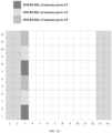
- FIG. 1A when only one (single) front-load symbol (an OFDM symbol with a corresponding number of 3 in the horizontal axis in the figure) is configured, sub-carriers (the longitudinal axis in the figure) of the OFDM symbol are divided into two groups, namely the OFDM symbol is divided into two CDM groups, each CDM group corresponds to a single OFDM symbol, and multiplexing of two ports is supported through an OCC manner.
- FIG. 1A when only one (single) front-load symbol (an OFDM symbol with a corresponding number of 3 in the horizontal axis in the figure) is configured, sub-carriers (the longitudinal axis in the figure) of the OFDM symbol are divided into two groups, namely the OFDM symbol is divided into two CDM groups, each CDM group corresponds to a single OFDM symbol, and multiplexing of two ports is supported through an OCC manner.
- one CDM group supports DMRS resources (REs) of antenna ports 0/1, and the other CDM group supports DMRS REs of antenna ports 2/3.
- FIG. 1B when two (double) front-load symbols (OFDM symbols with corresponding numbers of 3 and 4) are configured, sub-carriers of the OFDM symbols are divided into two groups, namely the OFDM symbols are divided into two CDM groups, each CDM group corresponds to double OFDM symbols, and multiplexing of four ports is supported through the OCC manner.
- one CDM group supports DMRS REs of antenna ports 0/1/4/5, and the other CDM group supports DMRS REs of antenna ports 2/3/6/7.
- front-load symbols are divided into three CDM groups.
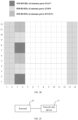
- FIG. 2A when only one (single) front-load symbol (an OFDM with a corresponding number of 3) is configured, sub-carriers of the OFDM symbol are divided into three groups, each group is composed of two adjacent subcarriers, namely the OFDM symbol is divided into three CDM groups, each CDM group corresponds to a single OFDM symbol, and multiplexing of two ports is supported through the OCC manner.
- FIG. 2A when only one (single) front-load symbol (an OFDM with a corresponding number of 3) is configured, sub-carriers of the OFDM symbol are divided into three groups, each group is composed of two adjacent subcarriers, namely the OFDM symbol is divided into three CDM groups, each CDM group corresponds to a single OFDM symbol, and multiplexing of two ports is supported through the OCC manner.
- one CDM group supports DMRS REs of the antenna ports 0/1
- one CDM group supports DMRS REs of the antenna ports 2/3
- another CDM group supports DMRS REs of antenna ports 4/5.
- FIG. 2B when two (double) front-load symbols (OFDM symbols with corresponding numbers of 3 and 4) are configured, sub-carriers of the OFDM symbols are divided into three groups, each group is composed of two adjacent subcarriers, namely the OFDM symbols are divided into three CDM groups, each CDM group corresponds to double OFDM symbols, and multiplexing of four ports is supported through the OCC manner.
- one CDM group supports DMRS REs of antenna ports 0/1/6/7
- one CDM group supports DMRS REs of antenna ports 2/3/8/9
- another CDM group supports DMRS REs of antenna ports 4/5/10/11.
- One Codeword Two Codewords: Codeword 0 enabled, Codeword 0 enabled, Codeword 1 disabled Codeword 1 enabled Value Number of CDM group(s) without data DMRS port(s) Number of front-load symbols Value Number of CDM group(s) without data DMRS port(s) Number of front-load symbols 0 1 0 1 0 2 0-4 2 1 1 1 1 1 2 0,1,2,3,4,6 2 2 1 0,1 1 2 2 0, 1, 2, 3, 4, 5, 6 2 3 2 0 1 3 2 0, 1, 2, 3, 4, 5, 6, 7 2 4 2 1 1 4-31 reserved reserved reserved 5 2 2 1
- One Codeword Codeword 0 enabled, Codeword 1 disabled Two Codewords: Codeword 0 enabled, Codeword 1 enabled Value Number of CDM group(s) without data DMRS port(s) Number of front-load symbols Value Number of CDM group(s) without data DMRS port(s) Number of front-load symbols 6 2 3 1 7 2 0, 1 8 2 2, 3 1 9 2 0-2 1 10 2 0-3 1 11 2 0,2 1
- a base station after allocating a DMRS port to the terminal, a base station sends corresponding TCI information to the terminal, and thus transmission configuration of the DMRS port may be indicated to the terminal.
- a value of the TCI information is "value" in Table 1 to Table 4.
- the base station sends downlink control information (DCI) to the terminal.
- DCI downlink control information
- the DCI includes TCI, and according to Table 1, the TCI information includes that the value is 11.
- the terminal may know the DMRS port 0 and the DMRS port 2 allocated by the base station to it according to the received TCI.
- QCL is a state hypothesis between the antenna ports, and if one antenna port and another antenna port are quasi co-located, it means that large-scale parameters of signals received by one antenna port may be integrally or partially inferred from large-scale parameters of signals received by another antenna port.
- the large-scale parameters include one or more of delay spread, Doppler spread, Doppler shift, space reception parameters, average channel gains, average time delay and the like.
- a plurality of TRPs or antenna panels involved in a CoMP process may correspond to a plurality of sectors where a plurality of TRPs or antenna panels different in geographic position have different directions.
- spatial differences of the TRPs or antenna panels will cause different large-scale channel parameters from receiving links of the different TRPs or antenna panels, such as Doppler frequency offset and delay spread.
- the large-scale parameters of channels directly affect adjustment and optimization of filter coefficients during channel estimation, and corresponding to signals sent by the different TRPs or antenna panels, different channel estimation filtering parameters should be configured to adapt to corresponding channel transmission properties.
- Two antenna ports are QCL under certain large-scale parameter significance, it means that these large-scale parameters of the two antenna ports are the same, alternatively, as long as certain large-scale parameters of the two ports are consistent, no matter whether they have differences in actual physical position or in direction of the corresponding antenna panels, the terminal may consider that the two antenna ports are from the same position (namely quasi co-located in site).
- QCL-Type A parameters involved in the QCL type include: ⁇ Doppler shift, Doppler spread, average time delay, delay spread ⁇ . All large-scale parameters, except a space reception parameter, are the same. For a frequency band below 6 GHz, the space reception parameter may be not needed.
- QCL-Type B parameters involved in the QCL type include: ⁇ Doppler shift, Doppler spread ⁇ . Only for following two cases of the frequency band below 6 GHz.
- a wide-beam reference signal may be used as QCL reference.
- a time frequency tracking reference signal TRS
- CSI-RS channel state information-reference signal
- Doppler parameters experienced by signals sent from the same site e.g., TRP or antenna panel
- scatterers covered by beams of different widths are different, so that the delay spread and average time delay parameters experienced by the signals during propagation will be obviously affected.
- the CSI-RS and the TRS are QCL under the significance of the delay spread and average time delay parameters.
- a target reference signal is insufficient in time domain density, but sufficient in frequency domain density.
- the time domain density of the CSI-RS depends on configuration and may be insufficient to accurately estimate Doppler parameters of a channel, and thus the Doppler parameters may be obtained from the TRS which is QCL with the CSI-RS.
- the frequency domain density of the CSI-RS is sufficient for estimating frequency domain parameters such as average time delay and delay spread, and thus these parameters may be obtained from the CSI-RS itself.
- QCL-Type C parameters involved in the QCL type include: ⁇ Doppler shift, average time delay ⁇ . It is only for the case that a synchronization signal block (SSB) is used as QCL reference in a frequency band above 6 GHz. Since the SSB is limited in occupied resource and density, it is generally assumed that only some relatively rough large-scale information can be obtained from the SSB, namely Doppler shift and average time delay, while other large-scale parameters need to be obtained from the target reference signal itself.
- SSB synchronization signal block
- QCL-Type D parameters involved in the QCL type include: ⁇ space reception parameter ⁇ . As described above, since this parameter is mainly for the frequency band above 6 GHz, it is used as a QCL type alone.
- one or more reference signals used as QCL reference contained in a TCI state may be one or more of a TRS, a CSI-RS and so on.
- a solution which can dynamically adjust a mapping relationship between TCI states and CDM groups is provided in the embodiment of the present application.
- FIG. 2C is a schematic diagram of a system for channel state information feedback provided by an embodiment of the present application
- the system includes a network side device 11 and a terminal 10.
- the network side device 11 configured to configure at least two DMRS ports for a terminal according to a required mapping relationship between transmission configuration indication state information (TCI states) and CDM groups, wherein the at least two DMRS ports belong to different DMRS CDM groups, and the quantities of the DMRS ports included in the different CDM groups are not exactly the same; and send DCI to the terminal, wherein the DCI includes DMRS port index values Values, the Values are Values pre-defined in a DMRS port allocation table, and the Values used to indicate a set of the at least two DMRS ports configured to the terminal, a number of CDM groups without data, and a number of front-load DMRS symbols, and are used to indicate the mapping relationship between the TCI states and the CDM groups.
- TCI states transmission configuration indication state information
- the terminal 10 configured to receive the DCI sent by the network side device, wherein the DCI includes the DMRS port index values Values; and determine the set of the at least two DMRS ports, the number of the CDM groups without data, the number of the front-load DMRS symbols, and the mapping relationship between the TCI states and the CDM groups configured by the network side device to the terminal according to the Values and the port allocation table.
- a mapping relationship between a TCI state and a corresponding CDM group may be obtained through a value
- a mapping relationship between corresponding TCI states and CDM groups may be obtained by selecting different values during port allocation according to actual requirements, and the manner may improve the flexibility of NC-JT.
- At least one first parameter combination is formed by a DMRS pilot type, a maximum number of front-load DMRS symbols being 1, the number of the CDM groups without data and the total number of the DMRS ports.
- a TCI field in the DCI corresponds to at least two TCI states
- at least two Values corresponding to that first parameter combination correspond to the same mapping relationship between the TCI states and the CDM groups.
- At least one second parameter combination is formed by a DMRS pilot type, a maximum number of front-load DMRS symbols being 2, the number of actually used DMRS symbols, the number of the CDM groups without data and the total number of the DMRS ports.
- a TCI field in the DCI corresponds to at least two TCI states
- at least two Values corresponding to that second parameter combination correspond to the same mapping relationship between the TCI states and the CDM groups.
- mapping relationships, corresponding to a plurality of Values, between the TCI states and the CDM groups are the same.
- the mapping relationships, corresponding to different Values, between the TCI states and the CDM groups under different parameter combinations are convenient to manage.
- the DMRS pilot type is 1
- the maximum number of front-load DMRS symbols is 1
- the number of the CDM groups without data is 2
- the total number of the DMRS ports is 3.
- Table 5 Value Correspondence between quantities of DMRS ports contained in CDM groups and CDM groups Number of DMRS ports contained in CDM groups CDM group 9 2 0 Correspondence 1 1 1 12 1 0 Correspondence 2 2 1
- port numbers corresponding to different Values may be partially multiplexed.
- the port numbers may also be not multiplexed, as long as the total quantities of the ports corresponding to the same CDM group are different when different Values are realized.
- a main difference from the manner 1 is that in the case of the same parameter combination, the different Values in the manner 1 correspond to the same mapping relationship between the TCI states and the CDM groups. Different Values in the manner 2 correspond to different mapping relationships between the TCI states and the CDM groups. It may be specifically implemented that for each first parameter combination, if the TCI field in the DCI corresponds to at least two TCI states, at least two Values corresponding to that first parameter combination correspond to different mapping relationships between the TCI states and the CDM groups.
- the DMRS pilot type is 1
- the maximum number of the front-load DMRS symbols is 1
- the number of the CDM groups without data is 2
- the total number of the DMRS ports is 3.
- the first mapping relationship is that the TCI state 0 corresponds to the CDM group 0 (containing two ports); and the TCI state 1 corresponds to the CDM group 1 (including one port).
- the second mapping relationship is that the TCI state 0 corresponds to the CDM group 1 (containing two port); and the TCI state 1 corresponds to the CDM group 0 (including one port).
- the TCI field in the DCI corresponds to at least two TCI states
- at least two Values corresponding to that second parameter combination correspond to different mapping relationships between the TCI states and the CDM groups.
- the port numbers corresponding to the Values corresponding to each first parameter combination are the same; and/or, the port numbers corresponding to the Values corresponding to each second parameter combination are the same. Accordingly, when the port allocation table is configured, the same parameter combination only needs to use the same port number, so that configuration of the port allocation table is simple and easy.
- the port numbers contained in the CDM group 0 are (0, 1), and the port numbers contained in the CDM group 1 are (2).
- the mapping relationship between the TCI states and the CDM groups is dynamically adjusted by switching different Values in the case of the same parameter combination.
- corresponding Values are added in above Table 1 to Table 4.
- TCI state 0 corresponds to the CDM group
- TCI state 1 corresponds to the CDM group
- the pre-defined correspondence between the TCI states and the CDM groups may be the basis.
- the TCI state 0 corresponds to the CDM group
- the TCI state 1 corresponds to the CDM group.
- port allocation corresponding to the newly added Value one port belongs to the CDM group 0, while remaining two ports belong to the CDM group 1, as shown in Table 6-1.
- port allocation corresponding to the added Value is ports 0/2/3, wherein the port 0 belongs to the CDM group 0, while the ports 2/3 belong to the CDM group 1.
- the correspondence between the TCI states and the CDM groups is pre-defined, for example, when the TCI field indicated in the DCI corresponds to two TCI states, the TCI state 0 corresponds to the CDM group 0, while the TCI state 1 corresponds to the CDM group 1.
- the TCI state 1 corresponds to the CDM group 1 (containing the port 2).
- the TCI state 1 corresponds to the CDM group 1 (containing the ports 2, 3).
- a mapping relationship between the CDM groups and the TCI states is pre-defined, for example, when the TCI field indicated in the DCI corresponds to two TCI states, the TCI state 0 corresponds to the CDM group 0, while the TCI state 1 corresponds to the CDM group 1.
- Port allocation corresponding to the newly added Value is also the ports 0/1/2, and meanwhile, for the newly added Value, the mapping relationship between the CDM groups and the TCI states is also pre-defined, as shown in Table 6-2, for example, when the TCI field indicated in the DCI corresponds to two TCI states, the TCI state 1 corresponds to the CDM group 0, while the TCI state 0 corresponds to the CDM group 1.
- the TCI state 1 corresponds to the CDM group 1 (containing the port 2).
- the TCI state 1 corresponds to the CDM group 0 (containing the ports 0, 1).
- the TCI state 0 corresponds to the CDM group
- the TCI state 1 corresponds to the CDM group.
- the pre-defined correspondence between the TCI states and the CDM groups may be the basis.
- the TCI state 0 corresponds to the CDM group
- the TCI state 1 corresponds to the CDM group.
- the DMRS table does not need to be changed (new Values do not need to be added for this case), but the correspondence between the TCI states and the CDM groups needs to be determined. For example, it may be agreed that the TCI state 0 corresponds to the CDM group 0, and the TCI state 1 corresponds to the CDM group 1.
- the network side device and the terminal may agree that the TCI state 0 corresponds to the CDM group 0, while the TCI state 1 corresponds to the CDM group 1 (or the TCI state 0 corresponds to the CDM group 1, while the TCI state 1 corresponds to the CDM group 0).
- port allocation corresponding to the newly added Value one port belongs to the CDM group 0, while remaining two ports belong to the CDM group 1, as shown in Table 7-1.
- port allocation corresponding to the added Value is the ports 0/2/3, wherein the port 0 belongs to the CDM group 0, while the ports 2/3 belong to the CDM group 1.
- the correspondence between the TCI states and the CDM groups is pre-defined, for example, when the TCI field indicated in the DCI corresponds to two TCI states, the TCI state 0 corresponds to the CDM group 0, while the TCI state 1 corresponds to the CDM group 1.
- the TCI state 1 corresponds to the CDM group 1 (containing the port 2).
- the TCI state 1 corresponds to the CDM group 1 (containing the ports 2, 3).
- a mapping relationship between the CDM groups and the TCI states is pre-defined, for example, when the TCI field indicated in the DCI corresponds to two TCI states, the TCI state 0 corresponds to the CDM group 0, while the TCI state 1 corresponds to the CDM group 1.
- the TCI state 1 corresponds to the CDM group 1 (containing the port 2).
- the TCI state 1 corresponds to the CDM group 0 (containing the ports 0, 1).
- the pre-defined correspondence between the TCI states and the CDM groups may be the basis.
- the TCI state 0 corresponds to the CDM group
- the TCI state 1 corresponds to the CDM group.
- the pre-defined correspondence between the TCI states and the CDM groups may be the basis. For example, the TCI state 0 or 1 is used.
- the DMRS table does not need to be changed (new Values do not need to be added for this case), but the correspondence between the TCI states and the CDM groups needs to be determined. For example, it may be agreed that the TCI state 0 corresponds to the CDM group 0, and the TCI state 1 corresponds to the CDM group 1.
- port allocation corresponding to the newly added Value two ports belong to the CDM group 0, while three ports belong to the CDM group 1, as shown in Table 7-1.
- port allocation corresponding to the added Value is ports 0, 1, 2, 3, 6, wherein the ports 0/1 belong to the CDM group 0, while the ports 2/3/6 belong to the CDM group 1.
- TCI states and the CDM groups are pre-defined, and when the TCI field indicated in the DCI corresponds to two TCI states, the TCI state 0 corresponds to the CDM group 0, while the TCI state 1 corresponds to the CDM group 1.
- the mapping relationship between the CDM groups and the TCI states is pre-defined, for example, when the TCI field indicated in the DCI corresponds to two TCI states, the TCI state 0 corresponds to the CDM group 0, while the TCI state 1 corresponds to the CDM group 1.
- Port allocation corresponding to the newly added Value is also 0-4, and meanwhile, for the newly added Value, the mapping relationship between the CDM groups and the TCI states is also pre-defined, as shown in Table 7-2, for example, when the TCI field indicated in the DCI corresponds to two TCI states, the TCI state 1 corresponds to the CDM group 0, while the TCI state 0 corresponds to the CDM group 1.
- port allocation corresponding to the added Value is ports 0, 1, 2, 3, 4, 6, 7, wherein the ports 0/1/4 belong to the CDM group 0, while the ports 2/3/6/7 belong to the CDM group 1.
- the TCI state 0 corresponds to the CDM group 0
- the TCI state 1 corresponds to the CDM group 1.
- Number of front-load symbols Number of CDM group(s) without data DMRS port(s)
- Codeword 0 enabled, Codeword 1 disabled Two Codewords: Codeword 0 enabled, Codeword 1 enabled Value Number of CDM group(s) without data DMRS port(s) Number of front-load symbols Value Number of CDM group(s) without data DMRS port(s) Number of front-load symbols 0 1 0 1 0 2 0-4 2 1 1 1 1 1 2 0, 1,2,3,4,6 2 2 1 0, 1 1 2 2 0, 1, 2, 3, 4, 5, 6 2 3 2 0 1 3 2 0, 1, 2, 3, 4, 5, 6, 7 2 4 2 1 1 4 2 0-4 2 5 2 2 1 5 2 0, 1, 2, 3, 4, 5, 6 2 6 2 3 1 6-31 reserved reserved reserved reserved reserved 7 2 0, 1 1 8 2 2, 3 1 9 2 0-2 1 10 2 0-3 1 11 2 0,2 1 12 2 0 2 13 2 1 2 14 2 2 2 2 15 2 3 2 16 2 4 2 17 2 5 2 18 2 6 2 19 2 7 2 20 2 0, 1 2 21 2 2, 3 2 22 2 4, 5 2 23 2 6, 7 2 24 2 0, 4 2 25 2 2,
- the pre-defined correspondence between the TCI states and the CDM groups may be the basis.
- the TCI state 0 corresponds to the CDM group
- the TCI state 1 corresponds to the CDM group.
- the pre-defined correspondence between the TCI states and the CDM groups may be the basis.
- the TCI state 0 corresponds to the CDM group
- the TCI state 1 corresponds to the CDM group.
- the DMRS table does not need to be changed (new Values do not need to be added for this case), but the correspondence between the TCI states and the CDM groups needs to be determined. For example, it may be agreed that the TCI state 0 corresponds to the CDM group 0, and the TCI state 1 corresponds to the CDM group 1.
- the TCI state 0 corresponds to the CDM group 0
- the TCI state 1 corresponds to the CDM group 1.
- the TCI state 1 corresponds to the CDM group 1 (containing the port 2).
- the TCI state 1 corresponds to the CDM group 1 (containing the ports 2, 3).
- Port allocation corresponding to the newly added Value is also the ports 0/1/2, and meanwhile, for the newly added Value, the mapping relationship between the CDM groups and the TCI states is also pre-defined, for example, when the TCI field indicated in the DCI corresponds to two TCI states, the TCI state 1 corresponds to the CDM group 0, while the TCI state 0 corresponds to the CDM group 1.
- the TCI state 0 corresponds to the CDM group 0 (containing the ports 0,1), while the TCI state 1 corresponds to the CDM group 1 (containing the port 2).
- the TCI state 1 corresponds to the CDM group 1 (containing the port 2).
- the TCI state 1 corresponds to the CDM group 1 (containing the ports 4, 5).
- Codeword 0 enabled Codeword 1 disabled
- Two codewords Codeword 0 enabled, Codeword 1 enabled Value Number of CDM group(s) without data DMRS port(s) Value Number of CDM group(s) without data DMRS port(s) 0 1 0 0 3 0-4 1 1 1 1 3 0-5 2 1 0, 1 2 3 0-4 3 2 0 3 3 0-4 4 2 1 4 3 0-4 5 2 2 5 3 0-5 6 2 3 6-31 reserved reserved 7 2 0, 1 8 2 2, 3 9 2 0-2 10 2 0-3 11 3 0 12 3 1 13 3 2 14 3 3 15 3 4 16 3 5 17 3 0, 1 18 3 2, 3 19 3 4, 5 20 3 0-2 21 3 3-5 22 3 0-3 23 2 0,2 24 2 0-2 25-31 Reserved Reserved
- TCI state 0 corresponds to the CDM group
- TCI state 1 corresponds to the CDM group
- the allocated DMRS ports only belong to one CDM group (only one TCI state is needed at the moment) and the TCI field indicated by the DCI corresponds to two TCI states
- the pre-defined correspondence between the TCI states and the CDM groups may be the basis.
- the TCI state 0 corresponds to the CDM group
- the TCI state 1 corresponds to the CDM group.
- the DMRS table does not need to be changed (new Values do not need to be added for this case), but the correspondence between the TCI states and the CDM groups needs to be determined. For example, it may be agreed that the TCI state 0 corresponds to the CDM group 0, and the TCI state 1 corresponds to the CDM group 1.
- the TCI state 0 corresponds to the CDM group 0
- the TCI state 1 corresponds to the CDM group 1.
- the TCI state 1 corresponds to the CDM group 1 (containing the port 2).
- the TCI state 1 corresponds to the CDM group 1 (containing the ports 2, 3).
- Port allocation corresponding to the newly added Value is also the ports 0/1/2, and meanwhile, for the newly added Value, the mapping relationship between the CDM groups and the TCI states is also pre-defined, for example, when the TCI field indicated in the DCI corresponds to two TCI states, the TCI state 1 corresponds to the CDM group 0, while the TCI state 0 corresponds to the CDM group 1.
- the TCI state 1 corresponds to the CDM group 1 (containing the port 2).
- the TCI state 1 corresponds to the CDM group 0 (containing the ports 0, 1).
- the TCI state 1 corresponds to the CDM group 1 (containing the port 2).
- the TCI state 1 corresponds to the CDM group 1 (containing the ports 4, 5).
- the pre-defined correspondence between the TCI states and the CDM groups may be the basis.
- the TCI state 0 corresponds to the CDM group
- the TCI state 1 corresponds to the CDM group.
- the pre-defined correspondence between the TCI states and the CDM groups may be the basis.
- the TCI state 0 corresponds to the CDM group
- the TCI state 1 corresponds to the CDM group.
- the TCI state 0 corresponds to the CDM group 0
- the TCI state 1 corresponds to the CDM group 1
- the TCI state 1 corresponds to the CDM group 0
- the allocated DMRS ports belong to two CDM groups (both the manner 1 and the manner 2 may be used, and description is made here only by taking the manner 1 as an example).
- the TCI state 0 corresponds to the CDM group 0
- the TCI state 1 corresponds to the CDM group 1
- the TCI state 1 corresponds to the CDM group 0
- the terminal receives the DCI sent by the network side device, and then determines the set of DMRS ports allocated by the network side device to the terminal, the number of the CDM groups without data and the mapping relationship between the TCI states and the CDM groups according to the Values and the port allocation table.
- the terminal may determine the mapping relationship, corresponding to the Value, between the TCI states and the CDM groups according to a pre-definition.
- the mapping relationship, corresponding to the Value, between the TCI states and the CDM groups is the same at the terminal side and a network side, which is not repeated here.
- FIG. 3 is a network side device provided by an embodiment of the present application.
- the network side device includes: at least one processor 800, at least one memory 801, a transceiver 802 and a bus interface.
- the processor 800 is responsible for managing the bus architecture and general processing, and the memory 801 may store data used when the processor 800 executes operations.
- the transceiver 802 is configured to receive and send data under the control of the processor 800.
- the memory 801 stores program codes, and when the program codes are executed by the processor 800, the processor 800 is made to execute the following process: at least two DMRS ports are configured for a terminal according to a required mapping relationship between TCI states and CDM groups, wherein the at least two DMRS ports belong to different DMRS CDM groups, and the quantities of the DMRS ports included in the different CDM groups are not exactly the same; and DCI is sent to the terminal, wherein the DCI includes DMRS port index values Values, the Values are Values pre-defined in a DMRS port allocation table, and the Values are used to indicate a set of the at least two DMRS ports allocated to the terminal and the number of CDM groups without data, and are used to indicate the mapping relationship between the TCI states and the CDM groups.
- At least one first parameter combination is formed by a DMRS pilot type, a maximum number of front-load DMRS symbols being 1, the number of CDM groups without data and the total number of DMRS ports.
- a TCI field in the DCI corresponds to at least two TCI states
- at least two Values corresponding to that first parameter combination correspond to the same mapping relationship between the TCI states and the CDM groups.
- At least one second parameter combination is formed by a DMRS pilot type, a maximum number of front-load DMRS symbols being 2, the number of actually used DMRS symbols, the number of CDM groups without data and the total number of DMRS ports.
- a TCI field in the DCI corresponds to at least two TCI states
- at least two Values corresponding to that second parameter combination correspond to the same mapping relationship between the TCI states and the CDM groups.
- At least one first parameter combination is formed by a DMRS pilot type, a maximum number of front-load DMRS symbols being 1, the number of the CDM groups without data and the total number of DMRS ports.
- a TCI field in the DCI corresponds to at least two TCI states
- the mapping relationships, corresponding to the at least two Values corresponding to that first parameter combination, between the TCI states and the CDM groups are different.
- At least one second parameter combination is formed by a DMRS pilot type, a maximum number of front-load DMRS symbols being 2, the number of actually used DMRS symbols, the number of the CDM groups without data and the total number of DMRS ports.
- a TCI field in the DCI corresponds to at least two TCI states
- the mapping relationships, corresponding to the at least two Values corresponding to that first parameter combination, between the TCI states and the CDM groups are different.
- port numbers corresponding to the Values corresponding to each first parameter combination are the same; and/or, port numbers corresponding to the Values corresponding to each second parameter combination are the same.
- FIG. 4 is a network side device provided by an embodiment of the present application.
- the network side device includes: at least one processor 900, at least one memory 901, a transceiver 902 and a bus interface.
- the processor 900 is responsible for managing the bus architecture and general processing, and the memory 901 may store data used when the processor 900 executes operations.
- the transceiver 902 is configured to receive and send data under the control of the processor 900.
- the memory 901 stores program codes, and when the program codes are executed by the processor 900, the processor 900 is made to execute the following process: DCI sent by the network side device is received, wherein the DCI includes DMRS port index values Values, and the Values are Values pre-defined in a DMRS port allocation table; and a set of DMRS ports allocated by the network side device to a terminal, the number of CDM groups without data and a mapping relationship between TCI states and CDM groups are determined according to the Values and the port allocation table, wherein at least two DMRS ports included in the port set belong to different DMRS CDM groups, the quantities of the DMRS ports included in the different CDM groups are not exactly the same, and the at least two ports are determined by the network side device according to a required mapping relationship between the TCI states and the CDM groups.
- the processor is further configured to execute: determining the mapping relationship, corresponding to the Values, between the TCI states and the CDM groups according to a pre-definition.
- At least one first parameter combination is formed by a DMRS pilot type, a maximum number of front-load DMRS symbols being 1, the number of CDM groups without data and the total number of DMRS ports.
- a TCI field in the DCI corresponds to at least two TCI states
- at least two Values corresponding to that first parameter combination correspond to the same mapping relationship between the TCI states and the CDM groups.
- At least one second parameter combination is formed by a DMRS pilot type, a maximum number of front-load DMRS symbols being 2, the number of actually used DMRS symbols, the number of CDM groups without data and the total number of DMRS ports.
- a TCI field in the DCI corresponds to at least two TCI states
- at least two Values corresponding to that second parameter combination correspond to the same mapping relationship between the TCI states and the CDM groups.
- At least one first parameter combination is formed by a DMRS pilot type, a maximum number of front-load DMRS symbols being 1, the number of the CDM groups without data and the total number of DMRS ports.
- a TCI field in the DCI corresponds to at least two TCI states
- the mapping relationships, corresponding to the at least two Values corresponding to that first parameter combination, between the TCI states and the CDM groups are different.
- At least one second parameter combination is formed by a DMRS pilot type, a maximum number of front-load DMRS symbols being 2, the number of actually used DMRS symbols, the number of the CDM groups without data and the total number of DMRS ports.
- a TCI field in the DCI corresponds to at least two TCI states
- the mapping relationships, corresponding to the at least two Values corresponding to that first parameter combination, between the TCI states and the CDM groups are different.
- port numbers corresponding to the Values corresponding to each first parameter combination are the same; and/or, port numbers corresponding to the Values corresponding to each second parameter combination are the same.
- FIG. 5 is a schematic flow diagram of a transmission configuration indication method of a DMRS port provided by an embodiment of the present application. The method includes the following.
- Step 501 a network side device configures at least two DMRS ports for a terminal according to a required mapping relationship between TCI states and CDM groups, wherein the at least two DMRS ports belong to different DMRS CDM groups, and the quantities of the DMRS ports included in the different CDM groups are not exactly the same.
- Step 502 DCI is sent to the terminal, wherein the DCI includes DMRS port index values (Values), the Values are Values pre-defined in a DMRS port allocation table, and the Values are used to indicate a set of DMRS ports allocated to the terminal and the number of CDM groups without data, and used to indicate the mapping relationship between the TCI states and the CDM groups.
- DMRS port index values Values
- the Values are Values pre-defined in a DMRS port allocation table
- the Values are used to indicate a set of DMRS ports allocated to the terminal and the number of CDM groups without data, and used to indicate the mapping relationship between the TCI states and the CDM groups.
- At least one first parameter combination is formed by a DMRS pilot type, a maximum number of front-load DMRS symbols being 1, the number of the CDM groups without data and the total number of the DMRS ports.
- a TCI field in the DCI corresponds to at least two TCI states
- at least two Values corresponding to that first parameter combination correspond to the same mapping relationship between the TCI states and the CDM groups.
- At least one second parameter combination is formed by a DMRS pilot type, a maximum number of front-load DMRS symbols being 2, the number of actually used DMRS symbols, the number of the CDM groups without data and the total number of the DMRS ports.
- a TCI field in the DCI corresponds to at least two TCI states
- at least two Values corresponding to that second parameter combination correspond to the same mapping relationship between the TCI states and the CDM groups.
- At least one first parameter combination is formed by the DMRS pilot type, the maximum number of the front-load DMRS symbols being 1, the number of the CDM groups without data and the total number of the DMRS ports.
- the mapping relationships, corresponding to the at least two Values corresponding to that first parameter combination, between the TCI states and the CDM groups are different.
- At least one second parameter combination is formed by the DMRS pilot type, the maximum number of the front-load DMRS symbols being 2, the number of the actually used DMRS symbols, the number of the CDM groups without data and the total number of the DMRS ports.
- the mapping relationships, corresponding to the at least two Values corresponding to that second parameter combination, between the TCI states and the CDM groups are different.
- port numbers corresponding to the Values corresponding to each first parameter combination are the same; and/or, port numbers corresponding to the Values corresponding to each second parameter combination are the same.
- FIG. 6 is a schematic flow diagram of a transmission configuration indication method of a DMRS port suitable for a terminal provided by an embodiment of the present application. As shown in FIG. 6 , the method includes the following.
- Step 601 the terminal receives DCI sent by a network side device, wherein the DCI includes DMRS port index values (Values), and the Values are Values pre-defined in a DMRS port allocation table.
- the DCI includes DMRS port index values (Values), and the Values are Values pre-defined in a DMRS port allocation table.
- Step 602 a set of DMRS ports allocated by the network side device to the terminal, the number of CDM groups without data and a mapping relationship between TCI states and CDM groups are determined according to the Values and the port allocation table, wherein at least two DMRS ports included in the port set belong to different DMRS CDM groups, the quantities of the DMRS ports included in the different CDM groups are not exactly the same, and the at least two ports are determined by the network side device according to a required mapping relationship between the TCI states and the CDM groups.
- determining the mapping relationship between the TCI states and the CDM groups according to the Values includes: the mapping relationship, corresponding to the Values, between the TCI states and the CDM groups is determined according to a pre-definition.
- At least one first parameter combination is formed by a DMRS pilot type, a maximum number of front-load DMRS symbols being 1, the number of the CDM groups without data and the total number of the DMRS ports.
- a TCI field in the DCI corresponds to at least two TCI states
- at least two Values corresponding to that first parameter combination correspond to the same mapping relationship between the TCI states and the CDM groups.
- At least one second parameter combination is formed by a DMRS pilot type, a maximum number of front-load DMRS symbols being 2, the number of actually used DMRS symbols, the number of the CDM groups without data and the total number of the DMRS ports.
- a TCI field in the DCI corresponds to at least two TCI states
- at least two Values corresponding to that second parameter combination correspond to the same mapping relationship between the TCI states and the CDM groups.
- At least one first parameter combination is formed by the DMRS pilot type, the maximum number of the front-load DMRS symbols being 1, the number of the CDM groups without data and the total number of the DMRS ports.
- the mapping relationships, corresponding to the at least two Values corresponding to that first parameter combination, between the TCI states and the CDM groups are different.
- At least one second parameter combination is formed by the DMRS pilot type, the maximum number of the front-load DMRS symbols being 2, the number of the actually used DMRS symbols, the number of the CDM groups without data and the total number of the DMRS ports.
- the mapping relationships, corresponding to the at least two Values corresponding to that second parameter combination, between the TCI states and the CDM groups are different.
- port numbers corresponding to the Values corresponding to each first parameter combination are the same; and/or, port numbers corresponding to the Values corresponding to each second parameter combination are the same.
- FIG. 7 is a schematic structural diagram of a network side device provided by the present application.
- the network side device includes: a determining module 71, configured to configure at least two DMRS ports for a terminal according to a required mapping relationship between TCI states and CDM groups, wherein the at least two DMRS ports belong to different DMRS CDM groups, and the quantities of the DMRS ports included in the different CDM groups are not exactly the same; and an executing module 72, configured to send DCI to the terminal, wherein the DCI includes DMRS port index values (Value)s, the Values are Values pre-defined in a DMRS port allocation table, and the Values are used to indicate a set of DMRS ports allocated to the terminal and the number of CDM groups without data, and used to indicate the mapping relationship between the TCI states and the CDM groups.
- a determining module 71 configured to configure at least two DMRS ports for a terminal according to a required mapping relationship between TCI states and CDM groups, wherein the at
- At least one first parameter combination is formed by a DMRS pilot type, a maximum number of front-load DMRS symbols being 1, the number of the CDM groups without data and the total number of the DMRS ports.
- a TCI field in the DCI corresponds to at least two TCI states
- at least two Values corresponding to that first parameter combination correspond to the same mapping relationship between the TCI states and the CDM groups.
- At least one second parameter combination is formed by a DMRS pilot type, a maximum number of front-load DMRS symbols being 2, the number of actually used DMRS symbols, the number of the CDM groups without data and the total number of DMRS ports.
- a TCI field in the DCI corresponds to at least two TCI states
- at least two Values corresponding to that second parameter combination correspond to the same mapping relationship between the TCI states and the CDM groups.
- At least one first parameter combination is formed by a DMRS pilot type, a maximum number of front-load DMRS symbols being 1, the number of the CDM groups without data and the total number of DMRS ports.
- a TCI field in the DCI corresponds to at least two TCI states
- the mapping relationships, corresponding to the at least two Values corresponding to that first parameter combination, between the TCI states and the CDM groups are different.
- At least one second parameter combination is formed by a DMRS pilot type, a maximum number of front-load DMRS symbols being 2, the number of actually used DMRS symbols, the number of the CDM groups without data and the total number of DMRS ports.
- a TCI field in the DCI corresponds to at least two TCI states
- the mapping relationships, corresponding to the at least two Values corresponding to that first parameter combination, between the TCI states and the CDM groups are different.
- port numbers corresponding to the Values corresponding to each first parameter combination are the same; and/or, port numbers corresponding to the Values corresponding to each second parameter combination are the same.
- FIG. 8 is a schematic structural diagram of a terminal provided by an embodiment of the present application.
- the terminal includes: a receiving module 81, configured to receive DCI sent by a network side device, wherein the DCI includes DMRS port index values (Values), and the Values are Values pre-defined in a DMRS port allocation table; and a parameter determining module 82, configured to determine a set of DMRS ports allocated by the network side device to the terminal, the number of CDM groups without data and a mapping relationship between TCI states and CDM groups according to the Values and the port allocation table, wherein at least two DMRS ports included in the port set belong to different DMRS CDM groups, the quantities of the DMRS ports included in the different CDM groups are not exactly the same, and the at least two DMRS ports are determined by the network side device according to a required mapping relationship between the TCI states and the CDM groups.
- a receiving module 81 configured to receive DCI sent by a network side device, wherein the DCI
- the parameter determining module 82 is configured to determine the mapping relationship, corresponding to the Values, between the TCI states and the CDM groups according to a pre-definition.
- At least one first parameter combination is formed by a DMRS pilot type, a maximum number of front-load DMRS symbols being 1, the number of the CDM groups without data and the total number of DMRS ports.
- a TCI field in the DCI corresponds to at least two TCI states
- at least two Values corresponding to that first parameter combination correspond to the same mapping relationship between the TCI states and the CDM groups.
- At least one second parameter combination is formed by a DMRS pilot type, a maximum number of front-load DMRS symbols being 2, the number of actually used DMRS symbols, the number of the CDM groups without data and the total number of DMRS ports.
- a TCI field in the DCI corresponds to at least two TCI states
- at least two Values corresponding to that second parameter combination correspond to the same mapping relationship between the TCI states and the CDM groups.
- At least one first parameter combination is formed by a DMRS pilot type, a maximum number of front-load DMRS symbols being 1, the number of the CDM groups without data and the total number of DMRS ports.
- a TCI field in the DCI corresponds to at least two TCI states
- the mapping relationships, corresponding to the at least two Values corresponding to that first parameter combination, between the TCI states and the CDM groups are different.
- At least one second parameter combination is formed by a DMRS pilot type, a maximum number of front-load DMRS symbols being 2, the number of actually used DMRS symbols, the number of the CDM groups without data and the total number of DMRS ports.
- a TCI field in the DCI corresponds to at least two TCI states
- the mapping relationships, corresponding to the at least two Values corresponding to that first parameter combination, between the TCI states and the CDM groups are different.
- port numbers corresponding to the Values corresponding to each first parameter combination are the same; and/or, port numbers corresponding to the Values corresponding to each second parameter combination are the same.
- An embodiment of the present application further provides a computer-readable non-volatile storage medium, including program codes.
- the program codes run on a computing terminal, the program codes are configured to enable the computing terminal to execute the steps of the transmission configuration indication method of the DMRS port of the embodiments of the present application.
- the present application may be further implemented through hardware and/or software (including firmware, resident software, microcodes, etc.). Further, the present application may take the form of a computer program product on a computer usable or computer readable storage medium having computer usable or computer readable program codes implemented in the medium for use by or in combination with an instruction execution system.
- a computer usable or computer-readable medium may be any medium that may contain, store, communicate, transmit, or convey a program for use by, or in combination with, an instruction execution system, apparatus, or device.
Landscapes
- Engineering & Computer Science (AREA)
- Signal Processing (AREA)
- Computer Networks & Wireless Communication (AREA)
- Mobile Radio Communication Systems (AREA)
- Small-Scale Networks (AREA)
Applications Claiming Priority (3)
| Application Number | Priority Date | Filing Date | Title |
|---|---|---|---|
| CN201910272864.1A CN111786757B (zh) | 2019-04-04 | 2019-04-04 | Dmrs端口的传输配置指示方法、相关装置及存储介质 |
| EP20781850.1A EP3952185B1 (fr) | 2019-04-04 | 2020-02-07 | Procédé d'indication de configuration de transmission d'un port dmrs et appareil associé, et support d'informations |
| PCT/CN2020/074552 WO2020199752A1 (fr) | 2019-04-04 | 2020-02-07 | Procédé d'indication de configuration de transmission d'un port dmrs et appareil associé, et support d'informations |
Related Parent Applications (2)
| Application Number | Title | Priority Date | Filing Date |
|---|---|---|---|
| EP20781850.1A Division EP3952185B1 (fr) | 2019-04-04 | 2020-02-07 | Procédé d'indication de configuration de transmission d'un port dmrs et appareil associé, et support d'informations |
| EP20781850.1A Division-Into EP3952185B1 (fr) | 2019-04-04 | 2020-02-07 | Procédé d'indication de configuration de transmission d'un port dmrs et appareil associé, et support d'informations |
Publications (3)
| Publication Number | Publication Date |
|---|---|
| EP4236091A2 true EP4236091A2 (fr) | 2023-08-30 |
| EP4236091A3 EP4236091A3 (fr) | 2023-11-01 |
| EP4236091B1 EP4236091B1 (fr) | 2024-10-09 |
Family
ID=72664631
Family Applications (2)
| Application Number | Title | Priority Date | Filing Date |
|---|---|---|---|
| EP23180513.6A Active EP4236091B1 (fr) | 2019-04-04 | 2020-02-07 | Procédé d'indication de configuration de transmission d'un port dmrs et appareil associé, et support d'informations |
| EP20781850.1A Active EP3952185B1 (fr) | 2019-04-04 | 2020-02-07 | Procédé d'indication de configuration de transmission d'un port dmrs et appareil associé, et support d'informations |
Family Applications After (1)
| Application Number | Title | Priority Date | Filing Date |
|---|---|---|---|
| EP20781850.1A Active EP3952185B1 (fr) | 2019-04-04 | 2020-02-07 | Procédé d'indication de configuration de transmission d'un port dmrs et appareil associé, et support d'informations |
Country Status (6)
| Country | Link |
|---|---|
| US (1) | US12004148B2 (fr) |
| EP (2) | EP4236091B1 (fr) |
| KR (1) | KR102816502B1 (fr) |
| CN (1) | CN111786757B (fr) |
| TW (1) | TWI739314B (fr) |
| WO (1) | WO2020199752A1 (fr) |
Families Citing this family (13)
| Publication number | Priority date | Publication date | Assignee | Title |
|---|---|---|---|---|
| US11626914B2 (en) * | 2020-05-27 | 2023-04-11 | Qualcomm Incorporated | Demodulation reference signal configuration selection and reporting |
| US12609795B2 (en) * | 2020-10-15 | 2026-04-21 | Panasonic Intellectual Property Corporation Of America | Terminal, base station, and communication method |
| CN115189835B (zh) * | 2021-04-02 | 2024-08-23 | 大唐移动通信设备有限公司 | 信息配置方法、装置、网络设备及终端设备 |
| CN115913483B (zh) * | 2021-08-19 | 2024-07-19 | 展讯通信(上海)有限公司 | Dmrs发送、接收方法及装置、计算机可读存储介质 |
| CN115913497A (zh) * | 2021-09-30 | 2023-04-04 | 中兴通讯股份有限公司 | 传输解调参考信号的方法、节点和存储介质 |
| CN115883043B (zh) * | 2021-09-30 | 2025-10-31 | 维沃移动通信有限公司 | 通信指示的方法、终端及网络侧设备 |
| WO2023133790A1 (fr) * | 2022-01-14 | 2023-07-20 | Lenovo (Beijing) Limited | Procédés et appareil de signalisation pour indiquer des ports dmrs |
| MX2024005509A (es) * | 2022-01-28 | 2024-05-23 | Zte Corp | Sistemas y metodos para configuracion e indicacion de puertos dmrs. |
| CN117322095A (zh) * | 2022-04-29 | 2023-12-29 | 北京小米移动软件有限公司 | 多天线面板协作传输的解调参考信号端口分配方法及装置 |
| CN117014888A (zh) * | 2022-04-29 | 2023-11-07 | 华为技术有限公司 | 发送解调参考信号的方法及装置 |
| WO2023206568A1 (fr) * | 2022-04-29 | 2023-11-02 | 北京小米移动软件有限公司 | Procédé et appareil d'attribution de port de signal de référence de démodulation pour une transmission coordonnée de panneau à antennes multiples |
| CN117675136A (zh) * | 2022-08-12 | 2024-03-08 | 华为技术有限公司 | Dmrs端口指示方法、装置及存储介质 |
| CN117811710A (zh) * | 2022-09-30 | 2024-04-02 | 华为技术有限公司 | 一种参考信号端口指示方法及装置 |
Family Cites Families (12)
| Publication number | Priority date | Publication date | Assignee | Title |
|---|---|---|---|---|
| JP5813444B2 (ja) * | 2011-09-30 | 2015-11-17 | シャープ株式会社 | 基地局、端末、通信システムおよび通信方法 |
| CN106470087B (zh) | 2015-08-19 | 2020-06-26 | 中国移动通信集团公司 | Dmrs指示方法、系统、基站及用户设备 |
| CN118473492A (zh) * | 2017-01-06 | 2024-08-09 | 索尼公司 | 波束失效恢复 |
| CN109391441B (zh) * | 2017-08-11 | 2020-10-30 | 电信科学技术研究院 | 一种控制信息的发送方法、接收方法、基站及终端 |
| CN108809609B (zh) * | 2017-08-11 | 2019-07-09 | 华为技术有限公司 | 一种dmrs指示和接收方法,发射端和接收端 |
| WO2019050367A1 (fr) * | 2017-09-08 | 2019-03-14 | 엘지전자 주식회사 | Procédé et dispositif de transmission ou de réception d'un signal de référence dans un système de communication sans fil |
| US10779171B2 (en) | 2017-09-11 | 2020-09-15 | Mediatek Inc. | Downlink spatial transmission and spatial reception mechanism in multi-beam operation |
| CN108111283B (zh) * | 2017-11-03 | 2021-12-14 | 中兴通讯股份有限公司 | 一种参考信号的传输方法及设备 |
| US11265122B2 (en) * | 2018-10-03 | 2022-03-01 | Qualcomm Incorporated | Multi-transmit receive point demodulation reference signal port identification |
| US11159270B2 (en) * | 2018-11-08 | 2021-10-26 | Qualcomm Incorporated | Separately communicating demodulation reference signal-based channel information for multiple transmit receive points |
| KR102251727B1 (ko) * | 2019-08-14 | 2021-05-14 | 엘지전자 주식회사 | 무선 통신 시스템에서 하향링크 데이터를 송수신 하는 방법 및 이에 대한 장치 |
| WO2021030954A1 (fr) * | 2019-08-16 | 2021-02-25 | 华为技术有限公司 | Procédé et appareil de détermination de mode de transmission |
-
2019
- 2019-04-04 CN CN201910272864.1A patent/CN111786757B/zh active Active
-
2020
- 2020-02-07 KR KR1020217036183A patent/KR102816502B1/ko active Active
- 2020-02-07 WO PCT/CN2020/074552 patent/WO2020199752A1/fr not_active Ceased
- 2020-02-07 EP EP23180513.6A patent/EP4236091B1/fr active Active
- 2020-02-07 EP EP20781850.1A patent/EP3952185B1/fr active Active
- 2020-02-07 US US17/600,608 patent/US12004148B2/en active Active
- 2020-02-24 TW TW109105831A patent/TWI739314B/zh active
Also Published As
| Publication number | Publication date |
|---|---|
| US20220201712A1 (en) | 2022-06-23 |
| EP4236091A3 (fr) | 2023-11-01 |
| TW202038652A (zh) | 2020-10-16 |
| CN111786757A (zh) | 2020-10-16 |
| EP3952185A1 (fr) | 2022-02-09 |
| KR102816502B1 (ko) | 2025-06-05 |
| EP3952185B1 (fr) | 2023-07-26 |
| KR20210145275A (ko) | 2021-12-01 |
| EP4236091B1 (fr) | 2024-10-09 |
| WO2020199752A1 (fr) | 2020-10-08 |
| EP3952185A4 (fr) | 2022-06-01 |
| US12004148B2 (en) | 2024-06-04 |
| TWI739314B (zh) | 2021-09-11 |
| CN111786757B (zh) | 2022-05-31 |
Similar Documents
| Publication | Publication Date | Title |
|---|---|---|
| EP4236091B1 (fr) | Procédé d'indication de configuration de transmission d'un port dmrs et appareil associé, et support d'informations | |
| US20240314755A1 (en) | Method and apparatus of data transmission in next generation cellular networks | |
| KR102272818B1 (ko) | 무선 통신 시스템에서 효율적인 ptrs 운영 및 지시에 관한 장치 및 방법 | |
| CN108633061B9 (zh) | 传输参数确定方法及装置 | |
| CN103795513B (zh) | 一种下行控制信息的配置、获取方法、基站和终端 | |
| KR101530138B1 (ko) | Csi-rs 송신 방법, 검출 방법 및 장치 | |
| EP2800433A1 (fr) | Procédés pour la transmission et la réception d'un canal de commande, station de base et équipement d'utilisateur | |
| EP3355507A1 (fr) | Procédé et appareil de configuration de signal de référence d'informations d'état de canal | |
| EP2352328A1 (fr) | Procédé et dispositif de réseau pour déterminer une cartographie de ressources dans une transmission multipoint coordonnée, et système associé | |
| CN107371225B (zh) | 一种上行共享信道的导频传输方法及相关设备 | |
| US11121786B2 (en) | Method and apparatus for measuring interference in wireless communication system | |
| CN112584508B (zh) | 解调参考信号端口的分配指示方法、装置、基站及终端 | |
| WO2020200114A1 (fr) | Procédé et appareil d'indication pour port de dmrs | |
| US9520976B2 (en) | Mobile communication method, wireless base station and mobile station | |
| WO2018036451A1 (fr) | Procédé et appareil de configuration d'informations d'attribution de ressources sans fil | |
| EP3952187B1 (fr) | Procédé et appareil d'indication de tci, station de base, et support d'informations | |
| CN105634667B (zh) | 一种物理下行信道的处理方法及装置 | |
| CN109842436B (zh) | 一种上行信号传输方法、终端和网络侧设备 | |
| CN109391398B (zh) | 下行控制信息指示方法及网络侧设备 | |
| WO2016054821A1 (fr) | Procédé et appareil de transmission de service en liaison montante et point d'accès de réseau local sans fil | |
| CN111867083B (zh) | 一种进行传输配置的方法及设备 | |
| CN111865531B (zh) | 一种传输指示方法、网络侧设备及终端 | |
| CN119212111A (zh) | 小区资源配置方法、装置、设备、存储介质及程序产品 | |
| CN104813720A (zh) | 无线通信方法、装置及系统 |
Legal Events
| Date | Code | Title | Description |
|---|---|---|---|
| PUAI | Public reference made under article 153(3) epc to a published international application that has entered the european phase |
Free format text: ORIGINAL CODE: 0009012 |
|
| STAA | Information on the status of an ep patent application or granted ep patent |
Free format text: STATUS: REQUEST FOR EXAMINATION WAS MADE |
|
| 17P | Request for examination filed |
Effective date: 20230621 |
|
| AC | Divisional application: reference to earlier application |
Ref document number: 3952185 Country of ref document: EP Kind code of ref document: P |
|
| AK | Designated contracting states |
Kind code of ref document: A2 Designated state(s): AL AT BE BG CH CY CZ DE DK EE ES FI FR GB GR HR HU IE IS IT LI LT LU LV MC MK MT NL NO PL PT RO RS SE SI SK SM TR |
|
| REG | Reference to a national code |
Ref country code: DE Free format text: PREVIOUS MAIN CLASS: H04B0007000000 Ref country code: DE Ref legal event code: R079 Ref document number: 602020039394 Country of ref document: DE Free format text: PREVIOUS MAIN CLASS: H04B0007000000 Ipc: H04L0005000000 |
|
| PUAL | Search report despatched |
Free format text: ORIGINAL CODE: 0009013 |
|
| AK | Designated contracting states |
Kind code of ref document: A3 Designated state(s): AL AT BE BG CH CY CZ DE DK EE ES FI FR GB GR HR HU IE IS IT LI LT LU LV MC MK MT NL NO PL PT RO RS SE SI SK SM TR |
|
| RIC1 | Information provided on ipc code assigned before grant |
Ipc: H04B 7/00 20060101ALI20230928BHEP Ipc: H04L 5/00 20060101AFI20230928BHEP |
|
| RIC1 | Information provided on ipc code assigned before grant |
Ipc: H04B 7/00 20060101ALI20240313BHEP Ipc: H04L 5/00 20060101AFI20240313BHEP |
|
| GRAP | Despatch of communication of intention to grant a patent |
Free format text: ORIGINAL CODE: EPIDOSNIGR1 |
|
| STAA | Information on the status of an ep patent application or granted ep patent |
Free format text: STATUS: GRANT OF PATENT IS INTENDED |
|
| INTG | Intention to grant announced |
Effective date: 20240508 |
|
| GRAS | Grant fee paid |
Free format text: ORIGINAL CODE: EPIDOSNIGR3 |
|
| GRAA | (expected) grant |
Free format text: ORIGINAL CODE: 0009210 |
|
| STAA | Information on the status of an ep patent application or granted ep patent |
Free format text: STATUS: THE PATENT HAS BEEN GRANTED |
|
| AC | Divisional application: reference to earlier application |
Ref document number: 3952185 Country of ref document: EP Kind code of ref document: P |
|
| AK | Designated contracting states |
Kind code of ref document: B1 Designated state(s): AL AT BE BG CH CY CZ DE DK EE ES FI FR GB GR HR HU IE IS IT LI LT LU LV MC MK MT NL NO PL PT RO RS SE SI SK SM TR |
|
| REG | Reference to a national code |
Ref country code: CH Ref legal event code: EP |
|
| REG | Reference to a national code |
Ref country code: DE Ref legal event code: R096 Ref document number: 602020039394 Country of ref document: DE |
|
| REG | Reference to a national code |
Ref country code: IE Ref legal event code: FG4D |
|
| REG | Reference to a national code |
Ref country code: LT Ref legal event code: MG9D |
|
| REG | Reference to a national code |
Ref country code: NL Ref legal event code: MP Effective date: 20241009 |
|
| REG | Reference to a national code |
Ref country code: AT Ref legal event code: MK05 Ref document number: 1731766 Country of ref document: AT Kind code of ref document: T Effective date: 20241009 |
|
| PG25 | Lapsed in a contracting state [announced via postgrant information from national office to epo] |
Ref country code: NL Free format text: LAPSE BECAUSE OF FAILURE TO SUBMIT A TRANSLATION OF THE DESCRIPTION OR TO PAY THE FEE WITHIN THE PRESCRIBED TIME-LIMIT Effective date: 20241009 |
|
| PG25 | Lapsed in a contracting state [announced via postgrant information from national office to epo] |
Ref country code: NL Free format text: LAPSE BECAUSE OF FAILURE TO SUBMIT A TRANSLATION OF THE DESCRIPTION OR TO PAY THE FEE WITHIN THE PRESCRIBED TIME-LIMIT Effective date: 20241009 |
|
| PG25 | Lapsed in a contracting state [announced via postgrant information from national office to epo] |
Ref country code: HR Free format text: LAPSE BECAUSE OF FAILURE TO SUBMIT A TRANSLATION OF THE DESCRIPTION OR TO PAY THE FEE WITHIN THE PRESCRIBED TIME-LIMIT Effective date: 20241009 Ref country code: IS Free format text: LAPSE BECAUSE OF FAILURE TO SUBMIT A TRANSLATION OF THE DESCRIPTION OR TO PAY THE FEE WITHIN THE PRESCRIBED TIME-LIMIT Effective date: 20250209 Ref country code: PT Free format text: LAPSE BECAUSE OF FAILURE TO SUBMIT A TRANSLATION OF THE DESCRIPTION OR TO PAY THE FEE WITHIN THE PRESCRIBED TIME-LIMIT Effective date: 20250210 |
|
| PG25 | Lapsed in a contracting state [announced via postgrant information from national office to epo] |
Ref country code: FI Free format text: LAPSE BECAUSE OF FAILURE TO SUBMIT A TRANSLATION OF THE DESCRIPTION OR TO PAY THE FEE WITHIN THE PRESCRIBED TIME-LIMIT Effective date: 20241009 |
|
| PG25 | Lapsed in a contracting state [announced via postgrant information from national office to epo] |
Ref country code: BG Free format text: LAPSE BECAUSE OF FAILURE TO SUBMIT A TRANSLATION OF THE DESCRIPTION OR TO PAY THE FEE WITHIN THE PRESCRIBED TIME-LIMIT Effective date: 20241009 |
|
| PG25 | Lapsed in a contracting state [announced via postgrant information from national office to epo] |
Ref country code: ES Free format text: LAPSE BECAUSE OF FAILURE TO SUBMIT A TRANSLATION OF THE DESCRIPTION OR TO PAY THE FEE WITHIN THE PRESCRIBED TIME-LIMIT Effective date: 20241009 |
|
| PG25 | Lapsed in a contracting state [announced via postgrant information from national office to epo] |
Ref country code: NO Free format text: LAPSE BECAUSE OF FAILURE TO SUBMIT A TRANSLATION OF THE DESCRIPTION OR TO PAY THE FEE WITHIN THE PRESCRIBED TIME-LIMIT Effective date: 20250109 |
|
| PG25 | Lapsed in a contracting state [announced via postgrant information from national office to epo] |
Ref country code: LV Free format text: LAPSE BECAUSE OF FAILURE TO SUBMIT A TRANSLATION OF THE DESCRIPTION OR TO PAY THE FEE WITHIN THE PRESCRIBED TIME-LIMIT Effective date: 20241009 Ref country code: GR Free format text: LAPSE BECAUSE OF FAILURE TO SUBMIT A TRANSLATION OF THE DESCRIPTION OR TO PAY THE FEE WITHIN THE PRESCRIBED TIME-LIMIT Effective date: 20250110 Ref country code: AT Free format text: LAPSE BECAUSE OF FAILURE TO SUBMIT A TRANSLATION OF THE DESCRIPTION OR TO PAY THE FEE WITHIN THE PRESCRIBED TIME-LIMIT Effective date: 20241009 |
|
| PG25 | Lapsed in a contracting state [announced via postgrant information from national office to epo] |
Ref country code: PL Free format text: LAPSE BECAUSE OF FAILURE TO SUBMIT A TRANSLATION OF THE DESCRIPTION OR TO PAY THE FEE WITHIN THE PRESCRIBED TIME-LIMIT Effective date: 20241009 |
|
| PG25 | Lapsed in a contracting state [announced via postgrant information from national office to epo] |
Ref country code: RS Free format text: LAPSE BECAUSE OF FAILURE TO SUBMIT A TRANSLATION OF THE DESCRIPTION OR TO PAY THE FEE WITHIN THE PRESCRIBED TIME-LIMIT Effective date: 20250109 |
|
| PG25 | Lapsed in a contracting state [announced via postgrant information from national office to epo] |
Ref country code: SM Free format text: LAPSE BECAUSE OF FAILURE TO SUBMIT A TRANSLATION OF THE DESCRIPTION OR TO PAY THE FEE WITHIN THE PRESCRIBED TIME-LIMIT Effective date: 20241009 |
|
| PG25 | Lapsed in a contracting state [announced via postgrant information from national office to epo] |
Ref country code: DK Free format text: LAPSE BECAUSE OF FAILURE TO SUBMIT A TRANSLATION OF THE DESCRIPTION OR TO PAY THE FEE WITHIN THE PRESCRIBED TIME-LIMIT Effective date: 20241009 |
|
| REG | Reference to a national code |
Ref country code: DE Ref legal event code: R097 Ref document number: 602020039394 Country of ref document: DE |
|
| PG25 | Lapsed in a contracting state [announced via postgrant information from national office to epo] |
Ref country code: EE Free format text: LAPSE BECAUSE OF FAILURE TO SUBMIT A TRANSLATION OF THE DESCRIPTION OR TO PAY THE FEE WITHIN THE PRESCRIBED TIME-LIMIT Effective date: 20241009 |
|
| PG25 | Lapsed in a contracting state [announced via postgrant information from national office to epo] |
Ref country code: RO Free format text: LAPSE BECAUSE OF FAILURE TO SUBMIT A TRANSLATION OF THE DESCRIPTION OR TO PAY THE FEE WITHIN THE PRESCRIBED TIME-LIMIT Effective date: 20241009 |
|
| PG25 | Lapsed in a contracting state [announced via postgrant information from national office to epo] |
Ref country code: SK Free format text: LAPSE BECAUSE OF FAILURE TO SUBMIT A TRANSLATION OF THE DESCRIPTION OR TO PAY THE FEE WITHIN THE PRESCRIBED TIME-LIMIT Effective date: 20241009 |
|
| PG25 | Lapsed in a contracting state [announced via postgrant information from national office to epo] |
Ref country code: CZ Free format text: LAPSE BECAUSE OF FAILURE TO SUBMIT A TRANSLATION OF THE DESCRIPTION OR TO PAY THE FEE WITHIN THE PRESCRIBED TIME-LIMIT Effective date: 20241009 |
|
| PG25 | Lapsed in a contracting state [announced via postgrant information from national office to epo] |
Ref country code: IT Free format text: LAPSE BECAUSE OF FAILURE TO SUBMIT A TRANSLATION OF THE DESCRIPTION OR TO PAY THE FEE WITHIN THE PRESCRIBED TIME-LIMIT Effective date: 20241009 |
|
| PLBE | No opposition filed within time limit |
Free format text: ORIGINAL CODE: 0009261 |
|
| STAA | Information on the status of an ep patent application or granted ep patent |
Free format text: STATUS: NO OPPOSITION FILED WITHIN TIME LIMIT |
|
| PG25 | Lapsed in a contracting state [announced via postgrant information from national office to epo] |
Ref country code: SE Free format text: LAPSE BECAUSE OF FAILURE TO SUBMIT A TRANSLATION OF THE DESCRIPTION OR TO PAY THE FEE WITHIN THE PRESCRIBED TIME-LIMIT Effective date: 20241009 |
|
| PG25 | Lapsed in a contracting state [announced via postgrant information from national office to epo] |
Ref country code: MC Free format text: LAPSE BECAUSE OF FAILURE TO SUBMIT A TRANSLATION OF THE DESCRIPTION OR TO PAY THE FEE WITHIN THE PRESCRIBED TIME-LIMIT Effective date: 20241009 |
|
| 26N | No opposition filed |
Effective date: 20250710 |
|
| REG | Reference to a national code |
Ref country code: CH Ref legal event code: PL |
|
| PG25 | Lapsed in a contracting state [announced via postgrant information from national office to epo] |
Ref country code: LU Free format text: LAPSE BECAUSE OF NON-PAYMENT OF DUE FEES Effective date: 20250207 |
|
| PG25 | Lapsed in a contracting state [announced via postgrant information from national office to epo] |
Ref country code: CH Free format text: LAPSE BECAUSE OF NON-PAYMENT OF DUE FEES Effective date: 20250228 |
|
| REG | Reference to a national code |
Ref country code: BE Ref legal event code: MM Effective date: 20250228 |
|
| PG25 | Lapsed in a contracting state [announced via postgrant information from national office to epo] |
Ref country code: BE Free format text: LAPSE BECAUSE OF NON-PAYMENT OF DUE FEES Effective date: 20250228 |
|
| PG25 | Lapsed in a contracting state [announced via postgrant information from national office to epo] |
Ref country code: IE Free format text: LAPSE BECAUSE OF NON-PAYMENT OF DUE FEES Effective date: 20250207 |
|
| PGFP | Annual fee paid to national office [announced via postgrant information from national office to epo] |
Ref country code: GB Payment date: 20260220 Year of fee payment: 7 |
|
| PGFP | Annual fee paid to national office [announced via postgrant information from national office to epo] |
Ref country code: DE Payment date: 20260218 Year of fee payment: 7 |
|
| PGFP | Annual fee paid to national office [announced via postgrant information from national office to epo] |
Ref country code: FR Payment date: 20260219 Year of fee payment: 7 |