EP4236099A1 - Vorrichtung und verfahren zur kanalmessung - Google Patents
Vorrichtung und verfahren zur kanalmessung Download PDFInfo
- Publication number
- EP4236099A1 EP4236099A1 EP23158203.2A EP23158203A EP4236099A1 EP 4236099 A1 EP4236099 A1 EP 4236099A1 EP 23158203 A EP23158203 A EP 23158203A EP 4236099 A1 EP4236099 A1 EP 4236099A1
- Authority
- EP
- European Patent Office
- Prior art keywords
- channel
- phase information
- channel smoothing
- smoothing
- beamformee
- Prior art date
- Legal status (The legal status is an assumption and is not a legal conclusion. Google has not performed a legal analysis and makes no representation as to the accuracy of the status listed.)
- Pending
Links
Images










Classifications
-
- H—ELECTRICITY
- H04—ELECTRIC COMMUNICATION TECHNIQUE
- H04L—TRANSMISSION OF DIGITAL INFORMATION, e.g. TELEGRAPHIC COMMUNICATION
- H04L25/00—Baseband systems
- H04L25/02—Details ; arrangements for supplying electrical power along data transmission lines
- H04L25/0202—Channel estimation
- H04L25/022—Channel estimation of frequency response
-
- H—ELECTRICITY
- H04—ELECTRIC COMMUNICATION TECHNIQUE
- H04B—TRANSMISSION
- H04B7/00—Radio transmission systems, i.e. using radiation field
- H04B7/02—Diversity systems; Multi-antenna system, i.e. transmission or reception using multiple antennas
- H04B7/04—Diversity systems; Multi-antenna system, i.e. transmission or reception using multiple antennas using two or more spaced independent antennas
- H04B7/06—Diversity systems; Multi-antenna system, i.e. transmission or reception using multiple antennas using two or more spaced independent antennas at the transmitting station
- H04B7/0613—Diversity systems; Multi-antenna system, i.e. transmission or reception using multiple antennas using two or more spaced independent antennas at the transmitting station using simultaneous transmission
- H04B7/0615—Diversity systems; Multi-antenna system, i.e. transmission or reception using multiple antennas using two or more spaced independent antennas at the transmitting station using simultaneous transmission of weighted versions of same signal
- H04B7/0619—Diversity systems; Multi-antenna system, i.e. transmission or reception using multiple antennas using two or more spaced independent antennas at the transmitting station using simultaneous transmission of weighted versions of same signal using feedback from receiving side
- H04B7/0621—Feedback content
- H04B7/063—Parameters other than those covered in groups H04B7/0623 - H04B7/0634, e.g. channel matrix rank or transmit mode selection
-
- H—ELECTRICITY
- H04—ELECTRIC COMMUNICATION TECHNIQUE
- H04B—TRANSMISSION
- H04B7/00—Radio transmission systems, i.e. using radiation field
- H04B7/02—Diversity systems; Multi-antenna system, i.e. transmission or reception using multiple antennas
- H04B7/04—Diversity systems; Multi-antenna system, i.e. transmission or reception using multiple antennas using two or more spaced independent antennas
- H04B7/06—Diversity systems; Multi-antenna system, i.e. transmission or reception using multiple antennas using two or more spaced independent antennas at the transmitting station
- H04B7/0613—Diversity systems; Multi-antenna system, i.e. transmission or reception using multiple antennas using two or more spaced independent antennas at the transmitting station using simultaneous transmission
- H04B7/0615—Diversity systems; Multi-antenna system, i.e. transmission or reception using multiple antennas using two or more spaced independent antennas at the transmitting station using simultaneous transmission of weighted versions of same signal
- H04B7/0617—Diversity systems; Multi-antenna system, i.e. transmission or reception using multiple antennas using two or more spaced independent antennas at the transmitting station using simultaneous transmission of weighted versions of same signal for beam forming
-
- H—ELECTRICITY
- H04—ELECTRIC COMMUNICATION TECHNIQUE
- H04B—TRANSMISSION
- H04B7/00—Radio transmission systems, i.e. using radiation field
- H04B7/02—Diversity systems; Multi-antenna system, i.e. transmission or reception using multiple antennas
- H04B7/04—Diversity systems; Multi-antenna system, i.e. transmission or reception using multiple antennas using two or more spaced independent antennas
- H04B7/06—Diversity systems; Multi-antenna system, i.e. transmission or reception using multiple antennas using two or more spaced independent antennas at the transmitting station
- H04B7/0613—Diversity systems; Multi-antenna system, i.e. transmission or reception using multiple antennas using two or more spaced independent antennas at the transmitting station using simultaneous transmission
- H04B7/0615—Diversity systems; Multi-antenna system, i.e. transmission or reception using multiple antennas using two or more spaced independent antennas at the transmitting station using simultaneous transmission of weighted versions of same signal
- H04B7/0619—Diversity systems; Multi-antenna system, i.e. transmission or reception using multiple antennas using two or more spaced independent antennas at the transmitting station using simultaneous transmission of weighted versions of same signal using feedback from receiving side
- H04B7/0621—Feedback content
- H04B7/0634—Antenna weights or vector/matrix coefficients
-
- H—ELECTRICITY
- H04—ELECTRIC COMMUNICATION TECHNIQUE
- H04B—TRANSMISSION
- H04B7/00—Radio transmission systems, i.e. using radiation field
- H04B7/02—Diversity systems; Multi-antenna system, i.e. transmission or reception using multiple antennas
- H04B7/04—Diversity systems; Multi-antenna system, i.e. transmission or reception using multiple antennas using two or more spaced independent antennas
- H04B7/06—Diversity systems; Multi-antenna system, i.e. transmission or reception using multiple antennas using two or more spaced independent antennas at the transmitting station
- H04B7/0613—Diversity systems; Multi-antenna system, i.e. transmission or reception using multiple antennas using two or more spaced independent antennas at the transmitting station using simultaneous transmission
- H04B7/0615—Diversity systems; Multi-antenna system, i.e. transmission or reception using multiple antennas using two or more spaced independent antennas at the transmitting station using simultaneous transmission of weighted versions of same signal
- H04B7/0619—Diversity systems; Multi-antenna system, i.e. transmission or reception using multiple antennas using two or more spaced independent antennas at the transmitting station using simultaneous transmission of weighted versions of same signal using feedback from receiving side
- H04B7/0636—Feedback format
- H04B7/0639—Using selective indices, e.g. of a codebook, e.g. pre-distortion matrix index [PMI] or for beam selection
-
- H—ELECTRICITY
- H04—ELECTRIC COMMUNICATION TECHNIQUE
- H04L—TRANSMISSION OF DIGITAL INFORMATION, e.g. TELEGRAPHIC COMMUNICATION
- H04L25/00—Baseband systems
- H04L25/02—Details ; arrangements for supplying electrical power along data transmission lines
- H04L25/0202—Channel estimation
- H04L25/0204—Channel estimation of multiple channels
-
- H—ELECTRICITY
- H04—ELECTRIC COMMUNICATION TECHNIQUE
- H04W—WIRELESS COMMUNICATION NETWORKS
- H04W80/00—Wireless network protocols or protocol adaptations to wireless operation
- H04W80/02—Data link layer protocols
-
- H—ELECTRICITY
- H04—ELECTRIC COMMUNICATION TECHNIQUE
- H04W—WIRELESS COMMUNICATION NETWORKS
- H04W84/00—Network topologies
- H04W84/02—Hierarchically pre-organised networks, e.g. paging networks, cellular networks, WLAN [Wireless Local Area Network] or WLL [Wireless Local Loop]
- H04W84/10—Small scale networks; Flat hierarchical networks
- H04W84/12—WLAN [Wireless Local Area Networks]
Definitions
- the inventive concepts relate to wireless communications, and more particularly, to apparatuses and methods for channel sounding based on a certain protocol standard.
- a wireless local area network is technology for connecting two or more apparatuses to each other by using a wireless signal transmission method
- the WLAN technology may be based on the institute of electrical and electronics engineers (IEEE) 802.11 standard.
- IEEE institute of electrical and electronics engineers
- the 802.11 standard has evolved into 802.11b, 802.11a, 802.11g, 802.11n, 802.11ac, 802.1 lax, and the like, and may support transmission rates up to 1 Gbyte/s on the basis of orthogonal frequency-division multiplexing (OFDM) technology.
- OFDM orthogonal frequency-division multiplexing
- data may be transmitted simultaneously or contemporaneously to a plurality of users via a multi-user multi-input multi-output (MU-MIMO) technique.
- MU-MIMO multi-user multi-input multi-output
- 802.11be which is referred to as extremely high throughput (EHT), and a next generation protocol standard after EHT (hereinafter, referred to as EHT+) have tried to implement support of a 6 GHz unlicensed frequency band, utilization of a bandwidth of a maximum of 320 MHz per channel, introduction of hybrid automatic repeat and request (HARQ), support of a maximum of 16X16 MIMO, and the like.
- EHT extremely high throughput
- EHT+ next generation protocol standard after EHT
- HARQ hybrid automatic repeat and request
- a beamforming process may be used to improve communication performance.
- a beamformer (or an access point), which performs a beamforming process, may perform beamforming on the basis of feedback regarding a channel received from a beamformee (or a station).
- the beamformer may provide a beamformed signal to the beamformee.
- the beamformee performs a channel smoothing operation on the received signal, there is discontinuity between beamforming matrices corresponding to adjacent subcarriers from among subcarriers of the signal. Therefore, loss of discontinuous components may occur, and thus, energy of the signal may be reduced, thereby increasing a packet error rate (PER). Accordingly, the beamformee does not perform a separate channel smoothing operation on the beamformed signal.
- PER packet error rate
- the inventive concepts provide apparatuses and methods for channel sounding, which reduce discontinuity between beamforming matrices corresponding to adjacent subcarriers so that a beamformee may perform a channel smoothing operation on a beamformed signal in a wireless communication system.
- an operation method of a first apparatus configured to communicate with a second apparatus in a wireless local area network (WLAN) system including the first apparatus and the second apparatus including receiving, from the second apparatus, a null data packet (NDP) based on a certain protocol standard, estimating a channel with the second apparatus on the basis of the NDP, determining, on the basis of the estimated channel, whether or not a channel smoothing-related condition is satisfied, generating channel smoothing-related phase information on the basis of a result of the determination, and transmitting, to the second apparatus, a feedback frame including the channel smoothing-related phase information.
- NDP null data packet
- an operation method of a second apparatus configured to communicate with a first apparatus in a wireless local area network (WLAN) system including the first apparatus and the second apparatus including transmitting, to the first apparatus, a null data packet (NDP) based on a certain protocol standard, receiving, from the first apparatus in response to the transmitted NDP, a feedback frame including first information regarding a channel estimated between the first apparatus and the second apparatus, and second information indicating whether or not channel smoothing-related phase information is included, generating a smooth beamformed PPDU on the basis of the first information and the second information, and transmitting the smooth beamformed PPDU to the first apparatus.
- NDP null data packet
- a first apparatus configured to communicate with a second apparatus in a wireless local area network (WLAN) system including a transceiver configured to receive a null data packet (NDP) based on an extremely high throughput (EHT) protocol standard, and processing circuitry configured to determine, on the basis of a channel estimated between the first apparatus and the second apparatus in response to the NDP, whether or not a channel smoothing-related condition is satisfied, generate channel smoothing-related phase information on the basis of a result of the determination, and control the transceiver to transmit, to the second apparatus, a feedback frame including the channel smoothing-related phase information.
- NDP null data packet
- EHT extremely high throughput
- FIG. 1 is a view illustrating a wireless communication system 10 according to some example embodiments.
- FIG. 1 illustrates a wireless local area network (WLAN) system as an example of the wireless communication system 10.
- WLAN wireless local area network
- inventive concepts are not limited to the example embodiments illustrated below, but the example embodiments will be implemented in various different forms, may be used interchangeably, and are provided so that the description of the inventive concept will be thorough and complete.
- example embodiments are provided to fully convey the scope of the inventive concepts to one of ordinary skill in the art, and the scope of the inventive concepts are defined only by the scope of claims.
- particular elements described only in each example embodiment may also be used in the other example embodiments.
- the same reference numerals denote the same elements.
- an orthogonal frequency division multiplexing (OFDM) or an orthogonal frequency division multiple access (OFDMA)-based wireless communication system in particular, IEEE 802.11 standards
- OFDM orthogonal frequency division multiplexing
- OFDMA orthogonal frequency division multiple access
- the subject matter of the inventive concepts may also be applied, with some modifications by one of ordinary skill in the art, to other communication systems (e.g., cellular communication systems, such as long term evolution (LTE), LTE-advanced (LTE-A), new radio (NR), wireless broadband (WiBro), or global system for mobile communication (GSM), or shortrange communication systems, such as near field communication (NFC)) having similar technical backgrounds and channel forms without departing from the scope of the inventive concepts.
- LTE long term evolution
- LTE-A LTE-advanced
- NR new radio
- WiBro wireless broadband
- GSM global system for mobile communication
- NFC near field communication
- connect and derivatives thereof refer to any direct or indirect communication between two or more elements, regardless of whether or not the elements are in physical contact with each other.
- transmit and “communicate”, and derivatives thereof include both direct and indirect communication.
- communicate and derivatives thereof mean unrestricted inclusion.
- controller refers to any apparatus, system, or portion thereof that controls at least one operation. Such a controller may be implemented in hardware, or a combination of hardware, software, and/or firmware. Functions related to any particular controller may be centralized or distributed locally or remotely.
- At least one ⁇ means that, when used with a list of items, one or more different combinations of the listed items may be used, and only one item in the list may be used.
- at least one of A, B, and C includes any one of combinations of A, B, C, A, and B, A and C, B and C, and A, B, and C.
- various functions described below may be implemented or supported by artificial intelligence technology, or one or more computer programs, and each of the programs includes computer-readable program code and is executed on a computer-readable medium.
- application and “program” refer to one or more computer programs, software components, instruction sets, procedures, functions, objects, classes, instances, associated data, or any portion thereof appropriate for implementation of appropriate computer-readable program code.
- computer-readable program code includes all types of computer code including source code, object code, and execution code.
- computer-readable media includes any type of media that may be accessed by a computer, such as read-only memory (ROM), random access memory (RAM), a hard disk drive, a compact disk (CD), a digital video disk (DVD), or any other type of memory.
- Non-transitory computer-readable media exclude wired, wireless, optical, or other communication links via which transient electrical or other signals are transmitted.
- Non-transitory computer-readable media include media in which data may be permanently stored, and media in which data may be stored and overwritten later, such as rewritable optical disks or erasable memory devices.
- the wireless communication system 10 may include a first access point AP1, a second access point AP2, a first station STA1, a second station STA2, a third station STA3, and/or a fourth station STA4.
- the first access point AP1 and the second access point AP2 may access a network 13 including the Internet, an Internet protocol (IP) network, or any other network.
- IP Internet protocol
- the first access point AP1 may provide, within a first coverage area 11, access to the network 13 to the first station STA1, the second station STA2, the third station STA3, and the fourth station STA4, and the second access point AP2 may also provide, within a second coverage area 12, access to the network 13 to the third station STA3 and the fourth station STA4.
- the first access point AP1 and the second access point AP2 may communicate with at least one of the first station STA1, the second station STA2, the third station STA3, and the fourth station STA4 on the basis of wireless fidelity (WiFi) or any other WLAN access technology.
- WiFi wireless fidelity
- An access point may be referred to as a router, a gateway, or the like, and a station may be referred to as a mobile station, a subscriber station, a terminal, a mobile terminal, a wireless terminal, user equipment, or the like.
- the station may also be a portable device, such as a mobile phone, a laptop computer, or a wearable device, or a stationary apparatus, such as a desktop computer or a smart TV.
- the station may be referred to as a first apparatus, and the access point may be referred to as a second apparatus.
- the first access point AP1 and the second access point AP2 may allocate at least one resource unit (RU) to at least one of the first station STA1, the second station STA2, the third station STA3, and the fourth station STA4.
- the first access point AP1 and the second access point AP2 may transmit data via the allocated at least one resource unit, and the at least one station may receive data via the allocated at least one resource unit.
- the first access point AP1 and the second access point AP2 may allocate only a single resource unit to at least one station, in 802.11be (hereinafter, extremely high throughput (EHT)) or next-generation IEEE 802.11 standards (hereinafter, EHT+), the first access point AP1 and the second access point AP2 may allocate, to at least one station, a multi-resource unit (MRU) including two or more resource units.
- EHT extremely high throughput
- EHT+ next-generation IEEE 802.11 standards
- the first access point AP1 and the second access point AP2 may allocate, to at least one station, a multi-resource unit (MRU) including two or more resource units.
- MRU multi-resource unit
- the first access point AP1 may allocate a multi-resource unit to at least one of the first station STA1, the second station STA2, the third station STA3, and the fourth station STA4, and may transmit data via the allocated multi-resource unit.
- the first access point AP1 and the second access point AP2 may communicate with at least one of the first station STA1, the second station STA2, the third station STA3, and the fourth station STA4 by using a beamforming technique.
- a beamforming technique For example, single user beamforming may improve reception performance of a single user, and multi-user beamforming may improve reception performance of all multiple users by eliminating interference between the multiple users.
- the first access point AP1 and the second access point AP2, and the first to fourth stations STA1 to STA4 may perform, for beamforming, channel sounding, and the channel sounding may be based on a sounding protocol.
- the first access point AP1 and the second access point AP2 may efficiently perform channel sounding together with the first to fourth stations STA1 to STA4 supporting various protocol standards (e.g., EHT, EHT+, and the like).
- EHT electronic book
- EHT+ electronic book
- the technical spirit of channel sounding between the first access point AP1 and the first station STA1 may also be applied to the second access point AP2 and the second to fourth stations STA2 to STA4.
- the first access point AP1 may transmit, to the first station STA1, a null data packet (NDP) based on a certain protocol standard.
- the first station STA1 may estimate a channel with the first access point AP1 in response to the NDP, and may generate, from the estimated channel, information regarding the estimated channel and phase information.
- the phase information may be referred to as channel smoothing-related phase information.
- the channel smoothing-related phase information generated by the first station STA1 may be provided to the first access point AP1 to minimize loss occurring when the first station STA1 performs channel smoothing on a signal beamformed by the first access point AP1.
- the signal beamformed by the first access point AP1 may be a smooth beamformed signal.
- a method of generating the channel smoothing-related phase information by the first station STA1 may be based on the number of antennas of the first station STA1, and the detailed description thereof will be given below.
- the information regarding the estimated channel may include angle information of a beam steering matrix for each subcarrier, which is generated from a result of singular value decomposition for the channel estimated by the first station STA1.
- the first station STA1 may transmit, to the first access point AP1, a feedback frame including the information regarding the estimated channel and the channel smoothing-related phase information.
- the first access point AP1 may perform beamforming on the first station STA1 by reflecting the phase information in the information regarding the estimated channel.
- the first access point AP1 may generate beamforming matrices in which discontinuity between adjacent subcarriers is reduced, by reflecting the channel smoothing-related phase information in the information regarding the estimated channel.
- a relationship between adjacent subcarriers may be interpreted as a relationship between matrices corresponding to the adjacent subcarriers.
- the detailed description of beamforming by the first access point AP1 will be given below.
- the first access point AP1 may transmit a beamformed signal (or physical layer protocol data unit (PPDU)) to the first station STA1.
- the first station STA1 may perform channel smoothing on the beamformed signal.
- PPDU physical layer protocol data unit
- the first station STA1 may generate the channel smoothing-related phase information on the basis of whether or not a particular condition is satisfied, to minimize unneeded (e.g., extraneous) calculation operations and efficiently use time-frequency resources.
- the first station STA1 may omit a calculation operation for the channel smoothing-related phase information, and transmit the channel smoothing-related phase information to the first access point AP1 by filling meaningless data into the channel smoothing-related phase information, when loss generated is not expected to be large, e.g., when the particular condition is not satisfied.
- the first station STA1 may generate the channel smoothing-related phase information including pieces of phase information, which may be used by the first access point AP1 during beamforming, by performing a calculation operation for the channel smoothing-related phase information, and may transmit the channel smoothing-related phase information to the first access point AP1, when loss generated is expected to be large, e.g., when the particular condition is satisfied.
- the first station STA1 may determine, on the basis of the estimated channel, whether or not the channel smoothing-related condition is satisfied, by using the NDP received from the first access point AP1.
- the first station STA1 may generate the channel smoothing-related phase information on the basis of a result of the determination.
- some example embodiments and the like of transmitting and receiving phase information between the first access point AP1 and the first station STA1 and performing beamforming by using the phase information may be defined in a certain protocol standard.
- the certain protocol standard may be an EHT protocol standard or an EHT+ protocol standard.
- the first access point AP1 and the second access point AP2 may receive, from the first to fourth stations STA1 to STA4, phase information for minimizing loss occurring due to channel smoothing of the first to fourth stations STA1 to STA4 on a beamformed signal, and may use the phase information for beamforming. Accordingly, a positive effect of a channel smoothing operation of the first to fourth stations STA1 to STA4 on a signal beamformed by the first access point AP1 and the second access point AP2 may be significantly increased.
- the first to fourth stations STA1 to STA4 may efficiently use hardware resources of the first to fourth stations STA1 to STA4 and time-frequency resources for communication by determining, on the basis of estimated channels with the first access point AP1 and the second access point AP2, whether or not a channel smoothing-related condition is satisfied and generating channel smoothing-related phase information on the basis of a result of the determination.
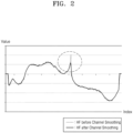
- FIG. 2 is a graph illustrating, in a comparative example, discontinuity of a beamforming matrix for each subcarrier corresponding to a signal beamformed by an access point.
- an access point may perform beamforming on a station on the basis of a feedback frame received from the station.
- the beamforming performed by the access point may be smooth beamforming.
- discontinuity may occur between beamforming matrices HF corresponding to certain adjacent subcarriers due to smooth beamforming.
- the access point may receive, from the station, a feedback frame including channel smoothing-related phase information, and may perform beamforming on the station by using the channel smoothing-related phase information, to prevent or reduce the large energy loss.
- FIG. 3 is a block diagram illustrating a wireless communication system 20 according to some example embodiments.
- the block diagram of FIG. 3 illustrates a beamformer 21 and a beamformee 22 communicating with each other in the wireless communication system 20.
- Each of the beamformer 21 and the beamformee 22 may be any apparatus communicating in the wireless communication system 20, and may be referred to as an apparatus for wireless communication.
- each of the beamformer 21 and the beamformee 22 may be an access point or a station of a WLAN system.
- the beamformer 21 may include a controller 21_1, a beamforming circuitry 21_2, and a plurality of first antennas AT_11 to AT_x1.
- the controller 21_1 and the beamforming circuitry 21_2 may be defined as a processing circuitry of the beamformer 21.
- the beamformee 22 may include a channel estimator 22_1, a decomposer 22_2, a phase information generator 22_3, a compressor 22_4, and a plurality of second antennas AT_12 to AT_y2.
- the channel estimator 22_1, the decomposer 22_2, the phase information generator 22_3, and the compressor 22_4 may be defined as a processing circuitry of the beamformee 22.
- the beamformee 22 will be first described.
- the beamformee 22 may receive an NDP via the plurality of second antennas AT_12 to AT_y2.
- the channel estimator 22_1 may estimate a channel by using a reference signal included in the received NDP.
- the NDP may also be referred to as a sounding packet.
- H k is a channel matrix
- x k is a transmission data stream
- n k may denote thermal noise.
- k may denote a subcarrier index of a channel, and may have a range of 1 to N FFT .
- the channel matrix H k may have a size of Nr ⁇ Nt for each subcarrier.
- Nr is the number of second antennas AT_12 to AT_y2
- Nt is the number of first antennas AT_11 to AT_x1.
- Each of the elements of Equation 1 may be defined as a matrix or a vector.
- the transmission data stream x k may have, for example, a size of Ns ⁇ 1.
- Ns is the number of transmission streams.
- the thermal noise n k may refer to white Gaussian noise.
- the thermal noise n k may have a size of Nr ⁇ 1.
- the channel estimator 22_1 may generate channel state information on the basis of the estimated channel.
- the channel state information may include at least one of a channel quality indicator (CQI), a precoding matrix indicator (PMI), and a rank indicator (RI).
- CQI channel quality indicator
- PMI precoding matrix indicator
- RI rank indicator
- the decomposer 22_2 may perform, as in Equation 2, singular value decomposition on the channel ⁇ est,k estimated by the channel estimator 22_1.
- H ⁇ est , k U k ⁇ k V k h
- Equation 2 U k is a left singular matrix, and V k is a right singular matrix and may include a Hermitian operator. ⁇ k may be a diagonal matrix including non-negative singular values.
- the left singular matrix U k may have a size of Nr ⁇ Nss.
- the right singular matrix V k may have a size of Ntx ⁇ Nss.
- ⁇ k may have a size of Nss ⁇ Nss.
- the right singular matrix V k may be referred to as an initial beam steering matrix.
- the beamformer 21 may transmit a signal to the beamformee 22 via orthogonal frequency division multiplexing (OFDM) modulation through which N FFT subcarriers in one symbol are guaranteed to have orthogonality with each other, and thus, a channel estimation operation of the channel estimator 22_1 and a singular value decomposition operation of the channel decomposer 22_2 may be performed for each subcarrier.
- OFDM orthogonal frequency division multiplexing
- the decomposer 22_2 may apply, to the initial beam steering matrix V k as in Equation 3, the diagonal matrix D for performing a common phase shift without intactly transmitting the initial beam steering matrix V k to the beamformer 21, to reduce feedback overhead transmitted to the beamformer 21.
- Q k V k D
- a first diagonal matrix D may be a matrix for allowing an element of a last row of each column of the beam steering matrix Q k to have a real value.
- the first diagonal matrix D may be ( e ⁇ j ⁇ N tx 1 , ... , e ⁇ j ⁇ N tx , N tx , and for example, e ⁇ j ⁇ N tx 1 may refer to a phase value of an element corresponding to a N tx th row and a first column of the initial beam steering matrix V k .
- the first diagonal matrix D may include a phase value of an element of a last row of each column of the initial beam steering matrix V k .
- the compressor 22_4 may acquire, as in Equations 4 to 6, angle information ⁇ , ⁇ regarding the beam steering matrix Q k generated via the decomposer 22_2.
- 1 i-1 is a vector including 1 having a length of i-1.
- ⁇ Ntx ⁇ Nss is an identity matrix having a size of Ntx ⁇ Nss.
- D i 1 i ⁇ 1 , e j ⁇ i , i , ... , e j ⁇ N r ⁇ 1 , i , 1 may be expressed as a second diagonal matrix as in Equation 5 below.
- D i 1 i ⁇ 1 , e j ⁇ i , i , ... , e j ⁇ N tx ⁇ 1 , i , 1 I i ⁇ 1 0 ... ... 0 0 e j ⁇ i , i 0 ... 0 ⁇ 0 0 ⁇ ⁇ 0 e j ⁇ N tx ⁇ 1 , i 0 0 0 0 0 0 1 ,
- G li ( ⁇ ) is a givens rotation matrix, and may be expressed as in Equation 6 below.
- G li ⁇ I i ⁇ 1 0 0 ... 0 0 cos ⁇ 0 s in ⁇ 0 0 0 0 0 I l ⁇ i ⁇ 1 0 0 0 ⁇ sin ⁇ 0 cos ⁇ 0 0 0 0 0 I Ntx ⁇ 1
- the compressor 22_4 may quantize the acquired angle information ⁇ , ⁇ .
- the phase information generator 22_3 may generate channel smoothing-related phase information by different methods according to the number of second antennas AT_12 to AT_y2. For example, when one second antenna is included, the phase information generator 22_3 may generate, as the channel smoothing-related phase information, phases of elements of the first diagonal matrix D used to generate the beam steering matrix Q k from the initial beam steering matrix V k . In the above method, the phase information generator 22_3 may generate, for each subcarrier, channel smoothing-related phase information including phases of the first diagonal matrices D.
- the phase information generator 22_3 may generate, as channel smoothing-related phase information, phases for minimizing a euclidean distance between beam steering matrices corresponding to adjacent subcarriers or for maximizing a cross-correlation between the beam steering matrices.
- the phase information generator 22_3 may generate, for each subcarrier, channel smoothing-related phase information including phases for maximizing a cross-correlation between beam steering matrices corresponding to adjacent subcarriers.
- phase information corresponding to the first subcarrier includes phases for maximizing a cross-correlation between beam steering matrices of the second subcarrier adjacent to a beam steering matrix of the first subcarrier.
- Phase information corresponding to the second subcarrier includes phases for maximizing a cross-correlation between beam steering matrices of the third subcarrier adjacent to the beam steering matrix of the second subcarrier.
- the phase information generator 22_3 may determine whether or not a channel smoothing-related condition is satisfied, by using the beam steering matrices Q k corresponding to subcarriers, which are acquired from the estimated channel ⁇ est,k . For example, the phase information generator 22_3 may sequentially determine whether or not subcarriers arranged on the basis of an index satisfy the channel smoothing-related condition. For example, the phase information generator 22_3 may determine, as a start subcarrier, a subcarrier that first satisfies the channel smoothing-related condition, and may omit determining whether or not subcarriers after the start subcarrier satisfy the channel smoothing-related condition.
- whether or not each subcarrier satisfies the channel smoothing-related condition may be determined on the basis of a relationship between the beam steering matrices Q k corresponding to adjacent subcarriers.
- the channel smoothing-related condition may include at least one of a first condition that an euclidean distance between the beam steering matrices Q k corresponding to adjacent subcarriers is greater than or equal to a first reference value, and a second condition that a cross-correlation between the beam steering matrices Q k corresponding to adjacent subcarriers is less than or equal to a second reference value.
- the phase information generator 22_3 may determine at least one of a plurality of criteria as the channel smoothing-related condition, on the basis of a communication state between the beamformer 21 and the beamformee 22. For example, when the communication state between the beamformer 21 and the beamformee 22 is poor, the phase information generator 22_3 may determine only one of the first condition and the second condition as the channel smoothing-related condition, and, when the communication state between the beamformer 21 and the beamformee 22 is of high quality, may determine the first condition and the second condition as the channel smoothing-related condition.
- the phase information generator 22_3 may generate channel smoothing-related phase information including pieces of phase information corresponding to a start subcarrier from among subcarriers, and the other subcarriers after the start subcarrier. A detailed structure of a feedback frame related to channel smoothing-related phase information will be described later.
- the compressor 22_4 may generate a feedback frame including the quantized angle information ⁇ , ⁇ and the channel smoothing-related phase information.
- the quantized angle information ⁇ , ⁇ may be referred to as information regarding the channel estimated by the channel estimator 22_1.
- the beamformee 22 may transmit the feedback frame to the beamformer 21 via a transceiver (not shown) of the beamformee 22 and the plurality of second antennas AT_12 to AT_y2.
- the beamformer 21 may receive the feedback frame from the beamformee 22 via a transceiver (not shown) and the plurality of first antennas AT_11 to AT_x1.
- the controller 21_1 may control the overall operation of the beamformer 21 for communication.
- the controller 21_1 may generate a null data packet announcement (NDPA) frame and an NDP, which will be described later, and may process information included in the feedback frame to be used by the beamforming circuitry 21_2.
- NDPA null data packet announcement
- NDP null data packet announcement
- the beamforming circuitry 21_2 may perform smooth beamforming on the beamformee 22, on the basis of the feedback frame.
- Performing beamforming may refer to an operation of determining a beamforming matrix for each subcarrier of a signal transmitted by the beamformer 21 to the beamformee 22.
- the beamforming circuitry 21_2 may perform a beamforming operation by reflecting the channel smoothing-related phase information in the angle information ⁇ , ⁇ of the feedback frame.
- the beamforming circuitry 21_2 may use the channel smoothing-related phase information to reduce discontinuity of beamforming matrices HF corresponding to adjacent subcarriers, as shown in FIG. 2 .
- the beamformer 21 may identify whether or not the feedback frame includes the channel smoothing-related phase information.
- the beamformer 21 may identify whether or not channel smoothing-related phase information is present, by identifying a particular field of the feedback frame or by identifying whether or not the channel smoothing-related phase information includes data indicating that the channel smoothing-related phase information is empty.
- the feedback frame includes the channel smoothing-related phase information, the following operation may be performed.
- the beamforming circuitry 21_2 may generate an initial beamforming matrix for each subcarrier by using the angle information ⁇ , ⁇ , and may generate a beamforming matrix for each subcarrier by applying the channel smoothing-related phase information to the initial beamforming matrix.
- the discontinuity of the beamforming matrices HF may occur by the beamformee 22 generating, as in Equation 3, the beam steering matrix Q k by using the first diagonal matrix D, and thus, the beamformer 21 may reduce discontinuity of beamforming matrices by receiving, from the beamformee 22, phase information related to the first diagonal matrix D and reflecting the received phase information on a beamforming operation.
- the beamformer 21 may transmit, to the beamformee 22 via the transceiver (not shown) and the first antennas AT_11 to AT_x1, a beamformed signal (or PPDU) according to the beamforming matrices determined by the beamforming circuitry 21_2. After performing channel smoothing on the beamformed signal, the beamformee 22 may process the beamformed signal.
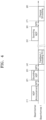
- FIG. 4 is a timing diagram illustrating channel sounding according to some example embodiments.
- the timing diagram of FIG. 4 illustrates channel sounding performed by a beamformer and a first beamformee.
- Channel sounding may be based on various protocol standards.
- the beamformer may be an access point, and the first beamformee may be a first station.
- FIG. 4 is only an example of some example embodiments, and thus, example embodiments are not limited to the channel sounding of FIG. 4 .
- the beamformer may transmit an NDPA frame to the first beamformee.
- the beamformer may transmit, to the first beamformee, the NDPA frame announcing transmission of a sounding NDP to acquire channel state information of a downlink.
- the NDPA frame may be a control frame, and the first beamformee may prepare for reception of the sounding NDP on the basis of the NDPA frame.
- the NDPA frame may include a subfield indicating whether or not the first beamformee is requested for first channel smoothing-related phase information PI1.
- the first beamformee may determine whether or not to feed the first channel smoothing-related phase information PI1 back to the beamformer, by identifying a value of the subfield of the NDPA frame.
- a detailed format of the NDPA frame will be described later with reference to FIG. 10 .
- the beamformer may transmit the sounding NDP to the first beamformee. For example, after transmitting the NDPA frame to the first beamformee, the beamformer may transmit the sounding NDP to the first beamformee after a short interframe space (SIFS) time.
- the first beamformee may estimate a first channel (or a first downlink channel) on the basis of the sounding NDP and generate information regarding the estimated first channel.
- the first beamformee may identify, via the subfield of the NDPA frame, that the first channel smoothing-related phase information PI1 is requested, and may generate the first channel smoothing-related phase information PI1.
- the sounding NDP may be interchangeably referred to as an NDP.
- the first beamformee may transmit a first feedback frame to the beamformer. For example, after an SIFS time from a time t31 after receiving the sounding NDP, the first beamformee may transmit, to the beamformer, the first feedback frame including information regarding the estimated first channel and the first channel smoothing-related phase information PI1.
- the beamformer may transmit a smooth beamformed PPDU to the first beamformee on the basis of beamforming matrices determined by performing smooth beamforming by reflecting the first channel smoothing-related phase information PI1 in the information regarding the estimated first channel.
- the first beamformee may perform channel smoothing on the smooth beamformed PPDU and then process the smooth beamformed PPDU.
- FIG. 5 is a message diagram illustrating a method for channel sounding according to some example embodiments.
- the message diagram of FIG. 5 illustrates operations of a beamformer 31, which is an access point, and a beamformee 32, which is one of a plurality of stations, over time.
- the method for channel sounding may include a plurality of operations S10 to S22.
- the beamformer 31 may generate an NDPA frame.
- the beamformer 31 may select, from among associated beamformees, one beamformee 32 to perform channel sounding (or provide beamforming), and may generate the NDPA frame on the basis of the selected beamformee 32.
- the NDPA frame may include a control frame, and the beamformee 32 may prepare for reception of an NDP on the basis of the NDPA frame.
- the NDPA frame may include a plurality of fields, and any one of the plurality of fields may include a subfield indicating whether or not the beamformee 32 is requested for channel smoothing-related phase information.
- the beamformer 31 may provide the NDPA frame to the beamformee 32.
- the beamformer 31 may transmit, to the beamformee 32, a PPDU including the NDPA frame generated in operation S10, and the beamformee 32 may receive, from the beamformer 31, the PPDU including the NDPA frame.
- the beamformer 31 may generate an NDP corresponding to the beamformee 32.
- the beamformee 32 may identify, via the NDPA frame, whether or not the beamformer 31 requests the channel smoothing-related phase information.
- the beamformee 32 may recognize a protocol standard corresponding to a current NDPA frame by identifying a version of the NDPA frame. Accordingly, the beamformee 32 may recognize a protocol standard corresponding to the NDP subsequently received from the beamformer 31.
- the beamformer 31 may provide the NDP to the beamformee 32.
- the beamformee 32 may identify the NDP. In other words, the beamformee 32 may extract pieces of information (or pieces of data) included in fields of the NDP transmitted thereto from the beamformer 31.
- the beamformee 32 may estimate a channel by using the pieces of information extracted from the fields of the NDP.
- the beamformee 32 may generate the channel smoothing-related phase information according to the number of antennas thereof.
- the beamformee 32 may generate phase information by different methods according to the number of antennas thereof. The detailed description thereof will be given below with reference to FIGS. 6 and 7 .
- the beamformee 32 may generate a feedback frame including information regarding the estimated channel and the channel smoothing-related phase information.
- the beamformee 32 may provide the feedback frame to the beamformer 31.
- the feedback frame may include a field in which the channel smoothing-related phase information is arranged, and a field including a subfield having a value indicating whether or not the channel smoothing-related phase information is present.
- the beamformer 31 may extract, from the feedback frame, the information regarding the estimated channel and the channel smoothing-related phase information, and may perform smooth beamforming by reflecting the channel smoothing-related phase information in the information regarding the estimated channel. For example, the beamformer 31 may identify, via some fields of the feedback frame, whether or not the channel smoothing-related phase information is present, and may acquire the channel smoothing-related phase information. For example, the beamformer 31 may acquire the channel smoothing-related phase information after identifying whether or not the channel smoothing-related phase information includes data indicating that the channel smoothing-related phase information is empty.
- the beamformer 31 may provide the beamformee 32 with a beamformed PPDU on the basis of beamforming matrices for each subcarrier, which are determined in operation S20.
- the beamformee 32 may perform channel smoothing on the beamforming matrices corresponding to the beamformed PPDU. Thereafter, the beamformee 32 may process the beamformed PPDU.
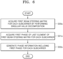
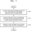
- FIGS. 6 and 7 are flowcharts illustrating some example embodiments of operation S17 of FIG. 5 .
- FIG. 6 illustrates that the beamformee 32 includes one antenna
- FIG. 7 illustrates that the beamformee 32 includes a plurality of antennas.
- FIGS. 6 and 7 are only embodiments, and the spirit of the inventive concepts are not limited thereto.
- FIG. 5 may be further referred to.
- the beamformee 32 may acquire an initial beam steering matrix for each subcarrier by performing singular value decomposition on an estimated channel.
- the beamformee 32 may acquire a first phase of a last element of the initial beam steering matrix for each subcarrier.
- the beamformee 32 may acquire a first phase of at least one element corresponding to a last row of each column of the initial beam steering matrix for each subcarrier.
- the beamformee 32 may generate channel smoothing-related phase information including the first phase for each subcarrier.
- the channel smoothing-related phase information may include information corresponding to the first diagonal matrix D described above with reference to FIG. 3 .
- the beamformee 32 may acquire a beam steering matrix for each subcarrier by performing singular value decomposition on an estimated channel. As described above with reference to FIG. 3 , the beam steering matrix may be generated from an initial beam steering matrix. In operation S31b, the beamformee 32 may acquire a second phase for minimizing an euclidean distance between adjacent beam steering matrices or maximizing a cross-correlation between adjacent beam steering matrices.
- the beamformee 32 may use an euclidean distance between beam steering matrices (e.g., , Q k- 1 and Q k ) of two adjacent subcarriers, which is obtained as in Equation 7.
- Equation 7 ⁇ is a norm operator, and D k opt in which the euclidean distance between the beam steering matrices (e.g., Q k -1 and Q k ) of adjacent subcarriers is minimized may be obtained.
- the beamformee 32 may use a cross-correlation between beam steering matrices (e.g., Q k -1 and Q k ) of two adjacent subcarriers, which is obtained as in Equation 8.
- D k opt in which a cross-correlation between beam steering matrices (e.g., Q k -1 and Q k ) of adjacent subcarriers is maximized may be obtained.
- a beamformee may generate second phases of elements of D k opt for each subcarrier as channel smoothing-related phase information.
- Equation 7 Solutions of Equation 7 and Equation 8 may be defined as in Equation 9.
- the second phases may include ⁇ i opt .
- the beamformee 32 may generate channel smoothing-related phase information including the second phases.
- FIGS. 8A and 8B are flowcharts illustrating some example embodiments of operation S17 of FIG. 5 .
- FIG. 5 may be further referred to.
- the beamformee 32 may determine, on the basis of an estimated channel, whether or not a channel smoothing-related condition is satisfied.
- the beamformee 32 may determine whether or not a channel smoothing-related condition is satisfied, on the basis of an euclidean distance between beam steering matrices (e.g., Q k -1 and Q k ) of two adjacent subcarriers, which is obtained as in Equation 10.
- M k 1 ⁇ Q k ⁇ 1 ⁇ Q k ⁇ M k 1 denotes an euclidean distance between beam steering matrices Q k and Q k -1 of each of a k th subcarrier and a k-1 st subcarrier adjacent thereto.
- the beamformee 32 may determine whether or not each subcarrier satisfies a first condition of Equation 11.
- the beamformee 32 may determine whether or not an euclidean distance M k 1 calculated for each subcarrier is greater than or equal to a first reference value TH 1 . When the euclidean distance M k 1 is greater than or equal to the first reference value TH 1 , the beamformee 32 determine that a corresponding subcarrier satisfies the channel smoothing-related condition.
- the beamformee 32 may determine whether or not the channel smoothing-related condition is satisfied, on the basis of a cross-correlation between beam steering matrices (e.g., Q k -1 and Q k ) of two adjacent subcarriers, which is obtained as in Equation 12.
- M k 2 XCor Q k ⁇ 1 Q k
- M k 2 denotes a cross-correlation between the beam steering matrices (Q k and Q k -1 ) of each of the k th subcarrier and the k-1 st subcarrier adjacent thereto.
- the beamformee 32 may determine whether or not each subcarrier satisfies a second condition of Equation 13.
- the beamformee 32 may determine whether or not the cross-correlation M k 2 calculated for each subcarrier is less than or equal to a second reference value TH 2 . When the cross-correlation M k 2 is less than or equal to the second reference value TH 2 , the beamformee 32 may determine that a corresponding subcarrier satisfies the channel smoothing-related condition.
- At least one of various conditions may be set as a channel smoothing-related condition.
- the beamformee 32 may generate channel smoothing-related phase information according to the number of antennas. In some example embodiments, the beamformee 32 may generate channel smoothing-related phase information including phase information generated for each subcarrier.
- the beamformee 32 may generate a feedback frame including information indicating whether or not the channel smoothing-related phase information is included.
- the beamformee 32 may arrange, in a first particular field of the feedback frame, the information indicating that the channel smoothing-related phase information is included, and may arrange the channel smoothing-related phase information in a second particular field of the feedback frame.
- the beamformee 32 may arrange, in the first particular field of the feedback frame, information indicating that the channel smoothing-related phase information is not included, and may arrange, in the second particular field of the feedback frame, data indicating that the channel smoothing-related phase information is empty information.
- the data may have a certain pattern agreed between the beamformee 32 and the beamformer 31. Operation S19 of FIG. 5 is subsequently performed.
- the beamformee 32 may select at least one of a plurality of conditions as a channel smoothing-related condition. In some example embodiments, the beamformee 32 may select at least one of a plurality of conditions as a channel smoothing-related condition on the basis of a communication state with the beamformer 31.
- the beamformee 32 may operate on the basis of a rougher channel smoothing-related condition by selecting only any one of a plurality of conditions as a channel smoothing-related condition when the communication state with the beamformer 31 is of high quality, and may operate on the basis of stricter channel smoothing-related conditions by selecting two or more of the plurality of conditions as channel smoothing-related conditions when the communication state with the beamformer 31 is poor.
- the beamformee 32 may select two or more of a plurality of conditions as channel smoothing-related conditions when the communication state with the beamformer 31 is of high quality, and may select only any one of the plurality of conditions as a channel smoothing-related condition when the communication state with the beamformer 31 is poor.
- the beamformee 32 may determine whether or not the channel smoothing-related condition is satisfied, on the basis of the channel smoothing-related condition determined in operation S17_1b.
- the beamformee 32 may generate channel smoothing-related phase information according to the number of antennas.
- the beamformee 32 may generate a feedback frame including information indicating whether or not the channel smoothing-related phase information is included. Operation S19 of FIG. 5 is subsequently performed.
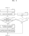
- FIG. 9 is a flowchart illustrating some example embodiments of operation S17 of FIG. 5 .
- FIG. 5 may be further referred to.
- the beamformee 32 sets n to 0.
- n denotes an index of a subcarrier, and m subcarriers may be arranged in index order.
- the beamformee 32 may select an n th subcarrier from among subcarriers.
- the beamformee 32 may determine whether or not the n th subcarrier satisfies a channel smoothing-related condition.
- the beamformee 32 may determine whether or not n is the same as m. When n is not the same as m in operation S17_4c, in operation S17_5c, the beamformee 32 may count up n, and may perform operation S17_2c.
- the beamformee 32 may determine the n th subcarrier as a start subcarrier.
- the beamformee 32 may generate channel smoothing-related phase information including pieces of phase information from the start subcarrier to a last subcarrier.
- the channel smoothing-related phase information may include information indicating the start subcarrier, and the pieces of phase information from the start subcarrier to the last subcarrier.
- the beamformee 32 may generate the channel smoothing-related phase information including data indicating that the channel smoothing-related phase information is empty information.
- Operation S19 of FIG. 5 is subsequently performed.
- FIG. 10 is a view illustrating an NDPA frame according to some example embodiments.
- the NDPA frame may include (e.g., may be implemented as) a media access control (MAC) header, a frame body, and/or a frame check sequence (FCS) field.
- the NDPA frame may include, in the MAC header, a frame control field, a duration field, an RA field, and a TA field, and may include, in the frame body, a sounding dialog token field and/or n STA information fields (wherein n is an integer greater than 0).
- the NDPA frame may include information used by beamformees to perform channel sounding.
- the frame control field may include information regarding a version of a MAC protocol and/or other additional control information.
- the duration field may include time information for setting a network allocation vector (NAV), or information regarding an identifier (e.g., an association identifier (AID)) of a user.
- NAV network allocation vector
- AID association identifier
- the RA field may include address information of a beamformee receiving the NDPA frame
- the TA field may include address information of a beamformer transmitting the NDPA frame.
- the sounding dialog token field may be referred to as a sounding sequence field, and may include identification information regarding the NDPA frame as described below.
- the STA information fields may be referred to as user information fields, and the NDPA frame may include first to n th STA information fields corresponding to first to n th beamformees receiving the NDPA frame.
- the first STA information field may include an AID11 field in which information regarding an identifier (AID11) for a first STA (or a first user) is arranged, a Partial BW Info field in which partial bandwidth information is arranged, a Smooth Beamformed field having arranged therein information regarding whether or not channel smoothing-related phase information is requested, an Nc field in which information regarding the number of subcarriers is arranged, a Feedback Type and Ng field in which information regarding a feedback type is arranged, a Disambiguration field, a Codebook Size field, and a Reserved field.
- AID11 information regarding an identifier
- Partial BW Info field in which partial bandwidth information is arranged
- a Smooth Beamformed field having arranged therein information regarding whether or not channel smoothing-related phase information is requested
- an Nc field in which information regarding the number of subcarriers is arranged
- a Feedback Type and Ng field in which information regarding a feedback type is arranged
- Disambiguration field a Codebook Size field
- a beamformee (or a station) subject to the first STA information field may identify, with reference to the Smooth Beamformed field, whether or not a beamformer requests channel smoothing-related phase information.
- a structure of the first STA information field may also be applied to structures of the other STA information fields.
- FIG. 11 is a table diagram illustrating information included in a feedback frame according to some example embodiments
- FIG. 12 is a view illustrating a structure of an EHT MIMO Control field of FIG. 11
- the feedback frame is based on an EHT protocol standard, but is only an example of some example embodiments. Therefore, the feedback frame is not limited thereto, and may be implemented in a format based on various protocol standards including an EHT+ protocol standard. Meanwhile, the detailed description of fields and subfields in FIGS. 11 and 12 is given in IEEE 802.11be, and thus is omitted herein.
- a feedback frame generated by a beamformee may include (e.g., may be implemented as) a Category field, an EHT Action field, an EHT MIMO Control field, an EHT Compressed Beamforming Report field, an EHT MU Exclusive Beamforming Report field, an EHT CQI Report field, and/or an EHT Smooth Beamforming Report field that are arranged in order.
- channel smoothing-related phase information generated by a beamformee may be arranged in the EHT Smooth Beamforming Report field.
- the EHT MIMO Control field may include an Nc Index subfield, an Nr Index subfield, a BW subfield, a Grouping subfield, a Codebook Information subfield, a Feedback Type subfield, a Remaining Feedback Segments subfield, a First Feedback Segment subfield, a Partial BW Info subfield, a Sounding Dialogue Token Number subfield, and/or a Smooth Beamformed subfield.
- the Smooth Beamformed subfield may have a value indicating whether or not phase information of the beamformee is present. For example, when the EHT Smooth Beamforming Report field includes phase information, the value of the Smooth Beamformed subfield may be set to 1.
- the value of the Smooth Beamformed subfield may be set to 0.
- a beamformer (or an access point) may identify, with reference to the EHT MIMO Control field of the feedback frame, whether or not the phase information of the beamformee is present, and may acquire the phase information from the EHT Smooth Beamforming Report field of the feedback frame when identifying that the phase information is present.
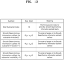
- FIG. 13 is a table diagram illustrating a structure of the EHT Smooth Beamforming Report field of FIG. 11 .
- the EHT Smooth Beamforming Report field may include a Start Subcarrier Index subfield and/or a Smooth Beamforming Information subfield for each subcarrier corresponding to channel smoothing-related phase information for each subcarrier.
- a size of the Start Subcarrier Index subfield may be set to 16 bits.
- the size of the Start Subcarrier Index subfield is only an example of some example embodiments, and is not limited thereto. Therefore, the size of the Start Subcarrier Index subfield may be set to match the number of subcarriers used for communication between the beamformer and the beamformee.
- the Smooth Beamforming Information subfield for each subcarrier may be set to bits corresponding to a result obtained by dividing, by 2, the product between the number N c of subcarriers and the number b ⁇ of bits of channel smoothing-related phase information of a corresponding subcarrier.
- the beamformer may identify a start subcarrier satisfying a channel smoothing-related condition by referring to the Start Subcarrier Index subfield, and may acquire channel smoothing-related phase information from the Smooth Beamforming Information subfields corresponding to the start subcarrier and subcarriers after the start subcarrier.
- the beamformer may perform smooth beamforming on the basis of the acquired channel smoothing-related phase information.
- FIG. 14 is a table diagram illustrating a structure of the EHT Smooth Beamforming Report field of FIG. 11 .
- channel smoothing-related phase information included in the EHT Smooth Beamforming Report field may include information regarding a size of an initial beam steering matrix V (or a beam steering matrix Q), information regarding the number of angles (or phases), and/or phase values for respective subcarriers.
- N r may denote the number of antennas of a beamformee
- N c may denote the number of subcarriers
- k may denote an index of a subcarrier.
- the channel smoothing-related phase information of FIG. 14 may be arranged according to the EHT Smooth Beamforming Report field described above with reference to FIG. 13 .
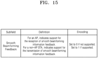
- FIG. 15 is a table diagram illustrating a subfield of an EHT PHY Capabilities Information field indicating whether or not smooth beamforming feedback may be supported, according to some example embodiments. Whether or not smooth beamforming feedback may be supported indicates whether or not a beamformer may request a feedback frame including channel smoothing-related phase information according to some example embodiments, and whether or not a beamformee may generate the feedback frame.
- the EHT PHY Capabilities Information field defined in the standard protocol of IEEE 802.11be may include a subfield indicating whether or not smooth beamforming feedback may be supported. For example, when the beamformer may support reception of smooth beamforming information feedback including channel smoothing-related phase information, the corresponding subfield may be set to 1. In addition, as an example, when a beamformee, which may support transmission of smooth beamforming information feedback including channel smoothing-related phase information, is not present, the corresponding subfield may be set to 0.
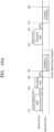
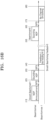
- FIGS. 16A and 16B are timing diagrams illustrating channel sounding in detail, according to some example embodiments.
- a beamformer may transmit an NDPA frame to a first beamformee.
- the NDPA frame may include a Smooth Beamformed field that may be set to 1 to request the first channel smoothing-related phase information PI1' from the first beamformee.
- the beamformer may transmit a sounding NDP to the first beamformee.
- the beamformer may transmit the sounding NDP to the first beamformee after an SIFS time.
- the first beamformee may estimate a first channel on the basis of the sounding NDP and generate information regarding the estimated first channel.
- the first beamformee may determine, on the basis of the estimated first channel, whether or not a channel smoothing-related condition is satisfied, and may generate the first channel smoothing-related phase information PI1' on the basis of a result of the determination.
- the first beamformee may transmit, to the beamformer, a first feedback frame including the first channel smoothing-related phase information PI1'.
- the beamformer may transmit a smooth beamformed PPDU to the first beamformee, on the basis of matrices determined by performing smooth beamforming on the basis of the first channel smoothing-related phase information PI1'.
- the beamformer may set a Beamformed field of the PPDU to 1 to notify the first beamformee that the corresponding PPDU is smooth beamformed.
- the first beamformee may perform channel smoothing on the smooth beamformed PPDU by identifying that the Beamformed field of the PPDU is 0, and then may process the smooth beamformed PPDU.
- a beamformer may transmit an NDPA frame to a first beamformee.
- the NDPA frame may include a Smooth Beamformed field that may be set to 1 to request first channel smoothing-related phase information PI1' from the first beamformee.
- the beamformer may transmit a sounding NDP to the first beamformee. After transmitting the NDPA frame to the first beamformee, the beamformer may transmit the sounding NDP to the first beamformee after an SIFS time.
- the first beamformee may estimate a first channel on the basis of the sounding NDP and generate information regarding the estimated first channel. Meanwhile, when the Smooth Beamforming Feedback subfield of FIG. 15 related to the first beamformee is set to 0, the first beamformee may not generate the channel smoothing-related phase information PI1'.
- the first beamformee may transmit, to the beamformer, a first feedback frame not including the first channel smoothing-related phase information PI1'.
- the first feedback frame may include only the information regarding the estimated first channel.
- the beamformer may transmit a smooth beamformed PPDU to the first beamformee on the basis of matrices determined by performing smooth beamforming on the basis of the first feedback frame.
- the beamformer may set a Beamformed field of the PPDU to 0 to notify the first beamformee that the corresponding PPDU is not smooth beamformed, to prevent the first beamformee from performing channel smoothing.
- the first beamformee may process the smooth beamformed PPDU without performing channel smoothing on the smooth beamformed PPDU by identifying that the Beamformed field of the PPDU is 0.
- FIGS. 16A and 16B are only embodiments, and thus, the spirit of the inventive concepts are not limited thereto.
- FIG. 17 is a timing diagram illustrating channel sounding according to some example embodiments.
- the timing diagram of FIG. 17 illustrates channel sounding performed by a beamformer and first to n th beamformees (wherein n is an integer greater than 1).
- the first to n th beamformees may support the same or different protocol standards, respectively.
- the beamformer may be an access point, and each of the first to n th beamformees may be a station. Embodiments are not limited to the channel sounding of FIG. 17 .
- the beamformer may transmit an NDPA frame to the first to n th beamformees.
- the first to n th beamformees may prepare for reception of a sounding NDP on the basis of the NDPA frame.
- the NDPA frame may include subfields indicating whether or not the first to n th beamformees are requested for first to n th channel smoothing-related phase information PI1 to PIn.
- the beamformer may transmit the sounding NDP to the first to n th beamformees. For example, after transmitting the NDPA frame to the first to n th beamformees, the beamformer may transmit the sounding NDP to the first to n th beamformees after an SIFS time.
- the sounding NDP may include first to n th NDPs corresponding to the first to n th beamformees, respectively, and the first to n th NDPs may be aggregated in different bands.
- the first to n th beamformees may estimate first to n th channels (or first to n th downlink channels), respectively, on the basis of the sounding NDP, and may generate information regarding the estimated first to n th channels.
- the first to n th beamformees may respectively identify, from subfields of the NDPA frame, that the first to n th channel smoothing-related phase information PI1 to PIn are requested, and may generate the first to n th channel smoothing-related phase information PI1 to PIn, respectively.
- some of the first to n th beamformees may not support an operation of generating channel smoothing-related phase information or a channel smoothing operation, and in this case, some of the first to n th beamformees may generate a feedback frame not including corresponding channel smoothing-related phase information.
- the beamformer may transmit a beamforming report poll (BFRP) trigger frame to the first to n th beamformees.
- BFRP beamforming report poll
- the access point may provide, after an SIFS time, the first to n th beamformees with the BFRP trigger frame for triggering uplink transmissions of the first to n th beamformees.
- the BFRP trigger frame may include information needed for the first to n th beamformees to transmit the feedback frame to the beamformer, e.g., the access point.
- the BFRP trigger frame may include information regarding resources to be used in uplink transmission.
- the first to n th beamformees may transmit first to n th feedback frames to the beamformer.
- At least one of the first to n th feedback frames may include channel smoothing-related phase information according to the above-described embodiments.
- the first to n th feedback frames may be aggregated in different bands.
- the first to n th feedback frames may be transmitted in bands corresponding to bands in which first to n th NDPs are transmitted.
- the first feedback frame may be transmitted in a band in which the first NDP is transmitted.
- the beamformer may transmit a smooth beamformed PPDU to the first to n th beamformees on the basis of beamforming matrices determined by performing smooth beamforming on the first to n th beamformees by using the first to n th channel smoothing-related phase information PI1 to PIn included in the first to n th feedback frames.
- the smooth beamformed PPDU may include first to n th PPDUs corresponding to the first to n th beamformees, respectively, and the first to n th PPDUs may be aggregated in different bands.
- the first to n th beamformees may perform channel smoothing on the first to n th PPDUs, respectively.
- a beamformee which does not support channel smoothing, may not perform channel smoothing.
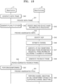
- FIG. 18 is a message diagram illustrating a method for channel sounding according to some example embodiments. As illustrated in FIG. 18 , the method for channel sounding may include a plurality of operations S40 to S52.
- a beamformer 41 may generate an NDPA frame.
- the beamformer 41 may select, from among associated beamformees, a plurality of beamformees 42 to perform channel sounding, and may generate the NDPA frame on the basis of the selected beamformees 42.
- the NDPA frame may include subfields indicating whether or not each of the beamformees 42 is requested for channel smoothing-related phase information.
- the beamformer 41 may provide the NDPA frame to the beamformees 42.
- the beamformer 41 may generate a plurality of NDPs corresponding to the beamformees 42, respectively.
- the beamformees 42 may respectively identify, with reference to the NDPA frame, whether or not the beamformer 41 requests the channel smoothing-related phase information from the beamformees 42.
- the beamformer 41 may provide the beamformees 42 with NDPs respectively aggregated in different bands.
- each of the beamformees 42 may identify an NDP thereof from among the aggregated NDPs.
- each of the beamformees 42 may estimate a channel thereof by using the identified NDP thereof.
- each of the beamformees 42 may generate a feedback frame.
- the beamformees 42 may provide the beamformer 41 with feedback frames aggregated in different bands, respectively.
- the beamformer 41 may perform, on the basis of the feedback frames, smooth beamforming on the beamformees 42.
- the beamformer 41 may perform smooth beamforming reflecting channel smoothing-related phase information, with respect to a feedback frame including the channel smoothing-related phase information.
- the beamformer 41 may provide, on the basis of beamforming matrices determined in operation S50, the beamformees 42 with a PPDU in which a plurality of PPDUs are respectively aggregated in different bands.
- a beamformee which may support channel smoothing, may perform channel smoothing on the PPDU thereof.
- FIG. 19 is a conceptual diagram illustrating an Internet of Things (IoT) network system 1000 to which some example embodiments are applied.
- IoT Internet of Things
- the IoT network system 1000 may include a plurality of IoT apparatuses 1100, 1120, 1140, and 1160, an access point 1200, a gateway 1250, a wireless network 1300, and a server 1400.
- the IoT may refer to a network between things using wired/wireless communication.
- Each of the IoT apparatuses 1100, 1120, 1140, and 1160 may form a group according to characteristics of each IoT apparatus. For example, IoT apparatuses may be grouped into a home gadget group 1100, a home appliance/furniture group 1120, an entertainment group 1140, a vehicle group 1160, and the like.
- the plurality of IoT apparatuses 1100, 1120, 1140, and 1160 may be connected to a communication network or connected to other IoT apparatuses via the access point 1200.
- the access point 1200 may be embedded in one IoT apparatus.
- the gateway 1250 may change a protocol to connect the access point 1200 to an external wireless network.
- the IoT apparatuses 1100, 1120, 1140, and 1160 may be connected to an external communication network via the gateway 2250.
- the wireless network 1300 may include the Internet and/or a public network.
- the plurality of IoT apparatuses 1100, 1120, 1140, and 1160 may be connected via the wireless network 1300 to the server 1400 providing a certain service, and a user may use the service via at least one of the plurality of IoT apparatuses 1100, 1120, 1140, and 1160.
- the plurality of IoT apparatuses 1100, 1120, 1140, and 1160 may transmit and receive channel smoothing-related phase information to and from each other, and may perform smooth beamforming on the basis of the channel smoothing-related phase information. Accordingly, the IoT apparatuses 1100, 1120, 1140, and 1160 may provide a high-quality service to the user by performing efficient and effective communication.
- processing circuitry may refer to, for example, hardware including logic circuits; a hardware/software combination such as a processor executing software; or a combination thereof.
- the processing circuitry more specifically may include, but is not limited to, a central processing unit (CPU), an arithmetic logic unit (ALU), a digital signal processor, a microcomputer, a field programmable gate array (FPGA), a System-on-Chip (SoC), a programmable logic unit, a microprocessor, application-specific integrated circuit (ASIC), etc.
- CPU central processing unit
- ALU arithmetic logic unit
- DSP digital signal processor
- microcomputer a field programmable gate array
- FPGA field programmable gate array
- SoC System-on-Chip
- ASIC application-specific integrated circuit
- Embodiments may be described with reference to acts and symbolic representations of operations (e.g., in the form of flow charts, flow diagrams, data flow diagrams, structure diagrams, block diagrams, etc.) that may be implemented in conjunction with units and/or devices discussed in more detail below.
- a function or operation specified in a specific block may be performed differently from the flow specified in a flowchart, flow diagram, etc.
- functions or operations illustrated as being performed serially in two consecutive blocks may actually be performed concurrently, simultaneously, contemporaneously or in some cases be performed in reverse order.
- the term "and/or" includes any and all combinations of one or more of the associated listed items.
Landscapes
- Engineering & Computer Science (AREA)
- Computer Networks & Wireless Communication (AREA)
- Signal Processing (AREA)
- Physics & Mathematics (AREA)
- Mathematical Physics (AREA)
- Power Engineering (AREA)
- Radio Transmission System (AREA)
- Mobile Radio Communication Systems (AREA)
Applications Claiming Priority (2)
| Application Number | Priority Date | Filing Date | Title |
|---|---|---|---|
| KR20220024577 | 2022-02-24 | ||
| KR1020220085875A KR20230127122A (ko) | 2022-02-24 | 2022-07-12 | 채널 사운딩을 위한 장치 및 방법 |
Publications (1)
| Publication Number | Publication Date |
|---|---|
| EP4236099A1 true EP4236099A1 (de) | 2023-08-30 |
Family
ID=85381494
Family Applications (1)
| Application Number | Title | Priority Date | Filing Date |
|---|---|---|---|
| EP23158203.2A Pending EP4236099A1 (de) | 2022-02-24 | 2023-02-23 | Vorrichtung und verfahren zur kanalmessung |
Country Status (3)
| Country | Link |
|---|---|
| US (1) | US12425270B2 (de) |
| EP (1) | EP4236099A1 (de) |
| TW (1) | TW202344010A (de) |
Families Citing this family (1)
| Publication number | Priority date | Publication date | Assignee | Title |
|---|---|---|---|---|
| CN121193293A (zh) * | 2024-06-20 | 2025-12-23 | 华为技术有限公司 | 一种通信方法和装置 |
Citations (3)
| Publication number | Priority date | Publication date | Assignee | Title |
|---|---|---|---|---|
| US20170331534A1 (en) * | 2016-05-10 | 2017-11-16 | Feng Jiang | Beamforming smoothing and indication |
| KR20220024577A (ko) | 2019-06-20 | 2022-03-03 | 유씨비 바이오파마 에스알엘 | 단백질 시료 중 응집제의 hplc 기반 검출 |
| KR20220085875A (ko) | 2020-12-15 | 2022-06-23 | 에이테크솔루션(주) | 파팅라인이 없는 사출 성형품 제조장치 |
Family Cites Families (13)
| Publication number | Priority date | Publication date | Assignee | Title |
|---|---|---|---|---|
| CN101588335B (zh) | 2008-05-19 | 2012-07-04 | 三星电子株式会社 | 利用信道相关性的mimo检测方法及系统 |
| US8139693B2 (en) * | 2008-10-28 | 2012-03-20 | Industrial Technology Research Institute | Apparatus and method for estimating inter-carrier interference power and noise power in a channel |
| US20120082193A1 (en) * | 2010-08-25 | 2012-04-05 | Qualcomm Incorporated | Beamforming feedback options for mu-mimo |
| WO2014179794A1 (en) | 2013-05-03 | 2014-11-06 | Marvell World Trade Ltd. | Beam change and smoothing recommendation in mixed mode wlan systems |
| KR20160041007A (ko) | 2014-10-06 | 2016-04-15 | 뉴라컴 인코포레이티드 | 고효율 무선랜에서 빔포밍된 전송 |
| KR102517669B1 (ko) | 2018-06-27 | 2023-04-05 | 삼성전자주식회사 | 무선 통신 방법 및 장치 |
| US10998944B2 (en) * | 2018-09-14 | 2021-05-04 | Samsung Electronics Co., Ltd. | System and method for applying smoothed beamforming |
| KR102735860B1 (ko) | 2020-03-03 | 2024-11-28 | 삼성전자주식회사 | 빔 송신 장치 및 그 동작 방법 |
| CN113765831A (zh) * | 2020-06-05 | 2021-12-07 | 华为技术有限公司 | Ppdu的传输方法及相关装置 |
| WO2022097958A1 (ko) * | 2020-11-06 | 2022-05-12 | 엘지전자 주식회사 | 무선랜 시스템에서 피드백 프레임을 송신하는 방법 및 장치 |
| US11799529B2 (en) * | 2020-12-16 | 2023-10-24 | Samsung Electronics Co., Ltd | Device and method of performing subcarrier grouping and/or codebook size selection in real-time for beamforming feedback and wireless communication system including the same |
| US12526648B2 (en) * | 2021-04-22 | 2026-01-13 | Samsung Electronics Co., Ltd. | Apparatus and method for channel sounding |
| WO2022261104A1 (en) * | 2021-06-07 | 2022-12-15 | Interdigital Patent Holdings, Inc. | Enhanced channel sounding reports for wlan systems |
-
2023
- 2023-02-23 EP EP23158203.2A patent/EP4236099A1/de active Pending
- 2023-02-24 TW TW112107037A patent/TW202344010A/zh unknown
- 2023-02-24 US US18/174,010 patent/US12425270B2/en active Active
Patent Citations (3)
| Publication number | Priority date | Publication date | Assignee | Title |
|---|---|---|---|---|
| US20170331534A1 (en) * | 2016-05-10 | 2017-11-16 | Feng Jiang | Beamforming smoothing and indication |
| KR20220024577A (ko) | 2019-06-20 | 2022-03-03 | 유씨비 바이오파마 에스알엘 | 단백질 시료 중 응집제의 hplc 기반 검출 |
| KR20220085875A (ko) | 2020-12-15 | 2022-06-23 | 에이테크솔루션(주) | 파팅라인이 없는 사출 성형품 제조장치 |
Also Published As
| Publication number | Publication date |
|---|---|
| TW202344010A (zh) | 2023-11-01 |
| US12425270B2 (en) | 2025-09-23 |
| US20230269116A1 (en) | 2023-08-24 |
Similar Documents
| Publication | Publication Date | Title |
|---|---|---|
| US10778294B2 (en) | Channel state information feedback method, terminal device, and network device | |
| US12224817B2 (en) | Apparatus and method of uplink beamforming in wireless local area network system | |
| US12563576B2 (en) | Triggering beamformed up link physical layer protocol data units | |
| EP4080784A1 (de) | Kanalsondierungsvorrichtung und -verfahren | |
| US20200028554A1 (en) | Method for Precoding Matrix Indicator Feedback and Apparatus | |
| US20180191410A1 (en) | Subset of w2 method and apparatus for sending precoding information and feeding back precoding information | |
| US9048896B2 (en) | Apparatus for multi-user multi-antenna transmission based on double codebook and method for the same | |
| EP4113885B1 (de) | Kanalsondierungsvorrichtung und -verfahren | |
| US11616542B2 (en) | Channel-matrix reduction for precoding control | |
| WO2017101586A1 (en) | System and method for quantization of angles for beamforming feedback | |
| EP4236099A1 (de) | Vorrichtung und verfahren zur kanalmessung | |
| US11575414B2 (en) | First communication apparatus, second communication apparatus, method, program, recording medium, and system | |
| KR20230127122A (ko) | 채널 사운딩을 위한 장치 및 방법 | |
| JP6108554B2 (ja) | 無線通信装置及び無線通信方法 | |
| KR20220145729A (ko) | 채널 사운딩을 위한 장치 및 방법 | |
| US20250158852A1 (en) | Apparatus and method for channel sounding | |
| US20250183945A1 (en) | Apparatus and method for channel sounding | |
| US20260122517A1 (en) | Apparatus and method for determining channel type based on machine learning and adaptive transmission based on channel type | |
| JP2026504744A (ja) | 通信の方法及びデバイス | |
| CN118101004A (zh) | 一种预编码方法、通信装置及存储介质 | |
| CN119544008A (zh) | 信道状态信息报告确定方法与装置、终端设备和网络设备 | |
| KR20220068890A (ko) | Wlan 시스템에서 상향링크 빔포밍을 위한 장치 및 방법 | |
| KR20120072330A (ko) | 통신 시스템에서 데이터 송수신 장치 및 방법 |
Legal Events
| Date | Code | Title | Description |
|---|---|---|---|
| PUAI | Public reference made under article 153(3) epc to a published international application that has entered the european phase |
Free format text: ORIGINAL CODE: 0009012 |
|
| STAA | Information on the status of an ep patent application or granted ep patent |
Free format text: STATUS: REQUEST FOR EXAMINATION WAS MADE |
|
| 17P | Request for examination filed |
Effective date: 20230223 |
|
| AK | Designated contracting states |
Kind code of ref document: A1 Designated state(s): AL AT BE BG CH CY CZ DE DK EE ES FI FR GB GR HR HU IE IS IT LI LT LU LV MC ME MK MT NL NO PL PT RO RS SE SI SK SM TR |
|
| P01 | Opt-out of the competence of the unified patent court (upc) registered |
Effective date: 20231212 |
|
| STAA | Information on the status of an ep patent application or granted ep patent |
Free format text: STATUS: EXAMINATION IS IN PROGRESS |
|
| 17Q | First examination report despatched |
Effective date: 20260202 |