EP4236107A2 - Blocage automatique de sortie pour systèmes répéteurs actifs - Google Patents
Blocage automatique de sortie pour systèmes répéteurs actifs Download PDFInfo
- Publication number
- EP4236107A2 EP4236107A2 EP23180228.1A EP23180228A EP4236107A2 EP 4236107 A2 EP4236107 A2 EP 4236107A2 EP 23180228 A EP23180228 A EP 23180228A EP 4236107 A2 EP4236107 A2 EP 4236107A2
- Authority
- EP
- European Patent Office
- Prior art keywords
- repeater
- circuitry
- power level
- state
- operated
- Prior art date
- Legal status (The legal status is an assumption and is not a legal conclusion. Google has not performed a legal analysis and makes no representation as to the accuracy of the status listed.)
- Pending
Links
Images


Classifications
-
- H—ELECTRICITY
- H04—ELECTRIC COMMUNICATION TECHNIQUE
- H04B—TRANSMISSION
- H04B7/00—Radio transmission systems, i.e. using radiation field
- H04B7/14—Relay systems
- H04B7/15—Active relay systems
- H04B7/155—Ground-based stations
- H04B7/15507—Relay station based processing for cell extension or control of coverage area
-
- H—ELECTRICITY
- H04—ELECTRIC COMMUNICATION TECHNIQUE
- H04B—TRANSMISSION
- H04B7/00—Radio transmission systems, i.e. using radiation field
- H04B7/14—Relay systems
- H04B7/15—Active relay systems
- H04B7/155—Ground-based stations
- H04B7/15557—Selecting relay station operation mode, e.g. between amplify and forward mode, decode and forward mode or FDD - and TDD mode
-
- H—ELECTRICITY
- H04—ELECTRIC COMMUNICATION TECHNIQUE
- H04B—TRANSMISSION
- H04B7/00—Radio transmission systems, i.e. using radiation field
- H04B7/14—Relay systems
- H04B7/15—Active relay systems
- H04B7/155—Ground-based stations
- H04B7/15528—Control of operation parameters of a relay station to exploit the physical medium
- H04B7/15535—Control of relay amplifier gain
-
- H—ELECTRICITY
- H04—ELECTRIC COMMUNICATION TECHNIQUE
- H04B—TRANSMISSION
- H04B7/00—Radio transmission systems, i.e. using radiation field
- H04B7/24—Radio transmission systems, i.e. using radiation field for communication between two or more posts
- H04B7/26—Radio transmission systems, i.e. using radiation field for communication between two or more posts at least one of which is mobile
- H04B7/2603—Arrangements for wireless physical layer control
- H04B7/2606—Arrangements for base station coverage control, e.g. by using relays in tunnels
-
- H—ELECTRICITY
- H04—ELECTRIC COMMUNICATION TECHNIQUE
- H04W—WIRELESS COMMUNICATION NETWORKS
- H04W84/00—Network topologies
- H04W84/02—Hierarchically pre-organised networks, e.g. paging networks, cellular networks, WLAN [Wireless Local Area Network] or WLL [Wireless Local Loop]
- H04W84/04—Large scale networks; Deep hierarchical networks
- H04W84/042—Public Land Mobile systems, e.g. cellular systems
- H04W84/047—Public Land Mobile systems, e.g. cellular systems using dedicated repeater stations
Definitions
- a repeater system (such as a distributed antenna system (DAS) or a single-node repeater) is typically used to improve the wireless radio frequency (RF) coverage provided by one or more base stations.
- the wireless service provided by each base station can include commercial cellular service or private or public safety wireless service.
- the repeater system can be implemented as an "active" system in the sense that the downlink and uplink RF signals are amplified before being repeated.
- Active repeater systems can be used, for example, in sport stadiums, buildings (hotels, malls, or trade centers), metro stations and airports, trains, and tunnels.
- Each base station can be coupled to the repeater system via one or more cables or via a wireless connection, for example, using one or more donor antennas.
- Repeater systems can be used in other applications.
- each base station coupled to a repeater system can be dedicated to the repeater system.
- the capacity of each base station coupled to a repeater system can also be shared among the repeater system and a base station antenna system that is co-located with the base station and/or shared among the repeater system and one or more other repeater systems.
- Each active element in each transmit signal path of the repeater system adds noise to the repeated RF signal transmitted from the signal path.
- Noise contribution at the receiver of the base station can be too high if the path loss (attenuation) between the repeater system and the base station is too low due to short distances between the donor antenna and the co-located base station antenna (for example, low free space loss), low coupling values between the repeater system and the base station (for example, where there is a cable connection between the repeater system and the base station).
- Noise contribution at the receiver of the based station can be too high if the noise figure (NF) of the repeater system is too high, if gain setting of the repeater system is too high (for example, resulting in amplified noise), or if multiple repeater systems share the capacity of one base station.
- NF noise figure
- One embodiment is directed to a repeater system for use with a base station that implements a wireless interface that makes use of control transmissions that are retransmittable.
- the system comprises repeater circuitry configured to, while operating in an unmuted state, output a repeated signal at a first power level.
- the repeated signal is an amplified version of an original signal received by the repeater system.
- the repeater circuitry is configured to, while operating in a muted state, one of: output the repeated signal at a power level that is less than the first power level; or not output the repeated signal.
- the repeater system further comprises a power level detection function configured to determine a received power level of the original signal received by the repeater system.
- the repeater system is configured to, while the repeater circuitry is operated in the unmuted state with the timer running, stop the running of the timer and have the repeater circuitry continue to be operated in the unmuted state, in response to the received power level exceeding the first threshold value in connection with a subsequent control transmission.
- the repeater system is configured to, while the repeater circuitry is operated in the unmuted state with the timer running, stop the running of the timer and transition the repeater circuitry to being operated in the muted state, in response to the timer having run for a predetermined amount of time without the received power level exceeding the first threshold value.
- the method comprises, while the repeater circuitry is operated in the muted state, transitioning the repeater circuitry to being operated in the unmuted state, in response to the received power level exceeding a first threshold value in connection with a first control transmission.
- the method further comprises, while the repeater circuitry is operated in the unmuted state with a timer not running, starting the running of the timer and having the repeater circuitry continue to be operated in the unmuted state, in response to the received power level falling below a second threshold value in connection with the completion of the transmission of the first control transmission.
- the method further comprises, while the repeater circuitry is operated in the unmuted state with the timer running, stopping the running of the timer and having the repeater circuitry continue to be operated in the unmuted state, in response to the received power level exceeding the first threshold value in connection with a subsequent control transmission.
- the method further comprises, while the repeater circuitry is operated in the unmuted state with the timer running, stopping the running of the timer and transitioning the repeater circuitry to being operated in the muted state, in response to the timer having run for a predetermined amount of time without the received power level exceeding the first threshold value.
- the system comprises repeater circuitry configured to, while operating in an unmuted state, output a repeated signal at a first power level.
- the repeated signal is an amplified version of an original signal received by the repeater system.
- the repeater circuitry is configured to, while operating in a muted state, one of: output the repeated signal at a power level that is less than the first power level or not output the repeated signal.
- the repeater system further comprises a power level detection function configured to determine a received power level of a signal received by the repeater system.
- Another embodiment is directed to a method of muting a repeater system used with a base station.
- the repeater system comprising repeater circuitry configured to, while operating in an unmuted state, output a repeated signal at a first power level.
- the repeated signal is an amplified version of an original signal received by the repeater system.
- the repeater circuitry is configured to, while operating in a muted state, do one of: output the repeated signal at a power level that is less than the first power level or not output the repeated signal.
- the repeater system is configured to determine a received power level of a signal received by the repeater system.
- the method comprises, while the repeater circuitry is operated in the muted state, performing a transition process for operating the repeater circuitry in the unmuted state, in response to the received power level crossing a first threshold value.
- the method further comprises, while the repeater circuitry is operated in the unmuted state, performing a transition process for operating the repeater circuitry in the muted state, in response to the received power level crossing a second threshold value.
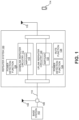
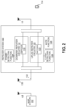
- the repeater system 100 is coupled to one or more base stations 102 and is configured to improve the wireless coverage provided by the base stations 102.
- each base station coupled to a repeater system can be dedicated to the repeater system or can be shared among the repeater systems and a base station antenna system that is co-located with the base station and/or one or more repeater systems.
- the repeater system 100 comprises uplink repeater circuitry 120 that is configured to receive one or more uplink radio frequency signals transmitted from the user equipment 114. These signals are analog radio frequency signals and are also referred to here as "LTE uplink radio frequency signals.” Each UE uplink radio frequency signal includes one or more radio frequency channels used for communicating in the uplink direction with user equipment 114 over the relevant wireless air interface.
- the repeater system 100 is configured to implement a power detection function 124 that detects and quantifies the power level of signals received at the repeater system 100 in either or both of the uplink or downlink.
- the power detection function 124 can be implemented to separately detect and quantify the received power for the relevant downlink and uplink frequency bands for each base station 102 associated with the repeater system 100.
- the power detection function 124 can be implemented in other ways.
- the repeater system 100 is also configured to implement a mute function 126.
- the mute function 126 is configured to transition the repeater circuity 112 and/or 120 among at least a muted state and an unmuted state for the uplink and/or downlink frequency bands for each base station 102 associated with the repeater system 100.
- the repeater circuitry 112 and/or 120 can include one or more switches that can be switched so that, when the repeater circuitry 112 or 120 is placed in the muted state for a given base station 102, the repeater circuitry 112 or 120 does not output the relevant repeated signals and so that, when the repeater circuitry 112 or 120 is placed in the unmuted state for a given base station 102, the repeater circuitry 112 or 120 outputs the relevant repeated signal at normal power levels.
- amplifiers (and other active elements in the repeater circuitry 112 or 120) used for outputting the repeated signals for a given base station 102 are powered down when the repeater circuitry 112 or 120 is placed in the muted state for that base station 102, in which case those powered-down amplifiers and other active elements would be powered-on when the repeater circuitry 112 or 120 is placed in the unmuted state for that base station 102.
- the repeater circuitry 112 or 120 and the mute function 126 can be implemented in other ways. For example, instead of being configured to not output the repeated signals when in the muted state, the repeater circuitry 112 or 120 can be configured to output the repeated signals but at a reduced power level when in the muted state.
- the RACH procedures specify that, in the event that an initial RACH transmission is not successfully received by the relevant base station, the RACH transmission is retransmitted.
- LTE Long Term Evolution
- 3GPP 3rd Generation Partnership Project
- a RACH procedure is used by the UE 114 to access the wireless network.
- the access procedure is initiated by the UE 114 transmitting data on a Physical Random Access Channel (PRACH) defined by the LTE standards.
- PRACH Physical Random Access Channel
- the above equation means that the initial PRACH transmit power of the UE 114 the lesser of the maximum available transmit power of the LTE 114 and the sum of the target receive power for the base station 102 and the path loss.
- such a simplified mute function 126 can be implemented using a first comparator that compares an output of the power detection function 124 with a first threshold power level, a second comparator that compares an output of the power detection function 124 with a second threshold power level, and micro-controller that receives the outputs of the first and second comparators, implements various timers, and transitions the uplink repeater circuitry 120 among the muted state and the unmuted state.
- this is one exemplary implementation and the mute function 126 can be implemented in other ways.
- the mute function 126 can be implemented for the downlink repeater circuitry 112 or for both the downlink repeater circuitry 112 and the uplink repeater circuitry 120.
- FIG. 3 is a flow diagram of one exemplary embodiment of a method 300 of muting a repeater system.
- the embodiment of method 300 shown in FIG. 3 is described here as being implemented using the repeater system 100 of FIGS. 1 and 2 where the repeater system 100 is stationary, though it is to be understood that other embodiments can be implemented in other ways.
- method 300 is implemented using the repeater systems 100 of FIGS. 1 and 2
- at least some of the processing associated with method 300 is implemented by the mute function 126 and power detection function 124.
- this first threshold power level is also referred to here as the "unmute threshold power level" or “unmute threshold.”
- the unmute threshold can be determined experimentally during a factory or field calibration process. The unmute threshold can be determined in other ways.
- the unmute threshold is configured to correspond to the minimum received power level that the repeater system 100 would measure when a UE 114 within the coverage area of the repeater system 100 is making an initial RACH transmission (though the unmute threshold can be configured to correspond to other levels).
- the uplink repeater circuitry 120 when the uplink repeater circuitry 120 is in the muted state for the associated base station 102, the uplink repeater circuitry 120 does not output repeated uplink signals to the associated base station 102 (or output repeated uplink signals to the associated base station 102 at a reduced power level), thereby avoiding contributing noise to at the receiver of the associated base station 102 when there is no active UE 114 within the coverage area of the repeater system 100.
- the power ramping functionality in the UE 114 will cause the RACH transmission to be retransmitted at progressively higher power levels, which ultimately should result in, at some point, the received power level of a retransmitted RACH transmission exceeding the unmute threshold, which causes the uplink repeater circuitry 120 to be placed in the unmuted state for the associated base station 102.
- the mute threshold is configured to correspond to the maximum received power level that the repeater system 100 would measure after the UE 114 has completed making the initial RACH transmission while accounting for a certain amount of hysteresis.
- the mute threshold can be determined experimentally during a factory or field calibration process.
- the mute threshold can be determined in other ways. For example, the same value can be used for the mute threshold and the unmute threshold (that is, where the mute threshold is not configured to account for a certain amount of hysteresis).
- a timer is started for the given base station 102 (block 310).
- the timer is configured to determine when a predetermined period has elapsed.
- the predetermined period for the timer is an adjustable value. With spread spectrum signals, the received power level can be close to the noise level and thus may fall below the mute threshold. To avoid unwanted muting of the uplink repeater circuitry 120, the predetermined period for the timer is configured to keep the uplink repeater circuitry 120 long enough for the UE 114 to retransmit the RACH transmission and access the wireless network.
- the received power level for the associated base station 102 is compared with the unmute threshold (block 312). If the received power level crosses the unmute threshold, the timer is reset (stopped) (block 314), the relevant repeater circuitry remains in the unmuted state for the base station 102 (returning to block 306), and the processing of method 300 starting with block 308 is repeated. This situation will occur while the relevant control transmission is retransmitted. As noted above, in this exemplary embodiment, the received power level crosses the unmute threshold when the received power level becomes greater than the unmute threshold.
- the timer is reset (stopped) (block 318) and the relevant repeater circuitry is placed in the muted state for the base station 102 (returning to block 302) and the processing of method 300 starting with block 302 is repeated. This will occur after the control transmissions and any subsequent related control and user-data transmissions are finished. In this example, this will occur after the LTE 114 has completed its access to the wireless network (assuming there is no other active LTE 114 accessing the wireless network).
- the uplink repeater circuitry 120 can be turned off. Doing this reduces the power consumption of the repeater system 100 and saves energy and the associated cost. Depending on the power class of the repeater system 100, the savings can be considerable. Lower power consumption also results higher efficiency.
- the muting functionality described here is especially well suited for use in public safety applications where the capacity of a public safety base station is shared by a large number of repeater systems at a variety of sites where the public safety wireless network is rarely used. In these applications, combining uplink signals from the many repeater systems can result in a large noise contribution at the receiver of the base station from the many repeater systems that are not being used.
- the muting functionality described here can be used to place the uplink repeater circuitry of unused repeater systems in a muted state, which can eliminate the noise contribution from those unused repeater systems at the receiver of the base station.
- the muting functionality can also be used with other types of base stations (such as commercial base stations).
- Method 300 can be implemented in other ways. For example, after reception of the initial RACH transmission is detected (by detecting the received power level being greater than the unmute threshold), the uplink repeater circuitry 120 is not placed in the unmuted state until after reception of a retransmitted RACH transmission at an increased power level is detected (by detecting the received power level being greater than an increased unmute threshold, where the threshold is increased by an amount that corresponds to the increased power level of the retransmitted RACH transmission). This provides an additional degree of verification before switching the uplink repeater circuitry into the unmuted state, which should help avoid switching the uplink repeater circuitry into the unmuted state in response to a spike in the received power level due to noise or a source of interference.
- FIG. 4 is a flow diagram of one exemplary embodiment of a method 400 of muting a repeater system.
- the embodiment of method 400 shown in FIG. 4 is described here as being implemented using the repeater system 100 of FIG. 2 where the repeater system 100 is mobile, though it is to be understood that other embodiments can be implemented in other ways.
- the embodiment of method 400 shown in FIG. 4 is described here as being implemented for a particular signal path or channels in the uplink repeater circuitry 120 that is used to output the repeated uplink signals provided to a given base station 102.
- This base station 102 is also referred to here as the "associated base station 102.”
- the embodiment of method 400 shown in FIG. 4 is described here as being implemented by measuring the received power level of downlink transmissions received from the associated base station 102 and using this received power level to determine whether or not to mute the uplink.
- the mute function 126 can be implemented for the downlink instead of, or in addition to, for the uplink.
- this first threshold power level is also referred to here as the "unmute threshold power level" or “unmute threshold.”
- the unmute threshold can be determined experimentally during a factory or field calibration process. The unmute threshold can be determined in other ways. In this exemplary embodiment where the repeater system 100 is mobile, the unmute threshold is configured to correspond to a received power level that the repeater system 100 would measure when the mobile repeater system 100 has moved far enough away from the associated base station 102 so that the path loss (attenuation) between the repeater system 100 and the associated base station 102 is sufficient to avoid contributing noise at the receiver of the associated base station 102 if the repeater system 100 were unmuted (though the unmute threshold can be configured to corresponding to other levels).
- the uplink repeater circuitry 120 when the uplink repeater circuitry 120 is in the muted state for the associated base station 102, the uplink repeater circuitry 120 does not output repeated uplink signals to the associated base station 102 (or output repeated uplink signals to the associated base station 102 at a reduced power level), thereby avoiding contributing noise at the receiver of the associated base station 102 when there is not sufficient path loss between the repeater system 100 and the associated base station 102.
- a timer is started for the associated base station 102 (block 406).
- the timer is configured to determine when a first predetermined period has elapsed.
- the first predetermined period for the timer can be an adjustable value.
- the timer is reset (stopped) (block 414) and the relevant repeater circuitry is placed in the unmuted state for the base station 102 (block 416). That is, in this case, the confirmation mechanism confirmed that the relevant repeater circuitry should be placed in the unmuted state. This will occur when the mobile repeater system 100 has moved far enough away from the associated base station 102 that the path loss (attenuation) between the repeater system 100 and the associated base station 102 is sufficient to avoid contributing noise at the receiver of the associated base station 102 if the repeater system 100 were not muted.
- the uplink repeater circuitry 120 when the uplink repeater circuitry 120 is in the unmuted state for the associated base station 102, the uplink repeater circuitry 120 outputs repeated uplink signals to the associated base station 102 at the normal power level.
- the uplink repeater circuitry 120 remains in the unmuted state for the associated base station 102.
- the received power level crosses the mute threshold when the received power level becomes greater than the mute threshold. The comparison of the received power level with the mute threshold will detect this event, which corresponds to the received power level being greater than the mute threshold.
- a timer is started for the given base station 102 (block 420).
- the timer is configured to determine when a second predetermined period has elapsed.
- the second predetermined period for the timer can be an adjustable value.
- the first predetermined period can be the same as the second predetermined period or the first and second predetermined periods can differ from one another.
- SISO mode Having the UEs inside the train use a SISO mode is desirable where the coverage conditions are such that the high signal-to-noise (SNR) SISO signals provided via the repeater system 100 outperform (from a throughput point of view) the low SNR MIMO signals communicated directly with the base station 102 through the carriage of the train.
- SNR signal-to-noise
- the single-node repeater 500 is coupled to a base station 102 using a donor antenna 130 as shown in FIG. 2 .
- the single-node repeater 500 further comprises an uplink analog-to-digital converter (ADC) 526 that is configured to digitize the down-converted uplink signal to produce real downlink digital samples indicative of the down-converted uplink signal (and the corresponding originally received uplink signal).
- ADC uplink analog-to-digital converter
- the single-node repeater 500 further comprises an uplink power amplifier (PA) 532, which power amplifies the uplink analog radio frequency signal.
- PA uplink power amplifier
- the amplified uplink analog radio frequency signal is provided to the donor antenna 130 via the second duplexer 502.
- the single-node repeater 500 further comprises an uplink frequency synthesizer 534 that is configured to generate a local oscillator signal that is used by the uplink down-converter 524 and the uplink up-converter 530.
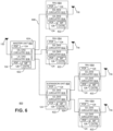
- the downlink DAS circuitry 610 in each master unit 602 is also configured to generate one or more downlink transport signals derived from one or more base station downlink signals and to transmit one or more downlink transport signals to one or more of the remote antenna units 604.
- Each master unit 602 comprises uplink DAS circuitry 616 that is configured to receive the respective uplink transport signals transmitted to it from one or more remote antenna units 604 and to use the received uplink transport signals to generate one or more base station uplink radio frequency signals that are provided to the one or more base stations 102 associated with that master unit 602. Typically, this involves, among other things, combining or summing uplink signals received from multiple remote antenna units 604 in order to produce the base station signal provided to each base station 102. In this way, the DAS 600 increases the coverage area for the uplink capacity provided by the base stations 102.
- one or more remote antenna units 604 are coupled to one or more master units 602 via one or more other remote antenna units 604 (for examples, where the remote antenna units 604 are coupled together in a daisy chain or ring topology).
- the downlink DAS circuitry 610, 612, and 618 and uplink DAS circuitry 614, 616, and 620 in each master unit 602, remote antenna unit 604, and expansion unit 608, respectively, can comprise one or more appropriate connectors, attenuators, combiners, splitters, amplifiers, filters, duplexers, analog-to-digital converters, digital-to-analog converters, electrical-to-optical converters, optical-to-electrical converters, mixers, field-programmable gate arrays (FPGAs), microprocessors, transceivers, framers, etc., to implement the features described above. Also, the downlink DAS circuitry 610, 612, and 618 and uplink DAS circuitry 614, 616, and 620 may share common circuitry and/or components.
- the DAS 600 can use either digital transport, analog transport, or combinations of digital and analog transport for generating and communicating the transport signals between the master units 602, the remote antenna units 604, and any expansion units 608.
- each master unit 602 and expansion unit 608 includes a simulcast/combining function 624 that simulcasts (that is, splits or makes copies of) the downlink signals to multiple remote antenna units 604 and combines or sums uplink signals received from multiple remote antenna units 604.
- Example 9 includes the repeater system of Example 8, wherein the base station is shared with the repeater system and the base station antenna system co-located with the base station using at least one of: an RF splitter and combiner; and a donor antenna.
- Example 12 includes the repeater system of Example 11, wherein the uplink random access channel procedure comprises a Long Term Evolution (LTE) random access channel procedure performed using the physical random access channel (PRACH).
- LTE Long Term Evolution
- PRACH physical random access channel
- Example 14 includes the repeater system of any of the Examples 1-13, wherein the first threshold value and the second threshold value are one of: different values and the same value.
- Example 15 includes the repeater system of any of the Examples 1-14, wherein the first threshold value differs from the second threshold value in order to account for hysteresis.
- Example 18 includes the method of any of the Examples 16-17, wherein the repeater system comprises a single-node repeater.
- Example 39 includes the method of Example 38, wherein the confirmation mechanism to confirm that the repeater circuitry should be operated in the unmuted state causes the repeater circuitry to be operated in the unmuted state if a first predetermined period elapses without the received power level ever crossing the second threshold value; and wherein the confirmation mechanism to confirm that the repeater circuitry should be operated in the muted state causes the repeater circuitry to be operated in the muted state if a second predetermined period elapses without the received power level ever crossing first threshold value.
Landscapes
- Engineering & Computer Science (AREA)
- Computer Networks & Wireless Communication (AREA)
- Signal Processing (AREA)
- Mobile Radio Communication Systems (AREA)
- Radio Relay Systems (AREA)
Applications Claiming Priority (3)
| Application Number | Priority Date | Filing Date | Title |
|---|---|---|---|
| US201762482747P | 2017-04-07 | 2017-04-07 | |
| PCT/US2018/026602 WO2018187778A1 (fr) | 2017-04-07 | 2018-04-06 | Blocage automatique de sortie pour systèmes répéteurs actifs |
| EP18781079.1A EP3607672B1 (fr) | 2017-04-07 | 2018-04-06 | Blocage automatique de sortie pour systèmes répéteurs actifs |
Related Parent Applications (1)
| Application Number | Title | Priority Date | Filing Date |
|---|---|---|---|
| EP18781079.1A Division EP3607672B1 (fr) | 2017-04-07 | 2018-04-06 | Blocage automatique de sortie pour systèmes répéteurs actifs |
Publications (2)
| Publication Number | Publication Date |
|---|---|
| EP4236107A2 true EP4236107A2 (fr) | 2023-08-30 |
| EP4236107A3 EP4236107A3 (fr) | 2023-10-18 |
Family
ID=63711881
Family Applications (2)
| Application Number | Title | Priority Date | Filing Date |
|---|---|---|---|
| EP23180228.1A Pending EP4236107A3 (fr) | 2017-04-07 | 2018-04-06 | Blocage automatique de sortie pour systèmes répéteurs actifs |
| EP18781079.1A Active EP3607672B1 (fr) | 2017-04-07 | 2018-04-06 | Blocage automatique de sortie pour systèmes répéteurs actifs |
Family Applications After (1)
| Application Number | Title | Priority Date | Filing Date |
|---|---|---|---|
| EP18781079.1A Active EP3607672B1 (fr) | 2017-04-07 | 2018-04-06 | Blocage automatique de sortie pour systèmes répéteurs actifs |
Country Status (3)
| Country | Link |
|---|---|
| US (1) | US10742305B2 (fr) |
| EP (2) | EP4236107A3 (fr) |
| WO (1) | WO2018187778A1 (fr) |
Families Citing this family (8)
| Publication number | Priority date | Publication date | Assignee | Title |
|---|---|---|---|---|
| EP3556027B1 (fr) * | 2016-12-16 | 2022-10-05 | Commscope Technologies LLC | Procédé et appareil de fonctionnement d'émetteurs-récepteurs colocalisés sur la même bande de fréquences |
| US20200221503A1 (en) * | 2017-09-28 | 2020-07-09 | Sony Corporation | Terminal device, base station device, method, and recording medium |
| US11178726B2 (en) | 2018-10-19 | 2021-11-16 | Qualcomm Incorporated | User equipment cooperative multipoint reception and transmission |
| WO2020117835A1 (fr) * | 2018-12-04 | 2020-06-11 | Commscope Technologies Llc | Système d'antenne distribué destiné à être utilisé le long d'une voie de train |
| US11722207B2 (en) * | 2019-08-06 | 2023-08-08 | Commscope Technologies Llc | Repeater system using umbrella base station |
| JP7630242B2 (ja) * | 2020-07-13 | 2025-02-17 | 株式会社東芝 | 通信中継装置およびコンピュータプログラム |
| EP4278478A4 (fr) * | 2021-01-13 | 2024-11-27 | Outdoor Wireless Networks LLC | Système répéteur destiné à être utilisé avec une station de base de nouvelle radio 5g |
| EP4391413A1 (fr) * | 2022-12-23 | 2024-06-26 | Nokia Solutions and Networks Oy | Appareil, procédé, programme informatique pour la répétition de signaux |
Family Cites Families (10)
| Publication number | Priority date | Publication date | Assignee | Title |
|---|---|---|---|---|
| WO1994026036A1 (fr) * | 1993-05-04 | 1994-11-10 | Motorola Inc. | Appareil et procede permettant d'eliminer le bruit dans un signal de sortie audible |
| US6748194B2 (en) * | 2001-02-28 | 2004-06-08 | Korea Telecom M.Com Co., Ltd. | Repeater system having oscillation preventing function and automatic reverse output disabling function for non-subscriber and control method thereof |
| KR100896207B1 (ko) * | 2006-01-24 | 2009-05-12 | 삼성전자주식회사 | 다중 홉 릴레이 방식의 광대역 무선 통신시스템에서중계국의 중계 모드를 선택하기 위한 장치 및 방법 |
| GB0624218D0 (en) * | 2006-12-04 | 2007-01-10 | Vodafone Plc | Base station repeater |
| JP5712934B2 (ja) * | 2009-12-24 | 2015-05-07 | 日本電気株式会社 | 中継装置、中継システム、中継方法、無線通信システム、プログラム |
| KR101710607B1 (ko) * | 2010-01-20 | 2017-02-27 | 삼성전자주식회사 | 이동통신 시스템에서 단말기의 핸드오버를 지원하는 방법 및 장치 |
| US8260197B2 (en) | 2010-02-11 | 2012-09-04 | Kabushiki Kaisha Kenwood | Radio repeating system, radio repeating apparatus, radio terminal operating method and radio repeating method |
| CA2838740A1 (fr) * | 2011-06-13 | 2012-12-20 | Adc Telecommunications, Inc. | Architectures de systeme d'antenne distribue |
| EP3036852B1 (fr) | 2013-08-21 | 2022-05-11 | Aviat Networks, Inc. | Systèmes et procédés pour des répéteurs adaptatifs |
| EP3823185B1 (fr) * | 2014-04-08 | 2025-09-24 | Outdoor Wireless Networks LLC | Système de répéteur numérique |
-
2018
- 2018-04-06 EP EP23180228.1A patent/EP4236107A3/fr active Pending
- 2018-04-06 EP EP18781079.1A patent/EP3607672B1/fr active Active
- 2018-04-06 US US15/947,685 patent/US10742305B2/en active Active
- 2018-04-06 WO PCT/US2018/026602 patent/WO2018187778A1/fr not_active Ceased
Also Published As
| Publication number | Publication date |
|---|---|
| WO2018187778A1 (fr) | 2018-10-11 |
| US20180294867A1 (en) | 2018-10-11 |
| EP3607672A1 (fr) | 2020-02-12 |
| EP3607672B1 (fr) | 2023-06-21 |
| EP3607672A4 (fr) | 2020-12-16 |
| US10742305B2 (en) | 2020-08-11 |
| EP4236107A3 (fr) | 2023-10-18 |
Similar Documents
| Publication | Publication Date | Title |
|---|---|---|
| US10742305B2 (en) | Output muting are active repeater systems | |
| US11784735B2 (en) | Booster gain adjustment based on user equipment (UE) need | |
| US11637621B2 (en) | Repeater system for use with 5G new radio base station that uses time-division duplexing | |
| EP3363125B1 (fr) | Découpage en canaux pour amplificateurs de signaux | |
| EP2375571B1 (fr) | Appareil d'équipement d'utilisateur pour la transmission simultanée de signaux via plusieurs puces de communication sans fil sur lesquelles différents schémas de communication sans fil sont appliqués et procédé de contrôle de la puissance de transmission | |
| EP3345440B1 (fr) | Systèmes et procédés pour déterminer la position d'un équipement d'utilisateur dans un système d'antennes distribuées sans fil | |
| JPWO2011077862A1 (ja) | 中継装置、中継システム、中継方法、無線通信システム、プログラム | |
| US11563549B2 (en) | Selectable band suppression for a distributed antenna system | |
| WO2020048277A1 (fr) | Circuit radiofréquence et dispositif de communication | |
| KR20170044975A (ko) | 긴급 재난 통신 시스템 | |
| JP2010004515A (ja) | 中継送受信装置、および、移動体通信システム | |
| US20220224400A1 (en) | Repeater system for use with 5g new radio base station | |
| JP3742372B2 (ja) | 逆方向リンクの干渉を抑制する建物内の無線通信システム及びその方法 | |
| CN119865827B (zh) | 室内分布系统 | |
| US20240205842A1 (en) | System for controlling the emissions of a repeater | |
| KR20250046992A (ko) | 통신 인프라 공유를 위한 이득 균일도 자가 보정 방법 | |
| KR20180016138A (ko) | 통합공공망용 무선신호 중계장치 및 그 제어방법 | |
| KR20180005495A (ko) | 시분할 듀플렉스 방식의 rf 중계장치 | |
| KR101157136B1 (ko) | 다중 경로 중계기 장치 및 다중 경로 중계기 장치의 제어방법 | |
| KR101791635B1 (ko) | 주파수별 이득 제어가 가능한 멀티밴드 중계기 | |
| KR101486855B1 (ko) | 이동통신 신호의 출력 레벨 제어 방법 및 장치 | |
| KR20150105734A (ko) | 통신 단말 장치와 그 핸드오버 방법 | |
| KR20160080827A (ko) | 디지털 입력 오버플로우 처리 장치 |
Legal Events
| Date | Code | Title | Description |
|---|---|---|---|
| PUAI | Public reference made under article 153(3) epc to a published international application that has entered the european phase |
Free format text: ORIGINAL CODE: 0009012 |
|
| STAA | Information on the status of an ep patent application or granted ep patent |
Free format text: STATUS: REQUEST FOR EXAMINATION WAS MADE |
|
| 17P | Request for examination filed |
Effective date: 20230620 |
|
| AC | Divisional application: reference to earlier application |
Ref document number: 3607672 Country of ref document: EP Kind code of ref document: P |
|
| AK | Designated contracting states |
Kind code of ref document: A2 Designated state(s): AL AT BE BG CH CY CZ DE DK EE ES FI FR GB GR HR HU IE IS IT LI LT LU LV MC MK MT NL NO PL PT RO RS SE SI SK SM TR |
|
| PUAL | Search report despatched |
Free format text: ORIGINAL CODE: 0009013 |
|
| AK | Designated contracting states |
Kind code of ref document: A3 Designated state(s): AL AT BE BG CH CY CZ DE DK EE ES FI FR GB GR HR HU IE IS IT LI LT LU LV MC MK MT NL NO PL PT RO RS SE SI SK SM TR |
|
| RIC1 | Information provided on ipc code assigned before grant |
Ipc: H04B 7/155 20060101AFI20230911BHEP |
|
| RAP3 | Party data changed (applicant data changed or rights of an application transferred) |
Owner name: COMMSCOPE TECHNOLOGIES LLC |
|
| RAP1 | Party data changed (applicant data changed or rights of an application transferred) |
Owner name: OUTDOOR WIRELESS NETWORKS LLC |
|
| STAA | Information on the status of an ep patent application or granted ep patent |
Free format text: STATUS: EXAMINATION IS IN PROGRESS |
|
| 17Q | First examination report despatched |
Effective date: 20250717 |