EP4236178A2 - Downlink control information (dci) size matching - Google Patents
Downlink control information (dci) size matching Download PDFInfo
- Publication number
- EP4236178A2 EP4236178A2 EP23179258.1A EP23179258A EP4236178A2 EP 4236178 A2 EP4236178 A2 EP 4236178A2 EP 23179258 A EP23179258 A EP 23179258A EP 4236178 A2 EP4236178 A2 EP 4236178A2
- Authority
- EP
- European Patent Office
- Prior art keywords
- dci format
- size
- uss
- monitored
- dci
- Prior art date
- Legal status (The legal status is an assumption and is not a legal conclusion. Google has not performed a legal analysis and makes no representation as to the accuracy of the status listed.)
- Granted
Links
Images

Classifications
-
- H—ELECTRICITY
- H04—ELECTRIC COMMUNICATION TECHNIQUE
- H04W—WIRELESS COMMUNICATION NETWORKS
- H04W72/00—Local resource management
- H04W72/50—Allocation or scheduling criteria for wireless resources
- H04W72/53—Allocation or scheduling criteria for wireless resources based on regulatory allocation policies
-
- H—ELECTRICITY
- H04—ELECTRIC COMMUNICATION TECHNIQUE
- H04W—WIRELESS COMMUNICATION NETWORKS
- H04W72/00—Local resource management
- H04W72/20—Control channels or signalling for resource management
- H04W72/23—Control channels or signalling for resource management in the downlink direction of a wireless link, i.e. towards a terminal
- H04W72/232—Control channels or signalling for resource management in the downlink direction of a wireless link, i.e. towards a terminal the control data signalling from the physical layer, e.g. DCI signalling
-
- H—ELECTRICITY
- H04—ELECTRIC COMMUNICATION TECHNIQUE
- H04L—TRANSMISSION OF DIGITAL INFORMATION, e.g. TELEGRAPHIC COMMUNICATION
- H04L5/00—Arrangements affording multiple use of the transmission path
- H04L5/003—Arrangements for allocating sub-channels of the transmission path
- H04L5/0053—Allocation of signalling, i.e. of overhead other than pilot signals
-
- H—ELECTRICITY
- H04—ELECTRIC COMMUNICATION TECHNIQUE
- H04W—WIRELESS COMMUNICATION NETWORKS
- H04W24/00—Supervisory, monitoring or testing arrangements
- H04W24/08—Testing, supervising or monitoring using real traffic
-
- H—ELECTRICITY
- H04—ELECTRIC COMMUNICATION TECHNIQUE
- H04W—WIRELESS COMMUNICATION NETWORKS
- H04W72/00—Local resource management
- H04W72/04—Wireless resource allocation
- H04W72/044—Wireless resource allocation based on the type of the allocated resource
- H04W72/0453—Resources in frequency domain, e.g. a carrier in FDMA
-
- H—ELECTRICITY
- H04—ELECTRIC COMMUNICATION TECHNIQUE
- H04W—WIRELESS COMMUNICATION NETWORKS
- H04W72/00—Local resource management
- H04W72/04—Wireless resource allocation
- H04W72/044—Wireless resource allocation based on the type of the allocated resource
- H04W72/0457—Variable allocation of band or rate
-
- H—ELECTRICITY
- H04—ELECTRIC COMMUNICATION TECHNIQUE
- H04W—WIRELESS COMMUNICATION NETWORKS
- H04W72/00—Local resource management
- H04W72/20—Control channels or signalling for resource management
- H04W72/23—Control channels or signalling for resource management in the downlink direction of a wireless link, i.e. towards a terminal
Definitions
- the 5th generation (5G) wireless access technology currently under development by members of the 3 rd -Generation Partnership Project (3GPP), known as new radio (NR), will address a variety of usage scenarios from enhanced mobile broadband (eMBB) to ultra-reliable low-latency communications (URLLC) to massive machine-type communications (mMTC).
- eMBB enhanced mobile broadband
- URLLC ultra-reliable low-latency communications
- mMTC massive machine-type communications
- Key NR features include ultra-lean transmission, support for low latency, advanced antenna technologies, and spectrum flexibility including operation in high frequency bands, interworking between high and low frequency bands, and dynamic time division multiplexing (TDD).
- TDD dynamic time division multiplexing
- Downlink control information is used in NR to, among other things, transmit scheduling decisions from the gNB (3GPP terminology for an NR base station) to the UE (3GPP terminology for an access terminal, such as a mobile telephone or a machine-type communications (MTC) device.
- DCI formats are defined for different purposes, differing in, for example, the information carried in the DCI.
- a UE blindly detects the DCI format based on (among other things) payload size and the RNTI used.
- DCI size budget is a major constraint in NR specification to respect UE processing capability. This constraint is captured in 3GPP TS 38.212 as follows:
- the DCI formats supported in NR include:
- the DCI formats 0_0 and 1_0 are usually referred to as fallback DCI.
- the DCI formats 0_1 and 1_1 are usually referred to as non-fallback DCI.
- the UE blindly attempts to decode DCI messages using the RNTIs the UE is supposed to monitor. If the CRC checks, the DCI is correctly received and intended for this UE, and the UE thus follows the content of the DCI. If the CRC does not check, either the DCI was received in error or it was intended for another UE - in either case, the UE ignores it. Blindly detecting the DCI is done according to search spaces that can be configured in the UE. Search spaces can be either common search spaces (CSS) or UE-specific search spaces (USS). Not all RNTIs or DCI formats are allowed in all search spaces:
- RNTI Radio Network Temporary Identifier
- CRC Cyclic Redundancy Check
- NR DCI can be found in Section 7.3.1 of 3GPP TS 38.212, v15.3.0.
- a UE may be active on a wide bandwidth for a short time, e.g., in the event of bursty traffic, while being active on a narrow bandwidth for the remaining time.
- bandwidth adaptation is addressed in NR by a new concept known as bandwidth part (BWP).
- a BWP is a subset of contiguous RBs on the carrier. Up to four bandwidth parts can be configured in the UE for each of the UL and DL, but at a given time only one bandwidth part is active per transmission direction.
- the UE can receive on a narrow BWP and, when needed, the network can dynamically inform the UE to switch to a wider BWP for reception.
- DCI downlink control information
- the present disclosure provides several systematic DCI size matching procedures that provide exact instructions on how DCI size matching is to be performed. With these procedures, consistent and exact DCI size matching can be performed, ensuring common understanding of DCI contents between the UE and the network.
- Embodiments of techniques disclosed herein include methods, implemented by a UE, for determining DCI sizes for monitoring by the UE.
- the method comprises determining DCI sizes for monitoring by performing size matching between different DCI formats according to a "Rule 1" as described herein and according to any one or more of "Rule 2" through “Rule 9,” as described herein.
- Rule 1 specifies that for a frequency domain resource allocation (FDRA) field in each DCI, the UE should use a field size that is a function of the size of a bandwidth part (BWP) wherein the size of the bandwidth part in the function is determined according to a first rule specifying that (i) the size of the BWP is the size of an active uplink BWP or an initial uplink BWP for a DCI format 0_0 monitored in a UE-specific search space (USS), (ii) the size of the BWP is the size of an initial uplink BWP for a DCI format 0_0 not monitored in a USS, (iii) the size of the BWP is the size of an active downlink BWP or an initial downlink BWP or CORESET 0 for a DCI format 1_0 monitored in a USS, (iv) the size of the BWP is the size of an initial downlink BWP for DCI format 1_0 not monitored in a USS,
- Corresponding techniques disclosed herein include methods, implemented by a base station, for determining DCI sizes for monitoring by a UE served by the base station.
- the method likewise comprises determining DCI sizes for monitoring by performing size matching between different DCI formats according to the "Rule 1" described herein and according to any one or more of "Rule 2" through “Rule 9,” as described herein.
- each rule provides definitions and/or procedures to be followed for determining DCI sizes, while remaining within the predetermined DCI size budget mentioned above.
- the rules described below may be implemented by a UE, for determining DCI sizes when performing blind decoding and demodulation of DCI messages, as well as by a base station, e.g., a gNB, when assembling and transmitting DCI messages to one or more UEs.
- a base station e.g., a gNB
- the use of these rules in a consistent manner ensures that the UEs and the gNBs have a common understanding of the DCI formats, contents, and structure.
- Each of several of the rules below are targeted to specific configurations, e.g., with respect to whether fallback DCI formats are configured for a common search space (CSS) or UE-specific search space (USS).
- CCS common search space
- USS UE-specific search space
- various embodiments and implementations of the presently disclosed techniques may incorporate one, several, or all of these rules.
- alternative versions of the rule are presented - a given embodiment may implement one of these alternatives.
- some embodiments may implement each of the rules below, implementing a single alternative for those rules that are presented with several alternatives. It should be understood, however, that a given embodiment might not implement all of the rules below.
- a different rule may be substituted for one or more of the below, e.g., for a particular configuration.
- Rule 0 specifies a DCI budget size constraint, which the other rules seek to maintain.
- Rule 1 does not specify a complete rule for DCI sizing, but defines parameters that are used to determine a field size in the DCI, which field size influences the DCI size in each of the subsequent rules.
- Rule 1 combine rule 1 with any or all of the subsequent Rules 2-9.
- An example of a combined rule, according to some embodiments, is also provided below.
- the "3+1" DCI budget is extended as follows:
- the size of FDRA (Frequency Domain Resource Assignment) field is a function of the size of the active UL BWP, if DCI 0_0 is monitored in USS and provided that the size budget (in terms of the number of DCI sizes that must be monitored) is satisfied; otherwise the size of FDRA field is given by the initial UL BWP.
- the size of FDRA field is a function of the size of the DL BWP, if DCI 1_0 is monitored in USS and provided that the size budget is satisfied; otherwise the size of FDRA field is given by the CORESET#0 if CORESET#0 is present and given by the initial DL BWP if CORESET#0 is not present.
- Non-fallback DCI 0_1 may be scrambled with C-RNTI or CS-RNTI or SP-CSI-RNTI or MCS-C-RNTI, and may be used to schedule SUL and non-SUL.
- Non-fallback DCI 1_1 may be scrambled with C-RNTI or CS-RNTI or MCS-C-RNTI. It is necessary to align the size of each smaller DCI 0_1 to the maximum size of DCI 0_1; likewise, the size of each smaller DC 1_1 must be aligned to the maximum size of DCI 1_1.
- USS DCI 0_0 size and USS 1_0 size should be matched, which would guarantee the size budget is met.
- Two different approaches are detailed below, in rules 3-a and 3-b. Note that as discussed in the background section above, when both fallback DCI and non-fallback DCI are configured in USS, as may be the case for both Rule 3-a and Rule 3-b, they are necessarily in different USSs.
- DCI size budget (the "3" part) is satisfied, and no size matching for non-fallback DCI. Note that adding 1 bit to non-fallback DCI applies only if non-fallback DCI happens to be the same size as USS fallback DCI, which is not present under this case.
- DCI size matching can be performed according to rule 7-c or 7-d using the rule 7-a or 7-b as a building block.
- Rule 7-a description for method 1 (as a building block for rule 7-c/7-cc/7-d)
- Rule 7-b description for method 2 (as a building block for rule 7-c/7-cc/7-d)
- rule 7-c or 7-cc The above procedure is complicated. A simplified approach would be regardless of whether DCI size budget (before padding) is satisfied or not, simply carry out the following procedure per rule 7-d:
- DCI 2-2 or DCI 2-3 are configured, it is good to align their sizes to DCI 1_0/0_0 in CSS if DCI budget is not satisfied.
- Rules 1 to 9 can be applied accordingly.
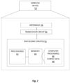
- FIG. 1 illustrates a diagram of an example of a user equipment (UE), illustrated as a wireless device 50, according to some embodiments.
- the wireless device 50 can be any type of wireless device capable of communicating with a network node or another wireless device (e.g., UE) over radio signals.
- the wireless device 50 may also be radio communication device, target device, device to device (D2D) UE, V2X UE, ProSe UE, machine type UE or UE capable of machine to machine communication (M2M), a sensor equipped with UE, PDA (personal digital assistant), iPAD, Tablet, mobile terminals, smart phone, laptop embedded equipment (LEE), laptop mounted equipment (LME), USB dongles, Customer Premises Equipment (CPE), etc.
- D2D device to device
- V2X UE V2X UE
- ProSe UE machine type UE or UE capable of machine to machine communication
- M2M machine to machine communication
- PDA personal digital assistant
- iPAD Tablet
- the wireless device 50 communicates with a radio node or base station via antennas 54 and a transceiver circuit 56.
- the transceiver circuit 56 may include transmitter circuits, receiver circuits, and associated control circuits that are collectively configured to transmit and receive signals according to a radio access technology, for the purposes of providing cellular communication services.
- the wireless device 50 also includes one or more processing circuits 52 that are operatively associated with the radio transceiver circuit 56.
- the processing circuitry 52 comprises one or more digital processing circuits 62, e.g., one or more microprocessors, microcontrollers, Digital Signal Processors (DSPs), Field Programmable Gate Arrays (FPGAs), Complex Programmable Logic Devices (CPLDs), Application Specific Integrated Circuits (ASICs), or any mix thereof. More generally, the processing circuitry 52 may comprise fixed circuitry, or programmable circuitry that is specially adapted via the execution of program instructions implementing the functionality taught herein, or may comprise some mix of fixed and programmed circuitry.
- the processing circuitry 52 may be multi-core.
- the processing circuitry 52 also includes a memory 64.
- the memory 64 stores one or more computer programs 66 and, optionally, configuration data 68.
- the memory 64 provides non-transitory storage for the computer program 66 and it may comprise one or more types of computer-readable media, such as disk storage, solid-state memory storage, or any mix thereof.
- the memory 64 comprises any one or more of SRAM, DRAM, EEPROM, and FLASH memory, which may be in the processing circuitry 52 and/or separate from the processing circuitry 52.
- the memory 64 comprises one or more types of computer-readable storage media providing non-transitory storage of the computer program 66 and any configuration data 68 used by the wireless device 50.
- “non-transitory” means permanent, semi-permanent, or at least temporarily persistent storage and encompasses both long-term storage in non-volatile memory and storage in working memory, e.g., for program execution.
- the wireless device 50 may be configured to perform all or some of the techniques described above.
- the processor 62 of the processor circuitry 52 may execute a computer program 66 stored in the memory 64 that configures the processor 62 to determine DCI sizes for monitoring by the wireless device, by performing size matching between different DCI formats according to rule 1 as described herein and according to any one or more of rules 2-9 as described herein.
- Figure 2 illustrates a diagram of a network node 30, such as a base station, that can determine DCI sizes to be monitored by the wireless device 50 and other devices, according to some embodiments.
- the network node 30 facilitates communication between wireless devices and the core network.
- Network node is a more general term and can correspond to any type of radio network node or any network node, which communicates with a UE and/or with another network node. Examples of network nodes are NodeB, base station (BS), multi-standard radio (MSR) radio node such as MSR BS, eNodeB, gNodeB.
- MSR multi-standard radio
- MeNB SeNB
- network controller radio network controller (RNC), base station controller (BSC), road side unit (RSU), relay, donor node controlling relay, base transceiver station (BTS), access point (AP), transmission points, transmission nodes, RRU, RRH, nodes in distributed antenna system (DAS), core network node (e.g. MSC, MME, etc), O&M, OSS, SON, positioning node (e.g. E-SMLC) etc.
- RNC radio network controller
- BSC base station controller
- RSU road side unit
- BTS base transceiver station
- AP access point
- transmission points transmission nodes
- RRU RRU
- RRH nodes in distributed antenna system
- nodes in distributed antenna system DAS
- core network node e.g. MSC, MME, etc
- O&M core network node
- OSS e.g. MSC, MME, etc
- SON positioning node
- the network node 30 includes communication interface circuitry 38 that includes circuitry for communicating with other nodes in the core network, radio nodes, and/or other types of nodes in the network for the purposes of providing data and cellular communication services.
- the network node 30 communicates with wireless devices via antennas 34 and transceiver circuitry 36.
- the transceiver circuitry 36 may include transmitter circuits, receiver circuits, and associated control circuits that are collectively configured to transmit and receive signals according to a radio access technology, for the purposes of providing cellular communication services.
- the network node 30 also includes one or more processing circuits 32 that are operatively associated with the communication interface circuitry 38 and/or the transceiver circuitry 36.
- the network node 30 uses the communication interface circuitry 38 to communicate with network nodes and the transceiver circuitry 36 to communicate with user equipments.
- the one or more processing circuits 32 are referred to hereafter as "the processing circuitry 32.”
- the processing circuitry 32 comprises one or more digital processors 42, e.g., one or more microprocessors, microcontrollers, DSPs, FPGAs, CPLDs, ASICs, or any mix thereof.
- the processing circuitry 32 may comprise fixed circuitry, or programmable circuitry that is specially configured via the execution of program instructions implementing the functionality taught herein, or may comprise some mix of fixed and programmed circuitry.
- the processor 42 may be multi-core, i.e., having two or more processor cores utilized for enhanced performance, reduced power consumption, and more efficient simultaneous processing of multiple tasks.
- the processing circuitry 32 also includes a memory 44.
- the memory 44 stores one or more computer programs 46 and, optionally, configuration data 48.
- the memory 44 provides non-transitory storage for the computer program 46 and it may comprise one or more types of computer-readable media, such as disk storage, solid-state memory storage, or any mix thereof.
- the memory 44 comprises any one or more of SRAM, DRAM, EEPROM, and FLASH memory, which may be in the processing circuitry 32 and/or separate from the processing circuitry 32.
- the memory 44 comprises one or more types of computer-readable storage media providing non-transitory storage of the computer program 46 and any configuration data 48 used by the network node 30.
- the processing circuitry 32 is also configured, in some embodiments, to determine DCI sizes to be monitored by the UE by performing size matching between different DCI formats according to rule 1 as described herein and according to any one or more of rules 2-9 as described herein.
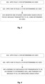
- Figure 3 illustrates a process flow diagram for an example method according to some of the techniques described herein.
- the method illustrated in Figure 3 includes the application by a UE of Rule 1, as described above, and optionally includes the application of any one or more of Rules 2-9, as well.
- the UE applies Rule 1.
- the UE uses a field size that is a function of the size of a bandwidth part (BWP), wherein the size of the bandwidth part in the function is determined according to a first rule specifying that (i) the size of the BWP is the size of an active uplink BWP or an initial uplink BWP for a DCI format 0_0 monitored in a UE-specific search space (USS), (ii) the size of the BWP is the size of an initial uplink BWP for a DCI format 0_0 not monitored in a USS, (iii) the size of the BWP is the size of an active downlink BWP or an initial downlink BWP or CORESET 0 for a DCI format 1_0 monitored in a USS, (iv) the size of the BWP is the size of an initial downlink BWP for DCI
- FDRA frequency domain resource allocation
- the UE applies any one or more of Rules 2-9, as described above.
- This may comprise, for example, for each DCI format 0_1 and 1_1 monitored in a USS, applying a second rule specifying that (i) zero padding is added to a DCI format 0_1 smaller than a maximum size of DCI format 0_1, until the size of the DCI format 0_1 is equal to the maximum size of DCI format 0_1, and (ii) zero padding is added to a DCI format 1_1 smaller than a maximum size of DCI format 1_1, until the size of the DCI format 1_1 is equal to the maximum size of DCI format 1_1.
- this may comprise, for each DCI format 0_0 and DCI format 1_0 monitored in a first USS, applying a third rule specifying that (i) if the size of the DCI format 0_0 is smaller than the size of a DCI format 1_0 configured to be monitored by the UE in the first USS, zeroes are added to the DCI format 0_0 until the size of the DCI format 0_0 equals the size of DCI format 1_0 configured to be monitored by the UE in the first USS, (ii) if the size of the DCI format 1_0 is smaller than the size of a DCI format 0_0 configured to be monitored by the UE in the first USS, zeroes are added to the DCI format 1_0 until the size of the DCI format 1_0 equals the size of the DCI format 0_0 configured to be monitored by the UE in the first USS, (iii) if the size of any DCI format 0_1 monitored in a USS
- this may comprise, for each DCI format 0_0 and DCI format DCI 1_0 monitored in a common search space (CSS), applying a fourth rule specifying that (i) if the size of the DCI format 0_0 monitored in the CSS is less than the size of a DCI format 1_0 monitored in the CSS, zeroes are added to the DCI format 0_0 monitored in the CSS until the size of the DCI format 0_0 monitored in the CSS is equal to the size of the DCI format 1_0 monitored in the CSS, and (ii) if the size of the DCI format 1_0 monitored in the CSS is less than the size of a DCI format 0_0 monitored in the CSS, most significant bits of the FDRA field in the DCI format 0_0 are truncated until the size of the DCI format 0_0 monitored in the CSS is equal to the size of the DCI format 1_0 monitored in the CSS.
- a common search space CSS
- this may further comprise, after applying the fourth rule, applying a fifth rule specifying that, for each DCI format 0_0 monitored in a USS, if the size of the DCI format 0_0 monitored in the USS is less than the size of a DCI format 1_0 monitored in the USS, zeroes are added to the DCI format 0_0 monitored in the USS until the size of the DCI format 0_0 monitored in the USS is equal to the size of the DCI format 1_0 monitored in the USS; and for each DCI format 1_0 monitored in a USS, if the size of the DCI format 1_0 monitored in the USS is less than the size of a DCI format 0_0 monitored in the USS, zeroes are added to the DCI format 1_0 monitored in the USS until the size of the DCI format 1_0 monitored in the USS is equal to the size of the DCI format 0_0 monitored in the USS.
- the method may comprise, responsive to (i) DCI format 0_0 or DCI format 1_0 being configured for monitoring by the UE in a common search space (CSS), and (ii) DCI format 0_0 or DCI format 1_0 being configured for monitoring by the UE in a first USS, and (iii) DCI format 0_1 or DCI format 1_1 being configured for monitoring by the UE in a second USS, applying a sixth rule specifying that: for each DCI format 0_0 monitored in the CSS, the field size for the FDRA field is determined as a function of the initial uplink BWP; for each DCI format 1_0 monitored in the CSS, the field size for the FDRA field is determined as a function of the size of CORESET 0, if CORESET 0 is present, or as a function of the size of the initial downlink BWP, if CORESET 0 is not present; for each DCI format 0_0 monitored in the first USS, if
- the method may comprise, after applying the fourth rule, applying a seventh rule according to Rule 7cc described above.
- the method may comprise, responsive to both DCI format 2_0 and DCI format 2_1 being configured for monitoring, applying an eighth rule specifying that: for each DCI format 2_0, if a size budget limiting a number of DCI sizes the UE can be configured to monitor would otherwise be exceeded and if the size of the DCI format 2_0 is less than the size of the DCI format 2_1, zeroes are added to the DCI format 2_0 until the size of the DCI format 2_0 is equal to the size of the DCI format 2_1; and for each DCI format 2_1, if a size budget limiting a number of DCI sizes the UE can be configured to monitor would otherwise be exceeded and if the size of the DCI format 2_1 is less than the size of the DCI format 2_0, zeroes are added to the DCI format 2_1 until the size of the DCI format 2_1 is equal to the size of the DCI format 2_0.
- the method shown in Figure 3 may comprise, responsive to either DCI format 2_2 or DCI format 2_3 being configured for monitoring by the UE, applying a ninth rule specifying that: for each DCI format 2_2, if a size budget limiting a number of DCI sizes the UE can be configured to monitor would otherwise be exceeded and if the size of the DCI format 2_2 is less than the size of the DCI format 1_0 monitored in the CSS, zeroes are added to the DCI format 2_2 until the size of the DCI format 2_2 is equal to the size of the DCI format 1_0 monitored in the CSS; for each DCI format 2_3, if a size budget limiting a number of DCI sizes the UE can be configured to monitor would otherwise be exceeded and if the size of the DCI format 2_3 is less than the size of the DCI format 1_0 monitored in the CSS, zeroes are added to the DCI format 2_3 until the size of the DCI format 2_3 is equal to the size of the DCI
- the method carried out by the UE may further comprise monitoring one or more configured search spaces for a DCI message targeted to the user equipment, using the determined DCI sizes. This is shown at block 330 of Figure 3 .
- Figure 4 illustrates a process flow diagram for another example method according to some of the techniques described herein.
- the method illustrated in Figure 4 includes the application by a base station, such as a gNB, of Rule 1 as described above, for determining DCI sizes to be monitored by a UE, and optionally includes the application of any one or more of Rules 2-9, as well.
- a base station such as a gNB
- the base station applies Rule 1.
- the base station uses a field size that is a function of the size of a bandwidth part (BWP), where the size of the bandwidth part in the function is determined according to a first rule specifying that (i) the size of the BWP is the size of an active uplink BWP or an initial uplink BWP for a DCI format 0_0 configured to be monitored by the UE in a UE-specific search space (USS), (ii) the size of the BWP is the size of an initial uplink BWP for a DCI format 0_0 not configured to be monitored by the UE in a USS, (iii) the size of the BWP is the size of an active downlink BWP or an initial downlink BWP or CORESET 0_for a DCI format 1_0 configured to be monitored by the UE in a USS, (iv)
- the base station also applies any one or more of Rules 2-9, as described above.
- This may comprise, for example, for each DCI format 0_1 and 1_1 configured to be monitored by the UE in a USS, applying a second rule specifying that (i) zero padding is added to a DCI format 0_1 smaller than a maximum size of DCI format 0_1, until the size of the DCI format 0_1 is equal to the maximum size of DCI format 0_1, and (ii) zero padding is added to a DCI format 1_1 smaller than a maximum size of DCI format 1_1, until the size of the DCI format 1_1 is equal to the maximum size of DCI format 1_1.
- this may comprise, for each DCI format 0_0 and DCI format 1_0 configured to be monitored by the UE in a first USS, applying a third rule specifying that (i) if the size of the DCI format 0_0 is smaller than the size of a DCI format 1_0 configured to be monitored by the UE by the UE in the first USS, zeroes are added to the DCI format 0_0 until the size of the DCI format 0_0 equals the size of the DCI format 1_0 configured to be monitored by the UE in the first USS, (ii) if the size of the DCI format 1_0 is smaller than the size of a DCI format 0_0 configured to be monitored by the UE in the first USS, zeroes are added to the DCI format 1_0 until the size of the DCI format 1_0 equals the size of the DCI format 0_0 configured to be monitored by the UE in the first USS, (iii) if the size of any
- this may comprise, for each DCI format 0_0 and DCI format DCI 1_0 configured to be monitored by the UE in a common search space (CSS), applying a fourth rule specifying that (i) if the size of the DCI format 0_0 configured to be monitored by the UE in the CSS is less than the size of a DCI format 1_0 configured to be monitored by the UE in the CSS, zeroes are added to the DCI format 0_0 configured to be monitored by the UE in the CSS until the size of the DCI format 0_0 configured to be monitored by the UE in the CSS is equal to the size of the DCI format 1_0 configured to be monitored by the UE in the CSS, and (ii) if the size of the DCI format 1_0 configured to be monitored by the UE in the CSS is less than the size of a DCI format 0_0 configured to be monitored by the UE in the CSS, most significant bits of the FDRA field in the DCI format 0_0 configured to be
- this may further comprise, after applying the fourth rule, applying a fifth rule specifying that, for each DCI format 0_0 configured to be monitored by the UE in a USS, if the size of the DCI format 0_0 configured to be monitored by the UE in the USS is less than the size of a DCI format 1_0 configured to be monitored by the UE in the USS, zeroes are added to the DCI format 0_0 configured to be monitored by the UE in the USS until the size of the DCI format 0_0 configured to be monitored by the UE in the USS is equal to the size of the DCI format 1_0 configured to be monitored by the UE in the USS; and for each DCI format 1_0 configured to be monitored by the UE in a USS, if the size of the DCI format 1_0 configured to be monitored by the UE in the USS is less than the size of a DCI format 0_0 configured to be monitored by the UE in the USS, zeroe
- the method may comprise, responsive to (i) DCI format 0_0 or DCI format 1_0 being configured for monitoring by the UE in a common search space (CSS), and (ii) DCI format 0_0 or DCI format 1_0 being configured for monitoring by the UE in a first USS, and (iii) DCI format 0_1 or DCI format 1_1 being configured for monitoring by the UE in a second USS, applying a sixth rule specifying that: for each DCI format 0_0 configured to be monitored by the UE in the CSS, the field size for the FDRA field is determined a function of the initial uplink BWP; for each DCI format 1_0 configured to be monitored by the UE in the CSS, the field size for the FDRA field is determined as a function of the size of CORESET 0, if CORESET 0 is present, or as a function of the size of the initial downlink BWP, if CORESET 0 is not present; for each DCI format
- the method may comprise, after applying the fourth rule, applying a seventh rule according to Rule 7cc described above.
- the method may comprise, responsive to both DCI format 2_0 and DCI format 2_1 being configured for monitoring by the UE, applying an eighth rule specifying that: for each DCI format 2_0 configured to be monitored by the UE, if a size budget limiting a number of DCI sizes the UE can be configured to monitor would otherwise be exceeded and if the size of the DCI format 2_0 is less than the size of the DCI format 2_1 configured to be monitored by the UE, zeroes are added to the DCI format 2_0 until the size of the DCI format 2_0 is equal to the size of the DCI format 2_1 configured to be monitored by the UE; and for each DCI format 2_1, if a size budget limiting a number of DCI sizes the UE can be configured to monitor would otherwise be exceeded and if the size of the DCI format 2_1 is less than the size of the DCI format 2_0 configured to be monitored by the UE, zeroes are added to the DCI format 2_1 until the size
- the method shown in Figure 4 may comprise, responsive to either DCI format 2_2 or DCI format 2_3 being configured for monitoring by the UE, applying a ninth rule specifying that: for each DCI format 2_2, if a size budget limiting a number of DCI sizes the UE can be configured to monitor would otherwise be exceeded and if the size of the DCI format 2_2 is less than the size of the DCI format 1_0 configured to be monitored by the UE in the CSS, zeroes are added to the DCI format 2_2 until the size of the DCI format 2_2 is equal to the size of the DCI format 1_0 configured to be monitored by the UE in the CSS; for each DCI format 2_3, if a size budget limiting a number of DCI sizes the UE can be configured to monitor would otherwise be exceeded and if the size of the DCI format 2_3 is less than the size of the DCI format 1_0 configured to be monitored by the UE in the CSS, zeroes are added to the DCI format 2_
- the method carried out by the base station may further comprise assembling a DCI message for transmission to the UE, according to one of the determined DCI sizes, and transmitting the DCI message to the UE in a search space configured for the UE. This is shown at block 430 of Figure 4 .
- Examples of methods and apparatuses according to the present disclosure include, but are not limited to, the following:
- Example embodiment A8 The method of any of Example embodiment A1-A7, further comprising, responsive to both DCI format 2_0 and DCI format 2_1 being configured for monitoring, applying an eighth rule specifying that:
- Example embodiment A9 The method of any of Example embodiments A1-A8, further comprising, responsive to either DCI format 2_2 or DCI format 2_3 being configured for monitoring by the UE, applying a ninth rule specifying that:
- Example embodiment A10 The method of any of Example embodiment A2-A9, further comprising: monitoring one or more configured search spaces for a DCI message targeted to the user equipment, using the determined DCI sizes.
- Example embodiment A11 A method, in a base station, for determining downlink control information, DCI, sizes to be monitored by a user equipment, UE, served by the base station, the method comprising: for a frequency domain resource allocation, FDRA, field in each DCI format, using a field size that is a function of the size of a bandwidth part, BWP, wherein the size of the bandwidth part in the function is determined according to a first rule specifying that (i) the size of the BWP is the size of an active uplink BWP or an initial uplink BWP for a DCI format 0_0 configured to be monitored by the UE in a UE-specific search space, USS, (ii) the size of the BWP is the size of an initial uplink BWP for a DCI format 0_0 not configured to be monitored by the UE in a USS, (iii) the size of the BWP is the size of an active downlink BWP or an initial downlink BWP or CORESET
- Example embodiment A12 The method of Example embodiment A11, further comprising: for each DCI format 0_1 and 1_1 configured to be monitored by the UE in a USS, applying a second rule specifying that (i) zero padding is added to a DCI format 0_1 smaller than a maximum size of DCI format 0_1, until the size of the DCI format 0_1 is equal to the maximum size of DCI format 0_1, and (ii) zero padding is added to a DCI format 1_1 smaller than a maximum size of DCI format 1_1, until the size of the DCI format 1_1 is equal to the maximum size of DCI format 1_1.
- Example embodiment A13 The method of Example embodiment A11 or A12, further comprising: for each DCI format 0_0 and DCI format 1_0 configured to be monitored by the UE in a first USS, applying a third rule specifying that (i) if the size of the DCI format 0_0 is smaller than the size of a DCI format 1_0 configured to be monitored by the UE in the first USS, zeroes are added to the DCI format 0_0 until the size of the DCI format 0_0 equals the size of the DCI format 1_0 configured to be monitored by the UE in the first USS, (ii) if the size of the DCI format 1_0 is smaller than the size of a DCI format 0_0 configured to be monitored by the UE in the first USS, zeroes are added to the DCI format 1_0 until the size of the DCI format 1_0 equals the size of the DCI format 0_0 configured to be monitored by the UE in the first USS, (iii
- Example embodiment A14 The method of any of Example embodiment A11-A13, further comprising: for each DCI format 0_0 and DCI format DCI 1_0 configured to be monitored by the UE in a common search space, CSS, applying a fourth rule specifying that (i) if the size of the DCI format 0_0 configured to be monitored by the UE in the CSS is less than the size of a DCI format 1_0 configured to be monitored by the UE in the CSS, zeroes are added to the DCI format 0_0 configured to be monitored by the UE in the CSS until the size of the DCI format 0_0 configured to be monitored by the UE in the CSS is equal to the size of the DCI format 1_0 configured to be monitored by the UE in the CSS, and (ii) if the size of the DCI format 1_0 configured to be monitored by the UE in the CSS is less than the size of a DCI format 0_0 configured to be monitored by the UE in the CSS, most significant bits of the FDRA field
- Example embodiment A15 The method of claim Example embodiment A14, further comprising, after applying the fourth rule, applying a fifth rule specifying that:
- Example embodiment A16 The method of any of Example embodiment A11-A15, further comprising, responsive to (i) DCI format 0_0 or DCI format 1_0 being configured for monitoring by the UE in a common search space, CSS, and (ii) DCI format 0_0 or DCI format 1_0 being configured for monitoring by the UE in a first USS, and (iii) DCI format 0_1 or DCI format 1_1 being configured for monitoring by the UE in a second USS, applying a sixth rule specifying that:
- Example embodiment A17 The method of Example embodiment A14, further comprising, responsive to (i) DCI format 0_0 or DCI format 1_0 being configured for monitoring by the UE in a common search space, CSS, and (ii) DCI format 0_0 or DCI format 1_0 being configured for monitoring by the UE in a first USS, and (iii) DCI format 0_1 or DCI format 1_1 being configured for monitoring by the UE in a second USS, and after applying the fourth rule, applying a seventh rule specifying that:
- Example embodiment A18 The method of any of Example embodiment A11-A16, further comprising, responsive to both DCI format 2_0 and DCI format 2_1 being configured for monitoring by the UE, applying an eighth rule specifying that:
- Example embodiment A19 The method of any of claims Example embodiment A9-A14, further comprising, responsive to either DCI format 2_2 or DCI format 2_3 being configured for monitoring by the UE, applying a ninth rule specifying that:
- Example embodiment A20 The method of any of Example embodiment A12-A19, further comprising:
- Example embodiment A21 A user equipment, UE, for use in a wireless communications system, the UE being adapted to: determine DCI sizes for monitoring by performing size matching between different DCI formats according to any of claims 2-9.
- Example embodiment A22 The UE of example embodiment A21, the UE being further adapted to monitor one or more configured search spaces for a DCI message targeted to the user equipment, using the determined DCI sizes.
- Example embodiment A23 A base station, for use in a wireless communications system, the base station being adapted to: determine DCI sizes to be monitored by a user equipment, UE, by performing size matching between different DCI formats according any of Example embodiment A12-A19.
- Example embodiment A24 The base station of example embodiment A23, the base station being further adapted to:
Landscapes
- Engineering & Computer Science (AREA)
- Signal Processing (AREA)
- Computer Networks & Wireless Communication (AREA)
- Mobile Radio Communication Systems (AREA)
- Selective Calling Equipment (AREA)
- User Interface Of Digital Computer (AREA)
Abstract
Description
- The 5th generation (5G) wireless access technology currently under development by members of the 3rd-Generation Partnership Project (3GPP), known as new radio (NR), will address a variety of usage scenarios from enhanced mobile broadband (eMBB) to ultra-reliable low-latency communications (URLLC) to massive machine-type communications (mMTC). Key NR features include ultra-lean transmission, support for low latency, advanced antenna technologies, and spectrum flexibility including operation in high frequency bands, interworking between high and low frequency bands, and dynamic time division multiplexing (TDD).
- Downlink control information (DCI) is used in NR to, among other things, transmit scheduling decisions from the gNB (3GPP terminology for an NR base station) to the UE (3GPP terminology for an access terminal, such as a mobile telephone or a machine-type communications (MTC) device. Different DCI formats are defined for different purposes, differing in, for example, the information carried in the DCI. According to the NR specifications, a UE blindly detects the DCI format based on (among other things) payload size and the RNTI used.
- DCI size budget is a major constraint in NR specification to respect UE processing capability. This constraint is captured in 3GPP TS 38.212 as follows:
- the total number of different DCI sizes [that a UE is] configured to monitor is no more than 4 for the cell, and
- the total number of different DCI sizes with C-RNTI [that a UE is] configured to monitor is no more than 3 for the cell.
- The DCI formats supported in NR include:
- DCI format 0_0: Scheduling of PUSCH in one cell
- DCI format 0_1: Scheduling of PUSCH in one cell
- DCI format 1_0: Scheduling of PDSCH in one cell
- DCI format 1_1: Scheduling of PDSCH in one cell
- DCI format 2_0: Notifying a group of UEs of the slot format
- DCI format 2_1: Notifying a group of UEs of the PRB(s) and OFDM symbol(s) where UE may assume no transmission is intended for the UE
- DCI format 2_2: Transmission of TPC commands for PUCCH and PUSCH
- DCI format 2_3: Transmission of a group of TPC commands for SRS transmissions by one or more UEs
- The DCI formats 0_0 and 1_0 are usually referred to as fallback DCI. The DCI formats 0_1 and 1_1 are usually referred to as non-fallback DCI.
- The UE blindly attempts to decode DCI messages using the RNTIs the UE is supposed to monitor. If the CRC checks, the DCI is correctly received and intended for this UE, and the UE thus follows the content of the DCI. If the CRC does not check, either the DCI was received in error or it was intended for another UE - in either case, the UE ignores it. Blindly detecting the DCI is done according to search spaces that can be configured in the UE. Search spaces can be either common search spaces (CSS) or UE-specific search spaces (USS). Not all RNTIs or DCI formats are allowed in all search spaces:
- A common search space (CSS) can only be configured with fallback DCI formats 0_0 and 1_0
- A given UE specific search space (USS) can be configured with either fallback DCI formats 0_0 and 1_0, or non-fallback DCI formats 0_1 and 1_1, but not both. Hence, to support both fallback DCI formats 0_0 and 1_0, or non-fallback DCI formats 0_1 and 1_1 in USS, two USSs need to be configured: one USS for fallback DCI formats 0_0 and 1_0, and the other USS for non-fallback DCI formats 0_1 and 1_1
- To indicate the UE addressed (and sometimes the purpose of the DCI), an identity, referred to as a Radio Network Temporary Identifier (RNTI) is included in the Cyclic Redundancy Check (CRC) of the DCI as transmitted. The RNTIs used to scramble the DCI CRC for each of the various formats are summarized in the below table.
RNTI 0_0 • C-RNTI or CS-RNTI or MCS-C-RNTI • TC-RNTI 0_1 • C-RNTI or CS-RNTI or SP-CSI-RNTI or MCS-C-RNTI 1_0 • C-RNTI or CS-RNTI or MCS-C-RNTI ∘ DCI scrambled by C-RNTI for PDCCH ordered random access has a different field description, compared to a corresponding DCI scrambled by C-RNTI for regular PDSCH transmission • P-RNTI • SI-RNTI • RA-RNTI • TC-RNTI 1_1 • C-RNTI or CS-RNTI or MCS-C-RNTI 2_0 • SFI-RNTI 2_1 • INT-RNTI 2_2 • TPC-PUSCH-RNTI or TPC-PUCCH-RNTI 2_3 • TPC-SRS-RNTI - A more detailed description of NR DCI can be found in Section 7.3.1 of 3GPP TS 38.212, v15.3.0.
- To reduce device power consumption, a UE may be active on a wide bandwidth for a short time, e.g., in the event of bursty traffic, while being active on a narrow bandwidth for the remaining time. This is commonly referred to as bandwidth adaptation and is addressed in NR by a new concept known as bandwidth part (BWP). A BWP is a subset of contiguous RBs on the carrier. Up to four bandwidth parts can be configured in the UE for each of the UL and DL, but at a given time only one bandwidth part is active per transmission direction. Thus, the UE can receive on a narrow BWP and, when needed, the network can dynamically inform the UE to switch to a wider BWP for reception.
- The size of downlink control information (DCI) messages will vary, depending on the format and their contents. However, as noted above, the number of different DCI sizes that a given UE must monitor is limited, by a predetermined DCI size budget, to keep blind decoding procedures manageable. A consequence of this limited budget is that DCI sizes for various formats and purposes must be aligned with one another, so as to ensure that the number of different DCI sizes remains within the specified size budget.
- The present disclosure provides several systematic DCI size matching procedures that provide exact instructions on how DCI size matching is to be performed. With these procedures, consistent and exact DCI size matching can be performed, ensuring common understanding of DCI contents between the UE and the network.
- Embodiments of techniques disclosed herein include methods, implemented by a UE, for determining DCI sizes for monitoring by the UE. In some of these embodiments, the method comprises determining DCI sizes for monitoring by performing size matching between different DCI formats according to a "
Rule 1" as described herein and according to any one or more of "Rule 2" through "Rule 9," as described herein.Rule 1 specifies that for a frequency domain resource allocation (FDRA) field in each DCI, the UE should use a field size that is a function of the size of a bandwidth part (BWP) wherein the size of the bandwidth part in the function is determined according to a first rule specifying that (i) the size of the BWP is the size of an active uplink BWP or an initial uplink BWP for a DCI format 0_0 monitored in a UE-specific search space (USS), (ii) the size of the BWP is the size of an initial uplink BWP for a DCI format 0_0 not monitored in a USS, (iii) the size of the BWP is the size of an active downlink BWP or an initial downlink BWP or CORESET 0 for a DCI format 1_0 monitored in a USS, (iv) the size of the BWP is the size of an initial downlink BWP for DCI format 1_0 not monitored in a USS, if CORESET 0 is not configured in the cell, and (v) the size of the BWP is the size of CORESET 0 for DCI format 1_0 not monitored in a USS, if CORESET 0 is configured in the cell. - Corresponding techniques disclosed herein include methods, implemented by a base station, for determining DCI sizes for monitoring by a UE served by the base station. In some of these embodiments, the method likewise comprises determining DCI sizes for monitoring by performing size matching between different DCI formats according to the "
Rule 1" described herein and according to any one or more of "Rule 2" through "Rule 9," as described herein. - Other embodiments disclosed herein include UE and base station apparatuses for carrying out the methods summarized above.
-
-
Figure 1 illustrates an example user equipment (UE) or wireless device, according to some embodiments. -
Figure 2 illustrates an example network node, e.g., a base station, according to some embodiments. -
Figure 3 is a process flow diagram illustrating an example method implemented by a UE, according to some embodiments. -
Figure 4 is a process flow diagram illustrating an example method implemented by a base station, according to some embodiments. - The description below applies to the DCI's monitored in an active BWP.
- Also, for the padding terminology in the rules below, e.g., "Zeros are added to USS DCI 0_0...", it should be read as padding in general (could be zeros, could be ones, could be reserved), not only zeros.
- Described below are several "rules" for use in performing DCI size matching, where each rule provides definitions and/or procedures to be followed for determining DCI sizes, while remaining within the predetermined DCI size budget mentioned above. The rules described below may be implemented by a UE, for determining DCI sizes when performing blind decoding and demodulation of DCI messages, as well as by a base station, e.g., a gNB, when assembling and transmitting DCI messages to one or more UEs. The use of these rules in a consistent manner ensures that the UEs and the gNBs have a common understanding of the DCI formats, contents, and structure.
- Each of several of the rules below are targeted to specific configurations, e.g., with respect to whether fallback DCI formats are configured for a common search space (CSS) or UE-specific search space (USS). Thus, various embodiments and implementations of the presently disclosed techniques may incorporate one, several, or all of these rules. In some cases below, such as with "Rule 7," alternative versions of the rule are presented - a given embodiment may implement one of these alternatives. Thus, some embodiments may implement each of the rules below, implementing a single alternative for those rules that are presented with several alternatives. It should be understood, however, that a given embodiment might not implement all of the rules below. A different rule may be substituted for one or more of the below, e.g., for a particular configuration.
- Rule 0 specifies a DCI budget size constraint, which the other rules seek to maintain.
Rule 1 does not specify a complete rule for DCI sizing, but defines parameters that are used to determine a field size in the DCI, which field size influences the DCI size in each of the subsequent rules. Several embodiments combinerule 1 with any or all of the subsequent Rules 2-9. An example of a combined rule, according to some embodiments, is also provided below. - Each of several of the rules defined below is accompanied by a "motivation." These should be understood to provide context and/or justification for the rules but are not limiting.
- Motivation: The current DCI size budget description is restricted to C-RNTI. This shall be extended to cover CS-RNTI or SP-CSI-RNTI or MCS-C-RNTI.
- The "3+1" DCI budget is extended as follows:
- the total number of different DCI sizes configured to monitor is no more than 4 for the cell (the "4-part" of the budget), and
- the total number of different DCI sizes with C-RNTI or CS-RNTI (if configured) or SP-CSI-RNTI (if configured) or MCS-C-RNTI (if configured) configured to monitor is no more than 3 for the cell (the "3-part" of the budget) .
- Motivation: In the current field description of FDRA field in fallback DCI 0_0, the size of FDRA (Frequency Domain Resource Assignment) field is a function of the size of the active UL BWP, if DCI 0_0 is monitored in USS and provided that the size budget (in terms of the number of DCI sizes that must be monitored) is satisfied; otherwise the size of FDRA field is given by the initial UL BWP.
- In the current field description of FDRA field in fallback DCI 1_0, the size of FDRA field is a function of the size of the DL BWP, if DCI 1_0 is monitored in USS and provided that the size budget is satisfied; otherwise the size of FDRA field is given by the CORESET#0 if CORESET#0 is present and given by the initial DL BWP if CORESET#0 is not present.
- Embedding part of the size matching procedure within the FDRA field description in fallback DCI 0_0 and 1_0 makes the size matching procedure as a whole unclear. In this rule, this issue is cleaned up.
-
- For the field description of FDRA field in fallback DCI 0_0,


- For the field description of FDRA field in fallback DCI 1_0,


- Motivation: Non-fallback DCI 0_1 may be scrambled with C-RNTI or CS-RNTI or SP-CSI-RNTI or MCS-C-RNTI, and may be used to schedule SUL and non-SUL. Non-fallback DCI 1_1 may be scrambled with C-RNTI or CS-RNTI or MCS-C-RNTI. It is necessary to align the size of each smaller DCI 0_1 to the maximum size of DCI 0_1; likewise, the size of each smaller DC 1_1 must be aligned to the maximum size of DCI 1_1.
-
- If non-fallback DCI is configured in USS
- ∘ Zero padding is added to all smaller DCI 0_1's until their sizes equal the maximum size of DCI 0_1
- ∘ Zero padding is added to all smaller DCI 1_1's until their sizes equal the maximum size of DCI 1_1
- end
- Motivation: This may be a possible configuration for SCell, where CSS is not configured for fallback DCI. In this case:
- If non-fallback DCI is not configured, the total number of different DCI sizes with C-RNTI or CS-RNTI (if configured) or SP-CSI-RNTI (if configured) or MCS-C-RNTI (if configured) configured to monitor is no more than 2 for the cell.
- If non-fallback DCI is configured, the total number of different DCI sizes with C-RNTI or CS-RNTI (if configured) or SP-CSI-RNTI (if configured) or MCS-C-RNTI (if configured) configured to monitor is no more than 4 for the cell.
- In either case, USS DCI 0_0 size and USS 1_0 size should be matched, which would guarantee the size budget is met. Two different approaches are detailed below, in rules 3-a and 3-b. Note that as discussed in the background section above, when both fallback DCI and non-fallback DCI are configured in USS, as may be the case for both Rule 3-a and Rule 3-b, they are necessarily in different USSs.
-
- If fallback DCI is NOT configured in CSS and is configured in USS
- ∘ If USS DCI 0_0 size < USS DCI 1_0 size
- ▪ Zeros are added to USS DCI 0_0 until USS DCI 0_0 size = USS DCI 1_0 size
- ∘ If USS DCI 0_0 size > USS DCI 1_0 size
- • Zeros are added to USS DCI 1_0 until USS DCI 0_0 size = USS DCI 1_0 size
- ∘ If non-fallback DCI is configured in USS
- ▪ (Note: Below takes care of adding 1 bit to non-fallback DCI in case that non-fallback DCI happens to be the same size of USS fallback DCI.)
- ▪ If DCI 0_1 size = USS DCI 0_0/1_0 size
- A zero is appended to the end of DCI 0_1
- ▪ If DCI 1_1 size = USS DCI 0_0/1_0 size
- A zero is appended to the end of DCI 1_1
- ∘ end
- ∘ If USS DCI 0_0 size < USS DCI 1_0 size
- end
- Rule 3-b description (difference vs. Rule 3-a is underlined):
- If fallback DCI is NOT configured in CSS and is configured in USS
- ∘ If USS DCI 0_0 size < USS DCI 1_0 size
- ▪ Zeros are added to USS DCI 0_0 until USS DCI 0_0 size = USS DCI 1_0 size
- ∘ If USS DCI 0 0 size >
USS DCI 1 0 size- ▪ MSB(s) of FDRA in USS DCI 0 0 are truncated until USS DCI 0 0 size =
USS DCI 1 0 size
- ▪ MSB(s) of FDRA in USS DCI 0 0 are truncated until USS DCI 0 0 size =
- ∘ If non-fallback DCI is configured in USS
- ▪ (Note: Below takes care of adding 1 bit to non-fallback DCI in case that non-fallback DCI happens to be the same size of USS fallback DCI)
- ▪ If DCI 0_1 size = USS DCI 0_0/1_0 size
- A zero is appended to the end of DCI 0_1
- ▪ If DCI 1_1 size = USS DCI 0_0/1_0 size
- A zero is appended to the end of DCI 1_1
- ∘ end
- ∘ If USS DCI 0_0 size < USS DCI 1_0 size
- end
- Motivation: This is a typical configuration, especially for PCell and PSCell. The sizes of fallback DCI 0_0 and 1_0 should be aligned.
- Rule 4-a description:
- If fallback DCI is configured in CSS
- ∘ Determine CSS DCI 1_0 size according to CORESET#0 (if CORESET#0 is present) or initial DL BWP (if CORESET#0 is not present)
- ∘ Determine CSS DCI 0_0 size according to initial UL BWP
- ∘ If CSS DCI 0_0 size < CSS DCI 1_0 size
- ▪ Zeros are added to CSS DCI 0_0 until CSS DCI 0_0 size = CSS DCI 1_0 size
- ∘ If CSS DCI 0_0 size > CSS DCI 1_0 size
- ▪ MSB(s) of FDRA in CSS DCI 0_0 are truncated until CSS DCI 0_0 size = CSS DCI 1_0 size
- end
- Rule 4-b description (difference vs. Rule 4-a is underlined):
- If fallback DCI is configured in CSS
- ∘ Determine CSS DCI 1_0 size according to CORESET#0 (if CORESET#0 is present) or initial DL BWP (if CORESET#0 is not present)
- ∘ Determine CSS DCI 0_0 size according to initial UL BWP
- ∘ If CSS DCI 0_0 size < CSS DCI 1_0 size
- ▪ Zeros are added to CSS DCI 0_0 until CSS DCI 0_0 size = CSS DCI 1_0 size
- ∘ If CSS DCI 0_0 size > CSS DCI 1_0 size
- ▪ Zeros are added to
CSS DCI 1 0 until CSS DCI 0 0 size =CSS DCI 1 0 size
- ▪ Zeros are added to
- end
- Motivation: DCI size budget (the 3-part of the budget) is satisfied, but USS DCI 0_0 size and USS 1_0 size should still be matched per Rules 5-a or 5-b. For completeness, rule 5-c is included to cover the case without size matching.
- Rule 5-a description:
- Execute rule 4a or 4b first
- If USS DCI 0_0 size < USS DCI 1_0 size
- ∘ Zeros are added to USS DCI 0_0 until USS DCI 0_0 size = USS DCI 1_0 size
- If USS DCI 0_0 size > USS DCI 1_0 size
- ∘ Zeros are added to USS DCI 1_0 until USS DCI 0_0 size = USS DCI 1_0 size
- Rule 5-b description (difference vs. Rule 5-a is underlined):
- Execute rule 4a or 4b first
- If USS DCI 0_0 size < USS DCI 1_0 size
- ∘ Zeros are added to USS DCI 0_0 until USS DCI 0_0 size = USS DCI 1_0 size
- If USS DCI 0_0 size > USS DCI 1_0 size
- ∘ MSB(s) of FDRA in USS DCI 0 0 are truncated until USS DCI 0 0 size =
USS DCI 1 0 size
- ∘ MSB(s) of FDRA in USS DCI 0 0 are truncated until USS DCI 0 0 size =
- Rule 5-c description:
- Execute rule 4a or 4b first
- No size matching of USS DCI 0_0 and USS DCI 1_0
- Motivation: In this case, DCI size budget (the "3" part) is satisfied, and no size matching for non-fallback DCI. Note that adding 1 bit to non-fallback DCI applies only if non-fallback DCI happens to be the same size as USS fallback DCI, which is not present under this case.
- Rule 6 description:
- Execute rule 4a or 4b first
- No size matching of USS DCI 0_1 and USS DCI 1_1
- Motivation: This is the most complicated case; in general DCI size budget (the "3" part) is not satisfied, but in corner cases it may be satisfied.
- There are at least 2 ways to size match.
- Method 1: first trigger procedure given in DCI field description so that FDRA of USS DCI 0_0 is given by initial UL BWP, and FDRA of USS DCI 1_0 is given by CORESET#0 (if CORESET#0 is present) or initial DL BWP (if CORESET#0 is not present); check size budget again; in corner cases, it may be satisfied; in general cases, it's not satisfied. However, USS DCI 0_0 size and USS 1_0 size should be matched. So without the need to check DCI size budget, we could further match USS DCI 0_0 size and USS 1_0 size.
- Method 2: match USS DCI 0_0 size to CSS DCI 1_0 size; match USS DCI 1_0 size to CSS DCI 1_0 size.
- With
method 1 or 2, DCI size matching can be performed according to rule 7-c or 7-d using the rule 7-a or 7-b as a building block. - Rule 7-a description for method 1 (as a building block for rule 7-c/7-cc/7-d)
- FDRA of USS DCI 0_0 is given by (i.e., a function of) initial UL BWP
- FDRA of USS DCI 1_0 is given by CORESET#0 (if CORESET#0 is present) or initial DL BWP (if CORESET#0 is not present)
- If USS DCI 0_0 size < USS DCI 1_0 size (which is of the same size as CSS DCI 1_0)
- ∘ Zeros are added to USS DCI 0_0 until USS DCI 0_0 size = USS DCI 1_0 size
- If USS DCI 0_0 size > USS DCI 1_0 size (which is of the same size as CSS DCI 1_0)
- ∘ MSB(s) of FDRA in USS DCI 0_0 are truncated until USS DCI 0_0 size = USS DCI 1_0 size
- Rule 7-b description for method 2 (as a building block for rule 7-c/7-cc/7-d)
- If USS DCI 0_0 size < CSS DCI 1_0 size
- ∘ Zeros are added to USS DCI 0_0 until USS DCI 0_0 size = CSS DCI 1_0 size
- If USS DCI 0_0 size > CSS DCI 1_0 size
- ∘ MSB(s) of FDRA in USS DCI 0_0 are truncated until USS DCI 0_0 size = CSS DCI 1_0 size
- If USS DCI 1_0 size < CSS DCI 1_0 size
- ∘ Zeros are added to USS DCI 1_0 until USS DCI 1_0 size = CSS DCI 1_0 size
- If USS DCI 1_0 size > CSS DCI 1_0 size
- ∘ MSB(s) of FDRA in USS DCI 1_0 are truncated until USS DCI 1_0 size = CSS DCI 1_0 size
- Rule 7-c description:
- Execute rule 4a or 4b first
- If DCI size budget (the "3" part) is not satisfied (before padding)
- ∘ Execute either rule 7-a or 7-b
- ∘ (Note: Below takes care of adding 1 bit to non-fallback DCI)
- ∘ If DCI 0_1 size = USS DCI 0_0/1_0 size
- ▪ A zero is appended to the end of DCI 0_1
- ∘ If DCI 1_1 size = USS DCI 0_0/1_0 size
- ▪ A zero is appended to the end of DCI 1_1
- Elseif DCI size budget (the "3" part) is satisfied in corner cases (before padding)
- ∘ (Note: USS DCI 0_0 size and USS 1_0 size should still be matched)
- ∘ If USS DCI 0_0 size < USS DCI 1_0 size
- ▪ Zeros are added to USS DCI 0_0 until USS DCI 0_0 size = USS DCI 1_0 size
- ∘ If USS DCI 0_0 size > USS DCI 1_0 size
- ▪ Zeros are added to USS DCI 1_0 until USS DCI 0_0 size = USS DCI 1_0 size
- ∘ (Note: Below takes care of adding 1 bit to non-fallback DCI)
- ∘ If DCI 0_1 size = USS DCI 0_0/1_0 size
- ▪ A zero is appended to the end of DCI 0_1
- ∘ If DCI 1_1 size = USS DCI 0_0/1_0 size
- ▪ A zero is appended to the end of DCI 1_1
- ∘ (Note: Now we need to check DCI size budget again)
- ∘ If DCI size budget is not satisfied
- ▪ [Note: below are SAME PROCEDURE AS DESCRIBED ABOVE UNDER "If DCI size budget is not satisfied"]
- ▪ Execute either rule 7-a or 7-b
- ▪ (Note: Below takes care of adding 1 bit to non-fallback DCI)
- ▪ If DCI 0_1 size = USS DCI 0_0/1_0 size
- A zero is appended to the end of DCI 0_1
- ▪ If DCI 1_1 size = USS DCI 0_0/1_0 size
- A zero is appended to the end of DCI 1_1
- ∘ End
- End
- Rule 7-cc description (changes vs. rule 7-c are underlined)
- Execute rule 4a or 4b first
- If DCI size budget (the "3" part) is not satisfied (before padding)
- ∘ Execute either rule 7-a or 7-b
- ∘ (Note: Below takes care of adding 1 bit to non-fallback DCI)
- ∘ If DCI 0_1 size = USS DCI 0_0/1_0 size
- ▪ A zero is appended to the end of DCI 0_1
- ∘ If DCI 1_1 size = USS DCI 0_0/1_0 size
- ▪ A zero is appended to the end of DCI 1_1
- Elseif DCI size budget (the "3" part) is satisfied in corner cases (before padding)
- ∘ (Note: USS DCI 0_0 size and USS 1_0 size should still be matched)
- ∘ If USS DCI 0_0 size < USS DCI 1_0 size
- ▪ Zeros are added to USS DCI 0_0 until USS DCI 0_0 size = USS DCI 1_0 size
- ∘ If USS DCI 0_0 size > USS DCI 1_0 size
- ▪ Zeros are added to USS DCI 1_0 until USS DCI 0_0 size = USS DCI 1_0 size
- ∘ (Note: Below takes care of adding 1 bit to non-fallback DCI)
- ∘ If DCI 0_1 size = USS DCI 0_0/1_0 size
- ▪ A zero is appended to the end of DCI 0_1
- ∘ If DCI 1_1 size = USS DCI 0_0/1_0 size
- ▪ A zero is appended to the end of DCI 1_1
- ∘ (Note: Now we need to check DCI size budget again)
- ∘ If DCI size budget is not satisfied
- ▪ If added, remove the added 1 bit in the non-fallback DCI 0 1
- ▪ If added, remove the added 1 bit in the
non-fallback DCI 1 1 - ▪ Execute either rule 7-a or 7-b
- ▪ (Note: Below takes care of adding 1 bit to non-fallback DCI. It looks like this wouldn't happen in this corner-corner case, but it's safer to do a simple check and adding 1 bit if necessary)
- ▪ If DCI 0_1 size = USS DCI 0_0/1_0 size
- A zero is appended to the end of DCI 0_1
- ▪ If DCI 1_1 size = USS DCI 0_0/1_0 size
- A zero is appended to the end of DCI 1_1
- ∘ End
- End
- Comment on rule 7-c or 7-cc: The above procedure is complicated. A simplified approach would be regardless of whether DCI size budget (before padding) is satisfied or not, simply carry out the following procedure per rule 7-d:
- Rule 7-d description:
- Execute rule 4a or 4b first
- Execute either rule 7-a or 7-b
- (Note: Below takes care of adding 1 bit to non-fallback DCI)
- If DCI 0_1 size = USS DCI 0_0/1_0 size
- ∘ A Zero is appended to the end of DCI 0_1
- If DCI 1_1 size = USS DCI 0_0/1_0 size
- ∘ A Zero is appended to the end of DCI 1_1
- Motivation: If both DCI 2_0 and DCI 2_1 are configured, it is good to align their size if DCI budget is not satisfied.
- Rule 8 description:
- If both DCI 2-0 and DCI 2-1 are configured
- ∘ If DCI size budget is not satisfied
- ▪ If DCI 2_0 size < DCI 2_1 size
- Zeros are appended to the end of DCI 2_0 until DCI 2_0 size = DCI 2_1 size
- ▪ If DCI 2_0 size > DCI 2_1 size
- Zeros are appended to the end of DCI 2_1 until DCI 2_0 size = DCI 2_1 size
- ▪ If DCI 2_0 size < DCI 2_1 size
- ∘ end
- ∘ If DCI size budget is not satisfied
- end
- Motivation: If DCI 2-2 or DCI 2-3 are configured, it is good to align their sizes to DCI 1_0/0_0 in CSS if DCI budget is not satisfied.
- Rule 9 description:
- If DCI 2-2 is configured
- ∘ If DCI size budget is not satisfied
- ▪ UE is not expected to be configured with DCI 2_2 size larger than the size of DCI 1_0 in CSS
- ▪ If DCI 2_2 size < CSS DCI 1_0 size
- Zeros are appended to the end of DCI 2_2 until DCI 2_2 size = CSS DCI 1_0 size
- ▪ end
- ∘ end
- ∘ If DCI size budget is not satisfied
- end
- If DCI 2-3 is configured
- ∘ If DCI size budget is not satisfied
- ▪ UE is not expected to be configured with DCI 2_3 size larger than the size of DCI 1_0 in CSS
- ▪ If DCI 2_3 size < CSS DCI 1_0 size
- Zeros are appended to the end of DCI 2_3 until DCI 2_3 size = CSS DCI 1_0 size
- ▪ end
- ∘ end
- ∘ If DCI size budget is not satisfied
- end
- Depending on configuration,
Rules 1 to 9 can be applied accordingly. - Below shows one example combination of the
rules 1 to 9. - Example combined rule description:
- If non-fallback DCI is configured in USS
- ∘ Zero padded to all smaller DCI 0_1's until their sizes equal the maximum size of DCI 0_1
- ∘ Zero padded to all smaller DCI 1_1's until their sizes equal the maximum size of DCI 1_1
- end
- If fallback is NOT configured in CSS and is configured in USS
- ∘ If USS DCI 0_0 size < USS DCI 1_0 size
- ▪ Zeros are added to USS DCI 0_0 until USS DCI 0_0 size = USS DCI 1_0 size
- ∘ If USS DCI 0_0 size > USS DCI 1_0 size
- ▪ Zeros are added USS DCI 1_0 until USS DCI 0_0 size = USS DCI 1_0 size
- ∘ If non-fallback DCI is configured in USS
- ▪ If DCI 0_1 size = USS DCI 0_0/1_0 size
- A zero is appended to the end of DCI 0_1
- ▪ If DCI 1_1 size = USS DCI 0_0/1_0 size
- A zero is appended to the end of DCI 1_1
- ▪ If DCI 0_1 size = USS DCI 0_0/1_0 size
- ∘ end
- ∘ If USS DCI 0_0 size < USS DCI 1_0 size
- end
- If fallback DCI is configured in CSS
- ∘ Determine CSS DCI 1_0 size according to CORESET#0 (if CORESET#0 is present) or initial DL BWP (if CORESET#0 is not present)
- ∘ Determine CSS DCI 0_0 size according to initial UL BWP
- ∘ If CSS DCI 0_0 size < CSS DCI 1_0 size
- ▪ Zeros are added to CSS DCI 0_0 until CSS DCI 0_0 size = CSS DCI 1_0 size
- ∘ If CSS DCI 0_0 size > CSS DCI 1_0 size
- ▪ MSB(s) of FDRA in CSS DCI 0_0 are truncated until CSS DCI 0_0 size = CSS DCI 1_0 size (Note: this is current spec.)
- ∘ Switch:
- ▪ Case 1: Fallback DCI is configured in USS + non-fallback DCI is NOT configured in USS
- If USS DCI 0_0 size < USS DCI 1_0 size
- ∘ Zeros are added to USS DCI 0_0 until USS DCI 0_0 size = USS DCI 1_0 size
- If USS DCI 0_0 size > USS DCI 1_0 size
- ∘ Zeros are added to USS DCI 1_0 until USS DCI 0_0 size = USS DCI 1_0 size
- If USS DCI 0_0 size < USS DCI 1_0 size
- ▪ Case 2: Fallback DCI is NOT configured in USS + non-fallback DCI is configured in USS
- No size matching needed in this case
- ▪ Case 3: Fallback DCI is configured in USS + non-fallback DCI is configured in USS
- FDRA of USS DCI 0_0 is given by initial UL BWP
- FDRA of USS DCI 1_0 is given by CORESET#0 (if CORESET#0 is present) or initial DL BWP (if CORESET#0 is not present)
- If USS DCI 0_0 size < USS DCI 1_0 size (which is of the same size as CSS DCI 1_0)
- ∘ Zeros are added to USS DCI 0_0 until USS DCI 0_0 size = USS DCI 1_0 size
- If USS DCI 0_0 size > USS DCI 1_0 size (which is of the same size as CSS DCI 1_0)
- ∘ MSB(s) of FDRA in USS DCI 0_0 are truncated until USS DCI 0_0 size = USS DCI 1_0 size
- If DCI 0_1 size = USS DCI 0_0/1_0 size
- ∘ A zero is appended to the end of DCI 0_1
- If DCI 1_1 size = USS DCI 0_0/1_0 size
- ∘ A zero is appended to the end of DCI 1_1
- ▪ Case 1: Fallback DCI is configured in USS + non-fallback DCI is NOT configured in USS
- ∘ end
- end
- If both DCI 2-0 and DCI 2-1 are configured
- ∘ If DCI size budget is not satisfied
- ▪ If DCI 2_0 size < DCI 2_1 size
- Zeros are appended to the end of DCI 2_0 until DCI 2_0 size = DCI 2_1 size
- ▪ If DCI 2_0 size > DCI 2_1 size
- Zeros are appended to the end of DCI 2_1 until DCI 2_0 size = DCI 2_1 size
- ▪ If DCI 2_0 size < DCI 2_1 size
- ∘ end
- • end
- • If DCI 2-2 is configured
- ∘ If DCI size budget is not satisfied
- ▪ UE is not expected to be configured with DCI 2_2 size larger than the size of DCI 1_0 in CSS
- ▪ If DCI 2_2 size < CSS DCI 1_0 size
- Zeros are appended to the end of DCI 2_2 until DCI 2_2 size = CSS DCI 1_0 size
- ▪ end
- ∘ end
- ∘ If DCI size budget is not satisfied
- • end
- • If DCI 2-3 is configured
- ∘ If DCI size budget is not satisfied
- ▪ UE is not expected to be configured with DCI 2_3 size larger than the size of DCI 1_0 in CSS
- ▪ If DCI 2_3 size < CSS DCI 1_0 size
- Zeros are appended to the end of DCI 2_3 until DCI 2_3 size = CSS DCI 1_0 size
- ▪ end
- ∘ If DCI size budget is not satisfied
- ∘ end
- ∘ If DCI size budget is not satisfied
- end
-
Figure 1 illustrates a diagram of an example of a user equipment (UE), illustrated as awireless device 50, according to some embodiments. Thewireless device 50 can be any type of wireless device capable of communicating with a network node or another wireless device (e.g., UE) over radio signals. Thewireless device 50 may also be radio communication device, target device, device to device (D2D) UE, V2X UE, ProSe UE, machine type UE or UE capable of machine to machine communication (M2M), a sensor equipped with UE, PDA (personal digital assistant), iPAD, Tablet, mobile terminals, smart phone, laptop embedded equipment (LEE), laptop mounted equipment (LME), USB dongles, Customer Premises Equipment (CPE), etc. - The
wireless device 50 communicates with a radio node or base station viaantennas 54 and atransceiver circuit 56. Thetransceiver circuit 56 may include transmitter circuits, receiver circuits, and associated control circuits that are collectively configured to transmit and receive signals according to a radio access technology, for the purposes of providing cellular communication services. - The
wireless device 50 also includes one ormore processing circuits 52 that are operatively associated with theradio transceiver circuit 56. Theprocessing circuitry 52 comprises one or moredigital processing circuits 62, e.g., one or more microprocessors, microcontrollers, Digital Signal Processors (DSPs), Field Programmable Gate Arrays (FPGAs), Complex Programmable Logic Devices (CPLDs), Application Specific Integrated Circuits (ASICs), or any mix thereof. More generally, theprocessing circuitry 52 may comprise fixed circuitry, or programmable circuitry that is specially adapted via the execution of program instructions implementing the functionality taught herein, or may comprise some mix of fixed and programmed circuitry. Theprocessing circuitry 52 may be multi-core. - The
processing circuitry 52 also includes amemory 64. Thememory 64, in some embodiments, stores one ormore computer programs 66 and, optionally,configuration data 68. Thememory 64 provides non-transitory storage for thecomputer program 66 and it may comprise one or more types of computer-readable media, such as disk storage, solid-state memory storage, or any mix thereof. By way of non-limiting example, thememory 64 comprises any one or more of SRAM, DRAM, EEPROM, and FLASH memory, which may be in theprocessing circuitry 52 and/or separate from theprocessing circuitry 52. In general, thememory 64 comprises one or more types of computer-readable storage media providing non-transitory storage of thecomputer program 66 and anyconfiguration data 68 used by thewireless device 50. Here, "non-transitory" means permanent, semi-permanent, or at least temporarily persistent storage and encompasses both long-term storage in non-volatile memory and storage in working memory, e.g., for program execution. - The
wireless device 50, e.g., using theprocessing circuitry 52, may be configured to perform all or some of the techniques described above. For example, theprocessor 62 of theprocessor circuitry 52 may execute acomputer program 66 stored in thememory 64 that configures theprocessor 62 to determine DCI sizes for monitoring by the wireless device, by performing size matching between different DCI formats according torule 1 as described herein and according to any one or more of rules 2-9 as described herein. -
Figure 2 illustrates a diagram of anetwork node 30, such as a base station, that can determine DCI sizes to be monitored by thewireless device 50 and other devices, according to some embodiments. Thenetwork node 30 facilitates communication between wireless devices and the core network. Network node is a more general term and can correspond to any type of radio network node or any network node, which communicates with a UE and/or with another network node. Examples of network nodes are NodeB, base station (BS), multi-standard radio (MSR) radio node such as MSR BS, eNodeB, gNodeB. MeNB, SeNB, network controller, radio network controller (RNC), base station controller (BSC), road side unit (RSU), relay, donor node controlling relay, base transceiver station (BTS), access point (AP), transmission points, transmission nodes, RRU, RRH, nodes in distributed antenna system (DAS), core network node (e.g. MSC, MME, etc), O&M, OSS, SON, positioning node (e.g. E-SMLC) etc. - The
network node 30 includescommunication interface circuitry 38 that includes circuitry for communicating with other nodes in the core network, radio nodes, and/or other types of nodes in the network for the purposes of providing data and cellular communication services. Thenetwork node 30 communicates with wireless devices viaantennas 34 andtransceiver circuitry 36. Thetransceiver circuitry 36 may include transmitter circuits, receiver circuits, and associated control circuits that are collectively configured to transmit and receive signals according to a radio access technology, for the purposes of providing cellular communication services. - The
network node 30 also includes one ormore processing circuits 32 that are operatively associated with thecommunication interface circuitry 38 and/or thetransceiver circuitry 36. Thenetwork node 30 uses thecommunication interface circuitry 38 to communicate with network nodes and thetransceiver circuitry 36 to communicate with user equipments. For ease of discussion, the one ormore processing circuits 32 are referred to hereafter as "theprocessing circuitry 32." Theprocessing circuitry 32 comprises one or moredigital processors 42, e.g., one or more microprocessors, microcontrollers, DSPs, FPGAs, CPLDs, ASICs, or any mix thereof. More generally, theprocessing circuitry 32 may comprise fixed circuitry, or programmable circuitry that is specially configured via the execution of program instructions implementing the functionality taught herein, or may comprise some mix of fixed and programmed circuitry. Theprocessor 42 may be multi-core, i.e., having two or more processor cores utilized for enhanced performance, reduced power consumption, and more efficient simultaneous processing of multiple tasks. - The
processing circuitry 32 also includes amemory 44. Thememory 44, in some embodiments, stores one ormore computer programs 46 and, optionally,configuration data 48. Thememory 44 provides non-transitory storage for thecomputer program 46 and it may comprise one or more types of computer-readable media, such as disk storage, solid-state memory storage, or any mix thereof. By way of non-limiting example, thememory 44 comprises any one or more of SRAM, DRAM, EEPROM, and FLASH memory, which may be in theprocessing circuitry 32 and/or separate from theprocessing circuitry 32. In general, thememory 44 comprises one or more types of computer-readable storage media providing non-transitory storage of thecomputer program 46 and anyconfiguration data 48 used by thenetwork node 30. - The
processing circuitry 32 is also configured, in some embodiments, to determine DCI sizes to be monitored by the UE by performing size matching between different DCI formats according torule 1 as described herein and according to any one or more of rules 2-9 as described herein. -
Figure 3 illustrates a process flow diagram for an example method according to some of the techniques described herein. The method illustrated inFigure 3 includes the application by a UE ofRule 1, as described above, and optionally includes the application of any one or more of Rules 2-9, as well. - As shown at
block 310, the UE appliesRule 1. According to this rule, for a frequency domain resource allocation (FDRA) field in each DCI format, the UE uses a field size that is a function of the size of a bandwidth part (BWP), wherein the size of the bandwidth part in the function is determined according to a first rule specifying that (i) the size of the BWP is the size of an active uplink BWP or an initial uplink BWP for a DCI format 0_0 monitored in a UE-specific search space (USS), (ii) the size of the BWP is the size of an initial uplink BWP for a DCI format 0_0 not monitored in a USS, (iii) the size of the BWP is the size of an active downlink BWP or an initial downlink BWP or CORESET 0 for a DCI format 1_0 monitored in a USS, (iv) the size of the BWP is the size of an initial downlink BWP for DCI format 1_0 not monitored in a USS, if CORESET 0 is not configured in the cell, and (v) the size of the BWP is the size of CORESET 0 for DCI format 1_0 not monitored in a USS, if CORESET 0 is configured in the cell. - As shown at
block 320, the UE applies any one or more of Rules 2-9, as described above. - This may comprise, for example, for each DCI format 0_1 and 1_1 monitored in a USS, applying a second rule specifying that (i) zero padding is added to a DCI format 0_1 smaller than a maximum size of DCI format 0_1, until the size of the DCI format 0_1 is equal to the maximum size of DCI format 0_1, and (ii) zero padding is added to a DCI format 1_1 smaller than a maximum size of DCI format 1_1, until the size of the DCI format 1_1 is equal to the maximum size of DCI format 1_1.
- In some embodiments, this may comprise, for each DCI format 0_0 and DCI format 1_0 monitored in a first USS, applying a third rule specifying that (i) if the size of the DCI format 0_0 is smaller than the size of a DCI format 1_0 configured to be monitored by the UE in the first USS, zeroes are added to the DCI format 0_0 until the size of the DCI format 0_0 equals the size of DCI format 1_0 configured to be monitored by the UE in the first USS, (ii) if the size of the DCI format 1_0 is smaller than the size of a DCI format 0_0 configured to be monitored by the UE in the first USS, zeroes are added to the DCI format 1_0 until the size of the DCI format 1_0 equals the size of the DCI format 0_0 configured to be monitored by the UE in the first USS, (iii) if the size of any DCI format 0_1 monitored in a USS other than the first USS is the same as the size of the DCI format 0_0 configured to be monitored by the UE in the first USS or the size of the DCI format 1_0 configured to be monitored by the UE in the first USS, a zero is appended to the end of the DCI format 0_1, and (iv) if the size of any DCI format 1_1 monitored in a USS other than the first USS is the same as the size of the DCI format 0_0 configured to be monitored by the UE in the first USS or the size of the DCI format 1_0 configured to be monitored by the UE in the first USS, a zero is appended to the end of the DCI format 1_1.
- In some embodiments, this may comprise, for each DCI format 0_0 and DCI format DCI 1_0 monitored in a common search space (CSS), applying a fourth rule specifying that (i) if the size of the DCI format 0_0 monitored in the CSS is less than the size of a DCI format 1_0 monitored in the CSS, zeroes are added to the DCI format 0_0 monitored in the CSS until the size of the DCI format 0_0 monitored in the CSS is equal to the size of the DCI format 1_0 monitored in the CSS, and (ii) if the size of the DCI format 1_0 monitored in the CSS is less than the size of a DCI format 0_0 monitored in the CSS, most significant bits of the FDRA field in the DCI format 0_0 are truncated until the size of the DCI format 0_0 monitored in the CSS is equal to the size of the DCI format 1_0 monitored in the CSS. In some of these embodiments, this may further comprise, after applying the fourth rule, applying a fifth rule specifying that, for each DCI format 0_0 monitored in a USS, if the size of the DCI format 0_0 monitored in the USS is less than the size of a DCI format 1_0 monitored in the USS, zeroes are added to the DCI format 0_0 monitored in the USS until the size of the DCI format 0_0 monitored in the USS is equal to the size of the DCI format 1_0 monitored in the USS; and for each DCI format 1_0 monitored in a USS, if the size of the DCI format 1_0 monitored in the USS is less than the size of a DCI format 0_0 monitored in the USS, zeroes are added to the DCI format 1_0 monitored in the USS until the size of the DCI format 1_0 monitored in the USS is equal to the size of the DCI format 0_0 monitored in the USS.
- In some embodiments, the method may comprise, responsive to (i) DCI format 0_0 or DCI format 1_0 being configured for monitoring by the UE in a common search space (CSS), and (ii) DCI format 0_0 or DCI format 1_0 being configured for monitoring by the UE in a first USS, and (iii) DCI format 0_1 or DCI format 1_1 being configured for monitoring by the UE in a second USS, applying a sixth rule specifying that: for each DCI format 0_0 monitored in the CSS, the field size for the FDRA field is determined as a function of the initial uplink BWP; for each DCI format 1_0 monitored in the CSS, the field size for the FDRA field is determined as a function of the size of CORESET 0, if CORESET 0 is present, or as a function of the size of the initial downlink BWP, if CORESET 0 is not present; for each DCI format 0_0 monitored in the first USS, if the size of the DCI format 0_0 is smaller than the size of the DCI format 1_0 monitored in the first USS, zeroes are added to the DCI format 0_0 monitored in the first USS until the size of the DCI format 0_0 monitored in the first USS is equal to the size of the DCI format 1_0 monitored in the first USS; and for each DCI format 0_0 monitored in the first USS, if the size of the DCI format 0_0 is greater than the size of the DCI format 1_0 monitored in the first USS, most significant bits of the FDRA field of the DCI format 0_0 monitored in the first USS are truncated until the size of the DCI format 0_0 monitored in the first USS is equal to the size of the DCI format 1_0 monitored in the first USS.
- In some embodiments, responsive to (i) DCI format 0_0 or DCI format 1_0 being configured for monitoring by the UE in a common search space, CSS, and (ii) DCI format 0_0 or DCI format 1_0 being configured for monitoring by the UE in a first USS, and (iii) DCI format 0_1 or DCI format 1_1 being configured for monitoring by the UE in a second USS, the method may comprise, after applying the fourth rule, applying a seventh rule according to Rule 7cc described above.
- In some embodiments, the method may comprise, responsive to both DCI format 2_0 and DCI format 2_1 being configured for monitoring, applying an eighth rule specifying that: for each DCI format 2_0, if a size budget limiting a number of DCI sizes the UE can be configured to monitor would otherwise be exceeded and if the size of the DCI format 2_0 is less than the size of the DCI format 2_1, zeroes are added to the DCI format 2_0 until the size of the DCI format 2_0 is equal to the size of the DCI format 2_1; and for each DCI format 2_1, if a size budget limiting a number of DCI sizes the UE can be configured to monitor would otherwise be exceeded and if the size of the DCI format 2_1 is less than the size of the DCI format 2_0, zeroes are added to the DCI format 2_1 until the size of the DCI format 2_1 is equal to the size of the DCI format 2_0.
- In some embodiments, the method shown in
Figure 3 may comprise, responsive to either DCI format 2_2 or DCI format 2_3 being configured for monitoring by the UE, applying a ninth rule specifying that: for each DCI format 2_2, if a size budget limiting a number of DCI sizes the UE can be configured to monitor would otherwise be exceeded and if the size of the DCI format 2_2 is less than the size of the DCI format 1_0 monitored in the CSS, zeroes are added to the DCI format 2_2 until the size of the DCI format 2_2 is equal to the size of the DCI format 1_0 monitored in the CSS; for each DCI format 2_3, if a size budget limiting a number of DCI sizes the UE can be configured to monitor would otherwise be exceeded and if the size of the DCI format 2_3 is less than the size of the DCI format 1_0 monitored in the CSS, zeroes are added to the DCI format 2_3 until the size of the DCI format 2_3 is equal to the size of the DCI format 1_0 monitored in the CSS. - In some embodiments, the method carried out by the UE may further comprise monitoring one or more configured search spaces for a DCI message targeted to the user equipment, using the determined DCI sizes. This is shown at block 330 of
Figure 3 . -
Figure 4 illustrates a process flow diagram for another example method according to some of the techniques described herein. The method illustrated inFigure 4 includes the application by a base station, such as a gNB, ofRule 1 as described above, for determining DCI sizes to be monitored by a UE, and optionally includes the application of any one or more of Rules 2-9, as well. - As shown at
block 410, the base station appliesRule 1. According to this rule, for a frequency domain resource allocation (FDRA) field in each DCI format, the base station uses a field size that is a function of the size of a bandwidth part (BWP), where the size of the bandwidth part in the function is determined according to a first rule specifying that (i) the size of the BWP is the size of an active uplink BWP or an initial uplink BWP for a DCI format 0_0 configured to be monitored by the UE in a UE-specific search space (USS), (ii) the size of the BWP is the size of an initial uplink BWP for a DCI format 0_0 not configured to be monitored by the UE in a USS, (iii) the size of the BWP is the size of an active downlink BWP or an initial downlink BWP or CORESET 0_for a DCI format 1_0 configured to be monitored by the UE in a USS, (iv) the size of the BWP is the size of an initial downlink BWP for DCI format 1_0 not configured to be monitored by the UE in a USS, if CORESET 0 is not configured in the cell, and (v) the size of the BWP is the size of CORESET 0 for DCI format 1_0 not configured to be monitored by the UE in a USS, if CORESET 0 is configured in the cell. - As shown at
block 420, the base station also applies any one or more of Rules 2-9, as described above. - This may comprise, for example, for each DCI format 0_1 and 1_1 configured to be monitored by the UE in a USS, applying a second rule specifying that (i) zero padding is added to a DCI format 0_1 smaller than a maximum size of DCI format 0_1, until the size of the DCI format 0_1 is equal to the maximum size of DCI format 0_1, and (ii) zero padding is added to a DCI format 1_1 smaller than a maximum size of DCI format 1_1, until the size of the DCI format 1_1 is equal to the maximum size of DCI format 1_1.
- In some embodiments, this may comprise, for each DCI format 0_0 and DCI format 1_0 configured to be monitored by the UE in a first USS, applying a third rule specifying that (i) if the size of the DCI format 0_0 is smaller than the size of a DCI format 1_0 configured to be monitored by the UE by the UE in the first USS, zeroes are added to the DCI format 0_0 until the size of the DCI format 0_0 equals the size of the DCI format 1_0 configured to be monitored by the UE in the first USS, (ii) if the size of the DCI format 1_0 is smaller than the size of a DCI format 0_0 configured to be monitored by the UE in the first USS, zeroes are added to the DCI format 1_0 until the size of the DCI format 1_0 equals the size of the DCI format 0_0 configured to be monitored by the UE in the first USS, (iii) if the size of any DCI format 0_1 configured to be monitored by the UE in a USS other than the first USS is the same as the size of the DCI format 0_0 configured to be monitored by the UE in the first USS or the size of the DCI format 1_0 configured to be monitored by the UE in the first USS, a zero is appended to the end of the DCI format 0_1, and (iv) if the size of any DCI format 1_1 configured to be monitored by the UE in a USS other than the first USS is the same as the size of the DCI format 0_0 configured to be monitored by the UE in the first USS or the size of the DCI format 1_0 configured to be monitored by the UE in the first USS, a zero is appended to the end of the DCI format 1_1.
- In some embodiments, this may comprise, for each DCI format 0_0 and DCI format DCI 1_0 configured to be monitored by the UE in a common search space (CSS), applying a fourth rule specifying that (i) if the size of the DCI format 0_0 configured to be monitored by the UE in the CSS is less than the size of a DCI format 1_0 configured to be monitored by the UE in the CSS, zeroes are added to the DCI format 0_0 configured to be monitored by the UE in the CSS until the size of the DCI format 0_0 configured to be monitored by the UE in the CSS is equal to the size of the DCI format 1_0 configured to be monitored by the UE in the CSS, and (ii) if the size of the DCI format 1_0 configured to be monitored by the UE in the CSS is less than the size of a DCI format 0_0 configured to be monitored by the UE in the CSS, most significant bits of the FDRA field in the DCI format 0_0 configured to be monitored by the UE in the CSS are truncated until the size of the DCI format 0_0 configured to be monitored by the UE in the CSS is equal to the size of the DCI format 1_0 configured to be monitored by the UE in the CSS. In some of these embodiments, this may further comprise, after applying the fourth rule, applying a fifth rule specifying that, for each DCI format 0_0 configured to be monitored by the UE in a USS, if the size of the DCI format 0_0 configured to be monitored by the UE in the USS is less than the size of a DCI format 1_0 configured to be monitored by the UE in the USS, zeroes are added to the DCI format 0_0 configured to be monitored by the UE in the USS until the size of the DCI format 0_0 configured to be monitored by the UE in the USS is equal to the size of the DCI format 1_0 configured to be monitored by the UE in the USS; and for each DCI format 1_0 configured to be monitored by the UE in a USS, if the size of the DCI format 1_0 configured to be monitored by the UE in the USS is less than the size of a DCI format 0_0 configured to be monitored by the UE in the USS, zeroes are added to the DCI format 1_0 configured to be monitored by the UE in the USS until the size of the DCI format 1_0 configured to be monitored by the UE in the USS is equal to the size of the DCI format 0_0 configured to be monitored by the UE in the USS.
- In some embodiments, the method may comprise, responsive to (i) DCI format 0_0 or DCI format 1_0 being configured for monitoring by the UE in a common search space (CSS), and (ii) DCI format 0_0 or DCI format 1_0 being configured for monitoring by the UE in a first USS, and (iii) DCI format 0_1 or DCI format 1_1 being configured for monitoring by the UE in a second USS, applying a sixth rule specifying that: for each DCI format 0_0 configured to be monitored by the UE in the CSS, the field size for the FDRA field is determined a function of the initial uplink BWP; for each DCI format 1_0 configured to be monitored by the UE in the CSS, the field size for the FDRA field is determined as a function of the size of CORESET 0, if CORESET 0 is present, or as a function of the size of the initial downlink BWP, if CORESET 0 is not present; for each DCI format 0_0 configured to be monitored by the UE in the first USS, if the size of the DCI format 0_0 is smaller than the size of the DCI format 1_0 configured to be monitored by the UE in the first USS, zeroes are added to the DCI format 0_0 configured to be monitored by the UE in the first USS until the size of the DCI format 0_0 configured to be monitored by the UE in the first USS is equal to the size of the DCI format 1_0 configured to be monitored by the UE in the first USS; and for each DCI format 0_0 configured to be monitored by the UE in the first USS, if the size of the DCI format 0_0 is greater than the size of the DCI format 1_0 configured to be monitored by the UE in the first USS, most significant bits of the FDRA field of the DCI format 0_0 configured to be monitored by the UE in the first USS are truncated until the size of the DCI format 0_0 configured to be monitored by the UE in the first USS is equal to the size of the DCI format 1_0 configured to be monitored by the UE in the first USS.
- In some embodiments, responsive to (i) DCI format 0_0 or DCI format 1_0 being configured for monitoring by the UE in a common search space, CSS, and (ii) DCI format 0_0 or DCI format 1_0 being configured for monitoring by the UE in a first USS, and (iii) DCI format 0_1 or DCI format 1_1 being configured for monitoring by the UE in a second USS, the method may comprise, after applying the fourth rule, applying a seventh rule according to Rule 7cc described above.
- In some embodiments, the method may comprise, responsive to both DCI format 2_0 and DCI format 2_1 being configured for monitoring by the UE, applying an eighth rule specifying that: for each DCI format 2_0 configured to be monitored by the UE, if a size budget limiting a number of DCI sizes the UE can be configured to monitor would otherwise be exceeded and if the size of the DCI format 2_0 is less than the size of the DCI format 2_1 configured to be monitored by the UE, zeroes are added to the DCI format 2_0 until the size of the DCI format 2_0 is equal to the size of the DCI format 2_1 configured to be monitored by the UE; and for each DCI format 2_1, if a size budget limiting a number of DCI sizes the UE can be configured to monitor would otherwise be exceeded and if the size of the DCI format 2_1 is less than the size of the DCI format 2_0 configured to be monitored by the UE, zeroes are added to the DCI format 2_1 until the size of the DCI format 2_1 is equal to the size of the DCI format 2_0 configured to be monitored by the UE.
- In some embodiments, the method shown in
Figure 4 may comprise, responsive to either DCI format 2_2 or DCI format 2_3 being configured for monitoring by the UE, applying a ninth rule specifying that: for each DCI format 2_2, if a size budget limiting a number of DCI sizes the UE can be configured to monitor would otherwise be exceeded and if the size of the DCI format 2_2 is less than the size of the DCI format 1_0 configured to be monitored by the UE in the CSS, zeroes are added to the DCI format 2_2 until the size of the DCI format 2_2 is equal to the size of the DCI format 1_0 configured to be monitored by the UE in the CSS; for each DCI format 2_3, if a size budget limiting a number of DCI sizes the UE can be configured to monitor would otherwise be exceeded and if the size of the DCI format 2_3 is less than the size of the DCI format 1_0 configured to be monitored by the UE in the CSS, zeroes are added to the DCI format 2_3 until the size of the DCI format 2_3 is equal to the size of the DCI format 1_0 configured to be monitored by the UE in the CSS. - In some embodiments, the method carried out by the base station may further comprise assembling a DCI message for transmission to the UE, according to one of the determined DCI sizes, and transmitting the DCI message to the UE in a search space configured for the UE. This is shown at block 430 of
Figure 4 . -
- 3GPP
- 3rd Generation Partnership Project
- BWP
- Bandwidth part
- CORESET
- Control resource set
- CRC
- Cyclic redundancy check
- CSI
- Channel state information
- CSS
- Common search space
- DCI
- Downlink control information
- DL
- Downlink
- eMBB
- Enhanced mobile broadband
- FDRA
- Frequency domain resource assignment
- gNB
- 5G Node B
- mMTC
- Massive machine type communications
- MSB
- Most significant bit
- NR
- New Radio
- PCell
- Primary cell
- PSCell
- Primary SCG cell
- RB
- Resource Block
- RNTI
- Radio Network Temporary Identifier
- C-RNTI
- Cell RNTI
- TC-RNTI
- Temporary Cell RNTI
- CS-RNTI
- Configured Scheduling RNTI
- MCS-C-RNTI
- Modulation Coding Scheme Cell RNTI
- SP-CSI-RNTI
- Semi-Persistent CSI RNTI
- SCell
- Secondary cell
- SCG
- Secondary cell group
- SUL
- Supplementary uplink
- TDD
- Time division multiplexing
- UE
- User equipment
- UL
- Uplink
- URLLC
- Ultra-reliable low latency communications
- USS
- UE specific search space
- Examples of methods and apparatuses according to the present disclosure include, but are not limited to, the following:
-
Example embodiment 1. A method, in a user equipment, for determining downlink control information, DCI, sizes for monitoring by the user equipment, UE, the method comprising:
determining DCI sizes for monitoring by performing size matching between different DCI formats according torule 1 as described herein and according to any one or more of rules 2-9 as described herein. - Example embodiment 2. The method of
example embodiment 1, further comprising monitoring one or more configured search spaces for a DCI message targeted to the user equipment, using the determined DCI sizes. - Example embodiment 3. A method, in a base station, for determining downlink control information, DCI, sizes to be monitored by a user equipment, UE, served by the base station, the method comprising:
determining DCI sizes to be monitored by the UE by performing size matching between different DCI formats according torule 1 as described herein and according to any one or more of rules 2-9 as described herein. - Example embodiment 4. The method of example embodiment 3, further comprising:
- assembling a DCI message for transmission to the UE, according to one of the determined DCI sizes; and
- transmitting the DCI message to the UE in a search space configured for the UE.
- Example embodiment 5. A user equipment, UE, for use in a wireless communications system, the UE being adapted to:
determine DCI sizes for monitoring by performing size matching between different DCI formats according torule 1 as described herein and according to any one or more of rules 2-9 as described herein. - Example embodiment 6. The UE of example embodiment 5, the UE being further adapted to monitor one or more configured search spaces for a DCI message targeted to the user equipment, using the determined DCI sizes.
- Example embodiment 7. A base station, for use in a wireless communications system, the base station being adapted to:
determine DCI sizes to be monitored by the UE by performing size matching between different DCI formats according torule 1 as described herein and according to any one or more of rules 2-9 as described herein. - Example embodiment 8. The base station of example embodiment 7, the base station being further adapted to:
- assemble a DCI message for transmission to the UE, according to one of the determined DCI sizes; and
- transmit the DCI message to the UE in a search space configured for the UE.
- Example embodiment A1. A method, in a user equipment, for determining downlink control information, DCI, sizes for monitoring by the user equipment, UE, in a cell, the method comprising:
for a frequency domain resource allocation, FDRA, field in each DCI format, using a field size that is a function of the size of a bandwidth part, BWP, wherein the size of the bandwidth part in the function is determined according to a first rule specifying that (i) the size of the BWP is the size of an active uplink BWP or an initial uplink BWP for a DCI format 0_0 monitored in a UE-specific search space, USS, (ii) the size of the BWP is the size of an initial uplink BWP for a DCI format 0_0 not monitored in a USS, (iii) the size of the BWP is the size of an active downlink BWP or an initial downlink BWP or CORESET 0 for a DCI format 1_0 monitored in a USS, (iv) the size of the BWP is the size of an initial downlink BWP for DCI format 1_0 not monitored in a USS, if CORESET 0 is not configured in the cell, and (v) the size of the BWP is the size of CORESET 0 for DCI format 1_0 not monitored in a USS, if CORESET 0 is configured in the cell. - Example embodiment A2. The method of Example embodiment A1, further comprising:
for each DCI format 0_1 and 1_1 monitored in a USS, applying a second rule specifying that (i) zero padding is added to a DCI format 0_1 smaller than a maximum size of DCI format 0_1, until the size of the DCI format 0_1 is equal to the maximum size of DCI format 0_1, and (ii) zero padding is added to a DCI format 1_1 smaller than a maximum size of DCI format 1_1, until the size of the DCI format 1_1 is equal to the maximum size of DCI format 1_1. - Example embodiment A3. The method of Example embodiment A1 or A2, further comprising:
for each DCI format 0_0 and DCI format 1_0 monitored in a first USS, applying a third rule specifying that (i) if the size of the DCI format 0_0 is smaller than the size of a DCI format 1_0 configured to be monitored by the UE in the first USS, zeroes are added to the DCI format 0_0 until the size of the DCI format 0_0 equals the size of DCI format 1_0 configured to be monitored by the UE in the first USS, (ii) if the size of the DCI format 1_0 is smaller than the size of a DCI format 0_0 configured to be monitored by the UE in the first USS, zeroes are added to the DCI format 1_0 until the size of the DCI format 1_0 equals the size of the DCI format 0_0 configured to be monitored by the UE in the first USS, (iii) if the size of any DCI format 0_1 monitored in a USS other than the first USS is the same as the size of the DCI format 0_0 configured to be monitored by the UE in the first USS or the size of the DCI format 1_0 configured to be monitored by the UE in the first USS, a zero is appended to the end of the DCI format 0_1, and (iv) if the size of any DCI format 1_1 monitored in a USS other than the first USS is the same as the size of the DCI format 0_0 configured to be monitored by the UE in the first USS or the size of the DCI format 1_0 configured to be monitored by the UE in the first USS, a zero is appended to the end of the DCI format 1_1. - Example embodiment A4. The method of any of Example embodiment A1-A3, further comprising:
for each DCI format 0_0 and DCI format DCI 1_0 monitored in a common search space, CSS, applying a fourth rule specifying that (i) if the size of the DCI format 0_0 monitored in the CSS is less than the size of a DCI format 1_0 monitored in the CSS, zeroes are added to the DCI format 0_0 monitored in the CSS until the size of the DCI format 0_0 monitored in the CSS is equal to the size of the DCI format 1_0 monitored in the CSS, and (ii) if the size of the DCI format 1_0 monitored in the CSS is less than the size of a DCI format 0_0 monitored in the CSS, most significant bits of the FDRA field in the DCI format 0_0 are truncated until the size of the DCI format 0_0 monitored in the CSS is equal to the size of the DCI format 1_0 monitored in the CSS. - Example embodiment A5. The method of Example embodiment A4, further comprising, after applying the fourth rule, applying a fifth rule specifying that:
- for each DCI format 0_0 monitored in a USS, if the size of the DCI format 0_0 monitored in the USS is less than the size of a DCI format 1_0 monitored in the USS, zeroes are added to the DCI format 0_0 monitored in the USS until the size of the DCI format 0_0 monitored in the USS is equal to the size of the DCI format 1_0 monitored in the USS; and
- for each DCI format 1_0 monitored in a USS, if the size of the DCI format 1_0 monitored in the USS is less than the size of a DCI format 0_0 monitored in the USS, zeroes are added to the DCI format 1_0 monitored in the USS until the size of the DCI format 1_0 monitored in the USS is equal to the size of the DCI format 0_0 monitored in the USS.
- Example embodiment A6. The method of any of Example embodiments A1-A5, further comprising, responsive to (i) DCI format 0_0 or DCI format 1_0 being configured for monitoring by the UE in a common search space, CSS, and (ii) DCI format 0_0 or DCI format 1_0 being configured for monitoring by the UE in a first USS, and (iii) DCI format 0_1 or DCI format 1_1 being configured for monitoring by the UE in a second USS, applying a sixth rule specifying that:
- for each DCI format 0_0 monitored in the CSS, the field size for the FDRA field is determined as a function of the initial uplink BWP;
- for each DCI format 1_0 monitored in the CSS, the field size for the FDRA field is determined as a function of the size of CORESET 0, if CORESET 0 is present, or as a function of the size of the initial downlink BWP, if CORESET 0 is not present;
- for each DCI format 0_0 monitored in the first USS, if the size of the DCI format 0_0 is smaller than the size of the DCI format 1_0 monitored in the first USS, zeroes are added to the DCI format 0_0 monitored in the first USS until the size of the DCI format 0_0 monitored in the first USS is equal to the size of the DCI format 1_0 monitored in the first USS; and
- for each DCI format 0_0 monitored in the first USS, if the size of the DCI format 0_0 is greater than the size of the DCI format 1_0 monitored in the first USS, most significant bits of the FDRA field of the DCI format 0_0 monitored in the first USS are truncated until the size of the DCI format 0_0 monitored in the first USS is equal to the size of the DCI format 1_0 monitored in the first USS.
- Example embodiment A7. The method of Example embodiment A4, further comprising, responsive to (i) DCI format 0_0 or DCI format 1_0 being configured for monitoring by the UE in a common search space, CSS, and (ii) DCI format 0_0 or DCI format 1_0 being configured for monitoring by the UE in a first USS, and (iii) DCI format 0_1 or DCI format 1_1 being configured for monitoring by the UE in a second USS, and after applying the fourth rule, applying a seventh rule specifying that:
- if a size budget limiting a number of DCI sizes the UE can be configured to monitor for DCI with C-RNTI or CS-RNTI or SP-CSI-RNTI is exceeded:
- applying a sub-rule specifying that: for each DCI format 0_0 monitored in the CSS, the field size for the FDRA field is determined as a function of the initial uplink BWP; for each DCI format 1_0 monitored in the CSS, the field size for the FDRA field is determined as a function of the size of CORESET 0, if CORESET 0 is present, or as a function of the size of the initial downlink BWP, if CORESET 0 is not present; for each DCI format 0_0 monitored in the first USS, if the size of the DCI format 0_0 is smaller than the size of the DCI format 1_0 monitored in the first USS, zeroes are added to the DCI format 0_0 monitored in the first USS until the size of the DCI format 0_0 monitored in the first USS is equal to the size of the DCI format 1_0 monitored in the first USS; and for each DCI format 0_0 monitored in the first USS, if the size of the DCI format 0_0 is greater than the size of the DCI format 1_0 monitored in the first USS, most significant bits of the FDRA field of the DCI format 0_0 monitored in the first USS are truncated until the size of the DCI format 0_0 monitored in the first USS is equal to the size of the DCI format 1_0 monitored in the first USS;
- for each DCI format 0_1 monitored in the second USS, if the size of the DCI format 0_1 is equal to the size of the DCI format 0_0 or DCI format 1_0 monitored in the first USS, a zero is appended to the end of the DCI format 0_1; and
- for each DCI format 1_1 monitored in the second USS, if the size of the DCI format 1_1 is equal to the size of the DCI format 0_0 or DCI format 1_0 monitored in the first USS, a zero is appended to the end of the DCI format 1_1;
- otherwise:
- for each DCI format 0_0 monitored in the first USS and DCI format 1_0 monitored in the first USS, zeroes are added to the smaller of the DCI format 0_0 monitored in the first USS and the DCI format 1_0 monitored in the first USS, until the sizes of the DCI format 0_0 monitored in the first USS and the DCI format 1_0 monitored in the first USS are the same;
- for each DCI format 0_1 monitored in the second USS, if the size of the DCI format 0_1 is equal to the size of the DCI format 0_0 or DCI format 1_0 monitored in the first USS, a zero is appended to the end of the DCI format 0_1; and
- for each DCI format 1_1 monitored in the second USS, if the size of the DCI format 1_1 is equal to the size of the DCI format 0_0 or DCI format 1_0 monitored in the first USS, a zero is appended to the end of the DCI format 1_1;
- if the size budget limiting a number of DCI sizes the UE can be configured to monitor for DCI with C-RNTI or CS-RNTI or SP-CSI-RNTI is exceeded after the preceding steps are performed:
- removing any bit added to the DCI format 0_1 and removing any bit added to the DCI format 1_1;
- applying the sub-rule specifying that: for each DCI format 0_0 monitored in the CSS, the field size for the FDRA field is determined as a function of the initial uplink BWP; for each DCI format 1_0 monitored in the CSS, the field size for the FDRA field is determined as a function of the size of CORESET 0, if CORESET 0 is present, or as a function of the size of the initial downlink BWP, if CORESET 0 is not present; for each DCI format 0_0 monitored in the first USS, if the size of the DCI format 0_0 is smaller than the size of the DCI format 1_0 monitored in the first USS, zeroes are added to the DCI format 0_0 monitored in the first USS until the size of the DCI format 0_0 monitored in the first USS is equal to the size of the DCI format 1_0 monitored in the first USS; and for each DCI format 0_0 monitored in the first USS, if the size of the DCI format 0_0 is greater than the size of the DCI format 1_0 monitored in the first USS, most significant bits of the FDRA field of the DCI format 0_0 monitored in the first USS are truncated until the size of the DCI format 0_0 monitored in the first USS is equal to the size of the DCI format 1_0 monitored in the first USS;
- for each DCI format 0_1 monitored in the second USS, if the size of the DCI format 0_1 is equal to the size of the DCI format 0_0 or DCI format 1_0 monitored in the first USS, a zero is appended to the end of the DCI format 0_1; and
- for each DCI format 1_1 monitored in the second USS, if the size of the DCI format 1_1 is equal to the size of the DCI format 0_0 or DCI format 1_0 monitored in the first USS, a zero is appended to the end of the DCI format 1_1.
- if a size budget limiting a number of DCI sizes the UE can be configured to monitor for DCI with C-RNTI or CS-RNTI or SP-CSI-RNTI is exceeded:
- Example embodiment A8. The method of any of Example embodiment A1-A7, further comprising, responsive to both DCI format 2_0 and DCI format 2_1 being configured for monitoring, applying an eighth rule specifying that:
- for each DCI format 2_0, if a size budget limiting a number of DCI sizes the UE can be configured to monitor would otherwise be exceeded and if the size of the DCI format 2_0 is less than the size of the DCI format 2_1, zeroes are added to the DCI format 2_0 until the size of the DCI format 2_0 is equal to the size of the DCI format 2_1; and
- for each DCI format 2_1, if a size budget limiting a number of DCI sizes the UE can be configured to monitor would otherwise be exceeded and if the size of the DCI format 2_1 is less than the size of the DCI format 2_0, zeroes are added to the DCI format 2_1 until the size of the DCI format 2_1 is equal to the size of the DCI format 2_0.
- Example embodiment A9. The method of any of Example embodiments A1-A8, further comprising, responsive to either DCI format 2_2 or DCI format 2_3 being configured for monitoring by the UE, applying a ninth rule specifying that:
- for each DCI format 2_2, if a size budget limiting a number of DCI sizes the UE can be configured to monitor would otherwise be exceeded and if the size of the DCI format 2_2 is less than the size of the DCI format 1_0 monitored in the CSS, zeroes are added to the DCI format 2_2 until the size of the DCI format 2_2 is equal to the size of the DCI format 1_0 monitored in the CSS;
- for each DCI format 2_3, if a size budget limiting a number of DCI sizes the UE can be configured to monitor would otherwise be exceeded and if the size of the DCI format 2_3 is less than the size of the DCI format 1_0 monitored in the CSS, zeroes are added to the DCI format 2_3 until the size of the DCI format 2_3 is equal to the size of the DCI format 1_0 monitored in the CSS.
- Example embodiment A10. The method of any of Example embodiment A2-A9, further comprising:
monitoring one or more configured search spaces for a DCI message targeted to the user equipment, using the determined DCI sizes. - Example embodiment A11. A method, in a base station, for determining downlink control information, DCI, sizes to be monitored by a user equipment, UE, served by the base station, the method comprising:
for a frequency domain resource allocation, FDRA, field in each DCI format, using a field size that is a function of the size of a bandwidth part, BWP, wherein the size of the bandwidth part in the function is determined according to a first rule specifying that (i) the size of the BWP is the size of an active uplink BWP or an initial uplink BWP for a DCI format 0_0 configured to be monitored by the UE in a UE-specific search space, USS, (ii) the size of the BWP is the size of an initial uplink BWP for a DCI format 0_0 not configured to be monitored by the UE in a USS, (iii) the size of the BWP is the size of an active downlink BWP or an initial downlink BWP or CORESET 0 for a DCI format 1_0 configured to be monitored by the UE in a USS, (iv) the size of the BWP is the size of an initial downlink BWP for DCI format 1_0 not configured to be monitored by the UE in a USS, if CORESET 0 is not configured in the cell, and (v) the size of the BWP is the size of CORESET 0 for DCI format 1_0 not configured to monitored by the UE in a USS, if CORESET 0 is configured in the cell. - Example embodiment A12. The method of Example embodiment A11, further comprising:
for each DCI format 0_1 and 1_1 configured to be monitored by the UE in a USS, applying a second rule specifying that (i) zero padding is added to a DCI format 0_1 smaller than a maximum size of DCI format 0_1, until the size of the DCI format 0_1 is equal to the maximum size of DCI format 0_1, and (ii) zero padding is added to a DCI format 1_1 smaller than a maximum size of DCI format 1_1, until the size of the DCI format 1_1 is equal to the maximum size of DCI format 1_1. - Example embodiment A13. The method of Example embodiment A11 or A12, further comprising:
for each DCI format 0_0 and DCI format 1_0 configured to be monitored by the UE in a first USS, applying a third rule specifying that (i) if the size of the DCI format 0_0 is smaller than the size of a DCI format 1_0 configured to be monitored by the UE in the first USS, zeroes are added to the DCI format 0_0 until the size of the DCI format 0_0 equals the size of the DCI format 1_0 configured to be monitored by the UE in the first USS, (ii) if the size of the DCI format 1_0 is smaller than the size of a DCI format 0_0 configured to be monitored by the UE in the first USS, zeroes are added to the DCI format 1_0 until the size of the DCI format 1_0 equals the size of the DCI format 0_0 configured to be monitored by the UE in the first USS, (iii) if the size of any DCI format 0_1 configured to be monitored by the UE in a USS other than the first USS is the same as the size of the DCI format 0_0 configured to be monitored by the UE in the first USS or the size of the DCI format 1_0 configured to be monitored by the UE in the first USS, a zero is appended to the end of the DCI format 0_1, and (iv) if the size of any DCI format 1_1 configured to be monitored by the UE in a USS other than the first USS is the same as the size of the DCI format 0_0 configured to be monitored by the UE in the first USS or the size of the DCI format 1_0 configured to be monitored by the UE in the first USS, a zero is appended to the end of the DCI format 1_1. - Example embodiment A14. The method of any of Example embodiment A11-A13, further comprising:
for each DCI format 0_0 and DCI format DCI 1_0 configured to be monitored by the UE in a common search space, CSS, applying a fourth rule specifying that (i) if the size of the DCI format 0_0 configured to be monitored by the UE in the CSS is less than the size of a DCI format 1_0 configured to be monitored by the UE in the CSS, zeroes are added to the DCI format 0_0 configured to be monitored by the UE in the CSS until the size of the DCI format 0_0 configured to be monitored by the UE in the CSS is equal to the size of the DCI format 1_0 configured to be monitored by the UE in the CSS, and (ii) if the size of the DCI format 1_0 configured to be monitored by the UE in the CSS is less than the size of a DCI format 0_0 configured to be monitored by the UE in the CSS, most significant bits of the FDRA field in the DCI format 0_0 configured to be monitored by the UE in the CSS are truncated until the size of the DCI format 0_0 configured to be monitored by the UE in the CSS is equal to the size of the DCI format 1_0 configured to be monitored by the UE in the CSS. - Example embodiment A15. The method of claim Example embodiment A14, further comprising, after applying the fourth rule, applying a fifth rule specifying that:
- for each DCI format 0_0 configured to be monitored by the UE in a USS, if the size of the DCI format 0_0 configured to be monitored by the UE in the USS is less than the size of a DCI format 1_0 configured to be monitored by the UE in the USS, zeroes are added to the DCI format 0_0 configured to be monitored by the UE in the USS until the size of the DCI format 0_0 configured to be monitored by the UE in the USS is equal to the size of the DCI format 1_0 configured to be monitored by the UE in the USS; and
- for each DCI format 1_0 configured to be monitored by the UE in a USS, if the size of the DCI format 1_0 configured to be monitored by the UE in the USS is less than the size of a DCI format 0_0 configured to be monitored by the UE in the USS, zeroes are added to the DCI format 1_0 configured to be monitored by the UE in the USS until the size of the DCI format 1_0 configured to be monitored by the UE in the USS is equal to the size of the DCI format 0_0 configured to be monitored by the UE in the USS.
- Example embodiment A16. The method of any of Example embodiment A11-A15, further comprising, responsive to (i) DCI format 0_0 or DCI format 1_0 being configured for monitoring by the UE in a common search space, CSS, and (ii) DCI format 0_0 or DCI format 1_0 being configured for monitoring by the UE in a first USS, and (iii) DCI format 0_1 or DCI format 1_1 being configured for monitoring by the UE in a second USS, applying a sixth rule specifying that:
- for each DCI format 0_0 configured to be monitored by the UE in the CSS, the field size for the FDRA field is determined a function of the initial uplink BWP;
- for each DCI format 1_0 configured to be monitored by the UE in the CSS, the field size for the FDRA field is determined as a function of the size of CORESET 0, if CORESET 0 is present, or as a function of the size of the initial downlink BWP, if CORESET 0 is not present;
- for each DCI format 0_0 configured to be monitored by the UE in the first USS, if the size of the DCI format 0_0 is smaller than the size of the DCI format 1_0 configured to be monitored by the UE in the first USS, zeroes are added to the DCI format 0_0 configured to be monitored by the UE in the first USS until the size of the DCI format 0_0 configured to be monitored by the UE in the first USS is equal to the size of the DCI format 1_0 configured to be monitored by the UE in the first USS; and
- for each DCI format 0_0 configured to be monitored by the UE in the first USS, if the size of the DCI format 0_0 is greater than the size of the DCI format 1_0 configured to be monitored by the UE in the first USS, most significant bits of the FDRA field of the DCI format 0_0 configured to be monitored by the UE in the first USS are truncated until the size of the DCI format 0_0 configured to be monitored by the UE in the first USS is equal to the size of the DCI format 1_0 configured to be monitored by the UE in the first USS.
- Example embodiment A17. The method of Example embodiment A14, further comprising, responsive to (i) DCI format 0_0 or DCI format 1_0 being configured for monitoring by the UE in a common search space, CSS, and (ii) DCI format 0_0 or DCI format 1_0 being configured for monitoring by the UE in a first USS, and (iii) DCI format 0_1 or DCI format 1_1 being configured for monitoring by the UE in a second USS, and after applying the fourth rule, applying a seventh rule specifying that:
- if a size budget limiting a number of DCI sizes the UE can be configured to monitor for DCI with C-RNTI or CS-RNTI or SP-CSI-RNTI is exceeded:
- applying a sub-rule specifying that: for each DCI format 0_0 configured to be monitored by the UE in the CSS, the field size for the FDRA field is determined as a function of the initial uplink BWP; for each DCI format 1_0 configured to be monitored by the UE in the CSS, the field size for the FDRA field is determined as a function of the size of CORESET 0, if CORESET 0 is present, or as a function of the size of the initial downlink BWP, if CORESET 0 is not present; for each DCI format 0_0 configured to be monitored by the UE in the first USS, if the size of the DCI format 0_0 is smaller than the size of the DCI format 1_0 configured to be monitored by the UE in the first USS, zeroes are added to the DCI format 0_0 configured to be monitored by the UE in the first USS until the size of the DCI format 0_0 configured to be monitored by the UE in the first USS is equal to the size of the DCI format 1_0 configured to be monitored by the UE in the first USS; and for each DCI format 0_0 configured to be monitored by the UE in the first USS, if the size of the DCI format 0_0 is greater than the size of the DCI format 1_0 configured to be monitored by the UE in the first USS, most significant bits of the FDRA field of the DCI format 0_0 configured to be monitored by the UE in the first USS are truncated until the size of the DCI format 0_0 configured to be monitored by the UE in the first USS is equal to the size of the DCI format 1_0 configured to be monitored by the UE in the first USS;
- for each DCI format 0_1 configured to be monitored by the UE in the second USS, if the size of the DCI format 0_1 is equal to the size of the DCI format 0_0 or DCI format 1_0 configured to be monitored by the UE in the first USS, a zero is appended to the end of the DCI format 0_1; and
- for each DCI format 1_1 configured to be monitored by the UE in the second USS, if the size of the DCI format 1_1 is equal to the size of the DCI format 0_0 or DCI format 1_0 configured to be monitored by the UE in the first USS, a zero is appended to the end of the DCI format 1_1;
- otherwise:
- for each DCI format 0_0 configured to be monitored by the UE in the first USS and DCI format 1_0 configured to be monitored by the UE in the first USS, zeroes are added to the smaller of the DCI format 0_0 configured to be monitored by the UE in the first USS and DCI format 1_0 configured to be monitored by the UE in the first USS, until the sizes of the DCI format 0_0 configured to be monitored by the UE in the first USS and the DCI format 1_0 configured to be monitored by the UE in the first USS are the same;
- for each DCI format 0_1 configured to be monitored by the UE in the second USS, if the size of the DCI format 0_1 is equal to the size of the DCI format 0_0 or DCI format 1_0 configured to be monitored by the UE in the first USS, a zero is appended to the end of the DCI format 0_1; and
- for each DCI format 1_1 configured to be monitored by the UE in the second USS, if the size of the DCI format 1_1 is equal to the size of the DCI format 0_0 or DCI format 1_0 configured to be monitored by the UE in the first USS, a zero is appended to the end of the DCI format 1_1;
- if the size budget limiting a number of DCI sizes the UE can be configured to monitor for DCI with C-RNTI or CS-RNTI or SP-CSI-RNTI is exceeded after the preceding steps are performed:
- removing any bit added to the DCI format 0_1 and removing any bit added to the DCI format 1_1;
- applying the sub-rule specifying that: for each DCI format 0_0 configured to be monitored by the UE in the CSS, the field size for the FDRA field is determined as a function of the initial uplink BWP; for each DCI format 1_0 configured to be monitored by the UE in the CSS, the field size for the FDRA field is determined as a function of the size of CORESET 0, if CORESET 0 is present, or as a function of the size of the initial downlink BWP, if CORESET 0 is not present; for each DCI format 0_0 configured to be monitored by the UE in the first USS, if the size of the DCI format 0_0 is smaller than the size of the DCI format 1_0 configured to be monitored by the UE in the first USS, zeroes are added to the DCI format 0_0 configured to be monitored by the UE in the first USS until the size of the DCI format 0_0 configured to be monitored by the UE in the first USS is equal to the size of the DCI format 1_0 configured to be monitored by the UE in the first USS; and for each DCI format 0_0 configured to be monitored by the UE in the first USS, if the size of the DCI format 0_0 is greater than the size of the DCI format 1_0 configured to be monitored by the UE in the first USS, most significant bits of the FDRA field of the DCI format 0_0 configured to be monitored by the UE in the first USS are truncated until the size of the DCI format 0_0 configured to be monitored by the UE in the first USS is equal to the size of the DCI format 1_0 configured to be monitored by the UE in the first USS;
- for each DCI format 0_1 configured to be monitored by the UE in the second USS, if the size of the DCI format 0_1 is equal to the size of the DCI format 0_0 or DCI format 1_0 configured to be monitored by the UE in the first USS, a zero is appended to the end of the DCI format 0_1; and
- for each DCI format 1_1 configured to be monitored by the UE in the second USS, if the size of the DCI format 1_1 is equal to the size of the DCI format 0_0 or DCI format 1_0 configured to be monitored by the UE in the first USS, a zero is appended to the end of the DCI format 1_1.
- Example embodiment A18. The method of any of Example embodiment A11-A16, further comprising, responsive to both DCI format 2_0 and DCI format 2_1 being configured for monitoring by the UE, applying an eighth rule specifying that:
- for each DCI format 2_0 configured to be monitored by the UE, if a size budget limiting a number of DCI sizes the UE can be configured to monitor would otherwise be exceeded and if the size of the DCI format 2_0 is less than the size of the DCI format 2_1 configured to be monitored by the UE, zeroes are added to the DCI format 2_0 until the size of the DCI format 2_0 is equal to the size of the DCI format 2_1 configured to be monitored by the UE; and
- for each DCI format 2_1, if a size budget limiting a number of DCI sizes the UE can be configured to monitor would otherwise be exceeded and if the size of the DCI format 2_1 is less than the size of the DCI format 2_0 configured to be monitored by the UE, zeroes are added to the DCI format 2_1 until the size of the DCI format 2_1 is equal to the size of the DCI format 2_0 configured to be monitored by the UE.
- Example embodiment A19. The method of any of claims Example embodiment A9-A14, further comprising, responsive to either DCI format 2_2 or DCI format 2_3 being configured for monitoring by the UE, applying a ninth rule specifying that:
- for each DCI format 2_2, if a size budget limiting a number of DCI sizes the UE can be configured to monitor would otherwise be exceeded and if the size of the DCI format 2_2 is less than the size of the DCI format 1_0 monitored in the CSS, zeroes are added to the DCI format 2_2 until the size of the DCI format 2_2 is equal to the size of the DCI format 1_0 configured to be monitored by the UE in the CSS;
- for each DCI format 2_3, if a size budget limiting a number of DCI sizes the UE can be configured to monitor would otherwise be exceeded and if the size of the DCI format 2_3 is less than the size of the DCI format 1_0 configured to be monitored by the UE in the CSS, zeroes are added to the DCI format 2_3 until the size of the DCI format 2_3 is equal to the size of the DCI format 1_0 configured to be monitored by the UE in the CSS.
- Example embodiment A20. The method of any of Example embodiment A12-A19, further comprising:
- assembling a DCI message for transmission to the UE, according to one of the determined DCI sizes; and
- transmitting the DCI message to the UE in a search space configured for the UE.
- Example embodiment A21. A user equipment, UE, for use in a wireless communications system, the UE being adapted to:
determine DCI sizes for monitoring by performing size matching between different DCI formats according to any of claims 2-9. - Example embodiment A22. The UE of example embodiment A21, the UE being further adapted to monitor one or more configured search spaces for a DCI message targeted to the user equipment, using the determined DCI sizes.
- Example embodiment A23. A base station, for use in a wireless communications system, the base station being adapted to:
determine DCI sizes to be monitored by a user equipment, UE, by performing size matching between different DCI formats according any of Example embodiment A12-A19. - Example embodiment A24. The base station of example embodiment A23, the base station being further adapted to:
- assemble a DCI message for transmission to the UE, according to one of the determined DCI sizes; and
- transmit the DCI message to the UE in a search space configured for the UE.
Claims (15)
- A method, in a user equipment, for determining downlink control information, DCI, sizes for monitoring by the user equipment, UE, in a cell, the method comprising:
for a frequency domain resource allocation, FDRA, field in each DCI format, using a field size that is a function of the size of a bandwidth part, BWP, wherein the size of the bandwidth part in the function is determined according to a first rule specifying that (i) the size of the BWP is the size of an active uplink BWP or an initial uplink BWP for a DCI format 0_0 monitored in a UE-specific search space, USS, (ii) the size of the BWP is the size of an initial uplink BWP for a DCI format 0_0 not monitored in a USS, (iii) the size of the BWP is the size of an active downlink BWP or an initial downlink BWP or CORESET 0 for a DCI format 1_0 monitored in a USS, (iv) the size of the BWP is the size of an initial downlink BWP for DCI format 1_0 not monitored in a USS, if CORESET 0 is not configured in the cell, and (v) the size of the BWP is the size of CORESET 0 for DCI format 1_0 not monitored in a USS, if CORESET 0 is configured in the cell. - The method of claim 1, further comprising:
for each DCI format 0_1 and 1_1 monitored in a USS, applying a second rule specifying that (i) zero padding is added to a DCI format 0_1 smaller than a maximum size of DCI format 0_1, until the size of the DCI format 0_1 is equal to the maximum size of DCI format 0_1, and (ii) zero padding is added to a DCI format 1_1 smaller than a maximum size of DCI format 1_1, until the size of the DCI format 1_1 is equal to the maximum size of DCI format 1_1. - The method of claim 1 or 2, further comprising:
for each DCI format 0_0 and DCI format 1_0 monitored in a first USS, applying a third rule specifying that (i) if the size of the DCI format 0_0 is smaller than the size of a DCI format 1_0 configured to be monitored by the UE in the first USS, zeroes are added to the DCI format 0_0 until the size of the DCI format 0_0 equals the size of DCI format 1_0 configured to be monitored by the UE in the first USS, (ii) if the size of the DCI format 1_0 is smaller than the size of a DCI format 0_0 configured to be monitored by the UE in the first USS, zeroes are added to the DCI format 1_0 until the size of the DCI format 1_0 equals the size of the DCI format 0_0 configured to be monitored by the UE in the first USS, (iii) if the size of any DCI format 0_1 monitored in a USS other than the first USS is the same as the size of the DCI format 0_0 configured to be monitored by the UE in the first USS or the size of the DCI format 1_0 configured to be monitored by the UE in the first USS, a zero is appended to the end of the DCI format 0_1, and (iv) if the size of any DCI format 1_1 monitored in a USS other than the first USS is the same as the size of the DCI format 0_0 configured to be monitored by the UE in the first USS or the size of the DCI format 1_0 configured to be monitored by the UE in the first USS, a zero is appended to the end of the DCI format 1_1. - The method of any of claims 1-3, further comprising:
for each DCI format 0_0 and DCI format DCI 1_0 monitored in a common search space, CSS, applying a fourth rule specifying that (i) if the size of the DCI format 0_0 monitored in the CSS is less than the size of a DCI format 1_0 monitored in the CSS, zeroes are added to the DCI format 0_0 monitored in the CSS until the size of the DCI format 0_0 monitored in the CSS is equal to the size of the DCI format 1_0 monitored in the CSS, and (ii) if the size of the DCI format 1_0 monitored in the CSS is less than the size of a DCI format 0_0 monitored in the CSS, most significant bits of the FDRA field in the DCI format 0_0 are truncated until the size of the DCI format 0_0 monitored in the CSS is equal to the size of the DCI format 1_0 monitored in the CSS. - The method of claim 4, further comprising, after applying the fourth rule, applying a fifth rule specifying that:for each DCI format 0_0 monitored in a USS, if the size of the DCI format 0_0 monitored in the USS is less than the size of a DCI format 1_0 monitored in the USS, zeroes are added to the DCI format 0_0 monitored in the USS until the size of the DCI format 0_0 monitored in the USS is equal to the size of the DCI format 1_0 monitored in the USS; andfor each DCI format 1_0 monitored in a USS, if the size of the DCI format 1_0 monitored in the USS is less than the size of a DCI format 0_0 monitored in the USS, zeroes are added to the DCI format 1_0 monitored in the USS until the size of the DCI format 1_0 monitored in the USS is equal to the size of the DCI format 0_0 monitored in the USS.
- The method of any of claims 1-5, further comprising, responsive to (i) DCI format 0_0 or DCI format 1_0 being configured for monitoring by the UE in a common search space, CSS, and (ii) DCI format 0_0 or DCI format 1_0 being configured for monitoring by the UE in a first USS, and (iii) DCI format 0_1 or DCI format 1_1 being configured for monitoring by the UE in a second USS, applying a sixth rule specifying that:for each DCI format 0_0 monitored in the CSS, the field size for the FDRA field is determined as a function of the initial uplink BWP;for each DCI format 1_0 monitored in the CSS, the field size for the FDRA field is determined as a function of the size of CORESET 0, if CORESET 0 is present, or as a function of the size of the initial downlink BWP, if CORESET 0 is not present;for each DCI format 0_0 monitored in the first USS, if the size of the DCI format 0_0 is smaller than the size of the DCI format 1_0 monitored in the first USS, zeroes are added to the DCI format 0_0 monitored in the first USS until the size of the DCI format 0_0 monitored in the first USS is equal to the size of the DCI format 1_0 monitored in the first USS; andfor each DCI format 0_0 monitored in the first USS, if the size of the DCI format 0_0 is greater than the size of the DCI format 1_0 monitored in the first USS, most significant bits of the FDRA field of the DCI format 0_0 monitored in the first USS are truncated until the size of the DCI format 0_0 monitored in the first USS is equal to the size of the DCI format 1_0 monitored in the first USS.
- The method of claim 4, further comprising, responsive to (i) DCI format 0_0 or DCI format 1_0 being configured for monitoring by the UE in a common search space, CSS, and (ii) DCI format 0_0 or DCI format 1_0 being configured for monitoring by the UE in a first USS, and (iii) DCI format 0_1 or DCI format 1_1 being configured for monitoring by the UE in a second USS, and after applying the fourth rule, applying a seventh rule specifying that:if a size budget limiting a number of DCI sizes the UE can be configured to monitor for DCI with C-RNTI or CS-RNTI or SP-CSI-RNTI is exceeded:applying a sub-rule specifying that: for each DCI format 0_0 monitored in the CSS, the field size for the FDRA field is determined as a function of the initial uplink BWP; for each DCI format 1_0 monitored in the CSS, the field size for the FDRA field is determined as a function of the size of CORESET 0, if CORESET 0 is present, or as a function of the size of the initial downlink BWP, if CORESET 0 is not present; for each DCI format 0_0 monitored in the first USS, if the size of the DCI format 0_0 is smaller than the size of the DCI format 1_0 monitored in the first USS, zeroes are added to the DCI format 0_0 monitored in the first USS until the size of the DCI format 0_0 monitored in the first USS is equal to the size of the DCI format 1_0 monitored in the first USS; and for each DCI format 0_0 monitored in the first USS, if the size of the DCI format 0_0 is greater than the size of the DCI format 1_0 monitored in the first USS, most significant bits of the FDRA field of the DCI format 0_0 monitored in the first USS are truncated until the size of the DCI format 0_0 monitored in the first USS is equal to the size of the DCI format 1_0 monitored in the first USS;for each DCI format 0_1 monitored in the second USS, if the size of the DCI format 0_1 is equal to the size of the DCI format 0_0 or DCI format 1_0 monitored in the first USS, a zero is appended to the end of the DCI format 0_1; andfor each DCI format 1_1 monitored in the second USS, if the size of the DCI format 1_1 is equal to the size of the DCI format 0_0 or DCI format 1_0 monitored in the first USS, a zero is appended to the end of the DCI format 1_1;otherwise:for each DCI format 0_0 monitored in the first USS and DCI format 1_0 monitored in the first USS, zeroes are added to the smaller of the DCI format 0_0 monitored in the first USS and the DCI format 1_0 monitored in the first USS, until the sizes of the DCI format 0_0 monitored in the first USS and the DCI format 1_0 monitored in the first USS are the same;for each DCI format 0_1 monitored in the second USS, if the size of the DCI format 0_1 is equal to the size of the DCI format 0_0 or DCI format 1_0 monitored in the first USS, a zero is appended to the end of the DCI format 0_1; andfor each DCI format 1_1 monitored in the second USS, if the size of the DCI format 1_1 is equal to the size of the DCI format 0_0 or DCI format 1_0 monitored in the first USS, a zero is appended to the end of the DCI format 1_1;if the size budget limiting a number of DCI sizes the UE can be configured to monitor for DCI with C-RNTI or CS-RNTI or SP-CSI-RNTI is exceeded after the preceding steps are performed:removing any bit added to the DCI format 0_1 and removing any bit added to the DCI format 1_1;applying the sub-rule specifying that: for each DCI format 0_0 monitored in the CSS, the field size for the FDRA field is determined as a function of the initial uplink BWP; for each DCI format 1_0 monitored in the CSS, the field size for the FDRA field is determined as a function of the size of CORESET 0, if CORESET 0 is present, or as a function of the size of the initial downlink BWP, if CORESET 0 is not present; for each DCI format 0_0 monitored in the first USS, if the size of the DCI format 0_0 is smaller than the size of the DCI format 1_0 monitored in the first USS, zeroes are added to the DCI format 0_0 monitored in the first USS until the size of the DCI format 0_0 monitored in the first USS is equal to the size of the DCI format 1_0 monitored in the first USS; and for each DCI format 0_0 monitored in the first USS, if the size of the DCI format 0_0 is greater than the size of the DCI format 1_0 monitored in the first USS, most significant bits of the FDRA field of the DCI format 0_0 monitored in the first USS are truncated until the size of the DCI format 0_0 monitored in the first USS is equal to the size of the DCI format 1_0 monitored in the first USS;for each DCI format 0_1 monitored in the second USS, if the size of the DCI format 0_1 is equal to the size of the DCI format 0_0 or DCI format 1_0 monitored in the first USS, a zero is appended to the end of the DCI format 0_1; andfor each DCI format 1_1 monitored in the second USS, if the size of the DCI format 1_1 is equal to the size of the DCI format 0_0 or DCI format 1_0 monitored in the first USS, a zero is appended to the end of the DCI format 1_1.
- The method of any of claims 1-7, further comprising, responsive to both DCI format 2_0 and DCI format 2_1 being configured for monitoring, applying an eighth rule specifying that:for each DCI format 2_0, if a size budget limiting a number of DCI sizes the UE can be configured to monitor would otherwise be exceeded and if the size of the DCI format 2_0 is less than the size of the DCI format 2_1, zeroes are added to the DCI format 2_0 until the size of the DCI format 2_0 is equal to the size of the DCI format 2_1; andfor each DCI format 2_1, if a size budget limiting a number of DCI sizes the UE can be configured to monitor would otherwise be exceeded and if the size of the DCI format 2_1 is less than the size of the DCI format 2_0, zeroes are added to the DCI format 2_1 until the size of the DCI format 2_1 is equal to the size of the DCI format 2_0.
- The method of any of claims 1-8, further comprising, responsive to either DCI format 2_2 or DCI format 2_3 being configured for monitoring by the UE, applying a ninth rule specifying that:for each DCI format 2_2, if a size budget limiting a number of DCI sizes the UE can be configured to monitor would otherwise be exceeded and if the size of the DCI format 2_2 is less than the size of the DCI format 1_0 monitored in the CSS, zeroes are added to the DCI format 2_2 until the size of the DCI format 2_2 is equal to the size of the DCI format 1_0 monitored in the CSS;for each DCI format 2_3, if a size budget limiting a number of DCI sizes the UE can be configured to monitor would otherwise be exceeded and if the size of the DCI format 2_3 is less than the size of the DCI format 1_0 monitored in the CSS, zeroes are added to the DCI format 2_3 until the size of the DCI format 2_3 is equal to the size of the DCI format 1_0 monitored in the CSS.
- The method of any of claims 2-9, further comprising:
monitoring one or more configured search spaces for a DCI message targeted to the user equipment, using the determined DCI sizes. - A method, in a base station, for determining downlink control information, DCI, sizes to be monitored by a user equipment, UE, served by the base station, the method comprising:
for a frequency domain resource allocation, FDRA, field in each DCI format, using a field size that is a function of the size of a bandwidth part, BWP, wherein the size of the bandwidth part in the function is determined according to a first rule specifying that (i) the size of the BWP is the size of an active uplink BWP or an initial uplink BWP for a DCI format 0_0 configured to be monitored by the UE in a UE-specific search space, USS, (ii) the size of the BWP is the size of an initial uplink BWP for a DCI format 0_0 not configured to be monitored by the UE in a USS, (iii) the size of the BWP is the size of an active downlink BWP or an initial downlink BWP or CORESET 0 for a DCI format 1_0 configured to be monitored by the UE in a USS, (iv) the size of the BWP is the size of an initial downlink BWP for DCI format 1_0 not configured to be monitored by the UE in a USS, if CORESET 0 is not configured in the cell, and (v) the size of the BWP is the size of CORESET 0 for DCI format 1_0 not configured to monitored by the UE in a USS, if CORESET 0 is configured in the cell. - The method of claim 11, further comprising:
for each DCI format 0_1 and 1_1 configured to be monitored by the UE in a USS, applying a second rule specifying that (i) zero padding is added to a DCI format 0_1 smaller than a maximum size of DCI format 0_1, until the size of the DCI format 0_1 is equal to the maximum size of DCI format 0_1, and (ii) zero padding is added to a DCI format 1_1 smaller than a maximum size of DCI format 1_1, until the size of the DCI format 1_1 is equal to the maximum size of DCI format 1_1. - The method of claim 11 or 12, further comprising:
for each DCI format 0_0 and DCI format 1_0 configured to be monitored by the UE in a first USS, applying a third rule specifying that (i) if the size of the DCI format 0_0 is smaller than the size of a DCI format 1_0 configured to be monitored by the UE in the first USS, zeroes are added to the DCI format 0_0 until the size of the DCI format 0_0 equals the size of the DCI format 1_0 configured to be monitored by the UE in the first USS, (ii) if the size of the DCI format 1_0 is smaller than the size of a DCI format 0_0 configured to be monitored by the UE in the first USS, zeroes are added to the DCI format 1_0 until the size of the DCI format 1_0 equals the size of the DCI format 0_0 configured to be monitored by the UE in the first USS, (iii) if the size of any DCI format 0_1 configured to be monitored by the UE in a USS other than the first USS is the same as the size of the DCI format 0_0 configured to be monitored by the UE in the first USS or the size of the DCI format 1_0 configured to be monitored by the UE in the first USS, a zero is appended to the end of the DCI format 0_1, and (iv) if the size of any DCI format 1_1 configured to be monitored by the UE in a USS other than the first USS is the same as the size of the DCI format 0_0 configured to be monitored by the UE in the first USS or the size of the DCI format 1_0 configured to be monitored by the UE in the first USS, a zero is appended to the end of the DCI format 1_1. - A user equipment, UE, for use in a wireless communications system, the UE being adapted to:
determine DCI sizes for monitoring by performing size matching between different DCI formats according to any of claims 1-10. - A base station, for use in a wireless communications system, the base station being adapted to:
determine DCI sizes to be monitored by a user equipment, UE, by performing size matching between different DCI formats according any of claims 11-13.
Applications Claiming Priority (3)
| Application Number | Priority Date | Filing Date | Title |
|---|---|---|---|
| US201862751018P | 2018-10-26 | 2018-10-26 | |
| EP19797845.5A EP3871356B1 (en) | 2018-10-26 | 2019-10-28 | Downlink control information (dci) size matching |
| PCT/SE2019/051061 WO2020085991A1 (en) | 2018-10-26 | 2019-10-28 | Downlink control information (dci) size matching |
Related Parent Applications (2)
| Application Number | Title | Priority Date | Filing Date |
|---|---|---|---|
| EP19797845.5A Division EP3871356B1 (en) | 2018-10-26 | 2019-10-28 | Downlink control information (dci) size matching |
| EP19797845.5A Division-Into EP3871356B1 (en) | 2018-10-26 | 2019-10-28 | Downlink control information (dci) size matching |
Publications (3)
| Publication Number | Publication Date |
|---|---|
| EP4236178A2 true EP4236178A2 (en) | 2023-08-30 |
| EP4236178A3 EP4236178A3 (en) | 2023-10-11 |
| EP4236178B1 EP4236178B1 (en) | 2026-05-13 |
Family
ID=68426789
Family Applications (2)
| Application Number | Title | Priority Date | Filing Date |
|---|---|---|---|
| EP23179258.1A Active EP4236178B1 (en) | 2018-10-26 | 2019-10-28 | Downlink control information (dci) size matching |
| EP19797845.5A Active EP3871356B1 (en) | 2018-10-26 | 2019-10-28 | Downlink control information (dci) size matching |
Family Applications After (1)
| Application Number | Title | Priority Date | Filing Date |
|---|---|---|---|
| EP19797845.5A Active EP3871356B1 (en) | 2018-10-26 | 2019-10-28 | Downlink control information (dci) size matching |
Country Status (5)
| Country | Link |
|---|---|
| US (2) | US12063671B2 (en) |
| EP (2) | EP4236178B1 (en) |
| CN (2) | CN112956152B (en) |
| ES (1) | ES2957687T3 (en) |
| WO (1) | WO2020085991A1 (en) |
Families Citing this family (11)
| Publication number | Priority date | Publication date | Assignee | Title |
|---|---|---|---|---|
| JP6861891B2 (en) * | 2017-09-11 | 2021-04-21 | エルジー エレクトロニクス インコーポレイティド | Methods and devices for transmitting downlink control information in wireless communication systems |
| CN111447043A (en) * | 2019-01-17 | 2020-07-24 | 夏普株式会社 | Method performed by user equipment and user equipment |
| US11239939B2 (en) * | 2019-03-22 | 2022-02-01 | Samsung Electronics Co., Ltd. | Scheduling in communication systems with multiple service types |
| JP7622095B2 (en) * | 2020-05-15 | 2025-01-27 | アップル インコーポレイテッド | System, method and apparatus for resource allocation for scheduled PUSCH transmissions in unlicensed spectrum |
| CN113784386B (en) * | 2020-06-09 | 2024-03-05 | 维沃移动通信有限公司 | Data transmission methods and devices, terminals and network side equipment |
| US12342333B2 (en) * | 2020-07-30 | 2025-06-24 | Qualcomm Incorporated | Multicast downlink control information configuration |
| CN115333689B (en) * | 2021-05-10 | 2024-09-27 | 维沃移动通信有限公司 | DCI size alignment method and device |
| CN115622667B (en) * | 2021-07-13 | 2025-09-16 | 维沃移动通信有限公司 | Method, device, terminal and network equipment for sending and acquiring downlink control information |
| WO2023019488A1 (en) * | 2021-08-18 | 2023-02-23 | Nokia Shanghai Bell Co., Ltd. | Downlink size estimation for multicast traffic |
| US12581506B2 (en) * | 2022-07-25 | 2026-03-17 | Samsung Electronics Co., Ltd. | DCI size alignment for a scheduled cell with multiple scheduling cells |
| US20250047562A1 (en) * | 2023-08-02 | 2025-02-06 | Dell Products L.P. | Network Energy Savings Using Bandwidth Scaling |
Family Cites Families (24)
| Publication number | Priority date | Publication date | Assignee | Title |
|---|---|---|---|---|
| RU2608951C1 (en) * | 2013-01-16 | 2017-01-27 | Телефонактиеболагет Л М Эрикссон (Пабл) | Method and device for sending and receiving downlink control information |
| EP3482596B1 (en) | 2016-08-11 | 2021-10-06 | Samsung Electronics Co., Ltd. | Method and apparatus of data transmission in next generation cellular networks |
| BR112019016073A2 (en) | 2017-02-05 | 2020-03-31 | Lg Electronics Inc. | METHOD FOR TRANSMISSING CONTROL INFORMATION FROM UPLINK BY TERMINAL IN A WIRELESS COMMUNICATION SYSTEM AND APPLIANCE THAT SUPPORTS THE SAME |
| US11611859B2 (en) * | 2017-03-22 | 2023-03-21 | Lg Electronics Inc. | Method for transceiving signal by terminal and base station in wireless communication system and device supporting same |
| CN108633070A (en) * | 2017-03-24 | 2018-10-09 | 北京三星通信技术研究有限公司 | Semi-static resource scheduling method, Poewr control method and respective user equipment |
| WO2019050379A1 (en) * | 2017-09-11 | 2019-03-14 | Lg Electronics Inc. | Method and apparatus for transmitting downlink control information in wireless communication system |
| EP3685623B1 (en) * | 2017-10-24 | 2021-08-11 | LG Electronics Inc. | Method and apparatus for performing random access procedure in wireless communication system |
| US11751204B2 (en) * | 2017-10-27 | 2023-09-05 | Comcast Cable Communications, Llc | Group common DCI for wireless resources |
| ES2759624T3 (en) * | 2017-12-13 | 2020-05-11 | Asustek Comp Inc | BWP idle timer handling method and apparatus during a random access procedure in a wireless communication system |
| US20190222404A1 (en) * | 2018-01-12 | 2019-07-18 | Qualcomm Incorporated | Signaling techniques for bandwidth parts |
| CN110754127B (en) * | 2018-02-21 | 2023-11-28 | Lg 电子株式会社 | Method and device for configuring control channels based on BWP or beam switching in wireless communication systems |
| US11671974B2 (en) * | 2018-03-23 | 2023-06-06 | Qualcomm Incorporated | Systems and methods for downlink control information format sizing |
| US11039429B2 (en) * | 2018-04-04 | 2021-06-15 | Huawei Technologies Co., Ltd. | Method and apparatus for downlink control information communication and interpretation |
| US11089582B2 (en) * | 2018-04-05 | 2021-08-10 | Huawei Technologies Co., Ltd. | Method and system for downlink control information payload size determination |
| EP3565172B1 (en) * | 2018-05-04 | 2020-11-25 | ASUSTek Computer Inc. | Method and apparatus for downlink control information (dci) content processing considering active downlink (dl) bandwidth part (bwp) change in a wireless communication system |
| US20190349147A1 (en) * | 2018-05-10 | 2019-11-14 | Sharp Laboratories Of America, Inc. | User equipments, base stations and methods for uplink control information multiplexing in uplink |
| KR20210007997A (en) * | 2018-05-11 | 2021-01-20 | 텔레폰악티에볼라겟엘엠에릭슨(펍) | System and method for downlink control information (DCI) size alignment |
| US10951383B2 (en) * | 2018-05-11 | 2021-03-16 | Asustek Computer Inc. | Method and apparatus for determining slot configuration in a wireless communication system |
| JP6913129B2 (en) * | 2018-07-27 | 2021-08-04 | 華碩電腦股▲ふん▼有限公司 | Methods and devices for power saving methods when receiving PDSCH (Physical Downlink Shared Channel) in wireless communication systems |
| WO2020032773A1 (en) * | 2018-08-10 | 2020-02-13 | 엘지전자 주식회사 | Method for performing channel estimation in wireless communication system and apparatus therefor |
| US11129036B2 (en) * | 2018-08-10 | 2021-09-21 | Asustek Computer Inc. | Method and apparatus for estimating pathloss of PUSCH in a wireless communication system |
| BR112021004272A2 (en) * | 2018-09-10 | 2021-05-25 | Ntt Docomo, Inc. | user terminal and radio communication method |
| EP3857986B1 (en) * | 2018-09-28 | 2024-02-07 | Telefonaktiebolaget LM Ericsson (publ) | State transition processes for wireless device power savings |
| JP7230187B2 (en) * | 2018-09-28 | 2023-02-28 | テレフオンアクチーボラゲット エルエム エリクソン(パブル) | Transitioning Between Different Scheduling Delay Hypotheses |
-
2019
- 2019-10-28 ES ES19797845T patent/ES2957687T3/en active Active
- 2019-10-28 EP EP23179258.1A patent/EP4236178B1/en active Active
- 2019-10-28 CN CN201980070827.0A patent/CN112956152B/en active Active
- 2019-10-28 US US17/287,047 patent/US12063671B2/en active Active
- 2019-10-28 EP EP19797845.5A patent/EP3871356B1/en active Active
- 2019-10-28 CN CN202410426991.3A patent/CN118338442A/en active Pending
- 2019-10-28 WO PCT/SE2019/051061 patent/WO2020085991A1/en not_active Ceased
-
2024
- 2024-07-17 US US18/775,535 patent/US20240406987A1/en active Pending
Non-Patent Citations (1)
| Title |
|---|
| 3GPP TS 38.212 |
Also Published As
| Publication number | Publication date |
|---|---|
| US20240406987A1 (en) | 2024-12-05 |
| WO2020085991A1 (en) | 2020-04-30 |
| US20210368509A1 (en) | 2021-11-25 |
| ES2957687T3 (en) | 2024-01-24 |
| EP3871356B1 (en) | 2023-07-26 |
| EP4236178A3 (en) | 2023-10-11 |
| CN112956152A (en) | 2021-06-11 |
| EP3871356A1 (en) | 2021-09-01 |
| EP4236178B1 (en) | 2026-05-13 |
| CN118338442A (en) | 2024-07-12 |
| US12063671B2 (en) | 2024-08-13 |
| CN112956152B (en) | 2024-03-26 |
Similar Documents
| Publication | Publication Date | Title |
|---|---|---|
| EP4236178B1 (en) | Downlink control information (dci) size matching | |
| CN107534974B (en) | Method, user equipment, base station, and computer-readable medium for wireless communication | |
| EP3120646B1 (en) | Scheduling assignment content and transmission in wireless communications | |
| EP3286977B1 (en) | Configurable random access initial power level selection | |
| US11356955B2 (en) | Methods and apparatus for reducing power consumption in a wireless communications network | |
| EP4171110A1 (en) | Harq-ack transmission method and apparatus | |
| AU2016315627A1 (en) | Random access channel design for narrowband wireless communication | |
| US20230319845A1 (en) | Method, apparatus and system for a control channel monitoring procedure | |
| EP3917249A1 (en) | Tci change enhancement | |
| CN114501498B (en) | Method and device for determining type of downlink control information | |
| EP3329620B1 (en) | Bundle size determination for narrowband communication | |
| KR20220103059A (en) | Maintaining phase continuity in uplink transmissions for joint channel estimation | |
| RU2748162C1 (en) | Method for data transmission, network apparatus and terminal | |
| US12369222B2 (en) | Discontinuous reception alignment grouping for sidelink and cellular communication | |
| WO2016101747A1 (en) | Downlink information transmission method and device | |
| WO2025025096A1 (en) | Power headroom reporting for simultaneous multi-panel transmission | |
| WO2024035919A2 (en) | Methods and apparatus for dynamic periodic and semi-persistent (sp) signaling adaptation in wireless communication |
Legal Events
| Date | Code | Title | Description |
|---|---|---|---|
| PUAI | Public reference made under article 153(3) epc to a published international application that has entered the european phase |
Free format text: ORIGINAL CODE: 0009012 |
|
| STAA | Information on the status of an ep patent application or granted ep patent |
Free format text: STATUS: REQUEST FOR EXAMINATION WAS MADE |
|
| 17P | Request for examination filed |
Effective date: 20230614 |
|
| AC | Divisional application: reference to earlier application |
Ref document number: 3871356 Country of ref document: EP Kind code of ref document: P |
|
| AK | Designated contracting states |
Kind code of ref document: A2 Designated state(s): AL AT BE BG CH CY CZ DE DK EE ES FI FR GB GR HR HU IE IS IT LI LT LU LV MC MK MT NL NO PL PT RO RS SE SI SK SM TR |
|
| PUAL | Search report despatched |
Free format text: ORIGINAL CODE: 0009013 |
|
| AK | Designated contracting states |
Kind code of ref document: A3 Designated state(s): AL AT BE BG CH CY CZ DE DK EE ES FI FR GB GR HR HU IE IS IT LI LT LU LV MC MK MT NL NO PL PT RO RS SE SI SK SM TR |
|
| RIC1 | Information provided on ipc code assigned before grant |
Ipc: H04L 5/00 20060101AFI20230906BHEP |
|
| GRAP | Despatch of communication of intention to grant a patent |
Free format text: ORIGINAL CODE: EPIDOSNIGR1 |
|
| STAA | Information on the status of an ep patent application or granted ep patent |
Free format text: STATUS: GRANT OF PATENT IS INTENDED |
|
| INTG | Intention to grant announced |
Effective date: 20251216 |
|
| GRAJ | Information related to disapproval of communication of intention to grant by the applicant or resumption of examination proceedings by the epo deleted |
Free format text: ORIGINAL CODE: EPIDOSDIGR1 |
|
| STAA | Information on the status of an ep patent application or granted ep patent |
Free format text: STATUS: REQUEST FOR EXAMINATION WAS MADE |
|
| INTC | Intention to grant announced (deleted) | ||
| GRAP | Despatch of communication of intention to grant a patent |
Free format text: ORIGINAL CODE: EPIDOSNIGR1 |
|
| STAA | Information on the status of an ep patent application or granted ep patent |
Free format text: STATUS: GRANT OF PATENT IS INTENDED |
|
| INTG | Intention to grant announced |
Effective date: 20260224 |
|
| GRAS | Grant fee paid |
Free format text: ORIGINAL CODE: EPIDOSNIGR3 |
|
| GRAA | (expected) grant |
Free format text: ORIGINAL CODE: 0009210 |
|
| STAA | Information on the status of an ep patent application or granted ep patent |
Free format text: STATUS: THE PATENT HAS BEEN GRANTED |
|
| AC | Divisional application: reference to earlier application |
Ref document number: 3871356 Country of ref document: EP Kind code of ref document: P |
|
| AK | Designated contracting states |
Kind code of ref document: B1 Designated state(s): AL AT BE BG CH CY CZ DE DK EE ES FI FR GB GR HR HU IE IS IT LI LT LU LV MC MK MT NL NO PL PT RO RS SE SI SK SM TR |
|
| REG | Reference to a national code |
Ref country code: CH Ref legal event code: F10 Free format text: ST27 STATUS EVENT CODE: U-0-0-F10-F00 (AS PROVIDED BY THE NATIONAL OFFICE) Effective date: 20260513 |