EP4236292A1 - Module de caméra - Google Patents
Module de caméra Download PDFInfo
- Publication number
- EP4236292A1 EP4236292A1 EP21883126.1A EP21883126A EP4236292A1 EP 4236292 A1 EP4236292 A1 EP 4236292A1 EP 21883126 A EP21883126 A EP 21883126A EP 4236292 A1 EP4236292 A1 EP 4236292A1
- Authority
- EP
- European Patent Office
- Prior art keywords
- coupling member
- lens
- camera module
- lens holder
- disposed
- Prior art date
- Legal status (The legal status is an assumption and is not a legal conclusion. Google has not performed a legal analysis and makes no representation as to the accuracy of the status listed.)
- Pending
Links
Images





Classifications
-
- H—ELECTRICITY
- H04—ELECTRIC COMMUNICATION TECHNIQUE
- H04N—PICTORIAL COMMUNICATION, e.g. TELEVISION
- H04N23/00—Cameras or camera modules comprising electronic image sensors; Control thereof
- H04N23/57—Mechanical or electrical details of cameras or camera modules specially adapted for being embedded in other devices
-
- G—PHYSICS
- G02—OPTICS
- G02B—OPTICAL ELEMENTS, SYSTEMS OR APPARATUS
- G02B27/00—Optical systems or apparatus not provided for by any of the groups G02B1/00 - G02B26/00, G02B30/00
- G02B27/0006—Optical systems or apparatus not provided for by any of the groups G02B1/00 - G02B26/00, G02B30/00 with means to keep optical surfaces clean, e.g. by preventing or removing dirt, stains, contamination, condensation
-
- G—PHYSICS
- G02—OPTICS
- G02B—OPTICAL ELEMENTS, SYSTEMS OR APPARATUS
- G02B7/00—Mountings, adjusting means, or light-tight connections, for optical elements
- G02B7/02—Mountings, adjusting means, or light-tight connections, for optical elements for lenses
- G02B7/021—Mountings, adjusting means, or light-tight connections, for optical elements for lenses for more than one lens
-
- G—PHYSICS
- G02—OPTICS
- G02B—OPTICAL ELEMENTS, SYSTEMS OR APPARATUS
- G02B7/00—Mountings, adjusting means, or light-tight connections, for optical elements
- G02B7/02—Mountings, adjusting means, or light-tight connections, for optical elements for lenses
- G02B7/025—Mountings, adjusting means, or light-tight connections, for optical elements for lenses using glue
-
- G—PHYSICS
- G02—OPTICS
- G02B—OPTICAL ELEMENTS, SYSTEMS OR APPARATUS
- G02B7/00—Mountings, adjusting means, or light-tight connections, for optical elements
- G02B7/02—Mountings, adjusting means, or light-tight connections, for optical elements for lenses
- G02B7/028—Mountings, adjusting means, or light-tight connections, for optical elements for lenses with means for compensating for changes in temperature or for controlling the temperature; thermal stabilisation
-
- G—PHYSICS
- G03—PHOTOGRAPHY; CINEMATOGRAPHY; ANALOGOUS TECHNIQUES USING WAVES OTHER THAN OPTICAL WAVES; ELECTROGRAPHY; HOLOGRAPHY
- G03B—APPARATUS OR ARRANGEMENTS FOR TAKING PHOTOGRAPHS OR FOR PROJECTING OR VIEWING THEM; APPARATUS OR ARRANGEMENTS EMPLOYING ANALOGOUS TECHNIQUES USING WAVES OTHER THAN OPTICAL WAVES; ACCESSORIES THEREFOR
- G03B17/00—Details of cameras or camera bodies; Accessories therefor
- G03B17/02—Bodies
- G03B17/12—Bodies with means for supporting objectives, supplementary lenses, filters, masks, or turrets
-
- H—ELECTRICITY
- H04—ELECTRIC COMMUNICATION TECHNIQUE
- H04N—PICTORIAL COMMUNICATION, e.g. TELEVISION
- H04N23/00—Cameras or camera modules comprising electronic image sensors; Control thereof
- H04N23/50—Constructional details
- H04N23/54—Mounting of pick-up tubes, electronic image sensors, deviation or focusing coils
-
- H—ELECTRICITY
- H04—ELECTRIC COMMUNICATION TECHNIQUE
- H04N—PICTORIAL COMMUNICATION, e.g. TELEVISION
- H04N23/00—Cameras or camera modules comprising electronic image sensors; Control thereof
- H04N23/50—Constructional details
- H04N23/55—Optical parts specially adapted for electronic image sensors; Mounting thereof
-
- H—ELECTRICITY
- H04—ELECTRIC COMMUNICATION TECHNIQUE
- H04N—PICTORIAL COMMUNICATION, e.g. TELEVISION
- H04N23/00—Cameras or camera modules comprising electronic image sensors; Control thereof
- H04N23/50—Constructional details
- H04N23/52—Elements optimising image sensor operation, e.g. for electromagnetic interference [EMI] protection or temperature control by heat transfer or cooling elements
Definitions
- the present embodiment relates to a camera module.
- the miniature camera module is widely used in small electronic products such as smart phones, laptop computers, and game consoles.
- subminiature cameras are widely used not only in small electronic products but also in vehicles.
- black box cameras for vehicle protection or objective data on traffic accidents rear surveillance cameras enabling the driver to monitor blind spots at the rear of the vehicle through a screen to ensure safety when reversing the vehicle
- ambient detection cameras capable of monitoring the surroundings of the vehicle, and the like are provided.
- the camera may be provided with a lens, a lens holder accommodating the lens, an image sensor converting an image of a subject collected in the lens into an electrical signal, and a printed circuit board on which the image sensor is mounted.
- the housing forming the outer appearance of the camera has a structure in which the entire region is sealed to prevent internal components from being contaminated by foreign substances including moisture.
- Mechanisms such as housing or lens holders can be expand at high temperatures and shrunk at low temperatures according to temperature changes. Such deformation of the mechanism has a problem of changing the distance between the image sensor and the lens.
- An object of the present embodiment is to provide a camera module capable of minimizing a change in a distance between an image sensor and a lens due to temperature change by improving the structure.
- the camera module comprises: a lens holder including a side portion and a top part formed with an opening; a lens module being coupled to the lens holder; and a substrate being coupled to the lens holder and on which an image sensor is disposed, wherein the lens module includes a first protrusion part being disposed below a top part of the lens holder, and includes a first coupling member for coupling the first protrusion part to the top part of the lens holder.
- the first coupling member may include an epoxy.
- a material of the lens holder may include a plastic.
- a rear body being disposed on a rear surface of the lens holder may be included.
- a separation part may be disposed between the lens holder and the rear body, and a second coupling member may be disposed in the separation part.
- the second coupling member may include an epoxy.
- a lower end of the lens module may be disposed at a lower portion than the second coupling member in an optical axis direction.
- the thermal expansion coefficient of the first coupling member may be greater than the thermal expansion coefficient of the second coupling member.
- the thermal expansion coefficient of the first coupling member may be 2 to 6 times greater than that of the second coupling member.
- a camera module comprises: a lens module including a lens; a lens holder being coupled to the lens module; a substrate being coupled to the lens holder and on which an image sensor is disposed; a first coupling member for coupling the lens module and the lens holder; and a second coupling member for coupling the substrate and the lens holder, wherein the thermal expansion coefficient of the first coupling member is greater than the thermal expansion coefficient of the second coupling member.
- the distance between the image sensor and the lens module can be kept constant, and accordingly, the resolution of the camera module can be stabilized.
- the singular form may include the plural form unless specifically stated in the phrase, and when described as "at least one (or more than one) of A and B and C", it may include one or more of all combinations that can be combined with A, B, and C.
- first, second, A, B, (a), and (b) may be used. These terms are merely intended to distinguish the components from other components, and the terms do not limit the nature, order or sequence of the components.
- a component when a component is described as being 'connected', 'coupled' or 'interconnected' to another component, the component is not only directly connected, coupled or interconnected to the other component, but may also include cases of being 'connected', 'coupled', or 'interconnected' due that another component between that other components.
- the 'optical axis direction' used below is defined as the optical axis direction of the lens. Meanwhile, the 'optical axis direction' may correspond to 'up and down directions', 'z-axis directions', and the like..
- a camera module according to an embodiment of the present invention may be a vehicle camera module, but is not limited thereto.
- FIG. 1 is a perspective view of a camera module according to a first embodiment of the present invention
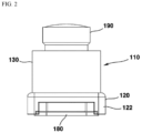
- FIG. 2 is a plan view illustrating a side surface of a camera module according to a first embodiment of the present invention
- FIG. 3 is an exploded perspective view of a camera module according to a first embodiment of the present invention
- FIG. 4 is an exploded perspective view of a camera module illustrating FIG. 3 from another angle
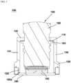
- FIG. 5 is a cross-sectional view taken along line A-A' of FIG. 1
- FIG. 6 is a graph comparing a change in distance between an image sensor and a lens for each temperature of a camera module according to a first embodiment of the present invention and a camera module according to the prior art.
- a camera module 100 may comprise: a housing 110 ; a lens module 190 ; a printed circuit board 180 ; and a coupling member 170 , but it may be implemented excluding some of these configurations, and other additional configurations are not excluded.
- the camera module 100 may include a housing 110.
- the housing 110 may form the outer appearance of the camera module 100.
- the upper and lower surfaces of the housing 110 may be opened.
- the material of the housing 110 may include a plastic or resin.
- the lens module 190 may be disposed inside the housing 110.
- the housing 110 may include a front body 130 and a rear body 120.
- the front body 130 may be disposed at a front surface of the rear body 120.
- the rear body 120 may be disposed at a rear surface of the front body 130.
- the front body 130 and the rear body 120 may be formed as a single body, but is not limited thereto.
- the cross section of the front body 130 may be formed in a circular shape, and an opening 112 through which the lens 190 penetrates may be formed on an upper surface thereof.
- the front body 130 may include: a side part 131 forming a side surface; and a top part 132 that is bent inward from the top of the side part 131 to form an upper surface.
- the front body 130 may also be referred to as a lens holder in that it accommodates the lens 190 therein. At least a portion of the lens 190 may be disposed in a space inside the front body 130.
- the top part 132 may cover a portion of the space inside the housing 110.
- the top part 132 may be referred to as a bent part in that it is bent inward from an upper end of the side part 131.
- the rear body 120 may be disposed on a rear surface of the front body 130.
- a space 126 being communicated with a space inside the front body 130 may be formed inside the rear body 120.
- the space 126 may be partitioned from other regions by the second protrusion part 125.
- the rear body 120 may include a second protrusion part 125.
- the second protrusion part 125 may be formed to be protruded downward from a lower surface of the rear body 120.
- the cross-sectional shape of the second protrusion part 125 may be formed in a ring shape.
- the lower end of the second protrusion part 125 may be protruded more downward than other regions of the lower surface of the rear body 120.
- the lower surface of the second protrusion part 125 may be disposed to face an upper surface of the printed circuit board 180.
- the lower surface of the second protrusion part 125 may be in contact with an upper surface of the printed circuit board 180.
- a separate sealing member (not shown) is disposed on an outer side surface of the second protrusion part 125 and may prevent foreign substances from entering the space 126.
- the protruded direction of the second protrusion part 125 may correspond to an optical axis direction of the camera module 100.
- the lower end of the second protrusion part 125 may be coupled to an upper surface of the printed circuit board 180 through a third coupling member 125a.
- the distance between the lens 190 and the image sensor 182 may be adjusted through the third coupling member 125a.
- the third coupling member 125a may include epoxy or an O-ring.
- the thermal expansion coefficient of the third coupling member 125a may be smaller than that of the first coupling member 170 which will be described later.
- a coupling part may be disposed on a lower surface of the rear body 120.
- the coupling part may be disposed at each corner region of a lower surface of the rear body 120.
- the second protrusion part 125 may be disposed inside the coupling part.
- the separate sealing member may be interposed between the coupling part and the second protrusion part 125.
- the coupling part is for coupling with other housing, and a thread hole for screw-coupling may be formed on a lower surface.
- the other housing may be coupled to the coupling part through screws.
- the cross-sectional area of the rear body 120 may be larger than the cross-sectional area of the front body 130.
- the camera module 100 may include a printed circuit board 180.
- the printed circuit board 180 is formed in a plate shape and can be coupled to the housing 110, that is, to a lower surface of the rear body 120.
- An upper surface of the printed circuit board 180 may be in contact with a lower surface of the second protrusion part 125.
- At least one electronic component for driving the camera module 100 may be disposed on the printed circuit board 180.
- an image sensor 182 may be disposed on an upper surface of the printed circuit board 180.
- the image sensor 182 may be disposed to face the lens module 190 in an optical axis direction.
- the image sensor 182 may be disposed inside the space 126.
- the camera module 100 may include a lens module 190.
- the lens module 190 may be disposed inside the housing 110.
- the lens module 190 may include at least one lens.
- the lens module 190 includes a plurality of lenses, and the plurality of lenses may be disposed along an optical axis direction. Among them, the outermost lens is disposed to be protruded upward from the housing 110 and may be exposed upward from the housing 110.
- the lens module 190 may comprise: a first region 192 being protruded upward from the housing 110 ; a second region 195 being disposed in a space inside the housing 110 ; and a third region 193 being disposed between the first region 192 and the second region 195 and disposed inside the opening 112.
- the cross-sectional shape of the third region 190 may correspond to a cross-sectional shape of the opening 112.
- the cross-sectional area of the third region 190 may correspond to or be smaller than the cross-sectional area of the opening 112.
- the cross-sectional area of the third region 193 may be smaller than the cross-sectional area of the first region 192 or the second region 195.
- the first region 192 may be disposed outside the housing 110 and the second region 195 may be disposed in a space inside the housing 110.
- the lens module 190 may be disposed to face the image sensor 182 in an optical axis direction.
- the lens module 190 may include a first protrusion part 194.
- the first protrusion part 194 may be protruded outward from a side surface of the lens module 190.
- the cross section of the first protrusion part 194 may be formed in a ring shape.
- An end portion of the first protrusion part 194 being extended outward may be disposed more outward than the side surface of the lens module 190.
- the first protrusion part 194 may be disposed at a lower portion of the third region 193.
- the first protrusion part 194 may be disposed in a space inside the housing 110.
- the first protrusion part 194 may be disposed at a lower portion of the top part 132.
- An upper surface of the first protrusion part 194 may be disposed to face a lower surface of the top part 132.
- An upper surface of the first protrusion part 194 may be overlapped with a lower surface of the top part 132 in an up and down direction.
- the protruded direction of the first protrusion part 194 may be perpendicular to an optical axis direction of the camera module 100.
- the camera module 100 may include a coupling member 170.
- the coupling member 170 may be referred to as a first coupling member 170.
- the coupling member 170 may be disposed in a space inside the housing 110.
- the coupling member 170 may be disposed between the lens module 190 and the housing 110.
- the coupling member 170 may be disposed between the lower surface of the top part 132 and the upper surface of the first protrusion part 194.
- the coupling member 170 may have a ring-shaped cross section.
- the coupling member 170 may be referred to as an adhesive member in that it attaches the lens module 190 and the housing 110 to each other.
- the coupling member 170 may also be called a sealing member in that it seals a space between the lens module 190 and the housing 110.
- the material of the coupling member 170 may include at least one of an epoxy, a rubber, and a plastic.
- the coupling member 170 may be an epoxy applied between an upper surface of the first protrusion part 194 and a lower surface of the top part 132.
- the coupling member 170 not only prevents external foreign substances from entering the housing 110, but also can minimize the change in distance between the image sensor 182 and the lens module 190 due to a temperature change of the camera module 100.
- the housing 110 may be expanded due to material characteristics of the housing 110. According to this, based on FIG. 5 , the housing 110 may be elongated in an up and down direction, and a distance between the image sensor 182 and the lens module 190 in an optical axis direction may be increased. However, according to the present embodiment, the coupling member 170 also expands due to high temperature, and as a result, the distance between the lens module 190 and the image sensor 182 may be reduced by the expansion of the housing 110.
- the housing 110 may contract. According to this, based on FIG. 5 , the housing 110 may be shortened in an up and down direction, and a distance between the image sensor 182 and the lens module 190 in an optical axis direction may be reduced. At this time, the coupling member 170 is contracted by low temperature, and as a result, the shortened distance between the lens module 190 and the image sensor 182 may be expanded by contraction of the housing 110.
- the distance between the lens module 190 and the image sensor 182 in the opposite direction by changing the distance between the lens module 190 and the image sensor 182 in the opposite direction by the deformation of the coupling member 170 as much as the change in the distance between the lens module 190 and the image sensor 182 due to the deformation of the housing 110 according to a temperature change, the distance between the image sensor 182 and the lens module 190 can be kept constant.
- the material of the coupling member 170 may be selected to a level capable of compensating for the temperature-induced deformation of the housing 110 in consideration of the thermal expansion coefficient of the housing 110.
- the thermal expansion coefficient of the first coupling member 170 may be greater than the thermal expansion coefficient of the third coupling member 125a.
- the thermal expansion coefficient of the first coupling member 170 may have a value 2 to 6 times greater than the thermal expansion coefficient of the third coupling member 125a.
- the above-described ratio of thermal expansion coefficients of the first coupling member 170 and the third coupling member 125a may be defined under an environment where the temperature range of a region in which the camera module 10 is disposed is -40 degrees to 105 degrees.
- the thermal expansion coefficient is measured through a thermo mechanical analyzer (TMA) device, through the above-described thermal expansion coefficient ratio of the first coupling member 170 and the third coupling member 125a, the change in distance between the lens module 190 and the image sensor 182 of the camera module 10 can be minimized under different environmental conditions.
- TMA thermo mechanical analyzer
- the first coupling member 170 when the first coupling member 170 expands, the first coupling member 170 can control the distance of the lens module 190 from the image sensor 182, and when the first coupling member 170 is thermally contracted, the first coupling member 170 may control the approaching of the lens module 190 to the image sensor 182.
- the thickness of the first coupling member 170 may be thicker than the thickness of the third coupling member 125a.
- the thickness of the first coupling member 170 may be 0.5 mm to 1.0 mm
- the thickness of the third coupling member 125a may be 0.2 mm to 0.5 mm.
- FIG. 7 is a perspective view of a camera module according to a second embodiment of the present invention.
- FIG. 8 is a cross-sectional view of a camera module according to a second embodiment of the present invention.
- a camera module 200 may include: a housing; a lens module 190 ; a printed circuit board 180 ; a coupling member 170 ; and a second coupling member 250.
- a housing according to the present embodiment may be formed by coupling the lens holder 230 and the rear body 220.
- the lens holder 230 may replace the front body 130 of the camera module 100 according to a first embodiment.
- the rear body 220 may replace the rear body 120 of the camera module 100 according to a first embodiment.
- the lens holder 230 may include an upper surface portion 232 and a side surface portion 231, and the rear body 220 may include configurations related to the second protrusion part 125 and the coupling part inside the rear body 120 according to a first embodiment.
- the lens holder 230 and the rear body 220 may be spaced apart from each other. Accordingly, a separation part 229 may be formed on a side surface of the housing. The separation part 229 may be disposed to penetrate the inner surface from the outer surface of the housing. A lower end of the lens holder 230 and an upper end of the rear body 220 may be spaced apart from each other by the separation part 229. The separation part 229 may be disposed in a boundary region between the lens holder 230 and the rear body 220. The separation part 229 may have a hole shape penetrating the inner surface from the outer surface of the housing forming the outer shape of the camera module 10.
- a second coupling member 250 may be disposed in the separation part 229.
- the second coupling member 250 is formed in a ring shape and can be accommodated inside the separation part 229.
- an outer surface of the second coupling member 250 may be protruded more outward than a side surface of the lens holder 230.
- an inner surface of the second coupling member 250 may be protruded more inward than an inner surface of the space inside the lens holder 230.
- the material of the second coupling member 250 may include at least one among an epoxy, a rubber, and a plastic.
- the second coupling member 250 may be an epoxy applied between the lens holder 230 and the rear body 220.
- a lower end of the lens module 190 may be disposed lower than the second coupling member 250 in an optical axis direction.
- the coupling member 170 of the first embodiment described above may be referred to as the first coupling member 170 in the present embodiment.
- the second coupling member 250 not only couples the lens holder 230 and the rear body 220 to each other, but also can minimize the change in distance between the image sensor 182 and the lens module 190 due to the temperature change of the camera module 200.
- the lens holder 230 and the second coupling member 250 may be expanded due to material characteristics of the lens holder 230 and the second coupling member 250. According to this, based on FIG. 8 , the lens holder 230 and the second coupling member 250 become longer in an up and down (optical axis) direction, and the distance between the image sensor 182 and the lens module 190 in an optical axis direction can be lengthened, but according to this embodiment, the first coupling member 170 is also expanded due to high temperature, and as a result, the distance between the lens module 190 and the image sensor 182 may be reduced by expansion of the lens module 230 and the second coupling member 250.
- the lens holder 230 and the second coupling member 250 may contract. According to this, based on FIG. 8 , the lens holder 230 and the second coupling member 250 become shortened in an up and down (optical axis) direction, and the distance between the image sensor 182 and the lens module 190 in an optical axis may become shortened. At this time, the first coupling member 170 is contracted by the low temperature, and as a result, due to the contraction of the lens holder 230, the distance between the lens module 190 and the image sensor 182 that has been shortened can be expanded.
- the thermal expansion coefficient of the first coupling member 170 is formed to be greater than the thermal expansion coefficient of the second coupling member 250, the distance change value between the lens module 190 and the image sensor 182 by the first coupling member 170 can be adjusted to accommodate the distance change value between the lens module 190 and the image sensor 182 caused by the lens holder 230 and the second coupling member 250.
- the thermal expansion coefficient of the first coupling member 170 may have a value 2 to 6 times greater than the thermal expansion coefficient of the second coupling member 250.
- the above-described ratio of thermal expansion coefficients of the first coupling member 170 and the second coupling member 250 may be defined under an environment in a region where the camera module 10 is disposed in which the temperature range is -40 degrees to 105 degrees.
- the thermal expansion coefficient is measured through a thermo mechanical analyzer (TMA) device, the distance between the lens module 190 and the image sensor 182 of the camera module 10 can be maintained constant under different environmental conditions through the above-described thermal expansion coefficient ratio of the first coupling member 170 and the second coupling member 250.
- TMA thermo mechanical analyzer
- the thickness of the first coupling member 170 may be thicker than the thickness of the second coupling member 250.
- the thickness of the first coupling member 170 may be 0.5 mm to 1.0 mm
- the thickness of the second coupling member 250 may be 0.2 mm to 0.5 mm.
Landscapes
- Physics & Mathematics (AREA)
- General Physics & Mathematics (AREA)
- Optics & Photonics (AREA)
- Engineering & Computer Science (AREA)
- Multimedia (AREA)
- Signal Processing (AREA)
- Lens Barrels (AREA)
- Studio Devices (AREA)
- Structure And Mechanism Of Cameras (AREA)
Applications Claiming Priority (2)
| Application Number | Priority Date | Filing Date | Title |
|---|---|---|---|
| KR1020200136644A KR20220052557A (ko) | 2020-10-21 | 2020-10-21 | 카메라 모듈 |
| PCT/KR2021/014246 WO2022086055A1 (fr) | 2020-10-21 | 2021-10-14 | Module de caméra |
Publications (2)
| Publication Number | Publication Date |
|---|---|
| EP4236292A1 true EP4236292A1 (fr) | 2023-08-30 |
| EP4236292A4 EP4236292A4 (fr) | 2024-09-11 |
Family
ID=81290780
Family Applications (1)
| Application Number | Title | Priority Date | Filing Date |
|---|---|---|---|
| EP21883126.1A Pending EP4236292A4 (fr) | 2020-10-21 | 2021-10-14 | Module de caméra |
Country Status (6)
| Country | Link |
|---|---|
| US (1) | US12591103B2 (fr) |
| EP (1) | EP4236292A4 (fr) |
| JP (1) | JP2023546586A (fr) |
| KR (1) | KR20220052557A (fr) |
| CN (1) | CN116529668B (fr) |
| WO (1) | WO2022086055A1 (fr) |
Families Citing this family (4)
| Publication number | Priority date | Publication date | Assignee | Title |
|---|---|---|---|---|
| JP2023090254A (ja) | 2021-12-17 | 2023-06-29 | キヤノン株式会社 | 撮像装置 |
| JP7770900B2 (ja) | 2021-12-17 | 2025-11-17 | キヤノン株式会社 | レンズ装置および撮像装置 |
| JP7814912B2 (ja) * | 2021-12-17 | 2026-02-17 | キヤノン株式会社 | 撮像装置 |
| JP7814913B2 (ja) | 2021-12-17 | 2026-02-17 | キヤノン株式会社 | レンズモジュール、撮像装置 |
Family Cites Families (18)
| Publication number | Priority date | Publication date | Assignee | Title |
|---|---|---|---|---|
| US7161730B2 (en) * | 2004-09-27 | 2007-01-09 | Idc, Llc | System and method for providing thermal compensation for an interferometric modulator display |
| JPWO2007063932A1 (ja) * | 2005-12-01 | 2009-05-07 | パナソニック株式会社 | レンズ鏡筒 |
| KR100813211B1 (ko) * | 2006-12-08 | 2008-03-13 | 주식회사 엠씨넥스 | 카메라 모듈 |
| TWI399567B (zh) * | 2007-06-01 | 2013-06-21 | Hon Hai Prec Ind Co Ltd | 鏡頭模組及相機模組 |
| JP2008304641A (ja) * | 2007-06-06 | 2008-12-18 | Sumitomo Electric Ind Ltd | レンズユニット、撮像装置及び画像処理システム |
| CN105103026B (zh) * | 2013-04-09 | 2017-05-31 | 富士胶片株式会社 | 摄像装置 |
| JP6094423B2 (ja) * | 2013-08-09 | 2017-03-15 | ミツミ電機株式会社 | レンズホルダ駆動装置、カメラモジュール、およびカメラ付き携帯端末 |
| KR102052760B1 (ko) | 2014-07-17 | 2019-12-09 | 삼성전기주식회사 | 렌즈 모듈 및 이를 포함하는 카메라 모듈 |
| JP6416269B2 (ja) * | 2014-08-26 | 2018-10-31 | シャープ株式会社 | カメラモジュール |
| JP6391122B2 (ja) * | 2015-10-26 | 2018-09-19 | カンタツ株式会社 | レンズアセンブリおよび撮像装置 |
| US10732488B2 (en) * | 2016-01-12 | 2020-08-04 | Lg Innotek Co., Ltd. | Holder assembly for camera module, camera module having same, and waterproof connector |
| KR102489665B1 (ko) | 2016-01-12 | 2023-01-18 | 엘지이노텍 주식회사 | 카메라 모듈용 홀더 어셈블리 및 이를 갖는 카메라 모듈 |
| WO2018053181A1 (fr) * | 2016-09-14 | 2018-03-22 | Fotonation Cayman Limited | Systèmes optiques pour caméras incorporant des éléments de lentille formés de façon séparée et ensuite liés à des substrats à faible cte |
| TWI651001B (zh) * | 2017-12-25 | 2019-02-11 | 群光電子股份有限公司 | 自動補償焦距之攝像裝置 |
| KR101985621B1 (ko) * | 2018-07-11 | 2019-06-03 | 장영근 | 렌즈 홀더 |
| US12197110B2 (en) * | 2019-03-29 | 2025-01-14 | Apple Inc. | Lens holder to compensate for optical focal shift by thermo-mechanical expansion |
| JP6821833B2 (ja) | 2020-01-07 | 2021-01-27 | マクセル株式会社 | レンズユニット及び撮像装置 |
| KR102516772B1 (ko) * | 2021-02-10 | 2023-03-31 | 삼성전기주식회사 | 카메라 모듈 |
-
2020
- 2020-10-21 KR KR1020200136644A patent/KR20220052557A/ko active Pending
-
2021
- 2021-10-14 CN CN202180071838.8A patent/CN116529668B/zh active Active
- 2021-10-14 WO PCT/KR2021/014246 patent/WO2022086055A1/fr not_active Ceased
- 2021-10-14 EP EP21883126.1A patent/EP4236292A4/fr active Pending
- 2021-10-14 JP JP2023524154A patent/JP2023546586A/ja active Pending
- 2021-10-14 US US18/247,364 patent/US12591103B2/en active Active
Also Published As
| Publication number | Publication date |
|---|---|
| WO2022086055A1 (fr) | 2022-04-28 |
| CN116529668A (zh) | 2023-08-01 |
| US20230418020A1 (en) | 2023-12-28 |
| US12591103B2 (en) | 2026-03-31 |
| KR20220052557A (ko) | 2022-04-28 |
| EP4236292A4 (fr) | 2024-09-11 |
| CN116529668B (zh) | 2026-04-21 |
| JP2023546586A (ja) | 2023-11-06 |
Similar Documents
| Publication | Publication Date | Title |
|---|---|---|
| US12591103B2 (en) | Camera module | |
| KR102902591B1 (ko) | 카메라 모듈 | |
| US20070031137A1 (en) | Optical module comprising a spacer element between the housing of a semiconductor element and a lens unit | |
| CN105791642B (zh) | 摄像头模块和用于车辆的摄像头 | |
| KR20140073195A (ko) | 카메라 모듈 | |
| US20250334859A1 (en) | Camera module | |
| KR20250166796A (ko) | 카메라 모듈 | |
| US12309480B2 (en) | Camera module | |
| KR102814812B1 (ko) | 카메라 모듈 | |
| KR20230029076A (ko) | 카메라 모듈 | |
| US7570439B2 (en) | Optical module and optical system | |
| US11821785B2 (en) | Optical sensor assembly and front cover of optical sensor assembly | |
| US20250172855A1 (en) | Camera module | |
| KR20230009132A (ko) | 카메라 모듈 | |
| KR20230068075A (ko) | 카메라 모듈 | |
| US20240348901A1 (en) | Camera module | |
| KR102912826B1 (ko) | 카메라 모듈 | |
| US20240004271A1 (en) | Camera module | |
| KR102353920B1 (ko) | 차량용 카메라 | |
| KR20220166600A (ko) | 카메라 모듈 | |
| KR20220000091A (ko) | 카메라 모듈 | |
| KR20230007096A (ko) | 카메라 모듈 | |
| KR20250147190A (ko) | 차량용 카메라 장치 | |
| KR20230155811A (ko) | 카메라 모듈 | |
| KR20240041851A (ko) | 카메라 모듈 |
Legal Events
| Date | Code | Title | Description |
|---|---|---|---|
| STAA | Information on the status of an ep patent application or granted ep patent |
Free format text: STATUS: THE INTERNATIONAL PUBLICATION HAS BEEN MADE |
|
| PUAI | Public reference made under article 153(3) epc to a published international application that has entered the european phase |
Free format text: ORIGINAL CODE: 0009012 |
|
| STAA | Information on the status of an ep patent application or granted ep patent |
Free format text: STATUS: REQUEST FOR EXAMINATION WAS MADE |
|
| 17P | Request for examination filed |
Effective date: 20230418 |
|
| AK | Designated contracting states |
Kind code of ref document: A1 Designated state(s): AL AT BE BG CH CY CZ DE DK EE ES FI FR GB GR HR HU IE IS IT LI LT LU LV MC MK MT NL NO PL PT RO RS SE SI SK SM TR |
|
| DAV | Request for validation of the european patent (deleted) | ||
| DAX | Request for extension of the european patent (deleted) | ||
| REG | Reference to a national code |
Ref country code: DE Ref legal event code: R079 Free format text: PREVIOUS MAIN CLASS: H04N0005225000 Ipc: H04N0023550000 |
|
| A4 | Supplementary search report drawn up and despatched |
Effective date: 20240813 |
|
| RIC1 | Information provided on ipc code assigned before grant |
Ipc: G02B 27/00 20060101ALI20240807BHEP Ipc: H04N 23/57 20230101ALI20240807BHEP Ipc: G03B 17/12 20210101ALI20240807BHEP Ipc: G02B 7/02 20210101ALI20240807BHEP Ipc: H04N 23/55 20230101AFI20240807BHEP |
|
| GRAP | Despatch of communication of intention to grant a patent |
Free format text: ORIGINAL CODE: EPIDOSNIGR1 |
|
| STAA | Information on the status of an ep patent application or granted ep patent |
Free format text: STATUS: GRANT OF PATENT IS INTENDED |
|
| RIC1 | Information provided on ipc code assigned before grant |
Ipc: H04N 23/55 20230101AFI20251128BHEP Ipc: H04N 23/52 20230101ALI20251128BHEP Ipc: H04N 23/57 20230101ALI20251128BHEP Ipc: G02B 7/02 20210101ALI20251128BHEP Ipc: G03B 17/12 20210101ALI20251128BHEP Ipc: G02B 27/00 20060101ALI20251128BHEP |
|
| INTG | Intention to grant announced |
Effective date: 20251216 |
|
| GRAS | Grant fee paid |
Free format text: ORIGINAL CODE: EPIDOSNIGR3 |
|
| GRAA | (expected) grant |
Free format text: ORIGINAL CODE: 0009210 |
|
| STAA | Information on the status of an ep patent application or granted ep patent |
Free format text: STATUS: THE PATENT HAS BEEN GRANTED |