EP4236343B1 - Panneau de raccordement avec retrait de la cassette de levage - Google Patents
Panneau de raccordement avec retrait de la cassette de levage Download PDFInfo
- Publication number
- EP4236343B1 EP4236343B1 EP23175576.0A EP23175576A EP4236343B1 EP 4236343 B1 EP4236343 B1 EP 4236343B1 EP 23175576 A EP23175576 A EP 23175576A EP 4236343 B1 EP4236343 B1 EP 4236343B1
- Authority
- EP
- European Patent Office
- Prior art keywords
- cassette
- rail
- projection
- along
- transverse direction
- Prior art date
- Legal status (The legal status is an assumption and is not a legal conclusion. Google has not performed a legal analysis and makes no representation as to the accuracy of the status listed.)
- Active
Links
Images




Classifications
-
- H—ELECTRICITY
- H04—ELECTRIC COMMUNICATION TECHNIQUE
- H04Q—SELECTING
- H04Q1/00—Details of selecting apparatus or arrangements
- H04Q1/02—Constructional details
- H04Q1/13—Patch panels for monitoring, interconnecting or testing circuits, e.g. patch bay, patch field or jack field; Patching modules
-
- G—PHYSICS
- G02—OPTICS
- G02B—OPTICAL ELEMENTS, SYSTEMS OR APPARATUS
- G02B6/00—Light guides; Structural details of arrangements comprising light guides and other optical elements, e.g. couplings
- G02B6/44—Mechanical structures for providing tensile strength and external protection for fibres, e.g. optical transmission cables
- G02B6/4439—Auxiliary devices
- G02B6/444—Systems or boxes with surplus lengths
- G02B6/4452—Distribution frames
- G02B6/44526—Panels or rackmounts covering a whole width of the frame or rack
-
- G—PHYSICS
- G02—OPTICS
- G02B—OPTICAL ELEMENTS, SYSTEMS OR APPARATUS
- G02B6/00—Light guides; Structural details of arrangements comprising light guides and other optical elements, e.g. couplings
- G02B6/44—Mechanical structures for providing tensile strength and external protection for fibres, e.g. optical transmission cables
- G02B6/4439—Auxiliary devices
- G02B6/444—Systems or boxes with surplus lengths
- G02B6/4453—Cassettes
- G02B6/4455—Cassettes characterised by the way of extraction or insertion of the cassette in the distribution frame, e.g. pivoting, sliding, rotating or gliding
-
- H—ELECTRICITY
- H04—ELECTRIC COMMUNICATION TECHNIQUE
- H04Q—SELECTING
- H04Q1/00—Details of selecting apparatus or arrangements
- H04Q1/02—Constructional details
- H04Q1/023—Constructional details using sliding mechanisms for accessing the interior of the apparatus
-
- G—PHYSICS
- G02—OPTICS
- G02B—OPTICAL ELEMENTS, SYSTEMS OR APPARATUS
- G02B6/00—Light guides; Structural details of arrangements comprising light guides and other optical elements, e.g. couplings
- G02B6/44—Mechanical structures for providing tensile strength and external protection for fibres, e.g. optical transmission cables
- G02B6/4439—Auxiliary devices
- G02B6/444—Systems or boxes with surplus lengths
- G02B6/44528—Patch-cords; Connector arrangements in the system or in the box
Definitions
- the present subject matter relates generally to fiber optic patch panels or enclosures for pre-terminated cassette modules.
- a patch panel in a first example embodiment, includes a cabinet and a cassette.
- a pair of cassette guides is positioned within the cabinet.
- the pair of cassette guides are spaced along a lateral direction such that the cassette is receivable between the pair of cassette guides.
- the cassette is slidable along a transverse direction on the pair of cassette guides.
- the transverse direction is perpendicular to the lateral direction.
- At least one of the pair of cassette guides includes a first rail and a second rail that are spaced apart along a vertical direction that is perpendicular to the lateral and transverse directions.
- the cassette is slidable along the transverse direction between the first and second rails.
- Each end of the first rail is cantilevered such that each end of the first rail is moveable along the vertical direction.
- a patch panel in a second example embodiment, includes a cabinet and a cassette.
- a pair of cassette guides is positioned within the cabinet.
- the pair of cassette guides are spaced along a lateral direction such that the cassette is receivable between the pair of cassette guides.
- the cassette is slidable along a transverse direction on the pair of cassette guides.
- the transverse direction is perpendicular to the lateral direction.
- At least one of the pair of cassette guides includes a first rail and a second rail that are spaced apart along a vertical direction that is perpendicular to the lateral and transverse directions.
- the cassette is slidable along the transverse direction between the first and second rails.
- Each end of the first rail is cantilevered such that each end of the first rail is moveable along the vertical direction.
- Each end of the second rail is not cantilevered such that each end of the second rail is fixed along the vertical direction.
- the first rail is elastically deformable such that each end of the first rail is moveable along the vertical direction by no less than three millimeters.
- FIGS. 1 through 3 are perspective views of a patch panel 100 according to an example embodiment of the present subject matter.
- patch panel 100 includes a cabinet or enclosure 110.
- Enclosure 110 may include a top panel 112 and a front panel 114.
- top panel 112 is removable to facilitate access to components within enclosure 110, e.g., at the rear of enclosure 110.
- front panel 114 is rotatable and may open and close. Thus, front panel 114 may facilitate access to components within enclosure 110, e.g., at the front of enclosure 110.
- patch panel 100 includes a plurality of cassette guides 120 and a plurality of cassettes 130.
- cassettes 130 may be modular and suitable for patch, patch & splice, wavelength-division-multiplexing (WDM), and splitter applications.
- WDM wavelength-division-multiplexing
- each cassette 130 may include connectors (such as LC connectors, MPO connecters, etc.) at a front and a rear of the cassette 130, and fibers within the cassette 130 may extend between the various connectors at the front and rear of the cassette 130.
- patch panel 100 includes features for regulating movement of cassettes 130 on cassette guides 120. Such features may facilitate access to cassettes 130 and thereby assist a user with connecting optical fiber cables to cassettes 130.
- patch panel 100 defines a vertical direction V, a lateral direction L and a transverse direction T.
- the vertical, lateral and transverse directions V, L, T are mutually perpendicular and form an orthogonal direction system.
- Cassettes 130 may be mounted on cassette guides 120 within enclosure 110 such that cassettes 130 are slidable relative to cassette guides 120 along the transverse direction T.
- all of cassettes 130 are shown in a retracted position on cassette guides 120 in FIG. 2 .
- one of cassettes 130 is shown in an extend position on cassette guides 120 with the rest of cassettes 130 shown in the retracted position in FIG. 3 .
- the extended position may facilitate access to perform moves, adds, and/or changes with front side patch cords.
- Cassette guides 120 are positioned within enclosure 110.
- cassette guides 120 are mounted within enclosure 110 such that cassette guides 120 are fixed relative to enclosure 110.
- cassette guides 120 may be mounted to enclosure 110 with thermal staking, ultrasonically welding, adhesive, tape and/or fasteners.
- patch panel 100 may not include a tray or drawer for slidably mounting cassette guides 120 within enclosure 110.
- patch panel 100 may include a tray or drawer, and cassette guides 120 may be mounted on the tray or drawer such that cassette guides 120 are movable relative to enclosure 110, e.g., along the transverse direction T, on the tray or drawer.
- patch panel 100 is shown with four cassette guides 120 and six cassettes 130.
- the four cassette guides 120 support the six cassettes 130 in two columns within enclosure 110. It will be understood that, while shown in FIGS. 2 and 3 with four cassette guides 120 and six cassettes 130, the particular number of cassette guides 120 and cassettes 130 is provided by way of example only. In alternative example embodiments, patch panel 100 may include any suitable number of cassette guides 120 and cassettes 130 depending upon the particular application.
- Each cassette 130 is slidable between two cassette guides 120.
- cassette guides 120 are spaced along the lateral direction L within enclosure 110, and cassettes 130 is receivable between cassette guides 120, e.g., along the lateral direction L.
- Cassette guides 120 and cassettes 130 are described in greater detail below in the context of FIGS. 4 through 6 .
- a single cassette guide 120 and cassette 130 are shown and described for the sake of brevity.
- patch panel 100 may include multiple cassette guides 120 and cassettes 130.
- Each cassette guide 120 and/or cassette 130 of patch panel 100 may be configured and/or constructed in the same or similar manner to that described below.
- FIG. 4 is a side elevation view of a cassette guide 120
- FIG. 5 is a side elevation view of a cassette 130
- FIG. 6 is a partial, side elevation view of the cassette 130 arranged in a retracted position within the cassette guide 120.
- each cassette guide 120 may define three mounting bays 122 that are stacked along the vertical direction V.
- Each mounting bay 122 may support a respective cassette 130.
- three cassettes 130 may be stacked along the vertical direction V within mounting bays 122 on each cassette guide 120.
- cassette guide 120 includes a first rail 124 and a second rail 126.
- First and second rails 124, 126 define a respective one of mounting bays 122. While only two rails 124, 126 are described herein, it will be understood that cassette guide 120 may include other rails (not labeled) that define the other two mounting bays 122, as shown in FIG. 4 .
- Such other rails may be formed in the same or similar manner to that described below for first and second rails 124, 126 but are not described in greater detail below for the sake of brevity.
- First rail 124 and second rail 126 are spaced apart along the vertical direction V.
- cassette 130 is receivable between first and second rails 124, 126, as shown in FIG. 6 .
- cassette 130 is slidable along the transverse direction T between first and second rails 124, 126.
- first rail 124 and second rail 126 are spaced apart along the vertical direction V such that a side of cassette 130 is positioned between first and second rails 124, 126 and cassette 130 slides along the transverse direction T relative to cassette guide 120.
- Cassette guides 120 may be, e.g., molded, plastic cassette guides in certain example embodiments.
- each cassette guide 120 may be a separate, discrete piece of plastic.
- cassette guide 120 and cassette 130 include features for locking cassette 130 in a retracted or installed position (shown in FIG. 6 ) on cassette guide 120.
- each end 121 of first rail 124 is cantilevered.
- each end 121 of first rail 124 may be moveable along the vertical direction V.
- the ends 121 of first rail 124 moves along the vertical direction V to unlock cassette 130 from the retracted position on cassette guide 120 and allows cassette 130 to slide along the transverse direction T into an extended position (shown in FIG. 3 ) and/or allow cassette 130 to be removed from cassette guide 120 along the transverse direction T, as described in greater detail below.
- Each end of second rail 126 is not cantilevered, e.g., such that each end of second rail 126 is fixed along the vertical direction V.
- First rail 124 is elastically deformable to allow the ends 121 of first rail 124 to move along the vertical direction V to a suitable degree.
- first rail 124 is be elastically deformable such that each end 121 of first rail 124 is moveable along the vertical direction V by no less than three millimeters (3mm).
- cassette guide 120 e.g., first rail 124) may be constructed of a material with a suitable modulus of elasticity, such as a plastic, and/or a length of the portion of first rail 124 that is cantilevered may be no less than twelve millimeters (12 mm). Such features may advantageously allow selective locking of cassette 130 in the retracted position on cassette guide 120.
- cassette 130 may include a slide rail 132.
- Slide rail 132 is positioned on a side of cassette 130 and is receivable between first and second rails 124, 126 of cassette guide 120.
- slide rail 132 of cassette 130 may cooperate with first and second rails 124, 126 of cassette guide 120 to allow cassette 130 to slide along the transverse direction T relative to cassette guide 120.
- Cassette 130 may include another slide rail on the opposite side of cassette 130 that is constructed in the same or similar manner to that described below for slide rail 132.
- second rail 126 may include a first projection 128 and a second projection 129.
- First and second projections 128, 129 of second rail 126 may be spaced apart, e.g., along the transverse direction T, on second rail 126.
- slide rail 132 may include a first projection 134 and a second projection 136.
- First and second projections 134, 136 of slide rail 132 may be spaced apart, e.g., along the transverse direction T, on slide rail 132.
- the projections 128, 129, 134, 136 may cooperate to lock cassette 130 in the retracted position on cassette guide 120.
- first projection 134 of slide rail 132 may be positioned against first projection 128 of second rail 126 when cassette 130 is in the retracted positon on cassette guide 120.
- second projection 136 of slide rail 132 may be positioned against second projection 129 of second rail 126 when cassette 130 is in the retracted positon on cassette guide 120.
- Interference between first projection 134 of slide rail 132 and first projection 128 of second rail 126 as well as interference between second projection 136 of slide rail 132 and second projection 129 of second rail 126 may block movement of cassette 130 along the transverse direction T relative to cassette guide 120 when cassette 130 is in the retracted positon on cassette guide 120, e.g., and the cantilevered ends 121 of first rail 124 limit upward movement of slide rail 132.
- First projection 134 of slide rail 132 may be spaced from second projection 136 of slide rail 132 by a first distance D1, e.g., along the transverse direction T, as shown in FIG. 5 .
- first projection 128 of second rail 126 may be spaced from second projection 129 of second rail 126 by a second distance D2, e.g., along the transverse direction T, as shown in FIG. 4 .
- the first distance D1 may be less than the second distance D2.
- first and second projections 134, 136 of slide rail 132 may be positioned between first and second projections 128, 129 of second rail 126, e.g., along the transverse direction T, when cassette 130 is in the retracted positon on cassette guide 120.
- Such positioning may advantageously facilitate selective locking of cassette 130 in the retracted position on cassette guide 120, e.g., by allowing cassette 130 to be lifted upwardly along the vertical direction V to permit cassette 130 to slide along the transverse direction T relative to cassette guide 120.
- each end 121 of first rail 124 may be cantilevered such that each end 121 of first rail 124 extends over a respective one of first and second projections 128, 129 of second rail 126, e.g., along the transverse direction T.
- first rail 124 may define a length H, e.g., along the transverse direction T between the ends 121 of first rail 124.
- First projection 134 of slide rail 132 may also be spaced from second projection 136 of slide rail 132 by a gap G (i.e., the first distance D1 shown in FIG. 5 ), e.g., along the transverse direction T.
- first rail 124 may be no less than five millimeters (5 mm) greater than the gap G between first and second projections 134, 136 of slide rail 132. Such sizing may advantageously allow the cantilevered ends 121 of first rail 124 to assist with locking cassette 130 in the retracted position on cassette guide 120.
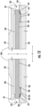
- FIG. 13 is a partial, side elevation view of cassette 130 and cassette guide 120.
- first projection 134 of slide rail 132 includes a planar locking surface 135.
- second projection 136 of slide rail 132 includes a planar locking surface 137.
- Planar locking surfaces 135, 137 of slide rail 132 may be oriented perpendicular to the transverse direction T.
- Planar locking surface 135 of first projection 134 of slide rail 132 may also face away from planar locking surface 137 of second projection 136 of slide rail 132, e.g., along the transverse direction T.
- first projection 128 of second rail 126 may also include a planar locking surface 125
- second projection 129 of second rail 126 may also include a planar locking surface 127.
- Planar locking surfaces 125, 127 of second rail 126 may be oriented perpendicular to the transverse direction T.
- Planar locking surface 125 of first projection 128 of second rail 126 may face towards planar locking surface 127 of second projection 129 of second rail 126, e.g., along the transverse direction T.
- Planar locking surface 135 of first projection 134 of slide rail 132 may be positioned on or against planar locking surface 125 of first projection 128 of second rail 126 when cassette 130 is in the retracted positon on cassette guide 120.
- planar locking surface 137 of second projection 136 of slide rail 132 may be positioned on or against planar locking surface 127 of second projection 129 of second rail 126 when cassette 130 is in the retracted positon on cassette guide 120.
- planar locking surfaces 135, 137 of slide rail 132 may cooperate with planar locking surfaces 125, 127 of second rail 126 to lock cassette 130 is in the retracted positon on cassette guide 120, e.g., due to interference at the interfaces.
- first projection 134 of slide rail 132 also includes a sloped surface 138.
- second projection 136 of slide rail 132 includes a sloped surface 139. Sloped surface 138 of first projection 134 of slide rail 132 may be positioned opposite planar locking surface 135 of first projection 134 of slide rail 132, e.g., along the transverse direction T.
- sloped surface 139 of second projection 136 of slide rail 132 may be positioned opposite planar locking surface 137 of second projection 136 of slide rail 132, e.g., along the transverse direction T.
- slide rail 132 may further include a stop tab 133.
- Stop tab 133 may be positioned between first and second projections 134, 136 of slide rail 132, e.g., along the transverse direction T.
- Stop tab 133 may have planar locking surfaces (not labeled) formed in the same or similar manner to planar locking surfaces 135, 137 of slide rail 132. Stop tab 133 may engage first and second projections 134, 136 of slide rail 132 to limit translation of cassette 130, e.g., along the transverse direction T, as discussed in greater detail below.
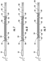
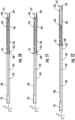
- FIGS. 7 through 12 are side elevation views of cassette 130 and cassette guide 120 in various stages of shifting from the retracted position ( FIG. 7 ) to the extended positon ( FIG. 10 ) to fully removed ( FIG. 12 ).
- Example steps for moving cassette 130 along the transverse direction T relative to cassette guide 120 will now be described in greater detail below in the context of FIGS. 7 through 12 .
- cassette 130 is shown in the retracted position on cassette guide 120.
- the retracted position may correspond to the position of cassette 130 on cassette guide 120 in which cassette 130 is locked within a mounting bay 122 ( FIG. 3 ).
- interference between first projection 134 of slide rail 132 and first projection 128 of second rail 126 as well as interference between second projection 136 of slide rail 132 and second projection 129 of second rail 126 may block movement of cassette 130 along the transverse direction T relative to cassette guide 120 when cassette 130 is in the retracted positon on cassette guide 120.
- a user of patch panel 100 may desire to shift cassette 130 to the extended positon ( FIG. 10 ) and/or to fully remove cassette 130 from cassette guide 120 ( FIG. 12 ).
- the user may move a handle 131 of cassette 130, e.g., upwardly along the vertical direction V.
- one end 121 of first rail 124 may elastically deform and move, e.g., along the vertical direction V.
- Such movement of first rail 124 may assist with disengaging first projection 134 of slide rail 132 from first projection 128 of second rail 126.
- planar locking surface 135 ( FIG. 13 ) of first projection 134 of slide rail 132 may be spaced from planar locking surface 125 ( FIG. 13 ) of first projection 128 of second rail 126 along the vertical direction V by lifting upwardly on handle 131 of cassette 130 and elastically deforming first rail 124.
- elastic deformation of first rail 124 may allow first projection 134 of slide rail 132 to disengage from first projection 128 of second rail 126 by moving upwardly along the vertical direction V.
- first projection 134 of slide rail 132 may move to the opposite side of first projection 128 of second rail 126 relative to the arrangement shown in FIGS. 7 and 8 .
- the user may continue to pull on handle 131 of cassette 130 to move cassette 130, e.g., along the transverse direction T, relative to cassette guide 120.
- stop tab 133 may impact first projection 128 of second rail 126 as the user continues to pull on handle 131 of cassette 130. Interference between stop tab 133 and first projection 128 of second rail 126 may block further movement of cassette 130 along the transverse direction T relative to cassette guide 120.
- the user may again move handle 131 of cassette 130, e.g., upwardly along the vertical direction V.
- the one end 121 of first rail 124 may elastically deform and move, e.g., along the vertical direction V.
- Such movement of first rail 124 may assist with disengaging stop tab 133 from first projection 128 of second rail 126.
- the user may pull on handle 131 of cassette 130 to move cassette 130, e.g., along the transverse direction T, relative to cassette guide 120.
- stop tab 133 may move to the opposite side of first projection 128 of second rail 126 relative to the arrangement shown in FIGS. 10 and 11 .
- sloped surface 139 of second projection 136 of slide rail 132 may automatically allow second projection 136 of slide rail 132 to slide over first projection 128 of second rail 126, e.g., without requiring the user to lift upwardly on handle 131 of cassette 130.
- the user may continue to pull on handle 131 of cassette 130 to fully remove cassette 130 from cassette guide 120.
- first projection 128 of second rail 126 may automatically allow first and second projections 134, 136 of slide rail 132 to slide over first projection 128 of second rail 126, e.g., without requiring the user to lift upwardly on handle 131 of cassette 130.
- first and second projections 134, 136 of slide rail 132 may automatically allow first and second projections 134, 136 of slide rail 132 to slide over first projection 128 of second rail 126, e.g., without requiring the user to lift upwardly on handle 131 of cassette 130.
- the same or similar process may be used to remove cassette 130 from a rear of cassette guide 120.
- FIG. 14 is a perspective view of cassette 130.
- cassette 130 may include front adapters 140 and rear adapters 142 positioned at opposite ends of cassette 130.
- Cassette 130 may also include a transparent cover 144 that protects optical fibers (not shown) within cassette 130 while also allowing viewing of the optical fibers through the transparent cover 144.
- Fiber management slots 146 may be formed at the front and rear of cassette 130.
- FIG. 15 is a perspective view of a pair of cassettes 130 and a bridging connector 150.
- Bridging connector 150 may extend between and connect two adjacent cassettes 130, e.g., along the lateral direction L. Bridging connector 150 may couple the two cassettes 130 such that movement of cassettes 130, e.g., along the transverse direction T, is transferred between the two cassettes 130 via bridging connector 150.
- cassettes 130 may be installed and removed by single-hand manipulation for both front and rear install/release scenarios.
Landscapes
- Physics & Mathematics (AREA)
- General Physics & Mathematics (AREA)
- Optics & Photonics (AREA)
- Engineering & Computer Science (AREA)
- Computer Networks & Wireless Communication (AREA)
- Packaging Of Annular Or Rod-Shaped Articles, Wearing Apparel, Cassettes, Or The Like (AREA)
- Sheets, Magazines, And Separation Thereof (AREA)
- Light Guides In General And Applications Therefor (AREA)
- Warehouses Or Storage Devices (AREA)
Claims (7)
- Panneau de raccordement (100), comprenant :une armoire (110) ;une cassette (130) ;une paire de guides (120) de cassette positionnés à l'intérieur de l'armoire (110), la paire de guides (120) de cassette étant espacés le long d'une direction latérale (L) de sorte que la cassette (130) puisse être reçue entre la paire de guides (120) de cassette, la cassette (130) pouvant coulisser le long d'une direction transversale (T) sur la paire de guides (120) de cassette, la direction transversale (T) étant perpendiculaire à la direction latérale (L),dans lequel au moins l'un de la paire de guides (120) de cassette comprend un premier rail (124) et un deuxième rail (126) qui sont espacés le long d'une direction verticale (V) qui est perpendiculaire aux directions latérale et transversale (L, T), la cassette (130) coulissant le long de la direction transversale (T) entre les premier et deuxième rails (124, 126),le panneau de raccordement étant caractérisé en ce que chaque extrémité (121) du premier rail (124) est en porte-à-faux de sorte que chaque extrémité (121) du premier rail (124) soit mobile le long de la direction verticale (V), chaque extrémité du deuxième rail (126) n'est pas en porte-à-faux de sorte que chaque extrémité du deuxième rail (126) soit fixée le long de la direction verticale (V), et le premier rail (124) est déformable élastiquement de sorte que chaque extrémité (121) du premier rail (124) soit mobile le long de la direction verticale (V) d'au moins trois millimètres.
- Panneau de raccordement (100) selon la revendication 1, dans lequel :le deuxième rail (126) comprend une première saillie (128) et une deuxième saillie (129) espacées le long de la direction transversale (T) ; etla cassette (130) comprend un rail coulissant (132) pouvant être reçu entre les premier et deuxième rails (124, 126), le rail coulissant (132) comprenant une première saillie (134) et une deuxième saillie (136) espacées le long de la direction transversale (T) ;la première saillie (134) du rail coulissant (132) étant positionnée contre la première saillie (128) du deuxième rail (126) lorsque la cassette (130) est dans une position installée sur la paire de guides (120) de cassette ; etla deuxième saillie (136) du rail coulissant (132) étant positionnée contre la deuxième saillie (129) du deuxième rail (126) lorsque la cassette (130) est dans la position installée sur la paire de guides (120) de cassette.
- Panneau de raccordement (100) selon la revendication 2, dans lequel :la première saillie (134) du rail coulissant (132) est espacée de la deuxième saillie (129) du rail coulissant (132) d'une première distance le long de la direction transversale (T) ;la première saillie (128) du deuxième rail (126) est espacée de la deuxième saillie (129) du deuxième rail (126) d'une deuxième distance le long de la direction transversale (T) ; etla première distance est inférieure à la deuxième distance.
- Panneau de raccordement (100) selon la revendication 2, dans lequel :chacune des première et deuxième saillies (134, 136) du rail coulissant (132) comprend une surface de verrouillage plane (135, 137) respective qui est orientée perpendiculairement à la direction transversale (T) ;chacune des première et deuxième saillies (128, 129) du deuxième rail (126) comprend une surface de verrouillage plane (125, 127) respective qui est orientée perpendiculairement à la direction transversale (T) ;la surface de verrouillage plane (135) de la première saillie (134) du rail coulissant (132) est opposée à la surface de verrouillage plane (137) de la deuxième saillie (136) du rail coulissant (132) le long de la direction transversale (T) ; etla surface de verrouillage plane (125) de la première saillie (128) du deuxième rail (126) est tournée vers la surface de verrouillage plane (127) de la deuxième saillie (129) du deuxième rail (126) le long de la direction transversale (T).
- Panneau de raccordement (100) selon la revendication 4, dans lequel :chacune des première et deuxième saillies (134, 136) du rail coulissant (132) comprend une surface inclinée (138, 139) respective ;la surface inclinée (138) de la première saillie (134) du rail coulissant (132) est positionnée à l'opposé de la surface de verrouillage plane (135) de la première saillie (134) du rail coulissant (132) le long de la direction transversale (T) ; etla surface inclinée (139) de la deuxième saillie (136) du rail coulissant (132) est positionnée à l'opposé de la surface de verrouillage plane (137) de la deuxième saillie (136) du rail coulissant (132) le long de la direction transversale (T).
- Panneau de raccordement (100) selon la revendication 2, dans lequel le rail coulissant (132) comprend en outre une patte d'arrêt (133) positionnée entre les première et deuxième saillies (134, 136) du rail coulissant (132) le long de la direction transversale (T).
- Panneau de raccordement (100) selon la revendication 2, dans lequel chaque extrémité (121) du premier rail (124) est en porte-à-faux de sorte que chaque extrémité (121) du premier rail (124) s'étende sur une saillie respective parmi les première et deuxième saillies (128, 129) du deuxième rail (126) le long de la direction transversale (T).
Priority Applications (1)
| Application Number | Priority Date | Filing Date | Title |
|---|---|---|---|
| EP23175576.0A EP4236343B1 (fr) | 2019-04-17 | 2019-04-17 | Panneau de raccordement avec retrait de la cassette de levage |
Applications Claiming Priority (3)
| Application Number | Priority Date | Filing Date | Title |
|---|---|---|---|
| EP23175576.0A EP4236343B1 (fr) | 2019-04-17 | 2019-04-17 | Panneau de raccordement avec retrait de la cassette de levage |
| PCT/US2019/027892 WO2020214161A1 (fr) | 2019-04-17 | 2019-04-17 | Panneau de raccordement avec retrait de la cassette de levage |
| EP19721935.5A EP3957078B1 (fr) | 2019-04-17 | 2019-04-17 | Panneau de raccordement avec retrait de la cassette de levage |
Related Parent Applications (2)
| Application Number | Title | Priority Date | Filing Date |
|---|---|---|---|
| EP19721935.5A Division-Into EP3957078B1 (fr) | 2019-04-17 | 2019-04-17 | Panneau de raccordement avec retrait de la cassette de levage |
| EP19721935.5A Division EP3957078B1 (fr) | 2019-04-17 | 2019-04-17 | Panneau de raccordement avec retrait de la cassette de levage |
Publications (3)
| Publication Number | Publication Date |
|---|---|
| EP4236343A2 EP4236343A2 (fr) | 2023-08-30 |
| EP4236343A3 EP4236343A3 (fr) | 2023-10-18 |
| EP4236343B1 true EP4236343B1 (fr) | 2025-03-12 |
Family
ID=66397465
Family Applications (2)
| Application Number | Title | Priority Date | Filing Date |
|---|---|---|---|
| EP19721935.5A Active EP3957078B1 (fr) | 2019-04-17 | 2019-04-17 | Panneau de raccordement avec retrait de la cassette de levage |
| EP23175576.0A Active EP4236343B1 (fr) | 2019-04-17 | 2019-04-17 | Panneau de raccordement avec retrait de la cassette de levage |
Family Applications Before (1)
| Application Number | Title | Priority Date | Filing Date |
|---|---|---|---|
| EP19721935.5A Active EP3957078B1 (fr) | 2019-04-17 | 2019-04-17 | Panneau de raccordement avec retrait de la cassette de levage |
Country Status (5)
| Country | Link |
|---|---|
| US (4) | US11237348B2 (fr) |
| EP (2) | EP3957078B1 (fr) |
| CN (1) | CN112106383B (fr) |
| MX (1) | MX2021012546A (fr) |
| WO (1) | WO2020214161A1 (fr) |
Families Citing this family (5)
| Publication number | Priority date | Publication date | Assignee | Title |
|---|---|---|---|---|
| CN112106383B (zh) | 2019-04-17 | 2024-03-12 | 欧博互联网网关有限责任公司 | 带提升盒移除的接线板 |
| US11740421B2 (en) | 2021-02-18 | 2023-08-29 | Commscope Technologies Llc | Communications panel system |
| US11971598B2 (en) | 2021-02-18 | 2024-04-30 | Commscope Technologies Llc | Tray arrangements for cassettes |
| EP4370958A4 (fr) * | 2021-07-16 | 2025-05-21 | CommScope Technologies LLC | Systèmes de panneaux avec cassettes coulissantes |
| WO2024216023A2 (fr) * | 2023-04-14 | 2024-10-17 | Clearfield, Inc. | Cassette de fibre optique modulaire |
Family Cites Families (136)
| Publication number | Priority date | Publication date | Assignee | Title |
|---|---|---|---|---|
| US4900123A (en) * | 1988-08-29 | 1990-02-13 | Gte Products Corporation | 1550 nm fiber distribution panel |
| US5339379A (en) | 1993-06-18 | 1994-08-16 | Telect, Inc. | Telecommunication fiber optic cable distribution apparatus |
| GB9314161D0 (en) | 1993-07-08 | 1993-08-18 | Rose Walter Gmbh & Co Kg | A multi-filament splice enclosure |
| US5490229A (en) | 1993-12-08 | 1996-02-06 | At&T Ipm Corp. | Slidably mounted optical fiber distribution tray |
| US5701380A (en) | 1996-06-24 | 1997-12-23 | Telect, Inc. | Fiber optic module for high density supply of patching and splicing |
| US5966492A (en) | 1997-12-19 | 1999-10-12 | Antec Corporation | Apparatus for storing and splicing optical fibers |
| US5978540A (en) | 1998-04-23 | 1999-11-02 | Antec Corporation | Apparatus for interconnecting optical fibers |
| US6215938B1 (en) | 1998-09-21 | 2001-04-10 | Adc Telecommunications, Inc. | Fiber optic cabinet and tray |
| US6456773B1 (en) | 1999-04-26 | 2002-09-24 | Ciena Corporation | Dispersion compensation module |
| US6438310B1 (en) | 2000-01-24 | 2002-08-20 | Adc Telecommunications, Inc. | Cable management panel with sliding drawer |
| US6647197B1 (en) | 2000-06-02 | 2003-11-11 | Panduit Corp. | Modular latch and guide rail arrangement for use in fiber optic cable management systems |
| US6944387B2 (en) | 2001-04-30 | 2005-09-13 | Telect, Inc. | Fiber optic connector tray system |
| US6792190B2 (en) | 2001-06-01 | 2004-09-14 | Telect, Inc. | High density fiber optic splitter/connector tray system |
| US6499609B2 (en) | 2001-06-04 | 2002-12-31 | Hyperchip Inc. | Compact shelf unit for electronic equipment rack |
| US7079744B2 (en) | 2001-07-06 | 2006-07-18 | Adc Telecommunications, Inc. | Cable management panel with sliding drawer and methods |
| KR100772365B1 (ko) * | 2001-11-15 | 2007-11-01 | 삼성전자주식회사 | 광 디스크 드라이브의 트레이 가이드 구조체 |
| JP3815606B2 (ja) | 2001-11-16 | 2006-08-30 | 河村電器産業株式会社 | 光配線盤 |
| US6677520B1 (en) | 2002-07-22 | 2004-01-13 | Adc Telecommunications, Inc. | Fanning tray |
| US6768860B2 (en) | 2002-12-05 | 2004-07-27 | Jds Uniphase Inc. | High density fiber optic module |
| JP4039673B2 (ja) | 2003-06-09 | 2008-01-30 | 河村電器産業株式会社 | 融着トレイ収納具 |
| US7171099B2 (en) | 2003-07-31 | 2007-01-30 | Adc Telecommunications, Inc. | Slide arrangement for cable drawer |
| US6944389B2 (en) | 2003-11-26 | 2005-09-13 | Corning Cable Systems Llc | Connector housing having a sliding tray with a hingeable portion |
| US7711233B2 (en) | 2005-06-13 | 2010-05-04 | Scientific-Atlanta, Inc. | Fiber optic cable enclosure assembly with slide out tray |
| JP4786294B2 (ja) | 2005-10-27 | 2011-10-05 | 株式会社ジャパンリーコム | 光ケーブル接続用クロージャにおける成端盤 |
| US7509015B2 (en) | 2006-07-26 | 2009-03-24 | Ortronics, Inc. | Secure fiber optic network cassette assembly |
| US7391952B1 (en) | 2006-08-31 | 2008-06-24 | Corning Cable Systems Llc | Pre-connectorized fiber optic cable network interconnection apparatus |
| US7428363B2 (en) | 2006-10-02 | 2008-09-23 | Emerson Network Power, Energy Systems, North America, Inc. | Distribution module for an optic fiber distribution hub |
| US7689089B2 (en) | 2006-10-11 | 2010-03-30 | Panduit Corp. | Release latch for pre-terminated cassette |
| US7570861B2 (en) | 2007-01-19 | 2009-08-04 | Adc Telecommunications, Inc. | Adapter panel with lateral sliding adapter arrays |
| US7509016B2 (en) | 2007-03-09 | 2009-03-24 | Adc Telecommunications, Inc. | Telecommunication rack unit tray |
| US8861918B2 (en) | 2007-09-07 | 2014-10-14 | Corning Cable Systems Llc | Fiber optic adapter module and tray |
| US7889961B2 (en) | 2008-03-27 | 2011-02-15 | Corning Cable Systems Llc | Compact, high-density adapter module, housing assembly and frame assembly for optical fiber telecommunications |
| US7715681B2 (en) | 2008-03-28 | 2010-05-11 | Adc Telecommunications, Inc. | Rear latch arrangement for sliding drawer |
| US8249410B2 (en) | 2008-04-25 | 2012-08-21 | Corning Cable Systems Llc | Connector housing for a communication network |
| US7945135B2 (en) | 2008-08-29 | 2011-05-17 | Corning Cable Systems Llc | Telescoping fiber optic module and related equipment |
| US8452148B2 (en) | 2008-08-29 | 2013-05-28 | Corning Cable Systems Llc | Independently translatable modules and fiber optic equipment trays in fiber optic equipment |
| US8326107B2 (en) | 2008-08-29 | 2012-12-04 | Corning Cable Systems Llc | Rear-slidable extension in a fiber optic equipment tray |
| US8184938B2 (en) | 2008-08-29 | 2012-05-22 | Corning Cable Systems Llc | Rear-installable fiber optic modules and equipment |
| US7856166B2 (en) | 2008-09-02 | 2010-12-21 | Corning Cable Systems Llc | High-density patch-panel assemblies for optical fiber telecommunications |
| US8433063B2 (en) | 2008-09-08 | 2013-04-30 | Ortronics, Inc. | Horizontal copper patching assembly |
| US7697811B2 (en) | 2008-09-08 | 2010-04-13 | Ortronics, Inc. | Horizontal fiber optic patching assembly |
| US8879882B2 (en) | 2008-10-27 | 2014-11-04 | Corning Cable Systems Llc | Variably configurable and modular local convergence point |
| TWM372950U (en) | 2009-03-31 | 2010-01-21 | Corning Cable Sys Llc | Optical fiber splitter mounting frame |
| ES2618575T3 (es) | 2009-05-21 | 2017-06-21 | Corning Optical Communications LLC | Equipo de fibra óptica con guías y carriles configurados con posiciones de parada |
| US9075216B2 (en) | 2009-05-21 | 2015-07-07 | Corning Cable Systems Llc | Fiber optic housings configured to accommodate fiber optic modules/cassettes and fiber optic panels, and related components and methods |
| US8538226B2 (en) | 2009-05-21 | 2013-09-17 | Corning Cable Systems Llc | Fiber optic equipment guides and rails configured with stopping position(s), and related equipment and methods |
| AU2015203581A1 (en) | 2009-05-21 | 2015-07-23 | Corning Optical Communications LLC | Fiber optic equipment supporting moveable fiber optic equipment tray(s) and module(s), and related equipment and methods |
| US8712206B2 (en) | 2009-06-19 | 2014-04-29 | Corning Cable Systems Llc | High-density fiber optic modules and module housings and related equipment |
| AU2010263046B2 (en) | 2009-06-19 | 2015-07-23 | Corning Cable Systems Llc | High fiber optic cable packing density apparatus |
| WO2010148336A1 (fr) | 2009-06-19 | 2010-12-23 | Corning Cable Systems Llc | Appareils à fibres optiques à large bande et à densité élevée et équipement et procédés associés |
| US8385710B2 (en) | 2009-11-12 | 2013-02-26 | Panduit Corp. | Fiber tray |
| US8208781B1 (en) | 2009-12-03 | 2012-06-26 | Adtran, Inc. | Fiber optic connector panel |
| US8625950B2 (en) | 2009-12-18 | 2014-01-07 | Corning Cable Systems Llc | Rotary locking apparatus for fiber optic equipment trays and related methods |
| WO2011100613A1 (fr) | 2010-02-12 | 2011-08-18 | Adc Telecommunications, Inc. | Systèmes de panneau à lames de communication |
| WO2011107180A1 (fr) * | 2010-03-02 | 2011-09-09 | Adc Gmbh | Module de télécommunication à fibre optique |
| US9075217B2 (en) | 2010-04-30 | 2015-07-07 | Corning Cable Systems Llc | Apparatuses and related components and methods for expanding capacity of fiber optic housings |
| US8385711B2 (en) | 2010-04-30 | 2013-02-26 | Corning Cable Systems Llc | Multi-configurable splice holder |
| US9632270B2 (en) | 2010-04-30 | 2017-04-25 | Corning Optical Communications LLC | Fiber optic housings configured for tool-less assembly, and related components and methods |
| US9519118B2 (en) | 2010-04-30 | 2016-12-13 | Corning Optical Communications LLC | Removable fiber management sections for fiber optic housings, and related components and methods |
| CN102870025A (zh) | 2010-04-30 | 2013-01-09 | 康宁光缆系统有限公司 | 具有可移除面板夹的光纤壳体 |
| US8705926B2 (en) | 2010-04-30 | 2014-04-22 | Corning Optical Communications LLC | Fiber optic housings having a removable top, and related components and methods |
| WO2011163464A2 (fr) | 2010-06-23 | 2011-12-29 | Adc Telecommunications, Inc. | Ensemble de télécommunications |
| CN101881870B (zh) | 2010-07-12 | 2011-11-09 | 武汉光迅科技股份有限公司 | 用于光纤线缆滑动抽屉的收紧控制机构 |
| WO2012052332A1 (fr) | 2010-10-18 | 2012-04-26 | Tyco Electronics Corporation India Pvt Limited | Améliorations apportées à des glissières doubles télescopiques |
| US9116324B2 (en) | 2010-10-29 | 2015-08-25 | Corning Cable Systems Llc | Stacked fiber optic modules and fiber optic equipment configured to support stacked fiber optic modules |
| US9182563B2 (en) | 2011-03-31 | 2015-11-10 | Adc Telecommunications, Inc. | Adapter plate for fiber optic module |
| WO2012158447A1 (fr) | 2011-05-13 | 2012-11-22 | Commscope, Inc. Of North Carolina | Couvercle pivotant pour un plateau coulissant et plateau coulissant comportant le couvercle |
| US8814445B2 (en) | 2011-08-23 | 2014-08-26 | Panduit Corp. | Apparatus and method for ganged multiple optical fiber connector |
| RU2611105C2 (ru) | 2011-10-07 | 2017-02-21 | Адс Телекоммьюникейшнз, Инк. | Волоконно-оптическая кассета, система и способ |
| US9057859B2 (en) | 2011-10-07 | 2015-06-16 | Adc Telecommunications, Inc. | Slidable fiber optic connection module with cable slack management |
| US9002166B2 (en) | 2011-10-07 | 2015-04-07 | Adc Telecommunications, Inc. | Slidable fiber optic connection module with cable slack management |
| US9170391B2 (en) | 2011-10-07 | 2015-10-27 | Adc Telecommunications, Inc. | Slidable fiber optic connection module with cable slack management |
| US9097872B2 (en) | 2011-11-08 | 2015-08-04 | Optical Cable Corporation | High density telecommunications patching system and cassettes |
| US20130163944A1 (en) | 2011-12-22 | 2013-06-27 | Adc Telecommunications, Inc. | Drop-in grounding element for cable management system |
| US8995136B2 (en) | 2011-12-23 | 2015-03-31 | Adc Telecommunications, Inc. | Communications bladed panel systems |
| WO2013120270A1 (fr) | 2012-02-17 | 2013-08-22 | 深圳日海通讯技术股份有限公司 | Boîte d'unité haute densité |
| US20130308916A1 (en) | 2012-05-16 | 2013-11-21 | Scott Eaker Buff | High-density port tap fiber optic modules, and related systems and methods for monitoring optical networks |
| US9250409B2 (en) | 2012-07-02 | 2016-02-02 | Corning Cable Systems Llc | Fiber-optic-module trays and drawers for fiber-optic equipment |
| CN202676965U (zh) | 2012-07-10 | 2013-01-16 | 杭州光驰通信技术有限公司 | 4u模块盒配线箱 |
| WO2014009344A1 (fr) | 2012-07-11 | 2014-01-16 | Tyco Electronics Uk Ltd. | Module à fibres optiques coulissant comprenant un rail à contacts électriques |
| US8781284B2 (en) | 2012-08-01 | 2014-07-15 | Leviton Manufacturing Co., Inc. | Low profile copper and fiber optic cassettes |
| US9442265B2 (en) | 2012-09-18 | 2016-09-13 | Clearfield, Inc. | Optical fiber management system |
| CN105229509B (zh) | 2012-12-07 | 2019-03-19 | 康宁光电通信有限责任公司 | 具有推杆启动式闩锁的光纤模块和用于将光纤模块可释放地附接至设备的装置 |
| US9681576B2 (en) * | 2013-01-23 | 2017-06-13 | Seagate Technology Llc | Shock dampening drawer slide |
| NZ708968A (en) | 2013-01-29 | 2018-03-23 | CommScope Connectivity Belgium BVBA | Optical fiber distribution system |
| US9128262B2 (en) | 2013-02-05 | 2015-09-08 | Adc Telecommunications, Inc. | Slidable telecommunications tray with cable slack management |
| WO2014133943A1 (fr) | 2013-02-27 | 2014-09-04 | Adc Telecommunications, Inc. | Module de connexion de fibre optique coulissant avec gestion de mou de câble |
| US9435975B2 (en) | 2013-03-15 | 2016-09-06 | Commscope Technologies Llc | Modular high density telecommunications frame and chassis system |
| DK3531179T3 (da) | 2013-04-24 | 2021-03-01 | CommScope Connectivity Belgium BVBA | Optisk fiberfordelingssystem |
| CN105393151B (zh) | 2013-04-24 | 2018-09-18 | 泰科电子瑞侃有限公司 | 光导纤维分配系统 |
| AU2014268925A1 (en) | 2013-05-21 | 2015-12-17 | Corning Optical Communications LLC | Tiltable gang fiber adaptor assembly |
| EP3049842A1 (fr) | 2013-09-23 | 2016-08-03 | Tyco Electronics UK Ltd. | Châssis de télécommunications |
| WO2015055586A1 (fr) | 2013-10-18 | 2015-04-23 | Tyco Electronics Raychem Bvba | Système de montage pour des éléments de distribution de télécommunication |
| CN103777294B (zh) | 2014-01-06 | 2016-05-11 | 深圳日海通讯技术股份有限公司 | 一种光纤单元箱和光纤单元箱的布线方法 |
| US9851524B2 (en) | 2014-01-28 | 2017-12-26 | Commscope Technologies Llc | Slidable fiber optic connection module with cable slack management |
| US9423585B2 (en) | 2014-01-31 | 2016-08-23 | Optical Cable Corporation | Fiber optic connectivity system |
| EP3102971B1 (fr) | 2014-02-03 | 2022-05-04 | The Siemon Company | Enceinte de fibres optiques apte à montage sur bac |
| US9494758B2 (en) | 2014-04-03 | 2016-11-15 | Commscope Technologies Llc | Fiber optic distribution system |
| US20150316737A1 (en) | 2014-05-05 | 2015-11-05 | Corning Optical Communications LLC | Cassette latching assembly with multiple independent latches |
| EP3757641A1 (fr) | 2014-06-23 | 2020-12-30 | CommScope Technologies LLC | Systèmes de châssis à aube |
| EP3172902B1 (fr) | 2014-07-25 | 2018-06-27 | CommScope Connectivity Belgium BVBA | Éléments de distribution de télécommunication |
| US9678295B2 (en) | 2014-07-31 | 2017-06-13 | Corning Optical Communications LLC | Fiber optic cable module holder |
| AU2015308575A1 (en) | 2014-08-29 | 2017-03-30 | Corning Optical Communications LLC | Fiber optic solutions for migration between duplex and parallel multi-fiber solutions |
| US9690065B2 (en) | 2014-09-12 | 2017-06-27 | Panduit Corp. | High density fiber enclosure and method |
| US9684143B2 (en) | 2014-12-09 | 2017-06-20 | Commscope Technologies Llc | Releasable connection interface for a fiber optic component holder |
| US9720196B2 (en) | 2015-02-10 | 2017-08-01 | Commscope, Inc. Of North Carolina | Bridging connector for adjacent sliding trays |
| US9516781B2 (en) | 2015-02-19 | 2016-12-06 | All Systems Broadband, Inc. | Fiber optic shelf with a removable roof panel |
| GB2536256B (en) | 2015-03-11 | 2019-11-06 | Brand Rex Ltd | A fibre optic patch panel and rack system |
| WO2016154092A1 (fr) | 2015-03-23 | 2016-09-29 | Commscope Technologies Llc | Module de fibre optique et châssis à gestion de mou de câble |
| US10261281B2 (en) | 2015-04-03 | 2019-04-16 | CommScope Connectivity Belgium BVBA | Telecommunications distribution elements |
| US10254497B2 (en) | 2015-04-13 | 2019-04-09 | Commscope Technologies Llc | Telecommunications chassis and module |
| US10732372B2 (en) | 2015-04-24 | 2020-08-04 | Commscope, Inc. Of North Carolina | Shelf for communications rack or cabinet |
| US9500833B1 (en) | 2015-05-07 | 2016-11-22 | Alliance Fiber Optic Products, Inc. | Optical fiber module rack system |
| CN204595292U (zh) | 2015-05-28 | 2015-08-26 | 四川天邑康和通信股份有限公司 | 基于光纤总配线架的封闭式多芯单元箱 |
| US9599785B2 (en) | 2015-07-09 | 2017-03-21 | Alliance Fiber Optic Products, Inc. | Fiber module rack system |
| WO2017021116A1 (fr) | 2015-07-31 | 2017-02-09 | Huber+Suhner Ag | Système de gestion de fibres |
| CN204903799U (zh) | 2015-07-31 | 2015-12-23 | 喜斯达电器(惠州)有限公司 | 光纤自动压槽设备 |
| CN205049782U (zh) | 2015-09-10 | 2016-02-24 | 奥立通讯设备(深圳)有限公司 | 光纤配线箱 |
| US9851523B2 (en) | 2015-09-22 | 2017-12-26 | Go!Foton Holdings, Inc. | Apparatus for cable routing |
| US9690064B2 (en) * | 2015-11-10 | 2017-06-27 | Leviton Manufacturing Co., Ltd. | Multi-gang cassette system |
| US9664871B1 (en) | 2015-11-19 | 2017-05-30 | Corning Optical Communications LLC | Fiber optic drawer tray having rotatable spool for deployment of fiber optic cable, and related components, systems, and methods |
| US20170153399A1 (en) | 2015-11-30 | 2017-06-01 | Corning Optical Communications LLC | Modular interface converter for fiber optic cassettes and modules |
| US20170153406A1 (en) | 2015-11-30 | 2017-06-01 | Corning Optical Communications LLC | Modular equipment rail and cable guide systems for fiber optic equipment |
| PL3390753T3 (pl) | 2015-12-16 | 2021-08-16 | CommScope Connectivity Belgium BVBA | Elementy dystrybucji telekomunikacyjnej |
| WO2017103234A1 (fr) | 2015-12-17 | 2017-06-22 | CommScope Connectivity Belgium BVBA | Éléments de distribution de télécommunication |
| US9720199B2 (en) | 2016-01-06 | 2017-08-01 | FiberOne LLC | Optical fiber cassette with bend limiting and connector shield |
| ES2851948T3 (es) * | 2016-04-19 | 2021-09-09 | Commscope Inc North Carolina | Bastidor de telecomunicaciones con bandejas deslizables |
| CN205720798U (zh) | 2016-04-25 | 2016-11-23 | 中国移动通信集团设计院有限公司 | 一种光纤配线盘、光纤托盘及配线架 |
| CN205787267U (zh) * | 2016-05-25 | 2016-12-07 | 连展科技电子(昆山)有限公司 | 光纤卡匣轨道结构 |
| CA2972850C (fr) | 2016-07-08 | 2026-02-24 | Belden Canada Ulc | Systeme de cassette de fibre optique a double direction et cassette de fibre optique dotee d'une plaque d'adaptateur autonome amovible |
| CN205982753U (zh) | 2016-08-31 | 2017-02-22 | 苏州松翔电通科技有限公司 | 光纤收发器组装治具 |
| CN106199885A (zh) | 2016-09-27 | 2016-12-07 | 武汉光迅科技股份有限公司 | 一种储纤装置 |
| US10488612B2 (en) * | 2016-11-07 | 2019-11-26 | Corning Optical Communications LLC | Fiber optic spool drawer with translatable and/or removable drawer for deployment of fiber optic cable |
| US10670822B2 (en) | 2017-06-28 | 2020-06-02 | Afl Telecommunications Llc | High density patch panel with modular cassettes |
| CN112106383B (zh) * | 2019-04-17 | 2024-03-12 | 欧博互联网网关有限责任公司 | 带提升盒移除的接线板 |
| US11369034B2 (en) * | 2019-09-18 | 2022-06-21 | Ortronics, Inc. | Ejectable cassette, guide column, and ejectable cassette system |
-
2019
- 2019-04-17 CN CN201980001325.2A patent/CN112106383B/zh active Active
- 2019-04-17 EP EP19721935.5A patent/EP3957078B1/fr active Active
- 2019-04-17 MX MX2021012546A patent/MX2021012546A/es unknown
- 2019-04-17 EP EP23175576.0A patent/EP4236343B1/fr active Active
- 2019-04-17 US US16/628,478 patent/US11237348B2/en active Active
- 2019-04-17 WO PCT/US2019/027892 patent/WO2020214161A1/fr not_active Ceased
-
2022
- 2022-01-04 US US17/568,651 patent/US11726288B2/en active Active
-
2023
- 2023-06-23 US US18/213,378 patent/US12169319B2/en active Active
-
2024
- 2024-11-05 US US18/937,841 patent/US20250060552A1/en active Pending
Also Published As
| Publication number | Publication date |
|---|---|
| US11726288B2 (en) | 2023-08-15 |
| WO2020214161A1 (fr) | 2020-10-22 |
| CN112106383A (zh) | 2020-12-18 |
| MX2021012546A (es) | 2021-11-12 |
| CN112106383B (zh) | 2024-03-12 |
| EP3957078A1 (fr) | 2022-02-23 |
| US20220128785A1 (en) | 2022-04-28 |
| US20210231899A1 (en) | 2021-07-29 |
| US20250060552A1 (en) | 2025-02-20 |
| US20230333344A1 (en) | 2023-10-19 |
| EP3957078B1 (fr) | 2023-07-05 |
| US12169319B2 (en) | 2024-12-17 |
| EP4236343A2 (fr) | 2023-08-30 |
| EP4236343A3 (fr) | 2023-10-18 |
| US11237348B2 (en) | 2022-02-01 |
Similar Documents
| Publication | Publication Date | Title |
|---|---|---|
| US12169319B2 (en) | Patch panel with lifting cassette removal | |
| US12265275B2 (en) | High density patch panel with modular cassettes | |
| EP3374813B1 (fr) | Système de cassette de fibre optique à assemblage multiple | |
| CA3030399C (fr) | Systeme de cassette de fibre optique comportant des cassettes reversibles | |
| EP2867712B1 (fr) | Plateaux de module à fibre optique et tiroirs pour équipement à fibre optique | |
| CN105705976A (zh) | 通信底盘 | |
| US8958679B2 (en) | Fibre-optic telecommunications module | |
| US20240353645A1 (en) | Telecommunications chassis |
Legal Events
| Date | Code | Title | Description |
|---|---|---|---|
| PUAI | Public reference made under article 153(3) epc to a published international application that has entered the european phase |
Free format text: ORIGINAL CODE: 0009012 |
|
| STAA | Information on the status of an ep patent application or granted ep patent |
Free format text: STATUS: THE APPLICATION HAS BEEN PUBLISHED |
|
| AC | Divisional application: reference to earlier application |
Ref document number: 3957078 Country of ref document: EP Kind code of ref document: P |
|
| AK | Designated contracting states |
Kind code of ref document: A2 Designated state(s): AL AT BE BG CH CY CZ DE DK EE ES FI FR GB GR HR HU IE IS IT LI LT LU LV MC MK MT NL NO PL PT RO RS SE SI SK SM TR |
|
| PUAL | Search report despatched |
Free format text: ORIGINAL CODE: 0009013 |
|
| AK | Designated contracting states |
Kind code of ref document: A3 Designated state(s): AL AT BE BG CH CY CZ DE DK EE ES FI FR GB GR HR HU IE IS IT LI LT LU LV MC MK MT NL NO PL PT RO RS SE SI SK SM TR |
|
| RIC1 | Information provided on ipc code assigned before grant |
Ipc: H04Q 1/02 20060101AFI20230912BHEP |
|
| STAA | Information on the status of an ep patent application or granted ep patent |
Free format text: STATUS: REQUEST FOR EXAMINATION WAS MADE |
|
| 17P | Request for examination filed |
Effective date: 20240404 |
|
| RBV | Designated contracting states (corrected) |
Designated state(s): AL AT BE BG CH CY CZ DE DK EE ES FI FR GB GR HR HU IE IS IT LI LT LU LV MC MK MT NL NO PL PT RO RS SE SI SK SM TR |
|
| GRAP | Despatch of communication of intention to grant a patent |
Free format text: ORIGINAL CODE: EPIDOSNIGR1 |
|
| STAA | Information on the status of an ep patent application or granted ep patent |
Free format text: STATUS: GRANT OF PATENT IS INTENDED |
|
| INTG | Intention to grant announced |
Effective date: 20241002 |
|
| GRAS | Grant fee paid |
Free format text: ORIGINAL CODE: EPIDOSNIGR3 |
|
| GRAA | (expected) grant |
Free format text: ORIGINAL CODE: 0009210 |
|
| STAA | Information on the status of an ep patent application or granted ep patent |
Free format text: STATUS: THE PATENT HAS BEEN GRANTED |
|
| AC | Divisional application: reference to earlier application |
Ref document number: 3957078 Country of ref document: EP Kind code of ref document: P |
|
| AK | Designated contracting states |
Kind code of ref document: B1 Designated state(s): AL AT BE BG CH CY CZ DE DK EE ES FI FR GB GR HR HU IE IS IT LI LT LU LV MC MK MT NL NO PL PT RO RS SE SI SK SM TR |
|
| REG | Reference to a national code |
Ref country code: GB Ref legal event code: FG4D |
|
| REG | Reference to a national code |
Ref country code: CH Ref legal event code: EP |
|
| REG | Reference to a national code |
Ref country code: DE Ref legal event code: R096 Ref document number: 602019067379 Country of ref document: DE |
|
| REG | Reference to a national code |
Ref country code: IE Ref legal event code: FG4D |
|
| REG | Reference to a national code |
Ref country code: NL Ref legal event code: FP |
|
| PGFP | Annual fee paid to national office [announced via postgrant information from national office to epo] |
Ref country code: NL Payment date: 20250427 Year of fee payment: 7 |
|
| REG | Reference to a national code |
Ref country code: GB Ref legal event code: 732E Free format text: REGISTERED BETWEEN 20250515 AND 20250521 |
|
| RAP2 | Party data changed (patent owner data changed or rights of a patent transferred) |
Owner name: AFL TELECOMMUNICATIONS LLC |
|
| REG | Reference to a national code |
Ref country code: NL Ref legal event code: PD Owner name: AFL TELECOMMUNICATIONS LLC; US Free format text: DETAILS ASSIGNMENT: CHANGE OF OWNER(S), ASSIGNMENT; FORMER OWNER NAME: AFL IG LLC Effective date: 20250528 |
|
| REG | Reference to a national code |
Ref country code: DE Ref legal event code: R081 Ref document number: 602019067379 Country of ref document: DE Owner name: AFL TELECOMMUNICATIONS LLC, DUNCAN, US Free format text: FORMER OWNER: AFL IG LLC, DUNCAN, SC, US |
|
| PG25 | Lapsed in a contracting state [announced via postgrant information from national office to epo] |
Ref country code: RS Free format text: LAPSE BECAUSE OF FAILURE TO SUBMIT A TRANSLATION OF THE DESCRIPTION OR TO PAY THE FEE WITHIN THE PRESCRIBED TIME-LIMIT Effective date: 20250612 |
|
| PG25 | Lapsed in a contracting state [announced via postgrant information from national office to epo] |
Ref country code: FI Free format text: LAPSE BECAUSE OF FAILURE TO SUBMIT A TRANSLATION OF THE DESCRIPTION OR TO PAY THE FEE WITHIN THE PRESCRIBED TIME-LIMIT Effective date: 20250312 |
|
| PGFP | Annual fee paid to national office [announced via postgrant information from national office to epo] |
Ref country code: DE Payment date: 20250429 Year of fee payment: 7 |
|
| PG25 | Lapsed in a contracting state [announced via postgrant information from national office to epo] |
Ref country code: ES Free format text: LAPSE BECAUSE OF FAILURE TO SUBMIT A TRANSLATION OF THE DESCRIPTION OR TO PAY THE FEE WITHIN THE PRESCRIBED TIME-LIMIT Effective date: 20250312 |
|
| PGFP | Annual fee paid to national office [announced via postgrant information from national office to epo] |
Ref country code: GB Payment date: 20250428 Year of fee payment: 7 |
|
| REG | Reference to a national code |
Ref country code: LT Ref legal event code: MG9D |
|
| PG25 | Lapsed in a contracting state [announced via postgrant information from national office to epo] |
Ref country code: NO Free format text: LAPSE BECAUSE OF FAILURE TO SUBMIT A TRANSLATION OF THE DESCRIPTION OR TO PAY THE FEE WITHIN THE PRESCRIBED TIME-LIMIT Effective date: 20250612 |
|
| PG25 | Lapsed in a contracting state [announced via postgrant information from national office to epo] |
Ref country code: HR Free format text: LAPSE BECAUSE OF FAILURE TO SUBMIT A TRANSLATION OF THE DESCRIPTION OR TO PAY THE FEE WITHIN THE PRESCRIBED TIME-LIMIT Effective date: 20250312 |
|
| PG25 | Lapsed in a contracting state [announced via postgrant information from national office to epo] |
Ref country code: LV Free format text: LAPSE BECAUSE OF FAILURE TO SUBMIT A TRANSLATION OF THE DESCRIPTION OR TO PAY THE FEE WITHIN THE PRESCRIBED TIME-LIMIT Effective date: 20250312 |
|
| PGFP | Annual fee paid to national office [announced via postgrant information from national office to epo] |
Ref country code: FR Payment date: 20250425 Year of fee payment: 7 |
|
| PG25 | Lapsed in a contracting state [announced via postgrant information from national office to epo] |
Ref country code: GR Free format text: LAPSE BECAUSE OF FAILURE TO SUBMIT A TRANSLATION OF THE DESCRIPTION OR TO PAY THE FEE WITHIN THE PRESCRIBED TIME-LIMIT Effective date: 20250613 Ref country code: BG Free format text: LAPSE BECAUSE OF FAILURE TO SUBMIT A TRANSLATION OF THE DESCRIPTION OR TO PAY THE FEE WITHIN THE PRESCRIBED TIME-LIMIT Effective date: 20250312 |
|
| PGFP | Annual fee paid to national office [announced via postgrant information from national office to epo] |
Ref country code: IE Payment date: 20250428 Year of fee payment: 7 |
|
| REG | Reference to a national code |
Ref country code: AT Ref legal event code: MK05 Ref document number: 1776023 Country of ref document: AT Kind code of ref document: T Effective date: 20250312 |
|
| PG25 | Lapsed in a contracting state [announced via postgrant information from national office to epo] |
Ref country code: SE Free format text: LAPSE BECAUSE OF FAILURE TO SUBMIT A TRANSLATION OF THE DESCRIPTION OR TO PAY THE FEE WITHIN THE PRESCRIBED TIME-LIMIT Effective date: 20250312 |
|
| PG25 | Lapsed in a contracting state [announced via postgrant information from national office to epo] |
Ref country code: SM Free format text: LAPSE BECAUSE OF FAILURE TO SUBMIT A TRANSLATION OF THE DESCRIPTION OR TO PAY THE FEE WITHIN THE PRESCRIBED TIME-LIMIT Effective date: 20250312 |
|
| PG25 | Lapsed in a contracting state [announced via postgrant information from national office to epo] |
Ref country code: PT Free format text: LAPSE BECAUSE OF FAILURE TO SUBMIT A TRANSLATION OF THE DESCRIPTION OR TO PAY THE FEE WITHIN THE PRESCRIBED TIME-LIMIT Effective date: 20250714 |
|
| PG25 | Lapsed in a contracting state [announced via postgrant information from national office to epo] |
Ref country code: IT Free format text: LAPSE BECAUSE OF FAILURE TO SUBMIT A TRANSLATION OF THE DESCRIPTION OR TO PAY THE FEE WITHIN THE PRESCRIBED TIME-LIMIT Effective date: 20250312 Ref country code: PL Free format text: LAPSE BECAUSE OF FAILURE TO SUBMIT A TRANSLATION OF THE DESCRIPTION OR TO PAY THE FEE WITHIN THE PRESCRIBED TIME-LIMIT Effective date: 20250312 |
|
| PG25 | Lapsed in a contracting state [announced via postgrant information from national office to epo] |
Ref country code: AT Free format text: LAPSE BECAUSE OF FAILURE TO SUBMIT A TRANSLATION OF THE DESCRIPTION OR TO PAY THE FEE WITHIN THE PRESCRIBED TIME-LIMIT Effective date: 20250312 |
|
| PG25 | Lapsed in a contracting state [announced via postgrant information from national office to epo] |
Ref country code: EE Free format text: LAPSE BECAUSE OF FAILURE TO SUBMIT A TRANSLATION OF THE DESCRIPTION OR TO PAY THE FEE WITHIN THE PRESCRIBED TIME-LIMIT Effective date: 20250312 Ref country code: CZ Free format text: LAPSE BECAUSE OF FAILURE TO SUBMIT A TRANSLATION OF THE DESCRIPTION OR TO PAY THE FEE WITHIN THE PRESCRIBED TIME-LIMIT Effective date: 20250312 |
|
| PG25 | Lapsed in a contracting state [announced via postgrant information from national office to epo] |
Ref country code: RO Free format text: LAPSE BECAUSE OF FAILURE TO SUBMIT A TRANSLATION OF THE DESCRIPTION OR TO PAY THE FEE WITHIN THE PRESCRIBED TIME-LIMIT Effective date: 20250312 |
|
| PG25 | Lapsed in a contracting state [announced via postgrant information from national office to epo] |
Ref country code: SK Free format text: LAPSE BECAUSE OF FAILURE TO SUBMIT A TRANSLATION OF THE DESCRIPTION OR TO PAY THE FEE WITHIN THE PRESCRIBED TIME-LIMIT Effective date: 20250312 |
|
| PG25 | Lapsed in a contracting state [announced via postgrant information from national office to epo] |
Ref country code: IS Free format text: LAPSE BECAUSE OF FAILURE TO SUBMIT A TRANSLATION OF THE DESCRIPTION OR TO PAY THE FEE WITHIN THE PRESCRIBED TIME-LIMIT Effective date: 20250712 |
|
| REG | Reference to a national code |
Ref country code: CH Ref legal event code: H13 Free format text: ST27 STATUS EVENT CODE: U-0-0-H10-H13 (AS PROVIDED BY THE NATIONAL OFFICE) Effective date: 20251125 |
|
| PG25 | Lapsed in a contracting state [announced via postgrant information from national office to epo] |
Ref country code: LU Free format text: LAPSE BECAUSE OF NON-PAYMENT OF DUE FEES Effective date: 20250417 |
|
| REG | Reference to a national code |
Ref country code: DE Ref legal event code: R097 Ref document number: 602019067379 Country of ref document: DE |
|
| PG25 | Lapsed in a contracting state [announced via postgrant information from national office to epo] |
Ref country code: MC Free format text: LAPSE BECAUSE OF FAILURE TO SUBMIT A TRANSLATION OF THE DESCRIPTION OR TO PAY THE FEE WITHIN THE PRESCRIBED TIME-LIMIT Effective date: 20250312 |
|
| REG | Reference to a national code |
Ref country code: BE Ref legal event code: MM Effective date: 20250430 |
|
| PG25 | Lapsed in a contracting state [announced via postgrant information from national office to epo] |
Ref country code: DK Free format text: LAPSE BECAUSE OF FAILURE TO SUBMIT A TRANSLATION OF THE DESCRIPTION OR TO PAY THE FEE WITHIN THE PRESCRIBED TIME-LIMIT Effective date: 20250312 |
|
| PG25 | Lapsed in a contracting state [announced via postgrant information from national office to epo] |
Ref country code: BE Free format text: LAPSE BECAUSE OF NON-PAYMENT OF DUE FEES Effective date: 20250430 |
|
| PLBE | No opposition filed within time limit |
Free format text: ORIGINAL CODE: 0009261 |
|
| STAA | Information on the status of an ep patent application or granted ep patent |
Free format text: STATUS: NO OPPOSITION FILED WITHIN TIME LIMIT |
|
| PG25 | Lapsed in a contracting state [announced via postgrant information from national office to epo] |
Ref country code: CH Free format text: LAPSE BECAUSE OF NON-PAYMENT OF DUE FEES Effective date: 20250430 |
|
| REG | Reference to a national code |
Ref country code: CH Ref legal event code: L10 Free format text: ST27 STATUS EVENT CODE: U-0-0-L10-L00 (AS PROVIDED BY THE NATIONAL OFFICE) Effective date: 20260121 |
|
| 26N | No opposition filed |
Effective date: 20251215 |