EP4236434B1 - Kanalumschaltverfahren, elektronische vorrichtung und speichermedium - Google Patents
Kanalumschaltverfahren, elektronische vorrichtung und speichermedium Download PDFInfo
- Publication number
- EP4236434B1 EP4236434B1 EP22831151.0A EP22831151A EP4236434B1 EP 4236434 B1 EP4236434 B1 EP 4236434B1 EP 22831151 A EP22831151 A EP 22831151A EP 4236434 B1 EP4236434 B1 EP 4236434B1
- Authority
- EP
- European Patent Office
- Prior art keywords
- application
- network channel
- network
- electronic device
- channel
- Prior art date
- Legal status (The legal status is an assumption and is not a legal conclusion. Google has not performed a legal analysis and makes no representation as to the accuracy of the status listed.)
- Active
Links
Images








Classifications
-
- H—ELECTRICITY
- H04—ELECTRIC COMMUNICATION TECHNIQUE
- H04W—WIRELESS COMMUNICATION NETWORKS
- H04W36/00—Hand-off or reselection arrangements
- H04W36/24—Reselection being triggered by specific parameters
- H04W36/30—Reselection being triggered by specific parameters by measured or perceived connection quality data
- H04W36/304—Reselection being triggered by specific parameters by measured or perceived connection quality data due to measured or perceived resources with higher communication quality
-
- H—ELECTRICITY
- H04—ELECTRIC COMMUNICATION TECHNIQUE
- H04W—WIRELESS COMMUNICATION NETWORKS
- H04W36/00—Hand-off or reselection arrangements
- H04W36/24—Reselection being triggered by specific parameters
- H04W36/30—Reselection being triggered by specific parameters by measured or perceived connection quality data
-
- H—ELECTRICITY
- H04—ELECTRIC COMMUNICATION TECHNIQUE
- H04W—WIRELESS COMMUNICATION NETWORKS
- H04W12/00—Security arrangements; Authentication; Protecting privacy or anonymity
- H04W12/08—Access security
- H04W12/088—Access security using filters or firewalls
-
- H—ELECTRICITY
- H04—ELECTRIC COMMUNICATION TECHNIQUE
- H04W—WIRELESS COMMUNICATION NETWORKS
- H04W24/00—Supervisory, monitoring or testing arrangements
- H04W24/04—Arrangements for maintaining operational condition
-
- H—ELECTRICITY
- H04—ELECTRIC COMMUNICATION TECHNIQUE
- H04W—WIRELESS COMMUNICATION NETWORKS
- H04W36/00—Hand-off or reselection arrangements
- H04W36/0005—Control or signalling for completing the hand-off
- H04W36/0011—Control or signalling for completing the hand-off for data sessions of end-to-end connection
-
- H—ELECTRICITY
- H04—ELECTRIC COMMUNICATION TECHNIQUE
- H04W—WIRELESS COMMUNICATION NETWORKS
- H04W4/00—Services specially adapted for wireless communication networks; Facilities therefor
- H04W4/02—Services making use of location information
- H04W4/025—Services making use of location information using location based information parameters
- H04W4/027—Services making use of location information using location based information parameters using movement velocity, acceleration information
-
- H—ELECTRICITY
- H04—ELECTRIC COMMUNICATION TECHNIQUE
- H04W—WIRELESS COMMUNICATION NETWORKS
- H04W36/00—Hand-off or reselection arrangements
- H04W36/34—Reselection control
- H04W36/36—Reselection control by user or terminal equipment
-
- H—ELECTRICITY
- H04—ELECTRIC COMMUNICATION TECHNIQUE
- H04W—WIRELESS COMMUNICATION NETWORKS
- H04W84/00—Network topologies
- H04W84/02—Hierarchically pre-organised networks, e.g. paging networks, cellular networks, WLAN [Wireless Local Area Network] or WLL [Wireless Local Loop]
- H04W84/10—Small scale networks; Flat hierarchical networks
- H04W84/12—WLAN [Wireless Local Area Networks]
Definitions
- This application relates to the field of communication technologies, and in particular, to a channel switching method, an electronic device, and a computer readable storage medium.
- a mobile phone of a user is usually connected to a wireless network.
- a service requirement for example, a case in which a mobile phone signal deteriorates
- the user may enable an acceleration channel to meet the service requirement.
- switching of the acceleration channel may result in a relatively high delay, and may also cause a service to be stalled, thereby reducing user experience.
- US 2017/134261 A1 discloses an approach for multipath communication of a terminal via a gateway.
- US 2012/311173 A1 discloses a method for use in a wireless access device during the transmission, over a first wireless channel, of a video stream.
- CN 113 037 624 A discloses a method of data flow control.
- EP 3 767 911 A1 discloses a method which may include (1) measuring a quality level of a first instance of a video flow received via a first link within a network, (2) measuring a quality level of a second instance of the video flow received via a second link within the network, (3) determining that the quality level of the second instance of the video flow is better than the quality level of the first instance of the video flow, and then in response to determining that the quality level of the second instance of the video flow is better, (4) performing a flow-level switchover from the first instance of the video flow to the second instance of the video flow by (A) activating the second instance of the video flow and (B) deactivating the first instance of the video flow.
- CN 113 810 938 A discloses a channel switching method, electronic equipment and a storage medium.
- This application provides a channel switching method, an electronic device, and a computer readable storage medium, as defined in the appended set of claims, so as to provide a manner of switching from a primary network channel to a secondary network channel, so as to improve switching efficiency and improve user experience.
- an embodiment of this application provides a channel switching method, where the method is applied to an electronic device, the electronic device has a plurality of network channels, a first application runs on the electronic device, the first application is carried on a first network channel, the first application includes a plurality of packet flows, and the method includes:
- a scenario change may cause a service to be stalled, by detecting and storing a secondary network link in advance, after the service stalling is identified, the service is switched to the secondary network link to reduce a time interval between identification and switching, thereby improving channel switching efficiency.
- the network channel includes at least a primary Wi-Fi channel, a secondary Wi-Fi channel, a primary cellular channel, and a secondary cellular channel.
- the characteristic packet flow includes at least one of a download flow, a video flow, or a gaming flow.
- the first application is an insensitive application
- the method further includes:
- the insensitive application is insensitive to a switching moment, a path of a secondary network does not need to be pre-stored, and a better network channel in another network channel needs to be directly detected only after it is detected that quality of a network channel deteriorates, and a current application is directly switched to the better network channel, thereby improving switching flexibility.
- the collecting statistics on packets of the characteristic packet flow of the first application to obtain a second statistical result includes: collecting statistics on the packets that are in the characteristic packet flow of the first application and that are received within preset first duration, to obtain the second statistical result.
- sufficient packets may be obtained based on relatively long preset first duration, so that the quality of the current primary network channel may be accurately determined.
- the foregoing first application is a sensitive type application.
- the obtaining packets of the first application on the first network channel includes: obtaining the packets of the first application on the first network channel within a preset second duration.
- preset second duration that is relatively short or equal to the preset first duration may be set to quickly determine whether switching needs to be performed.
- the method includes: carrying a non-characteristic packet flow of the first application on the first network channel.
- the method includes: switching the non-characteristic packet flow in the first application to the second network channel, and disabling the first network channel.
- all the packet flows of the first application are switched to the secondary network channel, thereby improving quality of all the packet flows and further improving user experience.
- the method further includes: deleting the path of the second network channel based on the first statistical result.
- the path of the second network channel may be deleted, thereby saving resources and reducing power consumption of an electronic device.
- the deleting the path of the second network channel based on the first statistical result includes: deleting the path of the second network channel after preset fourth duration based on the first statistical result.
- the characteristic flow can be switched to the secondary network channel in a timely manner within the preset fourth duration, so as to avoid that switching cannot be performed because the path of the secondary network channel is deleted.
- the detecting a second network channel based on a service type of the first application, and determining a path of the second network channel based on a detection result includes:
- quality of the network channel can be quickly obtained by calculating a round-trip delay of the network channel.
- the detection result further includes a historical record of each network channel.
- the quality of the network channel may be more accurately obtained, so that a better secondary network channel may be more accurately selected.
- the collecting statistics on packets in the characteristic packet flow to obtain a first statistical result includes: collecting statistics on a delay or a packet loss rate of the packets in the characteristic packet flow to obtain the first statistical result, where the first statistical result is used to indicate whether the characteristic packet flow meets a preset delay requirement or a preset packet loss rate requirement.
- the electronic device further includes an acceleration sensor, and a scenario is obtained through detection by the acceleration sensor.
- the scenario is obtained by detecting movement of the electronic device in a vertical direction by the acceleration sensor.
- an embodiment of this application provides an electronic device, including: a memory, where the memory is configured to store computer program code, the computer program code includes an instruction, the electronic device has a plurality of network channels, a first application is run on the electronic device, the first application is carried on a first network channel, the first application includes a plurality of packet flows, and when the electronic device reads the instruction from the memory, the electronic device is enabled to perform the following steps:
- the network channel includes at least a primary Wi-Fi channel, a secondary Wi-Fi channel, a primary cellular channel, and a secondary cellular channel.
- the characteristic packet flow includes at least one of a download flow, a video flow, or a gaming flow.
- the first application is an insensitive application
- the electronic device when the instruction is executed by the electronic device, the electronic device is enabled to further perform the following steps:
- that the electronic device is enabled to perform the step of collecting statistics on packets of the characteristic packet flow of the first application to obtain a second statistical result includes: collecting statistics on the packets that are in the characteristic packet flow of the first application and that are received within preset first duration, to obtain the second statistical result.
- the foregoing first application is a sensitive type application.
- that the electronic device is enabled to perform the step of obtaining packets of the first application on the first network channel includes: obtaining the packets of the first application on the first network channel within a preset second duration.
- the following step is further performed: carrying a non-characteristic packet flow of the first application on the first network channel.
- the following step is further performed: switching the non-characteristic packet flow in the first application to the second network channel, and disabling the first network channel.
- the electronic device when the instruction is executed by the electronic device, that the electronic device is enabled to further perform the following step: deleting the path of the second network channel based on the first statistical result.
- that the electronic device is enabled to perform the step of deleting the path of the second network channel based on the first statistical result includes: deleting the path of the second network channel after preset fourth duration based on the first statistical result.
- the electronic device when the instruction is executed by the electronic device, that the electronic device is enabled to perform the step of detecting the second network channel based on the quality of the first network channel, and determining the path of the second network channel based on a detection result includes:
- the detection result further includes a historical record of each network channel.
- that the electronic device is enabled to perform the step of collecting statistics on packets in the characteristic packet flow to obtain a first statistical result includes: collecting statistics on a delay or a packet loss rate of the packets in the characteristic packet flow to obtain the first statistical result, where the first statistical result is used to indicate whether the characteristic packet flow meets a preset delay requirement or a preset packet loss rate requirement.
- the electronic device further includes an acceleration sensor, and a scenario is obtained through detection by the acceleration sensor.
- the scenario is obtained by detecting movement of the electronic device in a vertical direction by the acceleration sensor.
- an embodiment of this application provides a computer readable storage medium, where the computer readable storage medium stores a computer program, and when the computer program is run on a computer, the computer is enabled to perform the method according to the first aspect.
- an embodiment of this application provides a computer program, where when the computer program is executed by a computer, the computer program is used to perform the method according to the first aspect.
- the program in the fourth aspect may be completely or partially stored in a storage medium that is packaged with the processor, or may be partially or completely stored in a memory that is not packaged with the processor.
- A/B may represent A or B.
- and/or describes only an association relationship for describing associated objects and represents that three relationships may exist.
- a and/or B may represent the following three cases: Only A exists, both A and B exist, and only B exists.
- first and second are used herein for description only, and cannot be understood as indicating or implying relative importance or implicitly indicating the quantity of indicated technical features. Therefore, the features defined with “first” and “second” can explicitly or implicitly include one or more of the features. In the description of the embodiments of this application, unless otherwise specified, "a plurality of" means two or more.
- a mobile phone of a user is usually connected to a wireless network.
- a service requirement for example, a case in which a mobile phone signal deteriorates
- the user may enable an acceleration channel to meet the service requirement.
- switching of the acceleration channel may result in a relatively high delay, and may also cause a service to be stalled, thereby reducing user experience.
- the first device 10 may also be a mobile terminal, a terminal device, user equipment (User Equipment, UE), an access terminal, a subscriber unit, a subscriber station, a mobile station, a mobile console, a remote station, a remote terminal, a mobile device, a user terminal, a terminal, a wireless communication device, a user agent, or a user apparatus.
- UE User Equipment
- the first device 10 may be a station (Station, ST) in a WLAN, or may be a cellular phone, a cordless phone, a Session Initiation Protocol (Session Initiation Protocol, SIP) phone, a wireless local loop (Wireless Local Loop, WLL) station, a personal digital assistant (Personal Digital Assistant, PDA) device, a handheld device with a wireless communication function, a computing device or another processing device connected to a wireless modem, a vehicle-mounted device, an Internet of Vehicles terminal, a computer, a laptop computer, a handheld communication device, a handheld computing device, a satellite wireless device, a wireless modem card, a set top box (Set Top Box, STB), a customer premise equipment (Customer Premise Equipment, CPE), and/or another device configured to perform communication in a wireless system, a mobile terminal in a next generation communication system (for example, a 5G network) or a future evolved Public Land Mobile Network (Public Land Mobile Network, PLMN),
- the first device 10 may alternatively be a wearable device.
- a wearable device may also be referred to as a wearable smart device, and is a general term for daily wearable devices that are smartly designed and developed by using wearable technologies, such as glasses, gloves, watches, apparels, and shoes.
- a wearable device is a portable device that can be worn directly on the body or integrated into the clothing or accessories of a user.
- the wearable device is not merely a hardware device, it can implement a powerful function based on software support, and data interaction, and cloud interaction.
- Generalized wearable smart devices include large-sized smart devices that can implement some functions without relying on a smartphone, such as smartwatches or smart glasses, and also include smart devices that focus on a particular application function and need to work with another device such as a smartphone, such as smart bands and smart jewelry that are used for sign monitoring.
- the first device 10 includes an application layer 11, a service layer 12, a policy layer 13, and a kernel layer 14.
- the application layer 11 may be used to provide various network applications.
- the foregoing network applications may be third-party applications, or may be system applications, for example, network applications such as gaming, music, and video. This application imposes no special limitation on a type of a network application provided by the application layer 11.
- the service layer 12 may include an environment detection component 121, a network detection component 122, a first path management component 123, a first policy management component 124, and a channel and application quality evaluation component 125.
- the environment detection component 121 may be configured to detect a state of an application.
- the state of the application may include a state such as application exit, application enabling, application running, application installation, and application uninstallation. It can be understood that the foregoing state is merely an example for description, and may further include more states. Details are not described herein again.
- the network detection component 122 may be configured to detect an enabling state of a network channel.
- the first path management component 123 may be configured to request/disable a network channel (for example, a primary Wi-Fi channel, a secondary Wi-Fi channel, a primary cellular channel, and a secondary cellular channel), sense a status change of the network channel, update a network channel selection policy, and may be further configured to store paths of a plurality of network channels.
- the first policy management component 124 may generate different execution policies based on input information. For example, the policy may be enabling an acceleration function of the network channel, or may be enabling traffic sensing (for example, detecting traffic of the network channel).
- the channel and application quality evaluation component 125 may be configured to evaluate quality of the network channel.
- the policy layer 13 may include a second path management component 131, a second policy management component 132, and a traffic sensing component 133.
- the second path management component 131 may be configured to update a selection of a network channel according to a policy change of an upper layer, trigger network channel quality detection, and dynamically select an optimal channel, and may be further configured to store paths of different network channels, for example, may store a path of a primary network channel and a path of a secondary network channel.
- the second policy management component 132 may be configured to indicate switching of a network channel.
- the traffic sensing component 133 may be configured to collect statistics of reported traffic.
- the kernel layer 14 may include a traffic reporting component 141 and a policy execution component 142.
- the traffic reporting component 141 may be configured to collect and report traffic information.
- the policy execution component 142 may be configured to perform network channel switching.
- FIG. 2 is a schematic diagram of a structure of an electronic device 100.
- the electronic device 100 may be the foregoing first device 10.
- the electronic device 100 may include a processor 110, an external memory interface 120, an internal memory 121, a universal serial bus (universal serial bus, USB) interface 130, a charging management module 140, a power management module 141, a battery 142, an antenna 1, an antenna 2, a mobile communication module 150, a wireless communication module 160, an audio module 170, a speaker 170A, a receiver 170B, a microphone 170C, a headset jack 170D, a sensor module 180, a key 190, a motor 191, an indicator 192, a camera 193, a display 194, a subscriber identification module (subscriber identification module, SIM) card interface 195, and the like.
- a processor 110 an external memory interface 120, an internal memory 121, a universal serial bus (universal serial bus, USB) interface 130, a charging management module 140, a power management module 141, a battery 142, an antenna 1, an antenna 2, a mobile communication module 150, a wireless communication module 160, an audio module 170,
- the sensor module 180 may include a pressure sensor 180A, a gyro sensor 180B, a barometric pressure sensor 180C, a magnetic sensor 180D, an acceleration sensor 180E, a distance sensor 180F, an optical proximity sensor 180G, a fingerprint sensor 180H, a temperature sensor 180J, a touch sensor 180K, an ambient light sensor 180L, a bone conduction sensor 180M, and the like.
- the controller may generate an operation control signal based on an instruction operation code and a time sequence signal, so as to control instruction retrieval and instruction execution.
- a memory may be further disposed in the processor 110 to store an instruction and data.
- the memory in the processor 110 is a cache memory.
- the memory can store an instruction or data that the processor 110 has just used or used cyclically. If the processor 110 needs to use the instruction or data again, the instruction or data can be directly invoked from the memory. Repeated access is avoided, and a waiting time of the processor 110 is reduced, thereby improving system efficiency.
- the processor 110 may include one or more interfaces.
- the interface may be an inter-integrated circuit (inter-integrated circuit, I2C) interface, an inter-integrated circuit sound (inter-integrated circuit sound, I2S) interface, a pulse code modulation (pulse code modulation, PCM) interface, a universal asynchronous receiver/transmitter (universal asynchronous receiver/transmitter, UART) interface, a mobile industry processor interface (mobile industry processor interface, MIPI) interface, a general-purpose input/output (general-purpose input/output, GPIO) interface, a subscriber identity module (subscriber identity module, SIM) interface, a universal serial bus (universal serial bus, USB) interface, and/or the like.
- I2C inter-integrated circuit
- I2S inter-integrated circuit sound
- PCM pulse code modulation
- PCM pulse code modulation
- UART universal asynchronous receiver/transmitter
- MIPI mobile industry processor interface
- GPIO general-purpose input/output
- the I2C interface is a bidirectional synchronous serial bus, and includes a serial data line (serial data line, SDA) and a serial clock line (serial clock line, SCL).
- the processor 110 may include a plurality of groups of I2C buses.
- the processor 110 may be coupled to the touch sensor 180K, a charger, a flash, the camera 193 and the like by using different I2C bus interfaces.
- the processor 110 may be coupled to the touch sensor 180K by using an I2C interface, so that the processor 110 communicates with the touch sensor 180K by using the I2C bus interface, thereby implementing a touch function of the electronic device 100.
- the I2S interface can be used for audio communication.
- the processor 110 may include a plurality of groups of I2S buses.
- the processor 110 may be coupled to the audio module 170 by using the I2S bus to implement communication between the processor 110 and the audio module 170.
- the audio module 170 can transmit an audio signal to the wireless communication module 160 by using the I2S interface, so as to implement a function of answering calls by using a Bluetooth headset.
- the PCM interface can also be used for audio communication to sample, quantize and encode analog signals.
- the audio module 170 may be coupled to the wireless communication module 160 by using a PCM bus interface.
- the audio module 170 can also transmit an audio signal to the wireless communication module 160 by using the PCM interface, so as to implement a function of answering calls by using a Bluetooth headset. Both the I2S interface and the PCM interface can be used for audio communication.
- the UART interface is a universal serial data bus used for asynchronous communication.
- the bus may be a bidirectional communication bus.
- the bus converts to-be-transmitted data between serial communication and parallel communication.
- the UART interface is usually configured to connect the processor 110 to the wireless communication module 160.
- the processor 110 communicates with a Bluetooth module in the wireless communication module 160 by using the UART interface to implement a Bluetooth function.
- the audio module 170 can transmit an audio signal to the wireless communication module 160 by using the UART interface, so as to implement a function of playing music by using a Bluetooth headset.
- the MIPI interface may be configured to connect the processor 110 to the display 194, the camera 193 and other peripheral devices.
- the MIPI interface includes a camera serial interface (camera serial interface, CSI), a display serial interface (display serial interface, DSI), and the like.
- the processor 110 and the camera 193 communicate by using the CSI to implement a photographing function of the electronic device 100.
- the processor 110 and the display 194 communicate by using the DSI to implement a display function of the electronic device 100.
- the GPIO interface may be configured by using software.
- the GPIO interface may be configured as a control signal interface, or may be configured as a data signal interface.
- the GPIO interface may be configured to connect the processor 110 to the camera 193, the display 194, the wireless communication module 160, the audio module 170, the sensor module 180, and the like.
- the GPIO interface may be alternatively configured as an I2C interface, an I2S interface, a UART interface, an MIPI interface, or the like.
- the USB interface 130 is an interface that complies with USB standard specifications, and may be specifically a Mini USB interface, a Micro USB interface, a USB Type C interface, or the like.
- the USB interface 130 may be configured to connect to the charger to charge the electronic device 100, or may be configured to transmit data between the electronic device 100 and peripheral devices.
- the USB interface 130 may be further configured to connect a headset and play audio by using the headset.
- the interface may be further configured to connect to another electronic device, such as an AR device.
- the interface connection relationship between the modules illustrated in the embodiments of the present invention is merely an example for description, and does not constitute a limitation on the structure of the electronic device 100.
- the electronic device 100 may alternatively use an interface connection mode that is different from those in the foregoing embodiments, or use a combination of a plurality of interface connection modes.
- the charging management module 140 is configured to receive a charging input from a charger.
- the charger may be a wireless charger, or may be a wired charger.
- the charging management module 140 may receive a charging input of the wired charger by using the USB interface 130.
- the charging management module 140 can receive a wireless charging input by using a wireless charging coil of the electronic device 100.
- the charging management module 140 can further supply power to the electronic device by using the power management module 141.
- the power management module 141 is configured to connect the battery 142, the charging management module 140, and the processor 110.
- the power management module 141 receives an input from the battery 142 and/or an input from the charging management module 140, and supplies power to the processor 110, the internal memory 121, the display 194, the camera 193, the wireless communication module 160, and the like.
- the power management module 141 may be further configured to monitor parameters such as a battery capacity, a quantity of battery cycles, and a battery health status (leakage or impedance).
- the power management module 141 may alternatively be disposed in the processor 110.
- the power management module 141 and the charging management module 140 may alternatively be disposed in the same device.
- the wireless communication function of the electronic device 100 may be implemented by using the antenna 1, the antenna 2, the mobile communication module 150, the wireless communication module 160, the modem processor, the baseband processor, and the like.
- the antenna 1 and the antenna 2 are configured to transmit and receive electromagnetic wave signals.
- Each antenna in the electronic device 100 may be configured to cover one or more communication frequency bands. Different antennas may further be multiplexed to improve antenna utilization.
- the antenna 1 may be multiplexed into a diversity antenna of a wireless local area network.
- the antenna may be used in combination with a tuning switch.
- the mobile communication module 150 can provide a wireless communication solution that is applied to the electronic device 100, including 2G/3G/4G/5G and the like.
- the mobile communication module 150 may include at least one filter, a switch, a power amplifier, a low noise amplifier (low noise amplifier, LNA), and the like.
- the mobile communication module 150 can receive an electromagnetic wave by using the antenna 1, perform processing such as filtering and amplification on the received electromagnetic wave, and transmit the processed electromagnetic wave to the modem processor for demodulation.
- the mobile communication module 150 can further amplify a signal that is modulated by the modem processor, and the signal is converted into an electromagnetic wave and radiated by the antenna 1.
- at least some functional modules of the mobile communication module 150 may be disposed in the processor 110.
- at least some functional modules of the mobile communication module 150 and at least some modules of the processor 110 may be disposed in the same device.
- the modem processor may include a modulator and a demodulator.
- the modulator is configured to modulate a to-be-sent low-frequency baseband signal into a medium-high-frequency signal.
- the demodulator is configured to demodulate a received electromagnetic wave signal into a low-frequency baseband signal.
- the demodulator then transmits the demodulated low-frequency baseband signal to a baseband processor for processing. After being processed by the baseband processor, the low-frequency baseband signal is transmitted to the application processor.
- the application processor outputs a sound signal by using an audio device (not limited to the speaker 170A, the receiver 170B, and the like), or displays an image or video by using the display 194.
- the modem processor may be an independent device.
- the modem processor may be independent of the processor 110 and be disposed in the same device as the mobile communication module 150 or another functional module.
- the wireless communication module 160 may provide a wireless communication solution that is applied to the electronic device 100, including wireless local area network (wireless local area network, WLAN) (such as a wireless fidelity (wireless fidelity, Wi-Fi) network), Bluetooth (Bluetooth, BT), global navigation satellite system (global navigation satellite system, GNSS), frequency modulation (frequency modulation, FM), near field communication (near field communication, NFC), infrared (infrared, IR), and the like.
- the wireless communication module 160 may be one or more devices integrating at least one communication processing module.
- the wireless communication module 160 receives an electromagnetic wave by using the antenna 2, performs processing such as frequency modulation and filtering on the electromagnetic wave signal, and sends the processed signal to the processor 110.
- the wireless communication module 160 can further receive a to-be-sent signal from the processor 110, and perform frequency modulation and amplification on the signal, and the signal is converted into an electromagnetic wave and radiated by the antenna 2.
- the antenna 1 of the electronic device 100 is coupled to the mobile communication module 150, and the antenna 2 is coupled to the wireless communication module 160, so that the electronic device 100 can communicate with a network and another device by using a wireless communication technology.
- the wireless communication technology may include a global system for mobile communications (global system for mobile communications, GSM), a general packet radio service (general packet radio service, GPRS), code division multiple access (code division multiple access, CDMA), wideband code division multiple access (wideband code division multiple access, WCDMA), time-division code division multiple access (time-division code division multiple access, TD-SCDMA), long term evolution (long term evolution, LTE), BT, GNSS, WLAN, NFC, FM, an IR technology, and/or the like.
- GSM global system for mobile communications
- GPRS general packet radio service
- code division multiple access code division multiple access
- CDMA wideband code division multiple access
- WCDMA wideband code division multiple access
- time-division code division multiple access time-division
- the GNSS may include a global positioning system (global positioning system, GPS), a global navigation satellite system (global navigation satellite system, GLONASS), a Beidou navigation satellite system (Beidou navigation satellite system, BDS), a quasi-zenith satellite system (quasi-zenith satellite system, QZSS), and/or a satellite based augmentation system (satellite based augmentation system, SBAS).
- GPS global positioning system
- GLONASS global navigation satellite system
- BDS Beidou navigation satellite system
- QZSS quasi-zenith satellite system
- SBAS satellite based augmentation system
- the electronic device 100 implements a display function by using the GPU, the display 194, the application processor, and the like.
- the GPU is an image processing microprocessor, which is connected to the display 194 and the application processor.
- the GPU is configured to perform mathematical and geometric calculations to render graphics.
- the processor 110 may include one or more GPUs that execute program instructions to generate or change display information.
- the display 194 is configured to display an image, a video, and the like.
- the display 194 includes a display panel.
- the display panel may be a liquid crystal display (liquid crystal display, LCD), an organic light emitting diode (organic light-emitting diode, OLED), an active matrix organic light emitting diode (active-matrix organic light emitting diode, AMOLED), a flex light emitting diode (flex light-emitting diode, FLED), a Miniled, a MicroLed, a Micro-oLed, quantum dot light emitting diodes (quantum dot light emitting diodes, QLED), or the like.
- the electronic device 100 may include 1 or N displays 194, and N is a positive integer greater than 1.
- the electronic device 100 can implement a photographing function by using the ISP, the camera 193, the video codec, the GPU, the display 194, the application processor, and the like.
- the ISP is configured to process data fed back by the camera 193. For example, during photographing, a shutter is opened, light is transmitted to a photosensitive element of the camera through a lens, an optical signal is converted into an electrical signal, and the photosensitive element of the camera transfers the electrical signal to the ISP for processing, so that the electrical signal is converted into an image visible to a naked eye.
- the ISP can further optimize algorithms for noise, brightness, and a skin color of the image.
- the ISP can further optimize parameters such as exposure and color temperature in a photographing scenario.
- the ISP may be disposed in the camera 193.
- the camera 193 is configured to capture a still image or a video. An optical image is generated for an object through the lens and is projected to the photosensitive element.
- the photosensitive element may be a charge coupled device (charge coupled device, CCD) or a complementary metal-oxide-semiconductor (complementary metal-oxide-semiconductor, CMOS) phototransistor.
- CCD charge coupled device
- CMOS complementary metal-oxide-semiconductor
- the photosensitive element converts an optical signal into an electrical signal, and then transfers the electrical signal to the ISP.
- the ISP converts the electrical signal into a digital image signal.
- the ISP outputs the digital image signal to the DSP for processing.
- the DSP converts the digital image signal into an image signal in a standard format of RGB, YUV, or the like.
- the electronic device 100 may include 1 or N cameras 193, and N is a positive integer greater than 1.
- the digital signal processor is configured to process a digital signal.
- the digital signal processor can further process another digital signal.
- the digital signal processor is configured to perform Fourier transform or the like on energy of the frequency.
- the video codec is configured to compress or decompress a digital video.
- the electronic device 100 can support one or more video codecs. In this way, the electronic device 100 may play or record videos in a plurality of encoding formats, such as moving picture experts group (moving picture experts group, MPEG) 1, MPEG 2, MPEG3, and MPEG4.
- MPEG moving picture experts group
- the NPU is a neural-network (neural-network, NN) computing processor.
- NN neural-network
- the NPU quickly processes input information, and can further perform continuous self-learning.
- Applications such as intelligent cognition of the electronic device 100 may be implemented by using the NPU, such as image recognition, face recognition, voice recognition, and text understanding.
- the external memory interface 120 may be configured to connect to an external memory card such as a Micro SD card, so as to expand a storage capacity of the electronic device 100.
- the external memory card communicates with the processor 110 by using the external storage interface 120, so as to implement a data storage function. For example, music, video, and other files are stored in the external memory card.
- the internal memory 121 may be configured to store computer executable program code, where the executable program code includes an instruction.
- the internal memory 121 may include a program storage area and a data storage area.
- the program storage area may store an operating system, an application program required by at least one function (for example, a sound play function or an image play function), or the like.
- the data storage area may store data (such as audio data or a phone book) created during use of the electronic device 100.
- the internal memory 121 may include a high-speed random access memory, and may further include a non-volatile memory, such as at least one magnetic disk storage device, a flash memory device, or a universal flash storage (universal flash storage, UFS).
- UFS universal flash storage
- the electronic device 100 can implement audio functions (such as music playing and sound recording) by using the audio module 170, the speaker 170A, the receiver 170B, the microphone 170C, the headset jack 170D, the application processor, and the like.
- audio functions such as music playing and sound recording
- the audio module 170 is configured to convert digital audio information into an analog audio signal for output, and is further configured to convert an analog audio input into a digital audio signal.
- the audio module 170 may be further configured to encode and decode audio signals.
- the audio module 170 may be disposed in the processor 110, or some of the functional modules of the audio module 170 may be disposed in the processor 110.
- the speaker 170A is configured to convert an audio electrical signal into a sound signal.
- the electronic device 100 can listen to music by using the speaker 170A, or listen to a hands-free call.
- the receiver 170B is configured to convert an audio electrical signal into a sound signal.
- the receiver 170B can be placed close to an ear to receive the voice.
- the microphone 170C also referred to as a "loudspeaker" is configured to convert a sound signal into an electrical signal.
- the user can make the mouth approach the microphone 170C and emit a sound, so as to input a sound signal to the microphone 170C.
- the electronic device 100 may be provided with at least one microphone 170C. In some other embodiments, the electronic device 100 may be provided with two microphones 170C, which can implement noise reduction function in addition to collecting sound signals. In some other embodiments, the electronic device 100 may alternatively be provided with three, four, or more microphones 170C to implement sound signal collection, noise reduction, sound source recognition, directional recording, and the like functions.
- the headset jack 170D is configured to connect a wired headset.
- the headset jack 170D may be a USB interface 130, or may be a 3.5 mm open electronic device platform (open mobile terminal platform, OMTP) standard interface, or a cellular telecommunication industry association of the USA (cellular telecommunication industry association of the USA, CTIA) standard interface.
- OMTP open mobile terminal platform
- CTIA cellular telecommunication industry association of the USA
- the pressure sensor 180A is configured to sense a pressure signal and can convert the pressure signal into an electrical signal.
- the pressure sensor 180A may be disposed on the display 194.
- the capacitive pressure sensor may include at least two parallel plates with conductive material. When a force is applied to the pressure sensor 180A, capacitance between electrodes changes.
- the electronic device 100 determines intensity of the pressure based on the change in capacitance.
- the electronic device 100 detects intensity of the touch operation based on the pressure sensor 180A.
- the electronic device 100 can further calculate a touch position based on the detection signal of the pressure sensor 180A.
- touch operations that are applied to the same touch position but have different touch operation intensity may be corresponding to different operation instructions. For example, when a touch operation whose touch operation intensity is less than a first pressure threshold is applied to a short message application icon, an instruction for viewing a short message is executed. When a touch operation whose touch operation intensity is greater than or equal to the first pressure threshold is applied to the short message application icon, an instruction for creating a short message is executed.
- the gyro sensor 180B may be configured to determine a movement posture of the electronic device 100. In some embodiments, the gyro sensor 180B may be configured to determine angular velocities of the electronic device 100 around three axes (that is, x, y, and z axes). The gyro sensor 180B can be used for image stabilization. For example, when the shutter is pressed, the gyro sensor 180B detects a shake angle of the electronic device 100, calculates a distance that a lens module needs to compensate based on the angle, and allows the lens to counteract the shake of the electronic device 100 through reverse movement to implement image stabilization. The gyro sensor 180B can further be used in navigation and somatosensory gaming scenarios.
- the barometric pressure sensor 180C is configured to measure barometric pressure.
- the electronic device 100 calculates the altitude by using a barometric pressure value measured by the barometric pressure sensor 180C, to assist in positioning and navigation.
- the magnetic sensor 180D includes a Hall sensor.
- the electronic device 100 can use the magnetic sensor 180D to detect the opening and closing of a flip holster.
- the electronic device 100 when the electronic device 100 is a flip phone, the electronic device 100 can detect the opening and closing of a flip based on the magnetic sensor 180D, so as to set features such as automatic unlocking of the flip based on the detected opening and closing state of the holster or the opening and closing state of the flip.
- the acceleration sensor 180E can detect magnitudes of acceleration of the electronic device 100 in various directions (generally three axes). When the electronic device 100 is still, a value and a direction of gravity may be detected.
- the acceleration sensor 180E may be further configured to identify the posture of the electronic device, and be used in applications such as switching between a landscape screen and a portrait screen, and a pedometer.
- the optical proximity sensor 180G may include, for example, a light-emitting diode (LED) and an optical detector such as a photodiode.
- the light-emitting diode may be an infrared light-emitting diode.
- the electronic device 100 emits infrared light outward by using the light-emitting diode.
- the electronic device 100 uses the photodiode to detect infrared reflected light from a nearby object. When sufficient reflected light is detected, it can be determined that there is an object near the electronic device 100. When insufficient reflected light is detected, the electronic device 100 can determine that there is no object near the electronic device 100.
- the electronic device 100 can use the optical proximity sensor 180G to detect that the user holds the electronic device 100 close to the ear, so as to automatically turn off the screen to save power.
- the optical proximity sensor 180G may alternatively be used in a holster mode or a pocket mode to automatically unlock or lock the screen.
- the ambient light sensor 180L is configured to sense brightness of ambient light.
- the electronic device 100 can adaptively adjust brightness of the display 194 based on the sensed brightness of the ambient light.
- the ambient light sensor 180L may be further configured to automatically adjust white balance during photographing.
- the ambient light sensor 180L can further cooperate with the optical proximity sensor 180G to detect whether the electronic device 100 is in a pocket, so as to prevent accidental touch.
- the fingerprint sensor 180H is configured to collect a fingerprint.
- the electronic device 100 can use the collected fingerprint characteristics to implement fingerprint-based unlocking, application lock accessing, fingerprint-based photographing, fingerprint-based incoming call receiving, and the like.
- the temperature sensor 180J is configured to detect a temperature.
- the electronic device 100 executes a temperature processing policy by using the temperature detected by the temperature sensor 180J. For example, when the temperature reported by the temperature sensor 180J exceeds a threshold, the electronic device 100 degrades performance of a processor located near the temperature sensor 180J, so as to reduce power consumption and implement thermal protection.
- the electronic device 100 when the temperature is lower than another threshold, the electronic device 100 heats the battery 142 to avoid abnormal shutdown of the electronic device 100 caused by low temperature.
- the electronic device 100 boosts an output voltage of the battery 142 to avoid abnormal shutdown caused by low temperature.
- the touch sensor 180K is also referred to as a "touch device”.
- the touch sensor 180K may be disposed on the display 194, and the touch sensor 180K and the display 194 form a touchscreen, which is also referred to as a "touch-controlled screen”.
- the touch sensor 180K is configured to detect a touch operation performed on or near the touch sensor 180K.
- the touch sensor can transmit a detected touch operation to the application processor to determine a type of a touch event.
- the display 194 may be configured to provide a visual output related to the touch operation.
- the touch sensor 180K may alternatively be disposed on a surface of the electronic device 100, which is different from the position of the display 194.
- the bone conduction sensor 180M can obtain a vibration signal.
- the bone conduction sensor 180M can obtain a vibration signal obtained from bone mass vibration by a human voice part.
- the bone conduction sensor 180M can be further in contact with the human pulse to receive a blood pressure and pulse signal.
- the bone conduction sensor 180M may alternatively be disposed a headset to be combined into a bone conduction headset.
- the audio module 170 can obtain a speech signal through parsing based on the vibration signal that is obtained by the bone conduction sensor 180M from bone mass vibration by the voice part, to implement a speech function.
- the application processor can parse heart rate information based on the blood pressure and pulse signal obtained by the bone conduction sensor 180M, to implement a heart rate detection function.
- the key 190 includes a power-on key, a volume key, or the like.
- the key 190 may be a mechanical key, or may be a touch key.
- the electronic device 100 can receive a key input, and generate a key signal input related to user setting and function control of the electronic device 100.
- the motor 191 can generate a vibration prompt.
- the motor 191 may be configured to provide an incoming call vibration prompt, or may be configured to provide a touch vibration feedback.
- touch operations that act on different applications may be corresponding to different vibration feedback effects.
- the motor 191 may also be corresponding to different vibration feedback effects.
- Different application scenarios such as time reminding, receiving information, alarm clock, and gaming
- Touch vibration feedback effects can also support customization.
- the indicator 192 may be an indicator light, which may be configured to indicate a charging state and a power change, or to indicate a message, a missed call, a notification, or the like.
- the SIM card interface 195 is configured to connect to an SIM card.
- An SIM card can be inserted into the SIM card interface 195 or pulled out from the SIM card interface 195 to implement contact with or separation from the electronic device 100.
- the electronic device 100 can support 1 or N SIM card interfaces, where N is a positive integer greater than 1.
- the SIM card interface 195 can support a Nano SIM card, a Micro SIM card, an SIM card, and the like.
- the same SIM card interface 195 allows a plurality of cards to be inserted simultaneously. The plurality of cards may be of the same type or different types.
- the SIM card interface 195 can also be compatible with different types of SIM cards.
- the SIM card interface 195 can also be compatible with an external memory card.
- the electronic device 100 interacts with the network by using the SIM card to implement functions such as call and data communication.
- the electronic device 100 uses an eSIM, that is, an embedded SIM card.
- the eSIM card can be embedded in the electronic device 100 and cannot be separated from the electronic device 100.
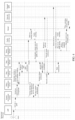
- FIG. 3 is a schematic flowchart of an embodiment of a channel switching method according to an embodiment of this application, where the method is applied to an electronic device 10, the electronic device 10 has a plurality of network channels, a first application runs on the electronic device 10, the first application is carried on a first network channel, the first application includes a plurality of packet flows, and the method includes: Step 301: In response to a monitored scenario, detect a second network channel based on a service type of the first application, and determine a path of a second network channel based on a detection result.
- the foregoing scenario may be an environment in which the first device 10 is located.
- the first device 10 is in an environment (for example, an elevator) in which a network is relatively poor.
- the first device 10 may initiate a detection request of the second network channel, so that a secondary network channel (that is, the second network channel) may be pre-stored.
- Step 302 Obtain packets of the first application on the first network channel.
- the first device 10 may obtain network information of the second network channel, where the network information may include a path of the second network channel. It can be understood that the second network channel is an available network channel, so that the first device 10 may immediately switch to the second network channel when detecting that the first network channel does not meet a service requirement, thereby reducing a switching delay.
- a packet flow of the first application may be further detected.
- Step 303 Determine a characteristic packet flow from a plurality of packet flows of the first application, collect statistics on packets in the characteristic packet flow to obtain a first statistical result, and switch the characteristic packet flow to the second network channel based on the first statistical result.
- the first device 10 may detect a packet flow of the first application in real time, and may identify the characteristic packet flow in a plurality of packet flows. Then, statistical analysis may be performed on the packets in a characteristic packet flow to obtain the first statistical result, where the first statistical result may be used to indicate whether quality of the characteristic packet flow deteriorates, that is, whether switching needs to be performed.
- the first device 10 may switch the characteristic packet flow to the second network channel.
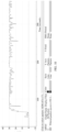
- FIG. 4 is a schematic flowchart of another embodiment of a channel switching method according to an embodiment of this application, including: Step 401: Enable a network application in response to an operation of a user.
- the user may perform an enabling operation in the electronic device 100, so as to enable a network application.
- the user may tap an icon of the network application in the electronic device 100.
- the application layer 11 in the electronic device 100 enables the network application.
- the foregoing example shows only an example of a scenario in which a network application is enabled through tapping, which does not constitute a limitation on this embodiment of this application.
- the network application may also be enabled by performing another operation (for example, double-tap, or slide).
- the foregoing network application may be a network application such as an online game, an online video, or online music.
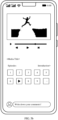
- FIG. 5a is a schematic diagram of a desktop of a mobile phone. As shown in FIG. 5a , the user may tap an icon of a video application on the desktop of the mobile phone to enable a video application. Therefore, a schematic diagram of video display shown in FIG. 5b may be obtained.
- Step 402 The environment detection component 121 detects that the network application is switched to a foreground or a network changes, and notifies the first policy management component 124.
- the environment detection component 121 at the service layer 120 in the electronic device 100 may continuously detect a status of the foregoing network application or the foregoing network environment. After detecting that any network application is switched to the foreground or the network environment changes, the environment detection component 121 may send a first notification message to the first policy management component 124, where the first notification message may be used to notify the first policy management component 124 that the network application is switched to the foreground or the network environment changes. It can be understood that the foregoing first notification message may further include an identity of the network application (for example, the identity of the network application may be a UID), and the identity may be used to uniquely identify the network application.
- an identity of the network application for example, the identity of the network application may be a UID
- the identity of the network application may be implemented by using the following code:
- Step 403 The first policy management component 124 receives the first notification message sent by the environment detection component 121, and determines whether the current network application meets a condition for enabling acceleration.
- the first policy management component 124 may determine, based on the first notification message, that the network application is switched to the foreground. Then, the first policy management component 124 may further determine whether the network application is included in a preset application whitelist.
- an application whitelist may be preset in the first policy management component 124.
- the application whitelist may include a plurality of network applications, and each network application may be identified by using the foregoing identity.
- the application whitelist may be used to represent network applications for which acceleration may be enabled.
- the network application in the preset application whitelist may include a service type.
- the network application in the preset application whitelist may be of a sensitive service, and the sensitive service may include a delay-sensitive service, a packet loss rate-sensitive service, and the like.
- the network application in the first notification message is included in the preset application whitelist, it may be determined that the network application meets an acceleration enabling condition; or if the network application in the first notification message is not included in the preset application whitelist, it may be determined that the network application does not meet the acceleration enabling condition.
- Table 1 is a network application whitelist.
- Table 1 Application name Type of characteristic flow Channel quality parameter Baidu Network Disk Download flow Rate WeChat Video flow Delay/packet loss Gaming Battle flow Delay/packet loss
- the electronic device 100 may further detect another network channel with better quality, and then the insensitive service may be directly switched to the network channel with better quality.
- Step 404 The first policy management component 124 sends a channel enable message to the second path management component 131, so as to enable a network channel.
- the first policy management component 124 may send the channel enable message to the second path management component 131, where the channel enable message is used to indicate the second path management component 131 to enable the network channel (for example, a primary network channel).
- Step 405 The second path management component 131 requests a path of the primary network channel from the first path management component 123.
- the second path management component 131 may send a primary network channel request to the first path management component 123, where the primary network channel request is used to request a path of the primary network channel.
- the primary network channel may be a primary Wi-Fi channel.
- Step 406 The first path management component 123 sends the path of the primary network channel to the second path management component 131.
- the first path management component 123 may preconfigure paths of a plurality of network channels.
- the plurality of network channels may include a primary Wi-Fi channel, a secondary Wi-Fi channel, a primary cellular channel, and a secondary cellular channel.
- the primary Wi-Fi channel and the secondary Wi-Fi channel may operate on a 2.4 GHz band or a 5 GHz band.
- the primary Wi-Fi channel operates on the 2.4 GHz band
- the secondary Wi-Fi channel operates on the 5 GHz band
- the primary Wi-Fi channel operates on the 5 GHz frequency band
- the secondary Wi-Fi channel operates on the 2.4 GHz frequency band.
- the primary cellular channel and the secondary cellular channel may be corresponding to an operator network.
- the primary cellular channel may use a SIM card 1 (the SIM card 1 belongs to a network of an operator A), and the secondary cellular channel may use a SIM card 2 (the SIM card 2 belongs to a network of an operator B).
- a priority of a primary Wi-Fi channel is higher than priorities of other three channels. Therefore, the primary network channel is usually the primary Wi-Fi channel.
- the foregoing preset channels are merely an example for description, which does not constitute a limitation on the embodiments of this application. In some embodiments, more channels may be included.
- using the primary Wi-Fi channel as the primary network channel is only a preferred solution, which does not constitute a limitation on this embodiment of this application.
- another network channel may also be selected as the primary network channel.
- the first path management component 123 may select one network channel from the plurality of network channels as the primary network channel (for example, the primary network channel is the primary Wi-Fi channel), and send the path of the primary network channel to the second path management component 131.
- Step 407 The second path management component 131 stores the received path of the primary network channel.
- the second path management component 131 may store the path of the primary network channel.
- the path of the primary network channel may be represented by "Wi-Fi1".
- FIG. 6 is a schematic diagram of an effect of using the primary network channel by a mobile phone. As shown in FIG. 6 , after the mobile phone obtains the path of the primary network channel, the primary network channel may be used to watch a video.
- a current network application may include a plurality of flows (for example, a video flow and an audio flow), and the plurality of flows may be carried on the foregoing primary network channel.
- Step 408 The first policy management component 124 sends a traffic detection request to the traffic sensing component 133.
- the traffic detection request may be used to indicate the traffic sensing component 133 to collect statistics on packets of a network application on the primary network channel.
- the traffic detection request may include an identity (for example, UID) of a current to-be-detected network application, which is used to request to detect a flow of a network application corresponding to the identity UID on the primary network channel. It can be understood that the flow of the foregoing network application may be in a form of a packet.
- step 408 may be performed at the same time as step 404, or may be performed at any moment after step 404. This is not specifically limited in this application.
- Step 409 The traffic sensing component 133 sends a traffic reporting request to the traffic reporting component 141.
- the traffic sensing component 133 may send the traffic reporting request to the traffic reporting component 141, where the traffic reporting request may be used to indicate the traffic reporting component 141 to detect packets of the network application on the current primary network channel, and report the detected packets.
- the foregoing traffic detection request may include an identity (for example, UID) of the network application.
- Step 410 The traffic reporting component 141 performs traffic detection, and reports the detected packets to the traffic sensing component 133.
- the traffic reporting component 141 may detect, based on the identity (for example, UID) of the network application in the traffic reporting request, the packets of the network application corresponding to the identity of the network application, so as to obtain the packets of the network application on the primary network channel, and may report the detected packets of the network application to the traffic sensing component 133.
- the identity for example, UID
- the traffic reporting component 141 may invoke a component (for example, a Netfilter component of an Android system) to obtain the packets of the network application on the primary network channel.
- a component for example, a Netfilter component of an Android system
- the foregoing Netfilter component is merely an example for description, which does not constitute a limitation on the embodiments of this application.
- the foregoing packet detection may also be completed by using another component.
- the foregoing network channel parameters may be implemented by using the following code:
- the detected packets may be packets in one or more characteristic flows in the current network application, and the characteristic flow may be a flow with highest sensitivity in the network application, that is, a flow that has a relatively great impact on the current network application.
- the quantity of the network channel can be evaluated by using the foregoing network channel parameters.
- Step 411 The environment detection component 121 detects a scenario in which the electronic device 100 is located.
- the scenario may be a scenario in which the user is located, that is, a scenario in which the electronic device 100 is located.
- the scenario may be that the user is in an elevator.
- the elevator scenario is merely an example for description, and the scenario may further include another scenario that causes a network change, for example, a scenario such as a high-speed railway or a garage.
- the elevator scenario is used as an example for description.
- the elevator goes up or goes down, which may cause a gravity change of the user.
- the acceleration sensor in the electronic device 100 may be used to detect the overweight and weightlessness.
- the acceleration sensor detects that the user is in a weightlessness or overweight state, that is, an acceleration of the electronic device 100 in a vertical direction is detected, it may be determined that the user is in an elevator environment.
- the environment detection component 121 may send a scenario change notification message to the first policy management component 124, where the scenario change notification message is used to notify the first policy management component 124 that the scenario in which the user is located changes (for example, the user enters the elevator), so that the first policy management component 124 can initiate detection of the secondary network channel.
- the elevator when the elevator goes up or goes down, the elevator may stop according to the needs of different users (for example, different users can click on different floors). Therefore, the elevator may continue to run or stop in a vertical direction. Because the electronic device 100 does not detect movement in a horizontal direction when the elevator goes up or goes down, it may still be determined that the electronic device 100 is in an elevator, where the movement in the horizontal direction may be detected by using the acceleration sensor in the electronic device 100. For example, if an acceleration in the horizontal direction is detected by using the foregoing acceleration sensor, the movement in the horizontal direction may be determined.
- the electronic device 100 When the electronic device 100 detects that the electronic device 100 has an acceleration in the horizontal direction, that is, when the electronic device 100 moves horizontally, it may be determined that the user is out of the elevator, that is, the electronic device 100 is out of the elevator. In this case, detection of the secondary network channel may not be performed in advance, and therefore, the scenario change notification message does not need to be sent to the first policy management component 124, thereby saving power consumption of the electronic device 100 caused by detection of the secondary network channel.
- the electronic device 100 may also determine, by detecting signal strength of a mobile network, whether the scenario in which the user is located changes. For example, when signal strength of a mobile network is weak, it may be determined that the user enters a relatively poor network environment. In this case, the electronic device 100 can determine that the scenario has changed, and may send the scenario change notification message to the first policy management component 124, so as to detect the secondary network channel in advance. When the signal strength of the mobile network becomes higher, it may be determined that the user enters a relatively good network environment. In this case, detection of the secondary network channel may not be performed in advance, and the scenario change notification message may not be sent to the first policy management component 124, thereby saving power consumption of the electronic device 100 caused by detection of the secondary network channel.
- Step 412 The environment detection component 121 sends the scenario change notification message to the first policy management component 124.
- the environment detection component 121 may send the scenario change notification message to the first policy management component 124.
- Step 413 The first policy management component 124 forwards the scenario change notification message indicating the scenario change to the second path management component 131.
- Step 414 The second path management component 131 requests the secondary network channel from the first path management component 123.
- a signal is generally poor in an elevator
- channel selection and switching are performed after the user enters the elevator
- a relatively high delay of a service may be caused, which may result in poor user experience. Therefore, when detecting that the user enters the elevator, a secondary network channel may be pre-selected. Therefore, channel switching can be accelerated, and a service delay caused by channel switching is reduced.
- the second path management component 131 may send a secondary network channel request to the first path management component 123, where the secondary network channel request may be used to request a secondary network channel.
- the foregoing secondary network channel request may further carry a label, and the label may be used to indicate that switching of the primary network channel is predicted rather than being actually performed.
- the mobile phone has four network channels: a primary Wi-Fi channel (for example, Wi-Fi1), a secondary Wi-Fi channel (for example, Wi-Fi2), a primary cellular channel (for example, Mobile1), and a secondary cellular channel (for example, Mobile2).
- a primary Wi-Fi channel for example, Wi-Fi1
- a secondary Wi-Fi channel for example, Wi-Fi2
- a primary cellular channel for example, Mobile1
- a secondary cellular channel for example, Mobile2
- the mobile phone may select a secondary network channel in advance, where the secondary network channel may be one of the foregoing secondary Wi-Fi channel (for example, Wi-Fi2), primary cellular channel (for example, Mobile1), and secondary cellular channel (for example, Mobile2) with optimal quality.
- the secondary network channel for example, Mobile1 channel
- a path of the Mobile1 channel may be stored.
- the flow A may be switched to the secondary network channel, that is, the Mobile1 channel.
- the foregoing flow B may still be carried on the primary network channel, that is, the Wi-Fi channel
- the flow A may be carried on the secondary network channel, that is, the Mobile1 channel.
- both the flow A and the flow B may be switched to the secondary network channel, that is, the Mobile1 channel.
- the Mobile1 channel As shown in FIG. 7C , in this case, both the flow A and the flow B are carried on the Mobile1 channel, and the Wi-Fi1 channel is disabled.
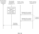
- FIG. 8a shows a process of triggering channel switching of an insensitive service.
- the traffic sensing component 133 in the mobile phone receives, within preset first duration, heartbeat flow packets detected by the traffic reporting component 141, and may determine, through statistical analysis on the heartbeat flow packets within the preset first duration, whether quality of a network channel deteriorates.
- the foregoing preset first duration may be set to be a relatively long time, for example, 5s.
- the traffic sensing component 133 may send a switching notification to the second policy management component 132 to trigger network channel switching. For example, quality of other network channels may be evaluated, and the current insensitive service may be switched to another network channel with optimal quality.
- FIG. 8b is a process of triggering channel switching of a sensitive service.
- the second path management component 131 in the mobile phone can determine that the scenario changes.
- the second path management component 131 may request a secondary network channel, so that when quality of a characteristic flow of the network application deteriorates, the second path management component 131 may switch to the secondary network channel in a timely manner, so as to save switching time and improve user experience.
- the traffic sensing component 133 in the mobile phone receives, within a preset second duration, the heartbeat flow packets detected by the traffic reporting component 141, and may determine the quality of service of the characteristic flow in the current network application through statistical analysis on the heartbeat flow packets within the preset second duration.
- the preset second duration may be equal to the preset first duration, for example, 5s, or may be shorter than the preset first duration, for example, 3s.
- the switching notification may be sent to the second policy management component 132, so as to trigger network channel switching.
- the characteristic flow of the current network application may be switched to the secondary network channel.
- Step 415 The first path management component 123 receives a secondary network channel request, and requests an enable status of each optional network channel.
- the first path management component 123 may send a channel status request to the network detection component 122, where the channel status request may be used to request to obtain an enable status of each optional network channel.
- the foregoing enable status may include an available state and an unavailable state.
- the available state may be used to represent that the optional network channel may be enabled, and the unavailable state may be used to represent that the optional network channel is disabled.
- the optional network channel may include a secondary Wi-Fi channel, a primary cellular channel, a secondary cellular channel, and the like.
- Step 416 The network detection component 122 detects an enable status of each optional network channel, and sends the enable status of each optional network channel to the first path management component 123.
- the network detection component 122 may detect the enable status of each optional network channel.
- the network detection component 122 may be configured to manage a switch of each optional network channel. When any optional network channel is enabled, the optional network channel is in an available state; and when any optional network channel is disabled, the optional network channel is in an unavailable state. Therefore, after detecting the enable status of each optional network channel requested by the first path management component 123, the network detection component 122 may send the enable status of each optional network channel to the first path management component 123.
- Step 417 The first path management component 123 requests channel quality of each available network channel.
- the first path management component 123 may select an available network channel (that is, an optional network channel in an available state), and may further send a channel evaluation request to the channel and application quality evaluation component 125, where the channel evaluation request may be used to request to evaluate quality of the available network channel.
- an available network channel that is, an optional network channel in an available state
- Step 418 The channel and application quality evaluation component 125 evaluates quality of each available network channel, and sends an evaluation result to the first path management component 123.
- the channel and application quality evaluation component 125 may evaluate the quality of each available network channel according to the channel evaluation request.
- the channel quality may include a delay, a packet loss rate, a bandwidth, a rate, and the like of the channel.
- the foregoing evaluation may be evaluating a round-trip time (Round-Trip Time, RTT) of an available network channel, and a network channel with a minimum round-trip time is optimal.
- RTT Round-Trip Time
- channel quality may be evaluated based on the foregoing RTT and the historical record, where the historical record may include a historical receiving rate, a quantity of number of historical times when the channel quality is poor, and the like.
- the channel and application quality evaluation component 125 may send the foregoing evaluation result to the first path management component 123.
- Step 419 The first path management component 123 determines a secondary network channel based on the evaluation result, and sends a path of the secondary network channel to the second path management component 131.
- the first path management component 123 may select an optimal available network channel as the secondary network channel based on the evaluation result, and may send the path of the secondary network channel to the first path management component 123.
- Step 420 The second path management component 131 receives and stores the path of the secondary network channel that is sent by the first path management component 123.
- the second path management component 131 may pre-store the path of the secondary network channel. It can be understood that, in step 411, only a scenario change is detected, that is, the current network may cause a service to be stalled, but a switching condition is not met. In this case, the electronic device 100 does not switch to the secondary network channel, that is, the electronic device 100 still uses the primary network channel.
- the second path management component 131 may pre-store the path of the secondary network channel.
- the electronic device 100 does not switch to the secondary network channel, that is, the electronic device 100 still uses the primary network channel.
- the electronic device 100 may switch the characteristic flow from the primary network channel to the secondary network channel.
- Step 421 The traffic reporting component 141 reports traffic to the traffic sensing component 133.
- the traffic reporting component 141 may continuously detect packets of the current primary network channel, and report the detected packets to the traffic sensing component 133.
- Step 422 The traffic sensing component 133 receives the packets reported by the traffic reporting component 141, analyzes the packets to obtain a packet analysis result, and sends the packet analysis result to the second policy management component 132.
- the packets may be the packets of each flow of a network application on the primary network channel.
- the traffic sensing component 133 may analyze the packets. The packet analysis may be based on characteristics of the packets, so as to identify a characteristic flow, where the characteristic flow may be a flow with highest sensitivity in a network application.
- the Game For Peace is used as an example.
- a characteristic flow of the game may be a voice flow, that is, a voice flow has a relatively great impact on the game, and has highest sensitivity. When quality of the voice flow is poor (for example, a delay and a packet loss rate do not meet a requirement), gaming experience of the user is severely affected.
- the packet analysis result may be used to indicate whether the characteristic flow meets a service requirement, for example, whether a delay requirement is met or whether a packet loss rate requirement is met.
- the packet analysis result may be sent to the second policy management component 132.
- the recognition of the voice flow packets may be implemented by collecting statistics on the heartbeat packets.
- the UDP protocol is used as an example
- characteristics of data voice flow packets may be represented by using the following characteristics:
- FIG. 9 is a schematic diagram of heartbeat packets of a voice flow in the UDP protocol.
- a preset field in the payload in the foregoing uplink and downlink packets is read, so as to identify whether the packets are voice flow packets.
- statistics of the voice flow packets may be collected, and therefore, a delay and/or a packet loss rate of the voice flow packets may be obtained.
- statistics of the voice flow packets in preset duration for example, 5s
- preset duration for example, 5s
- a delay and/or a packet loss rate of the voice flow packets do not/does not meet a requirement, it may be determined that the quality of the voice flow is poor. In this case, switching may be triggered to switch the voice flow to the secondary network channel.
- a characteristic flow of the network application is a download flow, that is, a packet of the download flow may be found in the foregoing packets, and a factor that affects the packet of the download flow may be a rate.
- the network application may further include a social network application such as WeChat.
- a characteristic flow of the network application is a video flow, that is, a packet of the video flow may be found in the foregoing packets, and a factor that affects the packet of the video flow may be a delay/or a packet loss rate.
- the characteristic flow may further include a gaming flow.
- a quantity of UDP packets can be counted periodically to determine whether the current packet flow is a battle flow.
- the UDP packets of the Game For Peace are counted based on a period of 500 ms. Therefore, a total quantity of packets in the period may be counted to determine whether the packet is a battle flow. For example, if the total quantity of packets in the period of 500 ms is greater than 10, the packet flow is a battle flow.
- FIG. 10 is a schematic diagram of packet statistics of a battle flow in the UDP protocol. As shown in FIG.
- a horizontal axis indicates a time
- a vertical axis indicates a total quantity of packets. Because almost 30 packets are kept per second, 15 packets per 500 ms may be determined through calculation. Therefore, it may be determined that the packet flow is a battle flow.
- FIG. 11 is a schematic diagram of heartbeat packets of a battle flow in the UDP protocol.
- Step 423 The second policy management component 132 determines switching based on a packet analysis result, and requests to obtain the path of the secondary network channel.
- the second policy management component 132 may determine, based on the packet analysis result, whether to perform channel switching. During specific implementation, if a characteristic flow of the current network application (for example, a voice flow in a game, a video flow in WeChat, or a download flow of the Baidu Network Disk) does not meet a requirement (for example, a delay and/or a packet loss rate), it may be determined that channel switching needs to be performed. In this case, the second policy management component 132 may send a secondary network channel path obtaining request to the second path management component 131, so as to obtain the path of the secondary network channel. For example, if the secondary network channel is a primary cell, the path of the secondary network channel may be, for example, Mobile1.
- the requesting the path of the secondary network channel may be implemented by using the following code:
- the path of the network channel (for example, the path may be represented by a device number of a network adapter or a SIM card) may be defined in a data structure.
- Example code is as follows:
- sk_bound_dev_if is a device number of a target network interface card or target SIM card to be switched. It can be understood that a packet may be received by using the foregoing network adapter or the SIM card.
- code for receiving the packet refer to the following example:
- the first device 10 may delete the path of the secondary network channel, so as to release a resource and save power consumption of the first device 10.
- the first device 10 may delete the path of the secondary network channel after preset duration (for example, preset third duration). Therefore, it can be ensured that if the quality of the characteristic flow deteriorates within the preset third duration, the first device 10 can switch to the secondary network channel in a timely manner, so as to avoid that switching cannot be performed because the path of the secondary network channel is deleted.
- the electronic device 100 may be in different environments, wireless networks are quite different. For example, when the electronic device 100 detects that the network environment in which the electronic device 100 is currently located is relatively poor, the secondary network channel may be activated. Then, when the electronic device 100 detects that the current service meets a service requirement, switching is not required (for example, the electronic device 100 enters a relatively good network environment), the electronic device 100 may continue to use the current network channel, and does not switch to the secondary network channel. Therefore, the electronic device 100 may perform only detection of the secondary network channel, for example, perform step 415 to step 420 to complete detection of the secondary network channel. Further, after completing detection of the secondary network channel, the electronic device 100 may further activate the secondary network channel.
- the activation operation may accelerate a switching procedure, thereby reducing a switching delay. That is, when detecting a current environment (for example, an elevator scenario) in which the electronic device 100 is located, the electronic device 100 may only perform detection of the secondary network channel, or may detect the secondary network channel and activate the secondary network channel. However, switching is not actually performed in the detection phase of the secondary network channel and during activation of the secondary network channel. When detecting that the current service cannot meet a service requirement, the electronic device 100 may switch the current service (for example, one or more flows of the current service) to the activated secondary network channel.
- a current environment for example, an elevator scenario
- the electronic device 100 may only perform detection of the secondary network channel, or may detect the secondary network channel and activate the secondary network channel. However, switching is not actually performed in the detection phase of the secondary network channel and during activation of the secondary network channel.
- the electronic device 100 may switch the current service (for example, one or more flows of the current service) to the activated secondary network channel.
- Step 424 The second policy management component 132 sends the path of the secondary network channel to the second path management component 131.
- Step 425 The second policy management component 132 sends a channel switching indication to the policy execution component 142.
- the second policy management component 132 may send the channel switching indication to the policy execution component 142, where the channel switching indication may be used to indicate the policy execution component 142 to switch the foregoing characteristic flow from the current primary network channel to the secondary network channel, so that channel switching is completed more quickly, thereby reducing a delay caused by channel switching and improving user experience.
- Step 426 The policy execution component 142 performs channel switching.
- the policy execution component 142 may switch the foregoing characteristic flow from the current primary network channel to the secondary network channel. That is, another flow of the foregoing network application may still be carried on the primary network channel, and the foregoing characteristic flow may be carried on the secondary network channel, so that switching can be quickly completed, thereby ensuring quality of service and user experience.
- the entire network application may be switched to the secondary network channel, that is, the primary network channel may be disabled, and all flows of the network application are carried on the secondary network channel for running.
- FIG. 12 is a schematic diagram of using a secondary network channel by a mobile phone. As shown in FIG. 12 , after the mobile phone receives the channel switching indication, the mobile phone may switch a video flow from the current primary network channel to the secondary network channel, and may use the secondary network channel to watch the video, so as to avoid freezing of the video.
- the interface connection relationship between the modules illustrated in the embodiments of this application is merely an example for description, and does not constitute a limitation on the structure of the electronic device 100.
- the electronic device 100 may alternatively use an interface connection mode that is different from those in the foregoing embodiments, or use a combination of a plurality of interface connection modes.
- the foregoing electronic device includes corresponding hardware structures and/or software modules for performing the functions.
- a person skilled in the art should easily realize that, with reference to the units and algorithm steps described in the embodiments disclosed in this specification, the embodiments of this application can be implemented in a form of hardware or hardware and computer software. Whether a function is performed by hardware or hardware driven by computer software depends on particular applications and design constraints of the technical solutions. A person skilled in the art may use different methods to implement the described functions for each particular application, but it should not be considered that the implementation goes beyond the scope of the embodiments of this application.
- each functional module may be obtained through division for a corresponding function, or two or more functions may be integrated into one processing module.
- the foregoing integrated module may be implemented in a form of hardware, or may be implemented in a form of a software functional module. It should be noted that the module division in this embodiment of this application is an example and is merely logical function division, and there may be another division manner during actual implementation.
- Functional units in the embodiments of this application may be integrated into one processing unit, or each of the units may exist alone physically, or two or more units may be integrated into one unit.
- the integrated unit may be implemented in a form of hardware, or may be implemented in a form of a software functional unit.
- the integrated unit When the integrated unit is implemented in the form of a software functional unit and sold or used as an independent product, the integrated unit may be stored in a computer readable storage medium.
- the technical solution of this embodiment of this application which is essential or a part contributing to the prior art or all or a part of the technical solution may be embodied in the form of a software product, and the computer software product is stored in a storage medium and includes several instructions for enabling a computer device (which may be a personal computer, a server or a network device) for a processor to perform all or some steps of the method according to each embodiment of this application.
- the foregoing storage medium includes any medium that can store program code, such as a flash memory, a removable hard disk, a read-only memory, a random access memory, a magnetic disk, or an optical disc.
Landscapes
- Engineering & Computer Science (AREA)
- Computer Networks & Wireless Communication (AREA)
- Signal Processing (AREA)
- Computer Security & Cryptography (AREA)
- Mobile Radio Communication Systems (AREA)
- Telephone Function (AREA)
Claims (14)
- Ein Kanalumschaltverfahren, wobei das Verfahren von einem elektronischen Gerät (100) ausgeführt wird, das elektronische Gerät (100) eine Vielzahl von Netzwerkkanälen aufweist, die drahtlose Netzwerkkanäle für die Kommunikation in einem drahtlosen Netzwerk sind, eine erste Anwendung auf dem elektronischen Gerät (100) ausgeführt wird, die erste Anwendung auf einem ersten Netzwerkkanal läuft, die erste Anwendung eine Vielzahl von Paketflüssen umfasst, und das Verfahren umfasst:als Reaktion auf die Erkennung einer überwachten Szenarioänderung Erkennen (301) eines zweiten Netzwerkkanals basierend auf einem Diensttyp der ersten Anwendung und Bestimmen und Speichern eines Pfads des zweiten Netzwerkkanals basierend auf einem Ergebnis der Erkennung, wobei das überwachte Szenario eine Umgebung ist, in der sich das elektronische Gerät (100) befindet;Erhalten (302) von Paketen der ersten Anwendung auf dem ersten Netzwerkkanal; undBestimmen (303) eines charakteristischen Paketflusses aus einer Vielzahl von Paketflüssen der ersten Anwendung, Sammeln von Statistiken über Pakete im charakteristischen Paketfluss, um ein erstes statistisches Ergebnis zu erhalten, und Umschalten des charakteristischen Paketflusses auf den zweiten Netzwerkkanal basierend auf dem ersten statistischen Ergebnis.
- Das Verfahren nach Anspruch 1, wobei die Vielzahl von Netzwerkkanälen mindestens einen primären Wi-Fi-Kanal, einen sekundären Wi-Fi-Kanal, einen primären Mobilfunkkanal und einen sekundären Mobilfunkkanal umfasst.
- Das Verfahren nach Anspruch 1, wobei der charakteristische Paketfluss mindestens einen Download-Fluss, einen Video-Fluss oder einen Gaming-Fluss umfasst.
- Das Verfahren nach einem der Ansprüche 1 bis 3, wobei die erste Anwendung eine empfindliche Anwendung ist, die eine Anwendung ist, die empfindlich auf einen Umschaltmoment reagiert, das Erhalten (302) von Paketen der ersten Anwendung auf dem ersten Netzwerkkanal umfasst:
Erhalten der Pakete der ersten Anwendung auf dem ersten Netzwerkkanal innerhalb einer voreingestellten zweiten Dauer. - Das Verfahren nach einem der Ansprüche 1 bis 4, wobei nach dem Umschalten des charakteristischen Paketflusses auf den zweiten Netzwerkkanal basierend auf dem ersten statistischen Ergebnis das Verfahren umfasst:
Tragen eines nicht charakteristischen Paketflusses der ersten Anwendung auf dem ersten Netzwerkkanal. - Das Verfahren nach einem der Ansprüche 1 bis 4, wobei nach dem Umschalten des charakteristischen Paketflusses auf den zweiten Netzwerkkanal basierend auf dem ersten statistischen Ergebnis das Verfahren umfasst:
Umschalten des nicht charakteristischen Paketflusses in der ersten Anwendung auf den zweiten Netzwerkkanal und Deaktivieren des ersten Netzwerkkanals. - Das Verfahren gemäß einem der Ansprüche 1 bis 6, wobei das Verfahren weiterhin umfasst:
Löschen des Pfads des zweiten Netzwerkkanals basierend auf dem ersten statistischen Ergebnis. - Das Verfahren gemäß Anspruch 7, wobei das Löschen des Pfads des zweiten Netzwerkkanals basierend auf dem ersten statistischen Ergebnis umfasst:
Löschen des Pfads des zweiten Netzwerkkanals nach einer voreingestellten vierten Dauer basierend auf dem ersten statistischen Ergebnis. - Das Verfahren gemäß einem der Ansprüche 4 bis 8, wobei das Erkennen (301) eines zweiten Netzwerkkanals basierend auf einem Diensttyp der ersten Anwendung und das Bestimmen und Speichern eines Pfads des zweiten Netzwerkkanals basierend auf einem Ergebnis der Erkennung umfasst:Erkennen einer Rundreiseverzögerung eines Pakets des zweiten Netzwerkkanals basierend auf dem Diensttyp der ersten Anwendung, um ein Ergebnis der Erkennung zu erhalten, wobei das Ergebnis der Erkennung die Rundreiseverzögerung eines Pakets jedes der mehreren Netzwerkkanäle umfasst; undBestimmen des Pfads des zweiten Netzwerkkanals basierend auf dem Ergebnis der Erkennung;Das Ergebnis der Erkennung umfasst weiterhin einen historischen Datensatz jedes Netzwerkkanals.
- Das Verfahren gemäß einem der Ansprüche 1 bis 9, wobei das Sammeln von Statistiken über Pakete im charakteristischen Paketfluss, um ein erstes statistisches Ergebnis zu erhalten, umfasst:
Sammeln von Statistiken über eine Verzögerung oder eine Paketverlustrate der Pakete im charakteristischen Paketfluss, um das erste statistische Ergebnis zu erhalten, wobei das erste statistische Ergebnis verwendet wird, um anzuzeigen, ob der charakteristische Paketfluss eine voreingestellte Verzögerungsanforderung oder eine voreingestellte Paketverlustrateanforderung erfüllt. - Das Verfahren gemäß einem der Ansprüche 1 bis 10, wobei die elektronische Vorrichtung (100) weiterhin einen Beschleunigungssensor (180E) umfasst, und das Szenario durch Erkennung durch den Beschleunigungssensor (180E) erhalten wird.
- Das Verfahren gemäß Anspruch 11, wobei das Szenario durch Erkennung der Bewegung der elektronischen Vorrichtung (100) in vertikaler Richtung durch den Beschleunigungssensor (180E) erhalten wird.
- Eine elektronische Vorrichtung (100), umfassend: einen Speicher (121), wobei der Speicher (121) konfiguriert ist, Computerprogrammcodes zu speichern, der Computerprogrammcodes umfasst eine Anweisung, und wenn die elektronische Vorrichtung (100) die Anweisung aus dem Speicher (121) liest, wird die elektronische Vorrichtung (100) befähigt, das Verfahren gemäß einem der Ansprüche 1 bis 12 auszuführen.
- Ein computerlesbares Speichermedium, wobei das computerlesbare Speichermedium eine Anweisung umfasst und wenn die Anweisung auf einem elektronischen Gerät (100) ausgeführt wird, das elektronische Gerät (100) in die Lage versetzt wird, das Verfahren gemäß einem der Ansprüche 1 bis 12 auszuführen.
Applications Claiming Priority (2)
| Application Number | Priority Date | Filing Date | Title |
|---|---|---|---|
| CN202110729329.1A CN113810938B (zh) | 2021-06-29 | 2021-06-29 | 通道切换方法、电子设备及存储介质 |
| PCT/CN2022/072713 WO2023273317A1 (zh) | 2021-06-29 | 2022-01-19 | 通道切换方法、电子设备及存储介质 |
Publications (3)
| Publication Number | Publication Date |
|---|---|
| EP4236434A1 EP4236434A1 (de) | 2023-08-30 |
| EP4236434A4 EP4236434A4 (de) | 2024-05-22 |
| EP4236434B1 true EP4236434B1 (de) | 2025-04-30 |
Family
ID=78893131
Family Applications (1)
| Application Number | Title | Priority Date | Filing Date |
|---|---|---|---|
| EP22831151.0A Active EP4236434B1 (de) | 2021-06-29 | 2022-01-19 | Kanalumschaltverfahren, elektronische vorrichtung und speichermedium |
Country Status (4)
| Country | Link |
|---|---|
| US (1) | US20240089822A1 (de) |
| EP (1) | EP4236434B1 (de) |
| CN (2) | CN113810938B (de) |
| WO (1) | WO2023273317A1 (de) |
Families Citing this family (6)
| Publication number | Priority date | Publication date | Assignee | Title |
|---|---|---|---|---|
| CN113810938B (zh) * | 2021-06-29 | 2022-09-27 | 荣耀终端有限公司 | 通道切换方法、电子设备及存储介质 |
| CN114268936B (zh) * | 2022-03-01 | 2022-07-12 | 荣耀终端有限公司 | 数据传输方法及装置 |
| CN114679443A (zh) * | 2022-03-03 | 2022-06-28 | 北京百度网讯科技有限公司 | 一种下载视频数据的方法、装置、电子设备及存储介质 |
| CN114710814B (zh) * | 2022-03-16 | 2024-12-17 | 达闼机器人股份有限公司 | 终端设备的控制方法、装置、系统、存储介质及电子设备 |
| CN116709367B (zh) * | 2022-10-17 | 2024-07-12 | 荣耀终端有限公司 | 一种网络加速方法和装置 |
| CN115563543B (zh) * | 2022-10-28 | 2024-03-29 | 国网江苏省电力有限公司无锡供电分公司 | 基于通道质量多端电气量保护原理选取方法、装置及系统 |
Family Cites Families (89)
| Publication number | Priority date | Publication date | Assignee | Title |
|---|---|---|---|---|
| FI110658B (fi) * | 1998-01-15 | 2003-02-28 | Nokia Corp | Parannettu paikannusgeometria ja solupohjainen paikannusjärjestelmä |
| US6453687B2 (en) * | 2000-01-07 | 2002-09-24 | Robertshaw Controls Company | Refrigeration monitor unit |
| US6944158B1 (en) * | 2000-02-18 | 2005-09-13 | Alcatel | Flow integrity for path transitioning data switch |
| DE60134346D1 (de) * | 2001-05-15 | 2008-07-17 | Nokia Corp | Verfahren zur kanalzuweisung zu einem mobilen endgerät das sich in einem zellularen kommunikationsnetz bewegt |
| US7010301B2 (en) * | 2001-06-28 | 2006-03-07 | Lucent Technologies Inc. | Apparatus, method and system for mobile wireless communication hand-off utilizing ISDN multiway capabilities |
| SE0104325D0 (sv) * | 2001-12-20 | 2001-12-20 | Ericsson Telefon Ab L M | A method and apparatus for switching access between mobile networks |
| US20050185630A1 (en) * | 2002-11-07 | 2005-08-25 | Nobuhisa Aoki | Mobile communication system |
| KR100705579B1 (ko) * | 2005-08-01 | 2007-04-10 | 삼성전자주식회사 | 복합망을 이용한 핸드오프 구현 시스템 및 그 방법 |
| US20070165574A1 (en) * | 2006-01-13 | 2007-07-19 | Motorola, Inc. | Method and apparatus to minimize packet loss during active data hard handoff |
| CN101155124B (zh) * | 2006-09-27 | 2011-09-14 | 华为技术有限公司 | 一种实现组播快速重路由的方法 |
| CN101094175B (zh) * | 2007-06-14 | 2011-06-01 | 华为技术有限公司 | 一种组播流量保护方法、装置及系统 |
| CN101119314B (zh) * | 2007-09-14 | 2010-06-23 | 中国科学院计算技术研究所 | 一种多模终端业务流的控制系统和装置以及方法 |
| WO2010041440A1 (ja) * | 2008-10-08 | 2010-04-15 | パナソニック株式会社 | インタフェース切換システム、モバイルノード、代理ノード及び移動管理ノード |
| US9104986B2 (en) * | 2009-03-09 | 2015-08-11 | Centurylink Intellectual Property Llc | Customer premise equipment with access to free market based pricing for bandwidth on a communications network |
| WO2011019925A2 (en) * | 2009-08-12 | 2011-02-17 | Nortel Networks Limited | Providing a deny response that specifies a delay time |
| US8346274B2 (en) * | 2010-05-21 | 2013-01-01 | Apple Inc. | Method to control multiple radio access bearers in a wireless device |
| EP2584839B1 (de) * | 2010-06-17 | 2019-06-26 | Nec Corporation | Pfadsteuerungsvorrichtung und pfadsteuerungsverfahren |
| US20120311173A1 (en) * | 2011-05-31 | 2012-12-06 | Broadcom Corporation | Dynamic Wireless Channel Selection And Protocol Control For Streaming Media |
| US8811187B2 (en) * | 2011-08-17 | 2014-08-19 | Verizon Patent And Licensing Inc. | Radio access network technology optimization based on application type |
| WO2013044967A1 (en) * | 2011-09-29 | 2013-04-04 | Telefonaktiebolaget L M Ericsson (Publ) | Adding new alternative paths for restoration in wson network |
| JP2013078065A (ja) * | 2011-09-30 | 2013-04-25 | Fujitsu Mobile Communications Ltd | 無線通信端末及び無線通信方法 |
| CN102448150A (zh) * | 2011-12-30 | 2012-05-09 | 上海顶竹通讯技术有限公司 | 多模终端的业务处理系统及方法 |
| EP2621135B1 (de) * | 2012-01-24 | 2018-06-13 | ADVA Optical Networking SE | Verfahren und System zur Bereitstellung eines flexiblen Sekundärdatenpfades |
| US9585184B1 (en) * | 2012-10-29 | 2017-02-28 | Google Inc. | Using multiple wireless connections |
| US9203699B2 (en) * | 2014-02-11 | 2015-12-01 | Lenovo Enterprise Solutions (Singapore) Pte. Ltd. | Constructing and verifying switch fabric cabling schemes |
| US9678840B2 (en) * | 2014-04-29 | 2017-06-13 | Cisco Technology, Inc. | Fast failover for application performance based WAN path optimization with multiple border routers |
| KR102126994B1 (ko) * | 2014-06-17 | 2020-06-25 | 삼성전자주식회사 | 채널 선택을 위한 방법 및 그 전자 장치 |
| KR101746191B1 (ko) * | 2014-06-27 | 2017-06-12 | 주식회사 케이티 | 다중 경로 통신을 위한 네트워크 장치 및 단말, 이들의 동작 방법, 그리고 동작 방법을 구현한 프로그램 |
| US9893995B1 (en) * | 2014-09-25 | 2018-02-13 | Cisco Technology, Inc. | Systems, methods, and apparatus for implementing agents in service appliances |
| US20160094462A1 (en) * | 2014-09-26 | 2016-03-31 | Telefonaktiebolaget L M Ericsson (Publ) | Method and apparatus for dynamically adjusting retransmission timing in a transport layer |
| US20160112941A1 (en) * | 2014-10-21 | 2016-04-21 | Microsoft Corporation | Connection selection in hybrid networks |
| US9210625B1 (en) * | 2015-04-24 | 2015-12-08 | Amazon Technologies, Inc. | Systems and methods for managing network connections |
| US10122801B2 (en) * | 2015-07-02 | 2018-11-06 | Qualcomm Incorporated | Service discovery and topology management |
| US10242556B2 (en) * | 2015-10-21 | 2019-03-26 | Mutualink, Inc. | Wearable smart router |
| US20170156083A1 (en) * | 2015-11-30 | 2017-06-01 | Zynga Inc. | Maintaining persistent mobile device session |
| US20180338268A1 (en) * | 2015-12-01 | 2018-11-22 | Lg Electronics Inc. | Method and apparatus for performing application category based traffic steering in wireless communication system |
| WO2017112820A1 (en) * | 2015-12-22 | 2017-06-29 | Rapidsos, Inc. | Systems and methods for robust and persistent emergency communications |
| US20170214626A1 (en) * | 2016-01-25 | 2017-07-27 | Rivet Networks Llc | Application based link selection based on link characteristics |
| CN105786618B (zh) * | 2016-02-24 | 2019-06-18 | 华为技术有限公司 | 加速器网络中路由报文的方法和装置 |
| US10024671B2 (en) * | 2016-11-16 | 2018-07-17 | Allstate Insurance Company | Multi-stop route selection system |
| US10749970B1 (en) * | 2016-12-28 | 2020-08-18 | Wells Fargo Bank, N.A. | Continuous task-based communication sessions |
| US10575128B2 (en) * | 2017-02-20 | 2020-02-25 | JVC Kenwood Corporation | Management device, management method, and terminal device for displaying additional information on image and displaying image |
| WO2018171460A1 (en) * | 2017-03-24 | 2018-09-27 | Telefonaktiebolaget Lm Ericsson (Publ) | Method and apparatus for determining a modulation scheme in direct link-based communication |
| CN107612825B (zh) * | 2017-08-04 | 2020-10-27 | 华为技术有限公司 | 建立灵活以太网路径的方法和网络设备 |
| LT3761613T (lt) * | 2017-08-28 | 2023-03-10 | Bright Data Ltd. | Būdas pagerinti turinio parsisiuntimą, pasirenkant tunelinius įrenginius |
| CN111247079B (zh) * | 2017-10-26 | 2021-06-22 | 三菱电机株式会社 | 监视装置以及监视系统 |
| JP2019083459A (ja) * | 2017-10-31 | 2019-05-30 | 日本電気株式会社 | 通信装置、制御方法およびプログラム |
| CN111527767B (zh) * | 2017-12-27 | 2023-10-20 | 华为技术有限公司 | 一种网络性能提升的方法及设备 |
| CN111183403B (zh) * | 2018-02-22 | 2024-04-26 | 深圳市大疆创新科技有限公司 | 监视方法和设备 |
| CN110248376B (zh) * | 2018-03-08 | 2022-05-24 | 华为技术有限公司 | 一种链路维护的方法及装置 |
| US10986219B2 (en) * | 2018-06-19 | 2021-04-20 | At&T Intellectual Property I, L.P. | LTE fault-tolerant signaling approach |
| US10602551B2 (en) * | 2018-06-27 | 2020-03-24 | Charter Communications Operating, Llc | Methods and apparatus for testing alternative wireless connections and selecting a wireless connection |
| US11627587B2 (en) * | 2018-07-23 | 2023-04-11 | Magic Leap, Inc. | Coexistence interference avoidance between two different radios operating in the same band |
| EP3827611A4 (de) * | 2018-07-26 | 2021-08-04 | Razer (Asia-Pacific) Pte Ltd. | Intelligenter adaptiver kanalumschaltender spielrouter |
| FR3084549B1 (fr) * | 2018-07-30 | 2022-02-18 | Ingenico Group | Procede de transmission de donnees vers deux passerelles distinctes, et dispositif correspondant. |
| CN110972177B (zh) * | 2018-09-28 | 2022-10-11 | 华为技术有限公司 | 一种链路检测方法及装置 |
| US12041486B2 (en) * | 2018-10-11 | 2024-07-16 | Nokia Technologies Oy | Active mode traffic steering and switching between cellular and non-cellular systems |
| WO2020077517A1 (zh) * | 2018-10-16 | 2020-04-23 | 华为技术有限公司 | 一种高速移动场景下的小区切换方法及装置 |
| US10813009B2 (en) * | 2018-12-04 | 2020-10-20 | T-Mobile Usa, Inc. | Changing radio access technologies to connect to a network |
| US11445422B2 (en) * | 2018-12-13 | 2022-09-13 | At&T Intellectual Property I, L.P. | Adaptable network communications |
| KR102775191B1 (ko) * | 2019-02-15 | 2025-03-05 | 삼성전자주식회사 | 무선 네트워크 환경에서 핸드오버를 수행하기 위한 전자 장치 및 그에 관한 방법 |
| US11452014B2 (en) * | 2019-03-08 | 2022-09-20 | Meta Platforms Technologies, Llc | Secondary link for AR/VR applications |
| CN110072263B (zh) * | 2019-03-26 | 2021-08-03 | 华为技术有限公司 | 一种切换上网卡的方法和电子设备 |
| EP3723444A1 (de) * | 2019-04-12 | 2020-10-14 | Samsung Electronics Co., Ltd. | Elektronische vorrichtung mit unterstützung von doppelter konnektivität und verfahren zum betrieb davon |
| US20220210833A1 (en) * | 2019-04-30 | 2022-06-30 | Nokia Technologies Oy | Channel detection before transmission |
| US12001319B2 (en) * | 2019-07-10 | 2024-06-04 | Micro Focus Llc | Device debugging connection control and maintenance |
| US11245742B2 (en) * | 2019-07-19 | 2022-02-08 | Juniper Networks, Inc | Apparatus, system, and method for flow-level switchover of video streams |
| US12579897B2 (en) * | 2019-07-26 | 2026-03-17 | Telefonaktiebolaget Lm Ericsson (Publ) | Mobile device and methods for travelling towards a destination using a communication network |
| CN110505601A (zh) * | 2019-07-30 | 2019-11-26 | 大连理工大学 | 一种车联网中基于车辆行驶态势场模型的信息发送频率优化方法 |
| US10880356B1 (en) * | 2019-08-05 | 2020-12-29 | Amazon Technologies, Inc. | Techniques for switching communication channels |
| CN114175828B (zh) * | 2019-08-16 | 2024-06-14 | 华为技术有限公司 | 确定信道的方法和装置 |
| CN112738745B (zh) * | 2019-10-14 | 2023-07-04 | Oppo广东移动通信有限公司 | 控制网络连接的方法及相关产品 |
| CN113037624A (zh) * | 2019-12-25 | 2021-06-25 | 华为技术有限公司 | 一种数据流控制的方法和装置 |
| CN116866872A (zh) * | 2020-01-09 | 2023-10-10 | 博泰车联网科技(上海)股份有限公司 | 用于信息处理的方法、设备和计算机存储介质 |
| US10939367B1 (en) * | 2020-01-28 | 2021-03-02 | Dell Products, L.P. | Predictive scanning and handover |
| CN111355732B (zh) * | 2020-02-28 | 2021-06-11 | 腾讯科技(深圳)有限公司 | 链接检测方法、装置、电子设备及存储介质 |
| KR102894604B1 (ko) * | 2020-03-03 | 2025-12-03 | 삼성전자주식회사 | 복수의 통신 방식들을 이용하는 전자 장치 및 그 제어 방법 |
| US11743709B2 (en) * | 2020-04-08 | 2023-08-29 | Qualcomm Incorporated | Context updates for multi-link devices |
| CN115428411B (zh) * | 2020-04-23 | 2024-05-28 | 瞻博网络公司 | 使用会话建立度量的会话监测 |
| US11412511B2 (en) * | 2020-05-05 | 2022-08-09 | Facebook Technologies, Llc | Switching between different communication protocols |
| WO2022000264A1 (zh) * | 2020-06-30 | 2022-01-06 | 新华三技术有限公司 | 故障检测方法、装置及pe设备 |
| US11582068B2 (en) * | 2020-07-24 | 2023-02-14 | Cisco Technology, Inc. | Scalable mechanism for optimized application performance in SD-WAN |
| US11637886B2 (en) * | 2020-09-25 | 2023-04-25 | Apple Inc. | Cellular communication protocol aware multimedia streaming |
| CN112217679B (zh) * | 2020-10-16 | 2024-05-31 | 腾讯科技(深圳)有限公司 | 应用程序加速方法、装置、计算机设备和存储介质 |
| US11750497B2 (en) * | 2021-01-14 | 2023-09-05 | Ciena Corporation | BGP route aggregation exception systems and methods |
| US11463365B1 (en) * | 2021-01-15 | 2022-10-04 | Cisco Technology, Inc. | Preempting time-based SLA violations in computer networks |
| US11720835B2 (en) * | 2021-02-25 | 2023-08-08 | Avaya Management L.P. | Context based channel switchover |
| US20220394439A1 (en) * | 2021-06-08 | 2022-12-08 | Arlo Technologies, Inc | Electronic Monitoring System with Secondary Communication Path for Evaluating Device Locations |
| CN113810938B (zh) * | 2021-06-29 | 2022-09-27 | 荣耀终端有限公司 | 通道切换方法、电子设备及存储介质 |
-
2021
- 2021-06-29 CN CN202110729329.1A patent/CN113810938B/zh active Active
-
2022
- 2022-01-19 EP EP22831151.0A patent/EP4236434B1/de active Active
- 2022-01-19 US US18/037,978 patent/US20240089822A1/en active Pending
- 2022-01-19 CN CN202280036454.7A patent/CN117337588A/zh active Pending
- 2022-01-19 WO PCT/CN2022/072713 patent/WO2023273317A1/zh not_active Ceased
Also Published As
| Publication number | Publication date |
|---|---|
| CN117337588A (zh) | 2024-01-02 |
| CN113810938B (zh) | 2022-09-27 |
| WO2023273317A1 (zh) | 2023-01-05 |
| EP4236434A4 (de) | 2024-05-22 |
| CN113810938A (zh) | 2021-12-17 |
| US20240089822A1 (en) | 2024-03-14 |
| EP4236434A1 (de) | 2023-08-30 |
Similar Documents
| Publication | Publication Date | Title |
|---|---|---|
| US11736224B2 (en) | Data transmission method and electronic device | |
| EP4236434A1 (de) | Kanalumschaltverfahren, elektronische vorrichtung und speichermedium | |
| CN112954749B (zh) | 一种网络切换方法及电子设备 | |
| EP4135405B1 (de) | Kanalumschaltverfahren, elektronische vorrichtung und speichermedium | |
| CN113316199B (zh) | 一种连接管理方法及相关设备 | |
| EP4216501B1 (de) | Verfahren zum umschalten von kanälen, elektronische vorrichtung und speichermedium | |
| CN115696483B (zh) | 基于电子设备状态的网络链路切换方法和电子设备 | |
| CN113490291B (zh) | 数据下载方法、装置和终端设备 | |
| WO2021190314A1 (zh) | 触控屏的滑动响应控制方法及装置、电子设备 | |
| US12177710B2 (en) | Device control method and system, and related apparatus | |
| JP2022515446A (ja) | 接続確立方法および端末デバイス | |
| CN115484649B (zh) | 通道切换方法、电子设备及存储介质 | |
| CN113243126B (zh) | 一种用于终端的网络管理方法和终端 | |
| EP4195836B1 (de) | Verfahren und vorrichtung zur bestimmung des minimalen schlitzversatzwerts | |
| CN113596919B (zh) | 数据下载方法、装置和终端设备 | |
| CN113810965B (zh) | 通道切换方法、电子设备及存储介质 | |
| US12512897B2 (en) | Antenna switching method and terminal device | |
| CN116321265B (zh) | 网络质量评估方法、电子设备以及存储介质 | |
| RU2811567C1 (ru) | Способ переключения каналов, электронное устройство и носитель данных | |
| CN117354876A (zh) | 一种数据迁移方法、电子设备和组网系统 | |
| CN116708317B (zh) | 数据包mtu的调整方法、装置和终端设备 | |
| US12635014B2 (en) | Bluetooth communication method, terminal device, and computer-readable storage medium | |
| US20230189366A1 (en) | Bluetooth Communication Method, Terminal Device, and Computer-Readable Storage Medium | |
| HK40068161B (en) | Channel switching method, electronic device and storage medium | |
| WO2024239717A1 (zh) | 服务推送方法、电子设备、系统及存储介质 |
Legal Events
| Date | Code | Title | Description |
|---|---|---|---|
| STAA | Information on the status of an ep patent application or granted ep patent |
Free format text: STATUS: THE INTERNATIONAL PUBLICATION HAS BEEN MADE |
|
| PUAI | Public reference made under article 153(3) epc to a published international application that has entered the european phase |
Free format text: ORIGINAL CODE: 0009012 |
|
| STAA | Information on the status of an ep patent application or granted ep patent |
Free format text: STATUS: REQUEST FOR EXAMINATION WAS MADE |
|
| 17P | Request for examination filed |
Effective date: 20230522 |
|
| AK | Designated contracting states |
Kind code of ref document: A1 Designated state(s): AL AT BE BG CH CY CZ DE DK EE ES FI FR GB GR HR HU IE IS IT LI LT LU LV MC MK MT NL NO PL PT RO RS SE SI SK SM TR |
|
| REG | Reference to a national code |
Ref country code: DE Free format text: PREVIOUS MAIN CLASS: H04W0024040000 Ref country code: DE Ref legal event code: R079 Ref document number: 602022014022 Country of ref document: DE Free format text: PREVIOUS MAIN CLASS: H04W0024040000 Ipc: H04W0036300000 |
|
| A4 | Supplementary search report drawn up and despatched |
Effective date: 20240423 |
|
| RIC1 | Information provided on ipc code assigned before grant |
Ipc: H04W 36/36 20090101ALN20240417BHEP Ipc: H04W 84/12 20090101ALN20240417BHEP Ipc: H04W 36/04 20090101ALN20240417BHEP Ipc: H04W 36/00 20090101ALN20240417BHEP Ipc: H04W 4/02 20180101ALI20240417BHEP Ipc: H04W 12/088 20210101ALI20240417BHEP Ipc: H04W 36/30 20090101AFI20240417BHEP |
|
| DAV | Request for validation of the european patent (deleted) | ||
| DAX | Request for extension of the european patent (deleted) | ||
| GRAP | Despatch of communication of intention to grant a patent |
Free format text: ORIGINAL CODE: EPIDOSNIGR1 |
|
| STAA | Information on the status of an ep patent application or granted ep patent |
Free format text: STATUS: GRANT OF PATENT IS INTENDED |
|
| RIC1 | Information provided on ipc code assigned before grant |
Ipc: H04W 36/36 20090101ALN20241112BHEP Ipc: H04W 84/12 20090101ALN20241112BHEP Ipc: H04W 36/04 20090101ALN20241112BHEP Ipc: H04W 36/00 20090101ALN20241112BHEP Ipc: H04W 4/02 20180101ALI20241112BHEP Ipc: H04W 12/088 20210101ALI20241112BHEP Ipc: H04W 36/30 20090101AFI20241112BHEP |
|
| INTG | Intention to grant announced |
Effective date: 20241127 |
|
| GRAS | Grant fee paid |
Free format text: ORIGINAL CODE: EPIDOSNIGR3 |
|
| GRAA | (expected) grant |
Free format text: ORIGINAL CODE: 0009210 |
|
| STAA | Information on the status of an ep patent application or granted ep patent |
Free format text: STATUS: THE PATENT HAS BEEN GRANTED |
|
| AK | Designated contracting states |
Kind code of ref document: B1 Designated state(s): AL AT BE BG CH CY CZ DE DK EE ES FI FR GB GR HR HU IE IS IT LI LT LU LV MC MK MT NL NO PL PT RO RS SE SI SK SM TR |
|
| REG | Reference to a national code |
Ref country code: CH Ref legal event code: EP Ref country code: GB Ref legal event code: FG4D |
|
| REG | Reference to a national code |
Ref country code: DE Ref legal event code: R096 Ref document number: 602022014022 Country of ref document: DE |
|
| REG | Reference to a national code |
Ref country code: IE Ref legal event code: FG4D |
|
| REG | Reference to a national code |
Ref country code: NL Ref legal event code: FP |
|
| REG | Reference to a national code |
Ref country code: AT Ref legal event code: MK05 Ref document number: 1791258 Country of ref document: AT Kind code of ref document: T Effective date: 20250430 |
|
| PG25 | Lapsed in a contracting state [announced via postgrant information from national office to epo] |
Ref country code: FI Free format text: LAPSE BECAUSE OF FAILURE TO SUBMIT A TRANSLATION OF THE DESCRIPTION OR TO PAY THE FEE WITHIN THE PRESCRIBED TIME-LIMIT Effective date: 20250430 Ref country code: PT Free format text: LAPSE BECAUSE OF FAILURE TO SUBMIT A TRANSLATION OF THE DESCRIPTION OR TO PAY THE FEE WITHIN THE PRESCRIBED TIME-LIMIT Effective date: 20250901 Ref country code: ES Free format text: LAPSE BECAUSE OF FAILURE TO SUBMIT A TRANSLATION OF THE DESCRIPTION OR TO PAY THE FEE WITHIN THE PRESCRIBED TIME-LIMIT Effective date: 20250430 |
|
| REG | Reference to a national code |
Ref country code: LT Ref legal event code: MG9D |
|
| PG25 | Lapsed in a contracting state [announced via postgrant information from national office to epo] |
Ref country code: NO Free format text: LAPSE BECAUSE OF FAILURE TO SUBMIT A TRANSLATION OF THE DESCRIPTION OR TO PAY THE FEE WITHIN THE PRESCRIBED TIME-LIMIT Effective date: 20250730 Ref country code: GR Free format text: LAPSE BECAUSE OF FAILURE TO SUBMIT A TRANSLATION OF THE DESCRIPTION OR TO PAY THE FEE WITHIN THE PRESCRIBED TIME-LIMIT Effective date: 20250731 |
|
| PG25 | Lapsed in a contracting state [announced via postgrant information from national office to epo] |
Ref country code: PL Free format text: LAPSE BECAUSE OF FAILURE TO SUBMIT A TRANSLATION OF THE DESCRIPTION OR TO PAY THE FEE WITHIN THE PRESCRIBED TIME-LIMIT Effective date: 20250430 |
|
| PG25 | Lapsed in a contracting state [announced via postgrant information from national office to epo] |
Ref country code: BG Free format text: LAPSE BECAUSE OF FAILURE TO SUBMIT A TRANSLATION OF THE DESCRIPTION OR TO PAY THE FEE WITHIN THE PRESCRIBED TIME-LIMIT Effective date: 20250430 |
|
| PG25 | Lapsed in a contracting state [announced via postgrant information from national office to epo] |
Ref country code: HR Free format text: LAPSE BECAUSE OF FAILURE TO SUBMIT A TRANSLATION OF THE DESCRIPTION OR TO PAY THE FEE WITHIN THE PRESCRIBED TIME-LIMIT Effective date: 20250430 |
|
| PG25 | Lapsed in a contracting state [announced via postgrant information from national office to epo] |
Ref country code: AT Free format text: LAPSE BECAUSE OF FAILURE TO SUBMIT A TRANSLATION OF THE DESCRIPTION OR TO PAY THE FEE WITHIN THE PRESCRIBED TIME-LIMIT Effective date: 20250430 |
|
| PG25 | Lapsed in a contracting state [announced via postgrant information from national office to epo] |
Ref country code: RS Free format text: LAPSE BECAUSE OF FAILURE TO SUBMIT A TRANSLATION OF THE DESCRIPTION OR TO PAY THE FEE WITHIN THE PRESCRIBED TIME-LIMIT Effective date: 20250731 |
|
| PG25 | Lapsed in a contracting state [announced via postgrant information from national office to epo] |
Ref country code: IS Free format text: LAPSE BECAUSE OF FAILURE TO SUBMIT A TRANSLATION OF THE DESCRIPTION OR TO PAY THE FEE WITHIN THE PRESCRIBED TIME-LIMIT Effective date: 20250830 |
|
| PG25 | Lapsed in a contracting state [announced via postgrant information from national office to epo] |
Ref country code: LV Free format text: LAPSE BECAUSE OF FAILURE TO SUBMIT A TRANSLATION OF THE DESCRIPTION OR TO PAY THE FEE WITHIN THE PRESCRIBED TIME-LIMIT Effective date: 20250430 |
|
| PGFP | Annual fee paid to national office [announced via postgrant information from national office to epo] |
Ref country code: GB Payment date: 20251204 Year of fee payment: 5 |
|
| PG25 | Lapsed in a contracting state [announced via postgrant information from national office to epo] |
Ref country code: DK Free format text: LAPSE BECAUSE OF FAILURE TO SUBMIT A TRANSLATION OF THE DESCRIPTION OR TO PAY THE FEE WITHIN THE PRESCRIBED TIME-LIMIT Effective date: 20250430 Ref country code: SM Free format text: LAPSE BECAUSE OF FAILURE TO SUBMIT A TRANSLATION OF THE DESCRIPTION OR TO PAY THE FEE WITHIN THE PRESCRIBED TIME-LIMIT Effective date: 20250430 |
|
| PGFP | Annual fee paid to national office [announced via postgrant information from national office to epo] |
Ref country code: NL Payment date: 20251215 Year of fee payment: 5 |
|
| PG25 | Lapsed in a contracting state [announced via postgrant information from national office to epo] |
Ref country code: CZ Free format text: LAPSE BECAUSE OF FAILURE TO SUBMIT A TRANSLATION OF THE DESCRIPTION OR TO PAY THE FEE WITHIN THE PRESCRIBED TIME-LIMIT Effective date: 20250430 |
|
| PG25 | Lapsed in a contracting state [announced via postgrant information from national office to epo] |
Ref country code: EE Free format text: LAPSE BECAUSE OF FAILURE TO SUBMIT A TRANSLATION OF THE DESCRIPTION OR TO PAY THE FEE WITHIN THE PRESCRIBED TIME-LIMIT Effective date: 20250430 |
|
| PG25 | Lapsed in a contracting state [announced via postgrant information from national office to epo] |
Ref country code: SK Free format text: LAPSE BECAUSE OF FAILURE TO SUBMIT A TRANSLATION OF THE DESCRIPTION OR TO PAY THE FEE WITHIN THE PRESCRIBED TIME-LIMIT Effective date: 20250430 |
|
| PG25 | Lapsed in a contracting state [announced via postgrant information from national office to epo] |
Ref country code: IT Free format text: LAPSE BECAUSE OF FAILURE TO SUBMIT A TRANSLATION OF THE DESCRIPTION OR TO PAY THE FEE WITHIN THE PRESCRIBED TIME-LIMIT Effective date: 20250430 |
|
| REG | Reference to a national code |
Ref country code: DE Ref legal event code: R097 Ref document number: 602022014022 Country of ref document: DE |
|
| PLBE | No opposition filed within time limit |
Free format text: ORIGINAL CODE: 0009261 |
|
| STAA | Information on the status of an ep patent application or granted ep patent |
Free format text: STATUS: NO OPPOSITION FILED WITHIN TIME LIMIT |
|
| REG | Reference to a national code |
Ref country code: CH Ref legal event code: L10 Free format text: ST27 STATUS EVENT CODE: U-0-0-L10-L00 (AS PROVIDED BY THE NATIONAL OFFICE) Effective date: 20260311 |
|
| 26N | No opposition filed |
Effective date: 20260202 |
|
| PGFP | Annual fee paid to national office [announced via postgrant information from national office to epo] |
Ref country code: DE Payment date: 20251203 Year of fee payment: 5 |