EP4236470A1 - Verfahren und vorrichtung zum multiplexen einer relaisverbindung, relaisvorrichtung, kommunikationsvorrichtungen und medium - Google Patents
Verfahren und vorrichtung zum multiplexen einer relaisverbindung, relaisvorrichtung, kommunikationsvorrichtungen und medium Download PDFInfo
- Publication number
- EP4236470A1 EP4236470A1 EP21881962.1A EP21881962A EP4236470A1 EP 4236470 A1 EP4236470 A1 EP 4236470A1 EP 21881962 A EP21881962 A EP 21881962A EP 4236470 A1 EP4236470 A1 EP 4236470A1
- Authority
- EP
- European Patent Office
- Prior art keywords
- communication
- sidelink
- communication device
- multiplexing
- relay
- Prior art date
- Legal status (The legal status is an assumption and is not a legal conclusion. Google has not performed a legal analysis and makes no representation as to the accuracy of the status listed.)
- Pending
Links
Images





Classifications
-
- H—ELECTRICITY
- H04—ELECTRIC COMMUNICATION TECHNIQUE
- H04W—WIRELESS COMMUNICATION NETWORKS
- H04W76/00—Connection management
- H04W76/10—Connection setup
- H04W76/14—Direct-mode setup
-
- H—ELECTRICITY
- H04—ELECTRIC COMMUNICATION TECHNIQUE
- H04W—WIRELESS COMMUNICATION NETWORKS
- H04W40/00—Communication routing or communication path finding
- H04W40/02—Communication route or path selection, e.g. power-based or shortest path routing
- H04W40/22—Communication route or path selection, e.g. power-based or shortest path routing using selective relaying for reaching a BTS [Base Transceiver Station] or an access point
-
- H—ELECTRICITY
- H04—ELECTRIC COMMUNICATION TECHNIQUE
- H04W—WIRELESS COMMUNICATION NETWORKS
- H04W40/00—Communication routing or communication path finding
- H04W40/24—Connectivity information management, e.g. connectivity discovery or connectivity update
-
- H—ELECTRICITY
- H04—ELECTRIC COMMUNICATION TECHNIQUE
- H04W—WIRELESS COMMUNICATION NETWORKS
- H04W40/00—Communication routing or communication path finding
- H04W40/24—Connectivity information management, e.g. connectivity discovery or connectivity update
- H04W40/246—Connectivity information discovery
-
- H—ELECTRICITY
- H04—ELECTRIC COMMUNICATION TECHNIQUE
- H04W—WIRELESS COMMUNICATION NETWORKS
- H04W76/00—Connection management
- H04W76/10—Connection setup
- H04W76/11—Allocation or use of connection identifiers
-
- H—ELECTRICITY
- H04—ELECTRIC COMMUNICATION TECHNIQUE
- H04W—WIRELESS COMMUNICATION NETWORKS
- H04W76/00—Connection management
- H04W76/10—Connection setup
- H04W76/15—Setup of multiple wireless link connections
-
- H—ELECTRICITY
- H04—ELECTRIC COMMUNICATION TECHNIQUE
- H04W—WIRELESS COMMUNICATION NETWORKS
- H04W76/00—Connection management
- H04W76/10—Connection setup
- H04W76/18—Management of setup rejection or failure
-
- H—ELECTRICITY
- H04—ELECTRIC COMMUNICATION TECHNIQUE
- H04W—WIRELESS COMMUNICATION NETWORKS
- H04W76/00—Connection management
- H04W76/20—Manipulation of established connections
- H04W76/23—Manipulation of direct-mode connections
-
- H—ELECTRICITY
- H04—ELECTRIC COMMUNICATION TECHNIQUE
- H04W—WIRELESS COMMUNICATION NETWORKS
- H04W88/00—Devices specially adapted for wireless communication networks, e.g. terminals, base stations or access point devices
- H04W88/02—Terminal devices
- H04W88/04—Terminal devices adapted for relaying to or from another terminal or user
-
- Y—GENERAL TAGGING OF NEW TECHNOLOGICAL DEVELOPMENTS; GENERAL TAGGING OF CROSS-SECTIONAL TECHNOLOGIES SPANNING OVER SEVERAL SECTIONS OF THE IPC; TECHNICAL SUBJECTS COVERED BY FORMER USPC CROSS-REFERENCE ART COLLECTIONS [XRACs] AND DIGESTS
- Y02—TECHNOLOGIES OR APPLICATIONS FOR MITIGATION OR ADAPTATION AGAINST CLIMATE CHANGE
- Y02D—CLIMATE CHANGE MITIGATION TECHNOLOGIES IN INFORMATION AND COMMUNICATION TECHNOLOGIES [ICT], I.E. INFORMATION AND COMMUNICATION TECHNOLOGIES AIMING AT THE REDUCTION OF THEIR OWN ENERGY USE
- Y02D30/00—Reducing energy consumption in communication networks
- Y02D30/70—Reducing energy consumption in communication networks in wireless communication networks
Definitions
- This application relates to the field of communication technologies, and specifically, to a multiplexing method for a sidelink, a multiplexing apparatus for a sidelink, a relay device, a communication device, and a readable storage medium.
- the fifth generation (the fifth generation, 5G) mobile communication technology
- a large quantity of devices is connected to a cellular network
- pressure on a core network increases sharply.
- the third generation partnership project (3GPP) proposes device-to-device communication (Device-to-Device, D2D) to serve a close-range scenario.
- the D2D communication technology refers to a communication manner in which two peer user nodes communicate directly.
- each user node may transmit and receive signals, and has a function of automatic routing.
- User Equipment User Equipment
- UE User Equipment
- relay device relay device
- a link between user equipments is referred to as a sidelink (sidelink).
- sidelink For relay communication, how to implement sidelink multiplexing established by a plurality of user equipments to a same target device (target UE) through the relay device is an urgent problem to be resolved.
- Embodiments of this application provide a multiplexing method and apparatus for a sidelink, a relay device, a communication device, and a medium, which may resolve a technical problem of how to perform sidelink multiplexing through a relay device when a plurality of user equipments need to establish communication with a same target device in the related art.
- the embodiments of this application provide a multiplexing method for a sidelink, including:
- the embodiments of this application provide a multiplexing method for a sidelink, including:
- the embodiments of this application provide a multiplexing method for a sidelink, including:
- the embodiments of this application provide a multiplexing apparatus for a sidelink, including:
- the embodiments of this application provide a multiplexing apparatus for a sidelink, including:
- the embodiments of this application provide a multiplexing apparatus for a sidelink, including:
- the embodiments of this application provide a relay device, including a processor, a memory, and a program or an instruction stored in the memory and executable on the processor, where when the program or the instruction is executed by the processor, steps of the multiplexing method for a sidelink according to the first aspect are implemented.
- the embodiments of this application provide a communication device, including a processor, a memory, and a program or an instruction stored in the memory and executable on the processor, where when the program or the instruction is executed by the processor, steps of the multiplexing method for a sidelink according to the second aspect or the third aspect are implemented.
- a readable storage medium is provided in the embodiments of this application, storing a program or an instruction, where when the program or the instruction is executed by a processor, steps of the multiplexing method for a sidelink according to the first aspect or the second aspect or the third aspect are implemented.
- the embodiments of this application provide a chip, including a processor and a communication interface, where the communication interface is coupled to the processor, and the processor is configured to run a program or an instruction to implement steps of the multiplexing method for a sidelink according to the first aspect or the second aspect or the third aspect.
- a relay device receives a first communication request for communicating with a second communication device from a first communication device, and obtains a first relay layer 2 identifier of an established first sidelink of the second communication device; and the relay device establishes a second sidelink between the first communication device and the second communication device according to the first relay layer 2 identifier, so that a link between the relay device of the second sidelink and the second communication device multiplexes a link between the relay device of the first sidelink and the second communication device.
- the first relay layer 2 identifier of the first sidelink that has established a connection with the second communication device is used, and a sidelink that is requested to be established is multiplexed to the existing first sidelink, thereby implementing multiplexing of sidelinks of a plurality of first communication devices, improving resource utilization and scheduling efficiency, reducing a bandwidth requirement for resource transmission, and simultaneously further effectively reducing operating costs.
- the following describes a multiplexing method for a sidelink, a multiplexing apparatus for a sidelink, a relay device, a communication device, and a readable storage medium according to some embodiments of this application with reference to FIG. 1 to FIG. 26 .
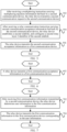
- FIG. 1 is a flowchart 1 of a multiplexing method for a sidelink according to an embodiment of this application, including the following steps 102 and 104.
- Step 102 A relay device receives a first communication request for communicating with a second communication device from a first communication device, and obtains a first relay layer 2 identifier of an established first sidelink of the second communication device; and in this embodiment, the first communication device (UE) transmits the first communication request to the relay device (relay UE), so as to establish a relay device ⁇ of the first communication ⁇ device and a second sidelink of the second communication device.
- the first communication request may carry user information (user info) of the second communication device (target UE), for example, an application layer identifier of a target device (target UE's Application layer ID).
- the relay device retrieves whether there is a second communication device in a currently established sidelink, that is, checks whether there is a first sidelink between another communication device and the second communication device except the first communication device in a communication range of the relay device.
- a first relay layer 2 identifier configured by the relay device for the first sidelink is obtained.
- the first communication device is user equipment at transmitting side that transmits the first communication request
- the second communication device is a requested target device at receiving side.
- a communication device includes but is not limited to a terminal, and the terminal includes but is not limited to a mobile communication device, a tablet computer, a computer, a notebook computer, a wearable device, a vehicle-mounted communication device, or the like.
- Step 104 The relay device establishes a second sidelink between the first communication device and the second communication device according to the first relay layer 2 identifier.
- first sidelink or the second sidelink includes two links, one of which is a link between the first communication device and the relay device, and the other is a link between the relay device and the second communication device.
- the first relay layer 2 identifier of the first sidelink that has established communication with the second communication device is used to establish a second sidelink between the first communication device and the second communication device, so that a link between the relay device of the second sidelink and the second communication device multiplexes a link between the relay device of the first sidelink and the second communication device. Therefore, a sidelink that is requested to be established is multiplexed to the existing first sidelink, thereby implementing multiplexing of sidelinks of a plurality of user equipments, improving resource utilization and scheduling efficiency, reducing a bandwidth requirement for resource transmission, and simultaneously further effectively reducing operating costs.
- user equipment UE-1 (a first communication device) establishes a sidelink with a target device target LTE (a second communication device) through a relay device relay UE, a link between the UE-1 and the relay UE is a link#1a, and a link between the relay UE and the target UE is a link#1b.
- User equipment UE-2 (a first communication device) establishes a sidelink with a target device target UE through a relay device relay UE, a link between the UE-2 and the relay UE is a link#2a, and a link between the relay UE and the target UE is a link#2b.
- the relay UE performs link multiplexing, data or signaling on the link#2b may be multiplexed to the link#1b. That is, the UE-1 and the UE-2 share the link#1b.
- a process in which the relay device establishes a second sidelink between the first communication device and the second communication device according to the first relay layer 2 identifier may include any one of the following manners.
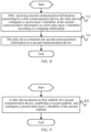
- FIG. 2 is a flowchart 2 of a multiplexing method for a sidelink according to an embodiment of this application, including:
- the relay device first establishes the second sidelink between the first communication device and the second communication device, and then multiplexes the first relay layer 2 identifier of the first sidelink, that is, the relay device ⁇ of the first communication device ⁇ .
- the second relay layer 2 identifier of the second sidelink of the second communication device is the same as the first relay layer 2 identifier of the first sidelink.
- the first communication device and the second communication device may share the link between the second communication device and the relay device in the established first sidelink, and then perform link multiplexing of the first sidelink, improving resource utilization and scheduling efficiency.
- user equipment UE-1 (a first communication device) establishes a sidelink link#1 (a first sidelink) with a target device target UE (a second communication device) through a relay device relay UE, a link between the UE-1 and the relay UE is a link#1a, and a link between the relay UE and the target UE is a link#1b.
- the relay UE receives a link establishment request from the user equipment UE-2 (the first communication device)
- a request message may carry user information of the target UE
- the sidelink link#2 (the second sidelink) of UE-2 ⁇ relay UE ⁇ target UE is established.
- the relay UE multiplexes the relay L2 ID of the link#1, so that the relay UE may multiplex signaling or data of different source UEs (UE-1 and UE-2) to the link#1b.
- FIG. 3 is a flowchart 3 of a multiplexing method for a sidelink according to an embodiment of this application, including:
- the relay device establishes a mapping relationship between the second relay layer 2 identifier and the first relay layer 2 identifier.
- the relay device may multiplex the signaling or data of different source communication devices to the first sidelink according to the mapping relationship, and then perform link multiplexing of the first sidelink according to the mapping relationship, thereby improving resource utilization and scheduling efficiency.
- user equipment UE-1 (a first communication device) establishes a sidelink link#1 (a first sidelink) with a target device target UE (a second communication device) through a relay device relay UE, a link between the UE-1 and the relay UE is a link#1a, and a link between the relay UE and the target UE is a link#1b.
- the LTE-2 (the first communication device) establishes a requirement for establishing a relay connection with the target UE through the relay UE
- the request message may carry the user information of the target UE, and the relay UE determines to multiplex the link#1b of the link#1.
- the relay LTE and the target LTE are in a relay connection manner, and the sidelink link#2 (the second sidelink) of UE-2 ⁇ relay UE ⁇ target LTE is established.
- the relay LTE allocates a new relay L2 ID' (a relay layer 2 identifier) for the link#2, and the relay LTE establishes a mapping relationship between the relay L2 ID' of the link#2 and the relay L2 ID of the link#1.
- the relay UE may learn the relay L2 ID of the link#1 according to the mapping relationship, and then complete link multiplexing of data or signaling on the link#1b, so that transmission on a plurality of paths is simultaneously performed on one physical channel.
- FIG. 4 is a flowchart 4 of a multiplexing method for a sidelink according to an embodiment of this application, including:
- the multiplexing acceptance information includes at least one of the following: user information of the second communication device (target UE user info), quality of service information (QoS info), and a service type.
- a multiplexing request carrying the link multiplexing negotiation information is transmitted to the second communication device, to query whether the second communication device performs link multiplexing. If the second communication device accepts link multiplexing, then the second communication device replies a multiplexing instruction carrying the multiplexing acceptance information to the relay device. After receiving a multiplexing instruction fed back by the second communication device, the relay device confirms that a link multiplexing operation is performed, and establishes a second sidelink between the first communication device and the second communication device according to the first relay layer 2 identifier.
- FIG. 5 is a flowchart 5 of a multiplexing method for a sidelink according to an embodiment of this application, including:
- the relay device transmits the second communication request of the first communication device to the second communication device, to query whether the second communication device accepts the first communication device to establish a second sidelink with the second communication device through the relay device. If the second communication device confirms to perform communication, the second communication device replies the relay communication instruction carrying the second communication acceptance information to the relay device. After the relay device receives the relay communication instruction, the relay device feeds back the second communication acceptance information to the first communication device, establishes an independent second sidelink, and simultaneously configures a second relay layer 2 identifier for the second sidelink, that is, does not perform multiplexing of the first sidelink.
- FIG. 6 is a flowchart 6 of a multiplexing method for a sidelink according to an embodiment of this application, including: step 602.
- the relay device transmits the first communication acceptance information to the first communication device.
- the first communication acceptance information uses or carries the first relay layer 2 identifier. That is, the first relay layer 2 identifier is used as the data frame or the header of the data frame of the first communication acceptance information; and the first communication acceptance information further includes the multiplexing acceptance information.
- the second communication device if the second communication device accepts link multiplexing, then the second communication device replies the first communication acceptance information including the multiplexing instruction to the relay device. After receiving the relay communication acceptance information fed back by the second communication device, the relay device performs a multiplexing operation of the first sidelink, and feeds back the first communication acceptance information to the first communication device, so that the first communication device learns a multiplexing state and parameter of the first sidelink in time, and completes connection establishment of the second sidelink.
- FIG. 7 is a flowchart 7 of a multiplexing method for a sidelink according to an embodiment of this application, including:
- a plurality of first communication devices establish a connection with the second communication device through the same sidelink.
- the second communication device transmits data to different first communication devices (source LTE, source user equipment)
- the second communication device needs to transmit first communication information carrying user information of the first communication device.
- the relay device may determine a first communication device associated with the transmitted data or signaling, and transmit the first communication information to the first communication device corresponding to the user information. In this way, configuration negotiation between the relay device and the second communication device configured to perform lower layer (Lower layer) multiplexing is performed, so as to avoid confusion in information transmission and improve communication reliability and security.
- FIG. 8 is a flowchart 8 of a multiplexing method for a sidelink according to an embodiment of this application, including:
- a plurality of first communication devices establish a connection with the second communication device through the same sidelink.
- the relay device configures a source layer 2 identifier of the forwarded second communication information as the first relay layer 2 identifier, and transmits the second communication information to the second communication device, so as to transmit data or signaling to the second communication device through the link between the second communication device and the relay device in the first sidelink.
- FIG. 9 is a flowchart 9 of a multiplexing method for a sidelink according to an embodiment of this application, including: step 802.
- the relay device detects no first sidelink of the second communication device, establishes the second sidelink, and configures a second relay layer 2 identifier of the second sidelink.
- the relay device retrieves the currently established sidelink and there is no second communication device indicated by the first communication request, that is, link multiplexing cannot be performed, the second communication link between the first communication device and the second communication device is directly established.
- the relay device before establishing the second communication link, the relay device first forwards the first communication request of the first communication device to the second communication device, to query whether the second communication device accepts the first communication device to establish a second sidelink with the second communication device through the relay device. After the relay device receives the communication acceptance instruction transmitted by the second communication device, the relay device establishes the second communication link between the first communication device and the second communication device, and configures a second relay layer 2 identifier for the second communication link, thereby improving the security of the communication system.
- FIG. 13 is a schematic diagram of an operation among a relay device, a first communication device, and a second communication device in a wireless network according to an embodiment of this application.
- the embodiments of this application are specifically described through FIG. 13 .
- the first communication device includes UE-1 and UE-2.
- the UE-1 has established a sidelink link#1 through the relay UE and the target UE, a link between the UE1 and the relay UE is a link#1a, and a link between the relay UE and the target UE is a link#1b.
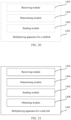
- FIG. 15 is a structural block diagram 1 of a multiplexing apparatus for a sidelink according to an embodiment of this application.
- the multiplexing apparatus 1300 for the sidelink includes: a receiving module 1302, where the receiving module 1302 is configured to receive a first communication request for communicating with a second communication device from a first communication device; an obtaining module 1304, where the obtaining module 1304 is configured to obtain a first relay layer 2 identifier of an established first sidelink of the second communication device; and an establishment module 1306, where the establishment module 1306 is configured to establish a second sidelink between the first communication device and the second communication device according to the first relay layer 2 identifier.
- the establishment module 1306 is specifically configured to: establish the second sidelink; and configure a second relay layer 2 identifier of the second sidelink as the first relay layer 2 identifier, to perform link multiplexing of the first sidelink.
- the establishment module 1306 is specifically configured to: establish the second sidelink, and configure a second relay layer 2 identifier of the second sidelink; and establish a mapping relationship between the second relay layer 2 identifier and the first relay layer 2 identifier, to perform link multiplexing of the first sidelink according to the mapping relationship.
- FIG. 16 is a structural block diagram 2 of a multiplexing apparatus for a sidelink according to an embodiment of this application.
- the multiplexing apparatus 1300 for the sidelink further includes: a transmitting module 1308, where the transmitting module 1308 is configured to transmit a multiplexing request carrying multiplexing negotiation information of the sidelink to the second communication device, where the multiplexing negotiation information uses or carries the first relay layer 2 identifier; and the multiplexing request includes any one of the following: the first communication request, a link modification request, and PC5 signaling.
- the multiplexing negotiation information includes at least one of the following: user information of the first communication device, user information of the relay device, user information of the second communication device, quality of service information, a service type, and a logical channel identifier.
- the receiving module 1302 is further configured to receive a multiplexing instruction carrying multiplexing acceptance information or multiplexing rejection information fed back by the second communication device.
- the receiving module 1302 is further configured to receive a multiplexing instruction or a relay communication instruction fed back by the second communication device, where the multiplexing instruction carries the multiplexing acceptance information or the multiplexing rejection information, and the relay communication instruction carries second communication acceptance information or the communication rejection information.
- the transmitting module 1308 is further configured to transmit the first communication acceptance information or the second communication acceptance information to the first communication device, where the first communication acceptance information uses or carries the first relay layer 2 identifier; and the first communication acceptance information further includes the multiplexing acceptance information.
- the receiving module 1302 is further configured to receive first communication information transmitted by the second communication device; the obtaining module 1304 is further configured to determine user information in the first communication information; and the transmitting module 1308 is further configured to transmit the first communication information to the first communication device corresponding to the user information.
- the receiving module 1302 is further configured to receive second communication information transmitted by the first communication device; the establishment module 1306 is further configured to configure a source layer 2 identifier of the second communication information as the first relay layer 2 identifier according to the mapping relationship; and the transmitting module 1308 is further configured to transmit the second communication information to the second communication device.
- a relay device 1600 including a processor 1604, a memory 1602, and a program or an instruction stored in the memory 1602 and executable on the processor 1604, where when the program or the instruction is executed by the processor 1604, steps of the multiplexing method for a sidelink provided in any one of the embodiments are implemented. Therefore, the relay device 1600 includes all beneficial effects of the multiplexing method for a sidelink provided in any one of the embodiments, which will not be repeated herein.
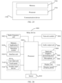
- FIG. 26 is a schematic diagram of a hardware structure of a relay device 1800 according to an embodiment of this application.
- the relay device 1800 includes, but is not limited to, components such as a radio frequency unit 1802, a network module 1804, an audio output unit 1806, an input unit 1808, a sensor 1810, a display unit 1812, a user input unit 1814, an interface unit 1816, a memory 1818, and a processor 1820.
- the relay device 1800 may further include the power supply (such as a battery) for supplying power to the components.
- the power supply may be logically connected to the processor 1820 by a power management system, thereby implementing functions such as charging, discharging, and power consumption management by using the power management system.
- a structure of a relay device shown in FIG. 26 does not constitute a limitation to the relay device, and the relay device may include more or fewer components than those shown in the figure, or some components may be combined, or a different component deployment may be used.
- the relay device includes, but is not limited to, a mobile terminal, a tablet computer, a notebook computer, a palmtop computer, an in-vehicle electronic device, a wearable device, a pedometer, and the like.
- the radio frequency unit 1802 is configured to receive a first communication request for the first communication device to communicate with the second communication device, and the processor 1820 is configured to obtain a first relay layer 2 identifier of the established first sidelink of the second communication device; and establish a second sidelink between the first communication device and the second communication device according to the first relay layer 2 identifier.
- the processor 1820 is specifically configured to establish the second sidelink; and configure the second relay layer 2 identifier of the second sidelink as the first relay layer 2 identifier, to perform link multiplexing of the first sidelink, or configure the second relay layer 2 identifier of the second sidelink, and establish a mapping relationship between the second relay layer 2 identifier and the first relay layer 2 identifier, to perform link multiplexing of the first sidelink according to the mapping relationship.
- the radio frequency unit 1802 is further configured to transmit a multiplexing request carrying multiplexing negotiation information of the sidelink to the second communication device, and receive a multiplexing instruction carrying multiplexing acceptance information or multiplexing rejection information fed back by the second communication device.
- the processor 1820 is further configured to receive a multiplexing instruction carrying multiplexing acceptance information fed back by the second communication device, and establish the second sidelink according to the first relay layer 2 identifier.
- the radio frequency unit 1802 is further configured to transmit a second communication request to the second communication device, receive a relay communication instruction carrying second communication acceptance information fed back by the second communication device, and transmit the second communication acceptance information to the first communication device; and the processor 1820 is further configured to receive a relay communication instruction carrying second communication acceptance information fed back by the second communication device, establish the second sidelink, and configure a second relay layer 2 identifier of the second sidelink.
- the radio frequency unit 1802 is further configured to transmit the first communication acceptance information to the first communication device, where the first communication acceptance information uses or carries the first relay layer 2 identifier; and the first communication acceptance information further includes the multiplexing acceptance information.
- the radio frequency unit 1802 is further configured to receive first communication information transmitted by the second communication device, and transmit the first communication information to the first communication device corresponding to the user information; and the processor 1820 is further configured to determine user information in the first communication information.
- the radio frequency unit 1802 is further configured to receive second communication information transmitted by the first communication device; and transmit the second communication information to the second communication device; and the processor 1820 is further configured to configure a source layer 2 identifier of the second communication information as the first relay layer 2 identifier according to the mapping relationship.
- the radio frequency unit 1802 may be configured to receive and transmit information or receive and transmit signals during a call, specifically, receive downlink data from a base station or transmit uplink data to a base station.
- the radio frequency unit 1802 includes, but is not limited to, an antenna, at least one amplifier, a transceiver, a coupler, a low noise amplifier, a duplexer, and the like.
- a network module 1804 provides the user with wireless broadband Internet access, such as helping the user to send and receive emails, browse web pages, and access streaming media.
- the audio output unit 1806 may convert audio data received by the radio frequency unit 1802 or the network module 1804 or stored on the memory 1818 into audio signals and output the audio signals as sounds. In addition, the audio output unit 1806 may further provide an audio output that is related to a particular function executed by the relay device 1800 (for example, a call signal receiving sound or a message receiving sound).
- the audio output unit 1806 includes a speaker, a buzzer, a receiver, and the like.
- An input unit 1808 is configured to receive an audio signal or a video signal.
- the input unit 1808 may include a graphics processing unit (GPU) 5082 and a microphone 5084.
- the GPU 5082 processes image data of a static picture or a video obtained by an image capturing device (for example, a camera) in a video capturing mode or an image capturing mode.
- the processed image frame may be displayed on the display unit 1812, or stored on the memory 1818 (or another storage medium), or transmitted through the radio frequency unit 1802 or the network module 1804.
- the microphone 5084 may receive sound and process the sound into audio data.
- the processed audio data may be transferred, in a phone talk mode, to a format that may be sent to a mobile communication base station via the radio frequency unit 1802 to output.
- the relay device 1800 further includes at least one sensor 1810, such as a fingerprint sensor, a pressure sensor, an iris sensor, a molecular sensor, a gyroscope, a barometer, a hygrometer, a thermometer, an infrared sensor, a light sensor, a motion sensor, or the like.
- a fingerprint sensor such as a fingerprint sensor, a pressure sensor, an iris sensor, a molecular sensor, a gyroscope, a barometer, a hygrometer, a thermometer, an infrared sensor, a light sensor, a motion sensor, or the like.
- a sensor 1810 such as a fingerprint sensor, a pressure sensor, an iris sensor, a molecular sensor, a gyroscope, a barometer, a hygrometer, a thermometer, an infrared sensor, a light sensor, a motion sensor, or the like.
- the display unit 1812 may be configured to display information input by the user or information provided for the user.
- the display unit 1812 may include a display panel 5122, and the display panel 5122 may be configured by using a liquid crystal display, an organic light-emitting diode, or the like.
- a user input unit 1814 may be configured to: receive input numeral or character information, and generate a key signal input related to a user setting and function control of the relay device.
- the user input unit 1814 includes a touch panel 5142 and another input device 5144.
- the touch panel 5142 is also referred to as a touch screen, which may collect a touch operation of a user on or near the touch panel.
- the touch panel 5142 may include two parts: a touch detection apparatus and a touch controller.
- the touch detection apparatus detects a touch orientation of the user, detects a signal brought through the touch operation, and transmits the signal to the touch controller.
- the touch controller receives the touch information from the touch detection apparatus, converts the touch information into touch point coordinates, and transmits the touch point coordinates to the processor 1820.
- the touch controller may receive and execute a command transmitted from the processor 1820.
- the another input device 5144 may include, but not limited to, a physical keyboard, a functional key (such as a volume control key or a switch key), a track ball, a mouse, and a joystick, which are not described herein in detail.
- the touch panel 5142 may cover the display panel 5122. After detecting a touch operation on or near the touch panel 5142, the touch panel transfers the touch operation to the processor 1820, to determine a type of a touch event. Then, the processor 1820 provides a corresponding visual output on the display panel 5122 according to the type of the touch event.
- the touch panel 5142 and the display panel 5122 may be used as two independent components, or may be integrated into one component.
- the interface unit 1816 is an interface for connecting an external apparatus to the relay device 1800.
- the external apparatus may include a wired or wireless headset port, an external power supply (or a battery charger) port, a wired or wireless data port, a storage card port, a port used to connect an apparatus having an identification module, an audio input/output (I/O) port, a video I/O port, an earphone port, and the like.
- the interface unit 1816 may be configured to receive an input (such as data information or electric power) from an external apparatus and transmit the received input to one or more elements in the relay device 1800 or may be configured to transmit data between the relay device 1800 and an external apparatus.
- the memory 1818 may be configured to store a software program and various data.
- the memory 1818 may mainly include a program storage area and a data storage area.
- the program storage area may store an operating system, an application program required by at least one function (such as a sound playback function and an image display function), and the like.
- the data storage area may store data (such as audio data and an address book) created according to the use of the mobile terminal, and the like.
- the memory 1818 may include a high-speed random access memory, and may also include a nonvolatile memory, for example, at least one magnetic disk storage device, a flash memory, or another volatile solid-state storage device.
- the processor 1820 By running or executing the software program and/or module stored in the memory 1818, and invoking data stored in the memory 1818, the processor 1820 performs various functions and data processing of the relay device 1800, thereby performing overall monitoring on the relay device 1800.
- the processor 1820 may include one or more processing units.
- the processor 1820 may integrate an application processor and a modem.
- the application processor mainly processes an operating system, a user interface, an application, and the like.
- the modem mainly processes multiplexing of the sidelink.
- FIG. 17 is a flowchart 10 of a multiplexing method for a sidelink according to an embodiment of this application, including:
- the second communication device determines the multiplexing information of the multiplexing negotiation information in response to a second input by a user or according to a multiplexing rule preset by a user.
- the second communication device transmits a multiplexing instruction carrying multiplexing information to the relay device, so as to feed back to the relay device whether to perform multiplexing of the first sidelink.
- the multiplexing instruction includes confirming the multiplexing instruction; and FIG. 18 is a flowchart 11 of a multiplexing method for a sidelink according to an embodiment of this application, including:
- the second communication device determines second communication acceptance information or communication rejection information of the first communication request in response to a third input by the user or according to the communication rule preset by the user.
- the second communication device transmits a relay communication instruction carrying second communication acceptance information or communication rejection information to the relay device, so as to feed back to the relay device whether to accept the first communication request of the first communication device.
- the multiplexing instruction includes confirming the multiplexing instruction; and FIG. 19 is a flowchart 12 of a multiplexing method for a sidelink according to an embodiment of this application, including:
- the first communication information includes user information of the first communication device.
- a plurality of first communication devices establish communication with the second communication device through the first sidelink.
- the second communication device transmits data to the first communication device (source UE, source user equipment)
- the second communication device needs to transmit first communication information carrying user information of the first communication device.
- the relay device may determine a source communication device associated with the transmitted data or signaling, so that the relay device transmits the first communication information to the first communication device corresponding to the user information. In this way, configuration negotiation between the relay device and the second communication device configured to perform lower layer (Lower layer) multiplexing is performed, so as to avoid confusion in information transmission and improve communication reliability and security.
- FIG. 20 is a structural block diagram 3 of a multiplexing apparatus for a sidelink according to an embodiment of this application.
- the multiplexing apparatus 1400 for the sidelink includes: a receiving module 1402, where the receiving module 1402 is configured to receive a multiplexing request carrying multiplexing negotiation information of a sidelink transmitted by the relay device; a determining module 1404, where the determining module 1404 is configured to determine multiplexing information according to the multiplexing negotiation information; and a transmitting module 1406, where the transmitting module 1406 is configured to transmit a multiplexing instruction carrying the multiplexing information to the relay device.
- the multiplexing information includes multiplexing acceptance information or multiplexing rejection information; and the multiplexing instruction includes any one of the following: a relay communication instruction, a link modification instruction, and PC5 signaling.
- the multiplexing negotiation information includes at least one of the following: user information of the first communication device, user information of the second communication device, user information of the relay device, quality of service information, a service type, and a logical channel identifier.
- the receiving module 1402 is further configured to receive a second communication request from the first communication device to the second communication device transmitted by the relay device; and the determining module 1404 is further configured to determine acceptance information or communication rejection information of the second communication request.
- the transmitting module 1406 is further configured to transmit a relay communication instruction carrying the second communication acceptance information or the communication rejection information to the relay device.
- the transmitting module 1406 is further configured to transmit first communication information to be transmitted to a first communication device to the relay device.
- FIG. 21 is a structural block diagram 4 of a multiplexing apparatus for a sidelink according to an embodiment of this application.
- the multiplexing apparatus 1400 for the sidelink further includes: an obtaining module 1408, where the obtaining module 1408 is configured to obtain first communication information to be transmitted to the first communication device.
- the transmitting module 1406 is further configured to transmit the first communication information to the relay device, where the first communication information includes user information of the first communication device.
- FIG. 22 is a flowchart 13 of a multiplexing method for a sidelink according to an embodiment of this application, including:
- the first communication device may communicate with the second communication device through the relay device.
- the method further includes: obtaining, by the first communication device, the second communication information to be transmitted to the second communication device; and transmitting, by the first communication device, the second communication information to the relay device.
- the first communication device may transmit data or signaling to the second communication device through the relay device, thereby improving reduction of a signal-to-noise ratio and degradation of quality of service caused by channel fading and the device being too far away, and reducing a limitation on a communication range.
- FIG. 23 is a structural block diagram 5 of a multiplexing apparatus for a sidelink according to an embodiment of this application.
- the multiplexing apparatus 1500 for the sidelink further includes: a determining module 1502, where the determining module 1502 is configured to determine a second communication device corresponding to a first communication device; a transmitting module 1504, where the transmitting module 1504 is configured to transmit a first communication request for the first communication device to communicate with the second communication device to a relay device; and a receiving module 1506, where the receiving module 1506 is configured to receive first communication acceptance information or second communication acceptance information fed back by the relay device.
- a communication device 1700 including: a memory 1702, on which a computer program is stored; and a processor 1704, configured to execute a computer program to implement steps of the multiplexing method for a sidelink provided in any one of the embodiments. Therefore, the communication device 1700 includes all beneficial effects of the multiplexing method for a sidelink provided in any one of the embodiments, which will not be repeated herein.
- the communication device in the embodiments of this application may be an apparatus, and may also be a component in a terminal, an integrated circuit, or a chip.
- the apparatus may be a mobile electronic device, or may be a non-mobile electronic device.
- the mobile electronic device may be a mobile phone, a tablet computer, a notebook computer, a handheld computer, a vehicle-mounted electronic device, a wearable device, an ultra-mobile personal computer (ultra-mobile personal computer, UMPC), a netbook, a personal digital assistant (personal digital assistant, PDA), or the like.
- the non-mobile terminal may be a server, a network attached storage (network attached storage, NAS), a personal computer (personal computer, PC), a television (television, TV), a cash machine, a self-service machine, or the like, which is not specifically limited in the embodiments of this application.
- NAS network attached storage
- PC personal computer
- TV television
- TV cash machine
- self-service machine or the like, which is not specifically limited in the embodiments of this application.
- the communication device in the embodiments of this application may be an apparatus having an operating system.
- the operating system may be an Android (Android) operating system, may be an ios operating system, and may further be another possible operating system, which is not specifically limited in this embodiment of this application.
- a readable storage medium storing a program or an instruction, where when the program or the instruction is executed by a processor, steps of the multiplexing method for a sidelink provided in any one of the embodiments are implemented.
- the readable storage medium may implement various processes of the multiplexing method for a sidelink provided in the embodiments of this application, and may implement the same technical effect, which will not be repeated herein to avoid repetition.
- the processor is a processor in the communication device in the foregoing embodiment.
- the readable storage medium includes a computer-readable storage medium, for example, a read-only memory (Read-Only Memory, ROM), a random access memory (Random Access Memory, RAM), a magnetic disk, an optical disc or the like.
- a readable storage media may be either volatile or non-volatile.
- the readable storage medium in the embodiments of this application may be non-transitory.
- the embodiments of this application further provide a chip, including a processor and a communication interface, where the communication interface is coupled to the processor.
- the processor is configured to run a program or an instruction, to implement various processes of embodiments of the multiplexing method for a sidelink, and may implement the same technical effect, which will not be described in detail herein again to avoid repetition.
- chip mentioned in the embodiments of this application may further be referred to as a system-level chip, a system chip, a chip system, a system on chip, or the like.
- connection may be a fixing connection, a detachable connection, or an integral connection; and “connected” may be a direct connection or an indirect connection by using an intermediary.
- connection may be a fixing connection, a detachable connection, or an integral connection; and “connected” may be a direct connection or an indirect connection by using an intermediary.
- first, second, and the like are intended to distinguish between different objects but do not indicate a particular order of an object.
Landscapes
- Engineering & Computer Science (AREA)
- Computer Networks & Wireless Communication (AREA)
- Signal Processing (AREA)
- Mobile Radio Communication Systems (AREA)
Applications Claiming Priority (2)
| Application Number | Priority Date | Filing Date | Title |
|---|---|---|---|
| CN202011141023.6A CN114390635B (zh) | 2020-10-22 | 2020-10-22 | 中继链路的复用方法、装置、中继设备、通信设备和介质 |
| PCT/CN2021/124440 WO2022083546A1 (zh) | 2020-10-22 | 2021-10-18 | 中继链路的复用方法、装置、中继设备、通信设备和介质 |
Publications (2)
| Publication Number | Publication Date |
|---|---|
| EP4236470A1 true EP4236470A1 (de) | 2023-08-30 |
| EP4236470A4 EP4236470A4 (de) | 2024-04-10 |
Family
ID=81194905
Family Applications (1)
| Application Number | Title | Priority Date | Filing Date |
|---|---|---|---|
| EP21881962.1A Pending EP4236470A4 (de) | 2020-10-22 | 2021-10-18 | Verfahren und vorrichtung zum multiplexen einer relaisverbindung, relaisvorrichtung, kommunikationsvorrichtungen und medium |
Country Status (3)
| Country | Link |
|---|---|
| EP (1) | EP4236470A4 (de) |
| CN (1) | CN114390635B (de) |
| WO (1) | WO2022083546A1 (de) |
Cited By (3)
| Publication number | Priority date | Publication date | Assignee | Title |
|---|---|---|---|---|
| US12200788B1 (en) * | 2023-07-13 | 2025-01-14 | Asus Technology Licensing Inc. | Method and apparatus for relay UE adding source end UE for UE-to-UE relay communication in a wireless communication system |
| WO2025095569A1 (ko) * | 2023-11-01 | 2025-05-08 | 삼성전자 주식회사 | 무선 통신 시스템에서 데이터의 전송을 위한 방법 및 장치 |
| EP4625839A4 (de) * | 2023-04-03 | 2026-03-04 | Guangdong Oppo Mobile Telecommunications Corp Ltd | Kommunikationsverfahren und vorrichtungen |
Families Citing this family (1)
| Publication number | Priority date | Publication date | Assignee | Title |
|---|---|---|---|---|
| GB2627257A (en) * | 2023-02-17 | 2024-08-21 | Nokia Technologies Oy | Method and apparatus for relayed connection between nodes |
Family Cites Families (3)
| Publication number | Priority date | Publication date | Assignee | Title |
|---|---|---|---|---|
| WO2017039735A1 (en) * | 2015-09-03 | 2017-03-09 | Intel IP Corporation | User equipment, and evolved node bs supporting layer-2 relaying and route switching |
| US10893557B2 (en) * | 2017-05-05 | 2021-01-12 | Qualcomm Incorporated | Relaying in a device-to-device communication system |
| CN110602801B (zh) * | 2019-08-09 | 2022-04-05 | 北京紫光展锐通信技术有限公司 | 链路配置方法及装置 |
-
2020
- 2020-10-22 CN CN202011141023.6A patent/CN114390635B/zh active Active
-
2021
- 2021-10-18 WO PCT/CN2021/124440 patent/WO2022083546A1/zh not_active Ceased
- 2021-10-18 EP EP21881962.1A patent/EP4236470A4/de active Pending
Cited By (4)
| Publication number | Priority date | Publication date | Assignee | Title |
|---|---|---|---|---|
| EP4625839A4 (de) * | 2023-04-03 | 2026-03-04 | Guangdong Oppo Mobile Telecommunications Corp Ltd | Kommunikationsverfahren und vorrichtungen |
| US12200788B1 (en) * | 2023-07-13 | 2025-01-14 | Asus Technology Licensing Inc. | Method and apparatus for relay UE adding source end UE for UE-to-UE relay communication in a wireless communication system |
| US20250024535A1 (en) * | 2023-07-13 | 2025-01-16 | Asus Technology Licensing Inc. | Method and apparatus for relay ue adding source end ue for ue-to-ue relay communication in a wireless communication system |
| WO2025095569A1 (ko) * | 2023-11-01 | 2025-05-08 | 삼성전자 주식회사 | 무선 통신 시스템에서 데이터의 전송을 위한 방법 및 장치 |
Also Published As
| Publication number | Publication date |
|---|---|
| CN114390635B (zh) | 2023-09-26 |
| EP4236470A4 (de) | 2024-04-10 |
| CN114390635A (zh) | 2022-04-22 |
| WO2022083546A1 (zh) | 2022-04-28 |
Similar Documents
| Publication | Publication Date | Title |
|---|---|---|
| EP4236470A1 (de) | Verfahren und vorrichtung zum multiplexen einer relaisverbindung, relaisvorrichtung, kommunikationsvorrichtungen und medium | |
| EP3833152B1 (de) | Umverteilungsverfahren und endgerät | |
| JP7373570B2 (ja) | 接続確立方法、端末機器及びネットワーク機器 | |
| EP3793319A1 (de) | Trägerkonfigurationsverfahren für die wiederherstellung einer rrc-verbindung, endgerät und netzwerkvorrichtung | |
| CN111132224B (zh) | sidelink的连接控制方法、终端及网络侧设备 | |
| US12245326B2 (en) | Message transmission method and terminal | |
| EP3965524B1 (de) | Verfahren, vorrichtungen und system zum aufbau einer pc5-verbindung | |
| CN111132371B (zh) | 副链路连接建立、资源分配方法、终端及网络侧设备 | |
| EP4178311B1 (de) | Datenübertragungsverfahren und netzwerkseitige vorrichtung | |
| WO2020038294A1 (zh) | 传输方法及终端设备 | |
| US20210258840A1 (en) | Cell handover method, terminal, and communication node | |
| US20210176684A1 (en) | Terminal camping method, information transmission method, terminal, and network device | |
| CN111436026B (zh) | 副链路组播通信的配置方法和终端 | |
| CN113329322A (zh) | 数据传输方法、装置、终端及网络侧设备 | |
| CN111836379A (zh) | 辅助信息上报方法、配置方法、终端和网络侧设备 | |
| WO2020029760A1 (zh) | 资源配置方法和装置 | |
| US11503574B2 (en) | Information interaction method and terminal | |
| JP7392106B2 (ja) | データ送信方法及びユーザ機器 | |
| WO2019242464A1 (zh) | 一种资源指示方法、装置及系统 | |
| WO2020244479A1 (zh) | 连接管理方法、终端及网络侧设备 | |
| CN112770406B (zh) | 先听后说lbt失败的恢复方法、用户设备和基站 | |
| RU2791284C1 (ru) | Способ повторного выбора реле, устройство и носитель | |
| HK40085803B (en) | Data transmission methods and network side devices | |
| HK40061256B (en) | Pc5 link establishment methods, devices and system | |
| HK40067932A (en) | Message transmission method and terminal |
Legal Events
| Date | Code | Title | Description |
|---|---|---|---|
| STAA | Information on the status of an ep patent application or granted ep patent |
Free format text: STATUS: THE INTERNATIONAL PUBLICATION HAS BEEN MADE |
|
| PUAI | Public reference made under article 153(3) epc to a published international application that has entered the european phase |
Free format text: ORIGINAL CODE: 0009012 |
|
| STAA | Information on the status of an ep patent application or granted ep patent |
Free format text: STATUS: REQUEST FOR EXAMINATION WAS MADE |
|
| 17P | Request for examination filed |
Effective date: 20230512 |
|
| AK | Designated contracting states |
Kind code of ref document: A1 Designated state(s): AL AT BE BG CH CY CZ DE DK EE ES FI FR GB GR HR HU IE IS IT LI LT LU LV MC MK MT NL NO PL PT RO RS SE SI SK SM TR |
|
| DAV | Request for validation of the european patent (deleted) | ||
| DAX | Request for extension of the european patent (deleted) | ||
| A4 | Supplementary search report drawn up and despatched |
Effective date: 20240311 |
|
| RIC1 | Information provided on ipc code assigned before grant |
Ipc: H04W 88/04 20090101ALN20240304BHEP Ipc: H04W 76/23 20180101ALI20240304BHEP Ipc: H04W 76/18 20180101ALI20240304BHEP Ipc: H04W 76/15 20180101ALI20240304BHEP Ipc: H04W 76/14 20180101ALI20240304BHEP Ipc: H04W 40/24 20090101ALI20240304BHEP Ipc: H04W 40/22 20090101AFI20240304BHEP |