EP4236471A1 - Procédé et appareil pour implémenter la mobilité dans un système de communication sans fil - Google Patents
Procédé et appareil pour implémenter la mobilité dans un système de communication sans fil Download PDFInfo
- Publication number
- EP4236471A1 EP4236471A1 EP21883349.9A EP21883349A EP4236471A1 EP 4236471 A1 EP4236471 A1 EP 4236471A1 EP 21883349 A EP21883349 A EP 21883349A EP 4236471 A1 EP4236471 A1 EP 4236471A1
- Authority
- EP
- European Patent Office
- Prior art keywords
- wireless device
- information
- network
- connection
- wireless
- Prior art date
- Legal status (The legal status is an assumption and is not a legal conclusion. Google has not performed a legal analysis and makes no representation as to the accuracy of the status listed.)
- Granted
Links
Images








Classifications
-
- H—ELECTRICITY
- H04—ELECTRIC COMMUNICATION TECHNIQUE
- H04W—WIRELESS COMMUNICATION NETWORKS
- H04W76/00—Connection management
- H04W76/10—Connection setup
-
- H—ELECTRICITY
- H04—ELECTRIC COMMUNICATION TECHNIQUE
- H04W—WIRELESS COMMUNICATION NETWORKS
- H04W36/00—Hand-off or reselection arrangements
- H04W36/0005—Control or signalling for completing the hand-off
- H04W36/0055—Transmission or use of information for re-establishing the radio link
- H04W36/0079—Transmission or use of information for re-establishing the radio link in case of hand-off failure or rejection
-
- H—ELECTRICITY
- H04—ELECTRIC COMMUNICATION TECHNIQUE
- H04W—WIRELESS COMMUNICATION NETWORKS
- H04W36/00—Hand-off or reselection arrangements
- H04W36/03—Reselecting a link using a direct mode connection
- H04W36/033—Reselecting a link using a direct mode connection in pre-organised networks
-
- H—ELECTRICITY
- H04—ELECTRIC COMMUNICATION TECHNIQUE
- H04W—WIRELESS COMMUNICATION NETWORKS
- H04W36/00—Hand-off or reselection arrangements
- H04W36/08—Reselecting an access point
-
- H—ELECTRICITY
- H04—ELECTRIC COMMUNICATION TECHNIQUE
- H04W—WIRELESS COMMUNICATION NETWORKS
- H04W36/00—Hand-off or reselection arrangements
- H04W36/24—Reselection being triggered by specific parameters
- H04W36/30—Reselection being triggered by specific parameters by measured or perceived connection quality data
-
- H—ELECTRICITY
- H04—ELECTRIC COMMUNICATION TECHNIQUE
- H04W—WIRELESS COMMUNICATION NETWORKS
- H04W36/00—Hand-off or reselection arrangements
- H04W36/24—Reselection being triggered by specific parameters
- H04W36/32—Reselection being triggered by specific parameters by location or mobility data, e.g. speed data
- H04W36/324—Reselection being triggered by specific parameters by location or mobility data, e.g. speed data by mobility data, e.g. speed data
-
- H—ELECTRICITY
- H04—ELECTRIC COMMUNICATION TECHNIQUE
- H04W—WIRELESS COMMUNICATION NETWORKS
- H04W36/00—Hand-off or reselection arrangements
- H04W36/34—Reselection control
- H04W36/36—Reselection control by user or terminal equipment
-
- H—ELECTRICITY
- H04—ELECTRIC COMMUNICATION TECHNIQUE
- H04W—WIRELESS COMMUNICATION NETWORKS
- H04W36/00—Hand-off or reselection arrangements
- H04W36/34—Reselection control
- H04W36/38—Reselection control by fixed network equipment
-
- H—ELECTRICITY
- H04—ELECTRIC COMMUNICATION TECHNIQUE
- H04W—WIRELESS COMMUNICATION NETWORKS
- H04W4/00—Services specially adapted for wireless communication networks; Facilities therefor
- H04W4/30—Services specially adapted for particular environments, situations or purposes
- H04W4/40—Services specially adapted for particular environments, situations or purposes for vehicles, e.g. vehicle-to-pedestrians [V2P]
-
- H—ELECTRICITY
- H04—ELECTRIC COMMUNICATION TECHNIQUE
- H04W—WIRELESS COMMUNICATION NETWORKS
- H04W40/00—Communication routing or communication path finding
- H04W40/02—Communication route or path selection, e.g. power-based or shortest path routing
- H04W40/12—Communication route or path selection, e.g. power-based or shortest path routing based on transmission quality or channel quality
-
- H—ELECTRICITY
- H04—ELECTRIC COMMUNICATION TECHNIQUE
- H04W—WIRELESS COMMUNICATION NETWORKS
- H04W40/00—Communication routing or communication path finding
- H04W40/02—Communication route or path selection, e.g. power-based or shortest path routing
- H04W40/22—Communication route or path selection, e.g. power-based or shortest path routing using selective relaying for reaching a BTS [Base Transceiver Station] or an access point
-
- H—ELECTRICITY
- H04—ELECTRIC COMMUNICATION TECHNIQUE
- H04W—WIRELESS COMMUNICATION NETWORKS
- H04W76/00—Connection management
- H04W76/10—Connection setup
- H04W76/14—Direct-mode setup
-
- H—ELECTRICITY
- H04—ELECTRIC COMMUNICATION TECHNIQUE
- H04W—WIRELESS COMMUNICATION NETWORKS
- H04W76/00—Connection management
- H04W76/10—Connection setup
- H04W76/19—Connection re-establishment
-
- H—ELECTRICITY
- H04—ELECTRIC COMMUNICATION TECHNIQUE
- H04W—WIRELESS COMMUNICATION NETWORKS
- H04W76/00—Connection management
- H04W76/20—Manipulation of established connections
-
- H—ELECTRICITY
- H04—ELECTRIC COMMUNICATION TECHNIQUE
- H04W—WIRELESS COMMUNICATION NETWORKS
- H04W76/00—Connection management
- H04W76/30—Connection release
-
- H—ELECTRICITY
- H04—ELECTRIC COMMUNICATION TECHNIQUE
- H04W—WIRELESS COMMUNICATION NETWORKS
- H04W88/00—Devices specially adapted for wireless communication networks, e.g. terminals, base stations or access point devices
- H04W88/02—Terminal devices
- H04W88/04—Terminal devices adapted for relaying to or from another terminal or user
-
- H—ELECTRICITY
- H04—ELECTRIC COMMUNICATION TECHNIQUE
- H04W—WIRELESS COMMUNICATION NETWORKS
- H04W92/00—Interfaces specially adapted for wireless communication networks
- H04W92/16—Interfaces between hierarchically similar devices
- H04W92/18—Interfaces between hierarchically similar devices between terminal devices
-
- Y—GENERAL TAGGING OF NEW TECHNOLOGICAL DEVELOPMENTS; GENERAL TAGGING OF CROSS-SECTIONAL TECHNOLOGIES SPANNING OVER SEVERAL SECTIONS OF THE IPC; TECHNICAL SUBJECTS COVERED BY FORMER USPC CROSS-REFERENCE ART COLLECTIONS [XRACs] AND DIGESTS
- Y02—TECHNOLOGIES OR APPLICATIONS FOR MITIGATION OR ADAPTATION AGAINST CLIMATE CHANGE
- Y02D—CLIMATE CHANGE MITIGATION TECHNOLOGIES IN INFORMATION AND COMMUNICATION TECHNOLOGIES [ICT], I.E. INFORMATION AND COMMUNICATION TECHNOLOGIES AIMING AT THE REDUCTION OF THEIR OWN ENERGY USE
- Y02D30/00—Reducing energy consumption in communication networks
- Y02D30/70—Reducing energy consumption in communication networks in wireless communication networks
Definitions
- the present disclosure relates to mobility in wireless communications.
- a wireless communication system is a multiple access system that supports communication with multiple users by sharing available system resources (e.g., bandwidth, transmission power, etc.).
- Examples of the multiple access system include a code division multiple access (CDMA) system, a frequency division multiple access (FDMA) system, a time division multiple access (TDMA) system, an orthogonal frequency division multiple access (OFDMA) system, and a single carrier frequency (SC-FDMA) system.
- CDMA code division multiple access
- FDMA frequency division multiple access
- TDMA time division multiple access
- OFDMA orthogonal frequency division multiple access
- SC-FDMA single carrier frequency
- MC-FDMA division multiple access
- MC-FDMA multi carrier frequency division multiple access
- SL communication is a communication scheme in which a direct link is established between User Equipments (UEs) and the UEs exchange voice and data directly with each other without intervention of an evolved Node B (eNB).
- UEs User Equipments
- eNB evolved Node B
- SL communication is under consideration as a solution to the overhead of an eNB caused by rapidly increasing data traffic.
- V2X Vehicle-to-everything refers to a communication technology through which a vehicle exchanges information with another vehicle, a pedestrian, an object having an infrastructure (or infra) established therein, and so on.
- the V2X may be divided into 4 types, such as vehicle-to-vehicle (V2V), vehicle-to-infrastructure (V2I), vehicle-to-network (V2N), and vehicle-to-pedestrian (V2P).
- V2X communication may be provided via a PC5 interface and/or Uu interface.
- RAT Radio Access Technology
- V2X vehicle-to-everything
- FIG. 1 is a drawing for describing V2X communication based on NR, compared to V2X communication based on RAT used before NR.
- V2X communication a scheme of providing a safety service, based on a V2X message such as Basic Safety Message (BSM), Cooperative Awareness Message (CAM), and Decentralized Environmental Notification Message (DENM) is focused in the discussion on the RAT used before the NR.
- the V2X message may include position information, dynamic information, attribute information, or the like.
- a UE may transmit a periodic message type CAM and/or an event triggered message type DENM to another UE.
- the CAM may include basic vehicle information such as vehicle dynamic state information such as direction and speed, vehicle static data such as dimensions, external lighting conditions, and route details.
- the UE may broadcast CAM, and the latency of CAM may be less than 100 ms.
- a UE may generate a DENM and transmit it to another UE.
- all vehicles within the transmission range of the UE can receive CAM and/or DENM.
- DENM may have a higher priority than CAM.
- V2X communication various V2X scenarios are proposed in NR.
- the various V2X scenarios may include vehicle platooning, advanced driving, extended sensors, remote driving, or the like.
- vehicles can dynamically form groups and move together. For example, to perform platoon operations based on vehicle platooning, vehicles belonging to the group may receive periodic data from the lead vehicle. For example, vehicles belonging to the group may shorten or widen the distance between vehicles using periodic data.
- vehicles can be semi-automated or fully automated.
- each vehicle may adjust trajectories or maneuvers based on data obtained from local sensors of proximate vehicles and/or proximate logical entities.
- each vehicle may mutually share driving intention with nearby vehicles.
- raw data or processed data obtained through local sensors, or live video data may be used for vehicles, logical entities, UEs of pedestrians, and / or may be interchanged between V2X application servers.
- a vehicle can recognize an environment that is more advanced than an environment that can be sensed using its own sensors.
- a remote driver or V2X application may operate or control the remote vehicle.
- a route can be predicted such as in public transportation
- cloud computing-based driving may be used to operate or control the remote vehicle.
- access to a cloud-based back-end service platform can be considered for remote driving.
- a UE may perform mobility to a target cell when cell quality of a serving cell deteriorates.
- the UE may perform mobility directly to the target cell, or may perform mobility to another UE (i.e., relay UE) belonging to the target cell.
- This relay UE may be selected by a UE performing mobility or may be selected by a base station.
- the present disclosure provides method and apparatus for mobility in a wireless communication system.
- the present disclosure provides method and apparatus for performing mobility from a remote UE to a relay UE in a wireless communication system.
- the present disclosure provides method and apparatus for a remote UE to select a relay UE for mobility in a wireless communication system.
- the present disclosure provides method and apparatus for a base station to select a relay UE for mobility in a wireless communication system.
- a method performed by a first wireless device in a wireless communication system comprises: transmitting, to a network, information for the first wireless device; after transmitting the information for the first wireless device to the network, receiving, from the network, information for a selection mode indicating whether another wireless device to establish a connection with the first wireless device is selected by the network or by the first wireless device; identifying a second wireless device determined based on the selection mode; and establishing a connection with the second wireless device.
- a first wireless device in a wireless communication system comprises: a transceiver; a memory; and at least processor operatively coupled to the transceiver and the memory, wherein the at least one processor is configured to: control the transceiver to transmit, to a network, information for the first wireless device; after transmitting the information for the first wireless device to the network, control the transceiver to receive, from the network, information for a selection mode indicating whether another wireless device to establish a connection with the first wireless device is selected by the network or by the first wireless device; identify a second wireless device determined based on the selection mode; and establish a connection with the second wireless device.
- a memory of a first wireless device stores a software code implementing instructions that, when executed by a processor for the first wireless device, perform operations comprising: transmitting, to a network, information for the first wireless device; after transmitting the information for the first wireless device to the network, receiving, from the network, information for a selection mode indicating whether another wireless device to establish a connection with the first wireless device is selected by the network or by the first wireless device; identifying a second wireless device determined based on the selection mode; and establishing a connection with the second wireless device.
- a non-transitory computer readable medium has stored thereon a plurality of instructions that causes a first wireless device to, when executed by a processor of the first wireless device, perform operations comprising: transmitting, to a network, information for the first wireless device; after transmitting the information for the first wireless device to the network, receiving, from the network, information for a selection mode indicating whether another wireless device to establish a connection with the first wireless device is selected by the network or by the first wireless device; identifying a second wireless device determined based on the selection mode; and establishing a connection with the second wireless device.
- CCM computer readable medium
- a method performed by a base station in a wireless communication system comprises: receiving, from a wireless device, information for the wireless device; determining a selection mode indicating whether another wireless device to establish a connection with the wireless device is selected by a network or by the wireless device, based on the information for the wireless device; and transmitting, to the wireless device, information for the selection mode.
- a base station in a wireless communication system comprises: a transceiver; a memory; and at least processor operatively coupled to the transceiver and the memory, wherein the at least one processor is configured to: control the transceiver to receive, from a wireless device, information for the wireless device; determine a selection mode indicating whether another wireless device to establish a connection with the wireless device is selected by a network or by the wireless device, based on the information for the wireless device; and control the transceiver to transmit, to the wireless device, information for the selection mode.
- the subject selecting a relay UE for mobility can be efficiently determined according to circumstances, and a mobility procedure to the relay UE can be optimized.
- a or B may mean “only A”, “only B” or “both A and B.”
- a or B may be interpreted as “A and/or B”.
- A, B, or C may mean “only A”, “only B”, “only C”, or "any combination of A, B, C”.
- a slash (/) or comma used in the present specification may mean “and/or”.
- A/B may mean “A and/or B”.
- A/B may mean “only A”, “only B”, or “both A and B”.
- A, B, C may mean “A, B, or C”.
- At least one of A and B may mean “only A”, “only B”, or “both A and B”.
- the expression “at least one of A or B” or “at least one of A and/or B” may be interpreted as "at least one of A and B”.
- At least one of A, B, and C may mean “only A”, “only B”, “only C”, or “any combination of A, B, and C”.
- at least one of A, B, or C or “at least one of A, B, and/or C” may mean “at least one of A, B, and C”.
- a technical feature described individually in one figure in the present specification may be individually implemented, or may be simultaneously implemented.
- CDMA code division multiple access
- FDMA frequency division multiple access
- TDMA time division multiple access
- OFDMA orthogonal frequency division multiple access
- SC-FDMA single carrier frequency division multiple access
- the CDMA may be implemented with a radio technology, such as universal terrestrial radio access (UTRA) or CDMA-2000.
- UTRA universal terrestrial radio access
- the TDMA may be implemented with a radio technology, such as global system for mobile communications (GSM)/general packet ratio service (GPRS)/enhanced data rate for GSM evolution (EDGE).
- GSM global system for mobile communications
- GPRS general packet ratio service
- EDGE enhanced data rate for GSM evolution
- the OFDMA may be implemented with a radio technology, such as institute of electrical and electronics engineers (IEEE) 802.11 (Wi-Fi), IEEE 802.16 (WiMAX), IEEE 802.20, evolved UTRA (E-UTRA), and so on.
- IEEE 802.16m is an evolved version of IEEE 802.16e and provides backward compatibility with a system based on the IEEE 802.16e.
- the UTRA is part of a universal mobile telecommunication system (UMTS).
- 3rd generation partnership project (3GPP) long term evolution (LTE) is part of an evolved UMTS (E-UMTS) using the E-UTRA.
- the 3GPP LTE uses the OFDMA in a downlink and uses the SC-FDMA in an uplink.
- LTE-advanced (LTE-A) is an evolution of the LTE.
- 5G NR is a successive technology of LTE-A corresponding to a new Clean-slate type mobile communication system having the characteristics of high performance, low latency, high availability, and so on.
- 5G NR may use resources of all spectrum available for usage including low frequency bands of less than 1GHz, middle frequency bands ranging from 1GHz to 10GHz, high frequency (millimeter waves) of 24GHz or more, and so on.
- FIG. 2 shows a structure of an NR system, in accordance with an embodiment of the present disclosure.
- the embodiment of FIG. 2 may be combined with various embodiments of the present disclosure.
- a next generation-radio access network may include a BS 20 providing a UE 10 with a user plane and control plane protocol termination.
- the BS 20 may include a next generation-Node B (gNB) and/or an evolved-NodeB (eNB).
- the UE 10 may be fixed or mobile and may be referred to as other terms, such as a mobile station (MS), a user terminal (UT), a subscriber station (SS), a mobile terminal (MT), wireless device, and so on.
- the BS may be referred to as a fixed station which communicates with the UE 10 and may be referred to as other terms, such as a base transceiver system (BTS), an access point (AP), and so on.
- BTS base transceiver system
- AP access point
- the embodiment of FIG. 2 exemplifies a case where only the gNB is included.
- the BSs 20 may be connected to one another via Xn interface.
- the BS 20 may be connected to one another via 5th generation (5G) core network (5GC) and NG interface. More specifically, the BSs 20 may be connected to an access and mobility management function (AMF) 30 via NG-C interface, and may be connected to a user plane function (UPF) 30 via NG-U interface.
- 5G 5th generation
- GC 5th generation core network
- AMF access and mobility management function
- UPF user plane function
- Layers of a radio interface protocol between the UE and the network can be classified into a first layer (layer 1, L1), a second layer (layer 2, L2), and a third layer (layer 3, L3) based on the lower three layers of the open system interconnection (OSI) model that is well-known in the communication system.
- a physical (PHY) layer belonging to the first layer provides an information transfer service by using a physical channel
- a radio resource control (RRC) layer belonging to the third layer serves to control a radio resource between the UE and the network.
- the RRC layer exchanges an RRC message between the UE and the BS.
- FIG. 3 shows a radio protocol architecture, in accordance with an embodiment of the present disclosure.
- the embodiment of FIG. 3 may be combined with various embodiments of the present disclosure.
- (a) of FIG. 3 shows a radio protocol stack of a user plane for Uu communication
- (b) of FIG. 3 shows a radio protocol stack of a control plane for Uu communication
- (c) of FIG. 3 shows a radio protocol stack of a user plane for SL communication
- (d) of FIG. 3 shows a radio protocol stack of a control plane for SL communication.
- a physical layer provides an upper layer with an information transfer service through a physical channel.
- the physical layer is connected to a medium access control (MAC) layer which is an upper layer of the physical layer through a transport channel.
- MAC medium access control
- Data is transferred between the MAC layer and the physical layer through the transport channel.
- the transport channel is classified according to how and with what characteristics data is transmitted through a radio interface.
- the physical channel is modulated using an orthogonal frequency division multiplexing (OFDM) scheme, and utilizes time and frequency as a radio resource.
- OFDM orthogonal frequency division multiplexing
- the MAC layer provides services to a radio link control (RLC) layer, which is a higher layer of the MAC layer, via a logical channel.
- RLC radio link control
- the MAC layer provides a function of mapping multiple logical channels to multiple transport channels.
- the MAC layer also provides a function of logical channel multiplexing by mapping multiple logical channels to a single transport channel.
- the MAC layer provides data transfer services over logical channels.
- the RLC layer performs concatenation, segmentation, and reassembly of Radio Link Control Service Data Unit (RLC SDU).
- RLC SDU Radio Link Control Service Data Unit
- TM transparent mode
- UM unacknowledged mode
- AM acknowledged mode
- An AM RLC provides error correction through an automatic repeat request (ARQ).
- a radio resource control (RRC) layer is defined only in the control plane.
- the RRC layer serves to control the logical channel, the transport channel, and the physical channel in association with configuration, reconfiguration and release of RBs.
- the RB is a logical path provided by the first layer (i.e., the physical layer or the PHY layer) and the second layer (i.e., a MAC layer, an RLC layer, a packet data convergence protocol (PDCP) layer, and a service data adaptation protocol (SDAP) layer) for data delivery between the UE and the network.
- the first layer i.e., the physical layer or the PHY layer
- the second layer i.e., a MAC layer, an RLC layer, a packet data convergence protocol (PDCP) layer, and a service data adaptation protocol (SDAP) layer
- Functions of a packet data convergence protocol (PDCP) layer in the user plane include user data delivery, header compression, and ciphering.
- Functions of a PDCP layer in the control plane include control-plane data delivery and ciphering/integrity protection.
- PDCP packet data convergence protocol
- SDAP service data adaptation protocol
- QoS Quality of Service
- DRB data radio bearer
- QFI QoS flow ID
- the configuration of the RB implies a process for specifying a radio protocol layer and channel properties to provide a particular service and for determining respective detailed parameters and operations.
- the RB can be classified into two types, i.e., a signaling RB (SRB) and a data RB (DRB).
- SRB signaling RB
- DRB data RB
- the SRB is used as a path for transmitting an RRC message in the control plane.
- the DRB is used as a path for transmitting user data in the user plane.
- an RRC_CONNECTED state When an RRC connection is established between an RRC layer of the UE and an RRC layer of the E-UTRAN, the UE is in an RRC_CONNECTED state, and, otherwise, the UE may be in an RRC_IDLE state.
- an RRC_INACTIVE state is additionally defined, and a UE being in the RRC_INACTIVE state may maintain its connection with a core network whereas its connection with the BS is released.
- Data is transmitted from the network to the UE through a downlink transport channel.
- the downlink transport channel include a broadcast channel (BCH) for transmitting system information and a downlink-shared channel (SCH) for transmitting user traffic or control messages. Traffic of downlink multicast or broadcast services or the control messages can be transmitted on the downlink-SCH or an additional downlink multicast channel (MCH).
- Data is transmitted from the UE to the network through an uplink transport channel.
- Examples of the uplink transport channel include a random access channel (RACH) for transmitting an initial control message and an uplink SCH for transmitting user traffic or control messages.
- RACH random access channel
- Examples of logical channels belonging to a higher channel of the transport channel and mapped onto the transport channels include a broadcast channel (BCCH), a paging control channel (PCCH), a common control channel (CCCH), a multicast control channel (MCCH), a multicast traffic channel (MTCH), etc.
- BCCH broadcast channel
- PCCH paging control channel
- CCCH common control channel
- MCCH multicast control channel
- MTCH multicast traffic channel
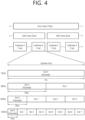
- FIG. 4 shows a structure of a radio frame of an NR, in accordance with an embodiment of the present disclosure.
- a radio frame may be used for performing uplink and downlink transmission.
- a radio frame has a length of 10ms and may be defined to be configured of two half-frames (HFs).
- a half-frame may include five 1ms subframes (SFs).
- a subframe (SF) may be divided into one or more slots, and the number of slots within a subframe may be determined in accordance with subcarrier spacing (SCS).
- SCS subcarrier spacing
- Each slot may include 12 or 14 OFDM(A) symbols according to a cyclic prefix (CP).
- CP cyclic prefix
- each slot may include 14 symbols.
- each slot may include 12 symbols.
- a symbol may include an OFDM symbol (or CP-OFDM symbol) and a Single Carrier-FDMA (SC-FDMA) symbol (or Discrete Fourier Transform-spread-OFDM (DFT-s-OFDM) symbol).
- Table 1 shown below represents an example of a number of symbols per slot (N slot symb ), a number slots per frame (N frame,u slot ), and a number of slots per subframe (N subframe,u slot ) in accordance with an SCS configuration (u), in a case where a normal CP is used.
- Table 2 shows an example of a number of symbols per slot, a number of slots per frame, and a number of slots per subframe in accordance with the SCS, in a case where an extended CP is used.
- OFDM(A) numerologies e.g., SCS, CP length, and so on
- a (absolute time) duration (or section) of a time resource e.g., subframe, slot or TTI
- TU time unit
- multiple numerologies or SCSs for supporting diverse 5G services may be supported.
- an SCS is 15kHz
- a wide area of the conventional cellular bands may be supported, and, in case an SCS is 30kHz/60kHz a dense-urban, lower latency, wider carrier bandwidth may be supported.
- a bandwidth that is greater than 24.25GHz may be used in order to overcome phase noise.
- An NR frequency band may be defined as two different types of frequency ranges.
- the two different types of frequency ranges may be FR1 and FR2.
- the values of the frequency ranges may be changed (or varied), and, for example, the two different types of frequency ranges may be as shown below in Table 3.
- FR1 may mean a "sub 6GHz range”
- FR2 may mean an "above 6GHz range” and may also be referred to as a millimeter wave (mmW).
- mmW millimeter wave
- FR1 may include a band within a range of 410MHz to 7125MHz. More specifically, FR1 may include a frequency band of 6GHz (or 5850, 5900, 5925 MHz, and so on) and higher. For example, a frequency band of 6GHz (or 5850, 5900, 5925 MHz, and so on) and higher being included in FR1 mat include an unlicensed band. The unlicensed band may be used for diverse purposes, e.g., the unlicensed band for vehicle-specific communication (e.g., automated driving).
- SCS Corresponding frequency range Subcarrier Spacing
- FIG. 5 shows a structure of a slot of an NR frame, in accordance with an embodiment of the present disclosure.
- a slot includes a plurality of symbols in a time domain.
- one slot may include 14 symbols.
- one slot may include 12 symbols.
- one slot may include 7 symbols.
- one slot may include 6 symbols.
- a carrier includes a plurality of subcarriers in a frequency domain.
- a Resource Block (RB) may be defined as a plurality of consecutive subcarriers (e.g., 12 subcarriers) in the frequency domain.
- a Bandwidth Part (BWP) may be defined as a plurality of consecutive (Physical) Resource Blocks ((P)RBs) in the frequency domain, and the BWP may correspond to one numerology (e.g., SCS, CP length, and so on).
- a carrier may include a maximum of N number BWPs (e.g., 5 BWPs). Data communication may be performed via an activated BWP.
- Each element may be referred to as a Resource Element (RE) within a resource grid and one complex symbol may be mapped to each element.
- RE Resource Element
- a radio interface between a UE and a UE or a radio interface between a UE and a network may be comprise a first layer, an L2 layer, and an L3 layer.
- layer 1 may mean a physical layer.
- the L2 layer may mean at least one of a MAC layer, an RLC layer, a PDCP layer, or an SDAP layer.
- the L3 layer may mean an RRC layer.
- V2X or SL communication will be described.
- FIG. 6 shows a UE performing V2X or SL communication, in accordance with an embodiment of the present disclosure.
- the embodiment of FIG. 6 may be combined with various embodiments of the present disclosure.
- the term 'UE' may generally imply a UE of a user.
- the BS may also be regarded as a sort of the UE.
- a UE 1 may be a first apparatus 100
- a UE 2 may be a second apparatus 200.
- the UE 1 may select a resource unit corresponding to a specific resource in a resource pool which implies a set of series of resources.
- the UE 1 may transmit an SL signal by using the resource unit.
- a resource pool in which the UE 1 is capable of transmitting a signal may be configured to the UE 2 which is a receiving UE, and the signal of the UE 1 may be detected in the resource pool.
- the BS may inform the UE 1 of the resource pool. Otherwise, if the UE 1 is out of the connectivity range of the BS, another UE may inform the UE 1 of the resource pool, or the UE 1 may use a pre-configured resource pool.
- the resource pool may be configured in unit of a plurality of resources, and each UE may select a unit of one or a plurality of resources to use it in SL signal transmission thereof.
- Resource pools can be subdivided into several types. For example, according to the content of the SL signal transmitted in each resource pool, the resource pool may be classified as follows.
- resource pools may be used according to transmission/reception properties of the SL signals. For example, even for the same SL data channel or discovery message, depending on a method for determining the transmission timing of the SL signal (e.g., whether it is transmitted at the reception time of the synchronization reference signal or transmitted by applying a certain timing advance at the reception time), resource allocation method (e.g., whether the base station assigns separate signal transmission resources to separate transmission UEs or whether separate transmission UEs select separate signal transmission resources within the resource pool), signal format (e.g., the number of symbols occupied by each SL signal in one subframe, or the number of subframes used for transmission of one SL signal), signal strength from a base station, transmit power strength of an SL UE, etc., resource pools may be divided into different resource pools.
- resource allocation method e.g., whether the base station assigns separate signal transmission resources to separate transmission UEs or whether separate transmission UEs select separate signal transmission resources within the resource pool
- signal format e.g., the number of symbols
- UE 2 may perform indirect communication with the base station through UE 1. Such indirect communication may be performed through an access link (or Uu link) between UE 1 and the base station and a sidelink between UE 1 and UE 2. UE 1 may relay signal transmission between the base station and UE 2. In this case, UE 1 may be referred to as a relay UE, and UE 2 may be referred to as a remote UE. When UE 2 performs indirect communication with a base station through UE 1, the connection between UE 2 and the base station may be referred to as an indirect connection.
- the remote UE may be within the connection range (in-coverage) of the base station.
- the remote UE may be within the connection range of the same base station as the relay UE or may be within the connection range of different base station.
- the remote UE may be outside the connection range of the base station (out-of-coverage).
- UE 2 may perform direct communication with the base station without relaying of UE 1. Such direct communication may be performed through an access link (or Uu link) between UE 2 and the base station.
- the connection between the UE 2 and the base station may be referred to as a direct connection.
- the SLSS may include a primary sidelink synchronization signal (PSSS) and a secondary sidelink synchronization signal (SSSS), as an SL-specific sequence.
- PSSS primary sidelink synchronization signal
- SSSS secondary sidelink synchronization signal
- the PSSS may be referred to as a sidelink primary synchronization signal (S-PSS)
- S-SSS sidelink secondary synchronization signal
- S-SSS sidelink secondary synchronization signal
- length-127 M-sequences may be used for the S-PSS
- length-127 gold sequences may be used for the S-SSS.
- a UE may use the S-PSS for initial signal detection and for synchronization acquisition.
- the UE may use the S-PSS and the S-SSS for acquisition of detailed synchronization and for detection of a synchronization signal ID.
- a physical sidelink broadcast channel may be a (broadcast) channel for transmitting default (system) information which must be first known by the UE before SL signal transmission/reception.
- the default information may be information related to SLSS, a duplex mode (DM), a time division duplex (TDD) uplink/downlink (UL/DL) configuration, information related to a resource pool, a type of an application related to the SLSS, a subframe offset, broadcast information, or the like.
- DM duplex mode
- TDD time division duplex
- UL/DL uplink/downlink
- a payload size of the PSBCH may be 56 bits including 24-bit cyclic redundancy check (CRC).
- the S-PSS, the S-SSS, and the PSBCH may be included in a block format (e.g., SL synchronization signal (SS)/PSBCH block, hereinafter, sidelink-synchronization signal block (S-SSB)) supporting periodical transmission.
- the S-SSB may have the same numerology (i.e., SCS and CP length) as a physical sidelink control channel (PSCCH)/physical sidelink shared channel (PSSCH) in a carrier, and a transmission bandwidth may exist within a (pre-configured sidelink (SL) BWP.
- the S-SSB may have a bandwidth of 11 resource blocks (RBs).
- the PSBCH may exist across 11 RBs.
- a frequency position of the S-SSB may be (pre-)configured. Accordingly, the UE does not have to perform hypothesis detection at frequency to discover the S-SSB in the carrier.
- the transmitting UE may transmit one or more S-SSBs to the receiving UE within one S-SSB transmission period according to the SCS.
- the number of S-SSBs that the transmitting UE transmits to the receiving UE within one S-SSB transmission period may be pre-configured or configured for the transmitting UE.
- the S-SSB transmission period may be 160 ms.
- an S-SSB transmission period of 160 ms may be supported.
- the transmitting UE may transmit one or two S-SSBs to the receiving UE within one S-SSB transmission period. For example, when the SCS is 30 kHz in FR1, the transmitting UE may transmit one or two S-SSBs to the receiving UE within one S-SSB transmission period. For example, when the SCS is 60 kHz in FR1, the transmitting UE may transmit one, two or four S-SSBs to the receiving UE within one S-SSB transmission period.
- the transmitting UE can transmit 1, 2, 4, 8, 16 or 32 S-SSBs to the receiving UE within one S-SSB transmission period.
- the transmitting UE may transmit 1, 2, 4, 8, 16, 32 or 64 S-SSBs to the receiving UE within one S-SSB transmission period.
- the structure of the S-SSB transmitted from the transmitting UE to the receiving UE may be different according to the CP type.
- the CP type may be Normal CP (NCP) or Extended CP (ECP).
- NCP Normal CP
- ECP Extended CP
- the number of symbols mapped to the PSBCH in the S-SSB transmitted by the transmitting UE may be 9 or 8.
- the CP type is ECP
- the number of symbols mapped to the PSBCH in the S-SSB transmitted by the transmitting UE may be 7 or 6.
- a PSBCH may be mapped to a first symbol in an S-SSB transmitted by a transmitting UE.
- a receiving UE receiving the S-SSB may perform an automatic gain control (AGC) operation in the first symbol interval of the S-SSB.
- AGC automatic gain control
- FIG. 7 shows a procedure of performing V2X or SL communication by a UE based on a transmission mode, in accordance with an embodiment of the present disclosure.
- the transmission mode may be called a mode or a resource allocation mode.
- the transmission mode may be called an LTE transmission mode.
- the transmission mode may be called an NR resource allocation mode.
- (a) of FIG. 7 shows a UE operation related to an LTE transmission mode 1 or an LTE transmission mode 3.
- (a) of FIG. 7 shows a UE operation related to an NR resource allocation mode 1.
- the LTE transmission mode 1 may be applied to general SL communication
- the LTE transmission mode 3 may be applied to V2X communication.
- (b) of FIG. 7 shows a UE operation related to an LTE transmission mode 2 or an LTE transmission mode 4.
- (b) of FIG. 7 shows a UE operation related to an NR resource allocation mode 2.
- a BS may schedule an SL resource to be used by the UE for SL transmission.
- the base station may perform resource scheduling to UE 1 through PDCCH (more specifically, downlink control information (DCI)), and UE 1 may perform V2X or SL communication with UE 2 according to the resource scheduling.
- DCI downlink control information
- UE 1 may transmit sidelink control information (SCI) to UE 2 through physical sidelink control channel (PSCCH), and then transmit data based on the SCI to UE 2 through physical sidelink shared channel (PSSCH).
- SCI sidelink control information
- PSCCH physical sidelink control channel
- PSSCH physical sidelink shared channel
- a UE may be provided or allocated with resources for one or more SL transmissions of one transport block (TB) from a base station through a dynamic grant.
- the base station may provide resources for transmission of the PSCCH and/or PSSCH to the UE using the dynamic grant.
- the transmitting UE may report SL hybrid automatic repeat request (HARQ) feedback received from the receiving UE to the base station.
- HARQ SL hybrid automatic repeat request
- PUCCH resources and timing for reporting SL HARQ feedback to the base station may be determined based on an indication in the PDCCH for the base station to allocate resources for SL transmission.
- DCI may indicate a slot offset between DCI reception and the first SL transmission scheduled by DCI.
- the minimum gap between the DCI scheduling the SL transmission resource and the first scheduled SL transmission resource may not be smaller than the processing time of the corresponding UE.
- a UE may be periodically provided or allocated with a resource set from a base station for a plurality of SL transmissions through a configured grant.
- the configured grant may include configured grant type 1 or configured grant type 2.
- the UE may determine a TB to transmit in each occasion indicated by the given configured grant.
- the base station may allocate SL resources to the UE on the same carrier, and may allocate SL resources to the UE on different carriers.
- the NR base station can control LTE-based SL communication.
- the NR base station may transmit NR DCI to the UE to schedule LTE SL resources.
- a new RNTI for scrambling the NR DCI may be defined.
- the UE may include an NR SL module and an LTE SL module.
- the NR SL module may convert the NR SL DCI into LTE DCI type 5A, and the NR SL module may transmit LTE DCI type 5A to the LTE SL module in units of X ms.
- the LTE SL module may apply activation and/or release to the first LTE subframe after Z ms.
- the X may be dynamically indicated using a DCI field.
- the minimum value of X may be different according to UE capability.
- a UE may report a single value according to UE capabilities.
- the X may be a positive number.
- the UE may determine an SL transmission resource within an SL resource configured by a BS/network or a pre-configured SL resource.
- the configured SL resource or the pre-configured SL resource may be a resource pool.
- the UE may autonomously select or schedule a resource for SL transmission.
- the UE may perform SL communication by autonomously selecting a resource within a configured resource pool.
- the UE may autonomously select a resource within a selective window by performing a sensing and resource (re)selection procedure.
- the sensing may be performed in unit of subchannels.
- UE 1 which has selected a resource within the resource pool, transmits SCI to UE 2 through PSCCH, and then transmits data based on the SCI to UE 2 through PSSCH.
- a UE can assist selecting SL resources for other UEs.
- the UE may receive a configured grant for SL transmission.
- a UE may schedule SL transmission of another UE.
- the UE may reserve SL resources for blind retransmission.
- a first UE may indicate the priority of SL transmission to a second UE using SCI.
- the second UE may decode the SCI, and the second UE may perform sensing and/or resource (re)selection based on the priority.
- the resource (re)selection procedure may include identifying a candidate resource in a resource selection window by a second UE and selecting a resource for (re)transmission from among the identified candidate resources.
- the resource selection window may be a time interval in which the UE selects a resource for SL transmission.
- the resource selection window may start at T1 ⁇ 0, and the resource selection window may be limited by a remaining packet delay budget of the second UE.
- the second UE may not determine the specific resource as a candidate resource.
- the SL RSRP threshold may be determined based on the priority of SL transmission indicated by the SCI received by the second UE from the first UE and the priority of the SL transmission on a resource selected by the second UE.
- the 1 SL RSRP may be measured based on SL Demodulation Reference Signal (DMRS).
- DMRS SL Demodulation Reference Signal
- one or more PSSCH DMRS patterns may be configured or previously configured in the time domain for each resource pool.
- PDSCH DMRS configuration type 1 and/or type 2 may be identical to or similar to the frequency domain pattern of PSSCH DMRS.
- the exact DMRS pattern may be indicated by SCI.
- the transmitting UE may select a specific DMRS pattern from DMRS patterns configured or previously configured for a resource pool.
- the transmitting UE may perform initial transmission of a transport block (TB) without reservation. For example, based on the sensing and resource (re)selection procedure, the transmitting UE may reserve SL resources for initial transmission of the second TB using the SCI associated with the first TB.
- TB transport block
- the UE may reserve resources for feedback-based PSSCH retransmission through signalling related to previous transmission of the same transport block (TB).
- the maximum number of SL resources reserved by one transmission including the current transmission may be 2, 3 or 4.
- the maximum number of SL resources may be the same regardless of whether HARQ feedback is enabled.
- the maximum number of HARQ (re)transmissions for one TB may be limited by configuration or preconfiguration.
- the maximum number of HARQ (re)transmissions may be up to 32.
- the configuration or preconfiguration may be for a transmission UE.
- HARQ feedback for releasing resources not used by the UE may be supported.
- a UE may use SCI to indicate one or more subchannels and/or slots used by the UE to other UEs.
- a UE may indicate to another UE one or more subchannels and/or slots reserved by the UE for PSSCH (re)transmission using SCI.
- a minimum allocation unit of SL resources may be a slot.
- the size of a subchannel may be configured or preconfigured for a UE.
- SCI sidelink control information
- Control information transmitted by a BS to a UE through a PDCCH may be referred to as downlink control information (DCI), whereas control information transmitted by the UE to another UE through a PSCCH may be referred to as SCI.
- DCI downlink control information
- SCI control information transmitted by the UE to another UE through a PSCCH
- the UE may know in advance a start symbol of the PSCCH and/or the number of symbols of the PSCCH, before decoding the PSCCH.
- the SCI may include SL scheduling information.
- the UE may transmit at least one SCI to another UE to schedule the PSSCH.
- one or more SCI formats may be defined.
- a transmitting UE may transmit the SCI to a receiving UE on the PSCCH.
- the receiving UE may decode one SCI to receive the PSSCH from the transmitting UE.
- the transmitting UE may transmit two consecutive SCIs (e.g., 2-stage SCI) to the receiving UE on the PSCCH and/or the PSSCH.
- the receiving UE may decode the two consecutive SCIs (e.g., 2-stage SCI) to receive the PSSCH from the transmitting UE.
- SCI configuration fields are divided into two groups in consideration of a (relatively) high SCI payload size
- an SCI including a first SCI configuration field group may be referred to as a first SCI or a 1st SCI
- an SCI including a second SCI configuration field group may be referred to as a second SCI or a 2nd SCI.
- the transmitting UE may transmit the first SCI to the receiving UE through the PSCCH.
- the transmitting UE may transmit the second SCI to the receiving UE on the PSCCH and/or the PSSCH.
- the second SCI may be transmitted to the receiving UE through an (independent) PSCCH, or may be transmitted in a piggyback manner together with data through the PSSCH.
- two consecutive SCIs may also be applied to different transmissions (e.g., unicast, broadcast, or groupcast).
- the transmitting UE may transmit the entirety or part of information described below to the receiving UE through the SCI.
- the transmitting UE may transmit the entirety or part of the information described below to the receiving UE through the first SCI and/or the second SCI.
- the first SCI may include information related to channel sensing.
- the receiving UE may decode the second SCI by using a PSSCH DMRS.
- a polar code used in a PDCCH may be applied to the second SCI.
- a payload size of the first SCI may be identical for unicast, groupcast, and broadcast.
- the receiving UE does not have to perform blind decoding of the second SCI.
- the first SCI may include scheduling information of the second SCI.
- the PSCCH may be replaced / substituted with at least one of the SCI, the first SCI, and/or the second SCI.
- the SCI may be replaced/substituted with at least one of the PSCCH, the first SCI, and/or the second SCI.
- the PSSCH may be replaced/substituted with the second SCI.
- FIG. 8 shows an indirect mobility procedure according to an embodiment of the present disclosure.
- mobility may include at least one of primary cell (PCell) handover (or simply handover (HO)), primary secondary cell (PSCell) addition, or PSCell change.
- PCell primary cell
- PSCell primary secondary cell
- PSCell change PSCell change.
- the embodiments described for the case of handover in this disclosure may also be applied to the case of mobility.
- indirect handover may occur in a layer 2-relay operation.
- the remote UE may establish an indirect connection to the target gNB through the relay UE while establishing a direct connection with the serving gNB.
- the remote UE may directly select a relay UE for indirect handover.
- the remote UE may select one relay UE from among several relay UEs satisfying condition(s) of the AS-layer and/or higher layer. Selection of such a relay UE may depend on the implementation of the UE.
- the base station may select a relay UE for indirect handover.
- the remote UE may report the ID/SL-RSRP information of the candidate relay UE to the serving gNB of the remote UE, and to the target relay UE. Whether to switch can be determined by the serving gNB. That is, when service continuity is considered, the remote UE may report information on neighboring candidate relay UEs to the base station, and the base station may select an appropriate relay UE from among candidate relay UEs based on the reported information. If handover is required after the base station selects the relay UE, the base station may also determine handover. An example of a procedure for the base station to select a relay UE for indirect handover is illustrated in FIG. 9 .
- FIG. 9 illustrates an example of a procedure for selecting a relay UE according to an embodiment of the present disclosure.
- the remote UE may report one or more candidate relay UE(s).
- the remote UE may filter appropriate relay UE(s) that satisfy the condition(s) of the upper layer.
- Information reported by the remote UE may include relay UE ID and/or SL RSRP information.
- the gNB may select a target relay UE and determine switching to the target relay UE.
- step S905 the gNB may perform RRC reconfiguration on the relay UE for handover of the remote UE to the relay UE.
- Step S905 is an optional step and may be omitted.
- the gNB may transmit an RRC reconfiguration message to the remote UE.
- the RRC reconfiguration message may include an ID of a target relay UE and/or target configuration for handover to the target relay UE.
- step S909 if the PC5 connection has not been established between the remote UE and the target relay UE, the remote UE may establish a PC5 connection with the target relay UE.
- step S911 the remote UE may feed back an RRC reconfiguration complete message to the gNB through the target path using the target configuration provided in the RRC reconfiguration message.
- step S913 data path switching may occur.
- a relay UE for indirect handover may be directly selected by a remote UE or selected by a base station.
- the remote UE directly selects the relay UE
- the base station selects the relay UE.
- a procedure for a remote UE to directly select a relay UE, a procedure for a base station to select a relay UE, and a procedure for a remote UE and a base station to select a relay UE together are described.
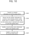
- FIG. 10 shows an example of a method performed by a wireless device according to an embodiment of the present disclosure. The steps illustrated in FIG. 10 may also be performed by the UE.
- a first wireless device may transmit, to a network, information for the first wireless device.
- the first wireless device may receive, from the network, information for a selection mode indicating whether another wireless device to establish a connection with the first wireless device is selected by the network or by the first wireless device.
- the first wireless device may identify a second wireless device determined based on the selection mode.
- the first wireless device may establish a connection with the second wireless device.
- the information for the first wireless device may comprise at least one of information indicating whether the first wireless device is a low-power device or information for a remaining battery level of the first wireless device.
- the selection mode may indicate that another wireless device to establish a connection with the first wireless device is selected by the first wireless device.
- the first wireless device may select the second wireless device based on the selection mode.
- the information for the selection mode indicating that another wireless device to establish a connection with the first wireless device is selected by the first wireless device may correspond to a configuration not to report measurement results for sidelink.
- the first wireless device may measure a sidelink signal strength.
- the first wireless device may identify one or more candidate wireless devices for which measured sidelink signal strength is higher than a configured threshold.
- the first wireless device may select the second wireless device from among the one or more wireless devices.
- the first wireless device may transmit a mobility request message to a serving cell for the first wireless device when a serving cell for the second wireless device is different from a serving cell for the first wireless device.
- the mobility request message may comprise at least one of an identifier of the second wireless device or a cell identifier of the serving cell for the second wireless device.
- the serving cell for the second wireless device may be a target cell for mobility.
- the first wireless device may receive a mobility failure message from a serving cell for the first wireless device in response to the mobility request message.
- the first wireless device may release the connection with the second wireless device.
- the first wireless device may establish a connection with a third wireless device.
- the first wireless device may receive a mobility command for mobility to the target cell from the serving cell for the first wireless device in response to the mobility request message.
- the first wireless device may apply a target cell configuration included in the mobility command. After applying the target cell configuration, the first wireless device may transmit a mobility complete message to the target cell through the second wireless device.
- the selection mode may indicate that another wireless device to establish a connection with the first wireless device is selected by the network.
- the first wireless device may receive a mobility command comprising an identifier of the second wireless device from the network.
- the information for the selection mode indicating that another wireless device to establish a connection with the first wireless device is selected by the network may correspond to a configuration not to report measurement results for sidelink.
- the first wireless device may measure a sidelink signal strength.
- the first wireless may identify one or more candidate wireless devices for which measured sidelink signal strength is higher than a configured threshold.
- the first wireless device may transmit information for a list of the one or more candidate wireless devices and a sidelink signal strength for the one or more candidate wireless devices to the network.
- the second wireless device may be selected by the network based on the sidelink signal strength from the list of the one or more candidate wireless devices.
- the first wireless device may receive a plurality of mobility commands including the mobility command, each of the plurality of mobility commands being associated with a corresponding wireless device.
- the first wireless device may select the second wireless device from among a plurality of wireless devices related to the plurality of mobility commands.
- a memory of the first wireless device may store a software code implementing instructions that, when executed by a processor for the first wireless device, perform operations comprising: transmitting, to a network, information for the first wireless device; after transmitting the information for the first wireless device to the network, receiving, from the network, information for a selection mode indicating whether another wireless device to establish a connection with the first wireless device is selected by the network or by the first wireless device; identifying a second wireless device determined based on the selection mode; and establishing a connection with the second wireless device.
- a non-transitory computer readable medium may have stored a plurality of instructions that, when executed by a processor for a first wireless device, cause the first wireless device to: transmit, to a network, information for the first wireless device; after transmitting the information for the first wireless device to the network, receive, from the network, information for a selection mode indicating whether another wireless device to establish a connection with the first wireless device is selected by the network or by the first wireless device; identify a second wireless device determined based on the selection mode; and establish a connection with the second wireless device.
- CCM computer readable medium
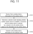
- FIG. 11 shows an example of a method performed by a base station according to an embodiment of the present disclosure.
- the base station may receive, from a wireless device, information for the wireless device.
- the base station may determine a selection mode indicating whether another wireless device to establish a connection with the wireless device is selected by a network or by the wireless device, based on the information for the wireless device.
- the base station may transmit, to the wireless device, information for the selection mode.
- the remote UE When the remote UE is not in a connected state (i.e., in an IDLE or INACTIVE state), the remote UE may select a relay UE by itself according to preconfigured criteria.
- the remote UE may transmit information for the remote UE to the base station. For example, information for the remote UE may be transmitted through a SidelinkUEInformation message. Information for the remote UE may include information indicating whether the remote UE is a power saving UE and/or information for remaining battery/power of the remote UE.
- the base station may notify whether the remote UE directly selects the relay UE or whether the base station selects the relay UE for the remote UE through RRC (re)configuration.
- the remote UE selects the relay UE by itself, the remote UE does not need to report the sidelink signal strength (e.g., SL-RSRP) and/or ID of the candidate relay UE to the base station, so power consumption of the remote UE can be reduced. Furthermore, when the remote UE itself selects the relay UE, there may be an advantage in terms of latency.
- SL-RSRP sidelink signal strength
- the remote UE needs to periodically/aperiodically report the candidate relay UE ID and/or the sidelink signal strength to the base station, so power consumption for reporting may occur.
- the base station can select a relay UE, an optimized operation is possible in terms of the entire network.
- the RRC (re)configuration information transmitted by the base station to the remote UE is information for notifying/instructing the remote UE to select a relay UE by itself (e.g., 'relay selection enable' and/or information for the selection mode).
- the remote UE receiving the RRC (re)configuration message in which 'activation of relay selection' is 'configured/indicated' can select a relay UE by itself.
- the remote UE may transmit a handover request message to the gNB.
- the remote UE may transmit the ID of the selected relay UE and/or the cell ID to which the selected relay UE belongs.
- the base station may implicitly inform the remote UE that the remote UE can or should select the relay UE by itself. For example, if a configuration not to report sidelink signal strength (SL-RSRP) measurement is included in the RRC (re)configuration message instead of the 'relay selection activation' signal, the remote UE implicitly determines that the remote UE can select the relay UE, and may select the relay UE itself.
- SL-RSRP sidelink signal strength
- a remote UE receiving an RRC (re)configuration in which 'activation of relay selection' is not 'configured/indicated' may determine that the base station selects the relay UE.
- the remote UE may report the sidelink signal strength of the candidate relay UE and/or the ID of the candidate relay UE to the base station according to a period configured by the base station.
- the remote UE may be configured to report the sidelink signal strength of the candidate relay UE and/or the ID of the candidate relay UE according to a period configured by the base station from then on.
- the remote UE implicitly determines that the gNB selects the relay UE instead, and may not select the relay UE itself.
- the base station implicitly informs the remote UE that the remote UE can or should select a relay UE by itself
- the RRC (re)configuration message comprises a configuration to measure the sidelink signal strength (SL-RSRP) of the candidate relay UE and report the sidelink signal strength (SL-RSRP) of the candidate relay UE together with the ID of the candidate relay UE
- the remote UE implicitly determines that the gNB selects the relay UE instead, and may not select the relay UE itself.
- the remote UE may select the relay UE to establish a PC5 connection before receiving the handover command.
- An operation in which the remote UE directly selects the relay UE is described with reference to FIG. 12 .
- FIG. 12 shows an example of a procedure for a remote UE to directly select a relay UE according to an embodiment of the present disclosure.
- the remote UE may measure the sidelink signal strength and select a relay UE to establish a connection with the remote UE from among candidate relay UEs having a measured signal strength higher than a (pre)configured threshold.
- the remote UE may establish a PC5 connection with the selected relay UE.
- step S1203 if the serving cell of the relay UE with which the remote UE establishes the PC5 connection is different from the serving cell of the remote UE, handover may be requested for the remote UE, and the remote UE can determine to handover to the target gNB.
- the target gNB may correspond to the serving cell of the relay UE.
- the remote UE may transmit a handover recommendation message to the gNB.
- the handover recommendation message may include at least one of an ID of a relay UE that has established a PC5 connection with the remote UE or an ID of a serving cell of the relay UE (a cell on which the relay UE camps when the relay UE is in an idle state).
- the remote UE that sent the handover recommendation message can stop performing measurements.
- the gNB may determine handover to the target gNB. Then, in step S1209, the gNB may transmit a handover request message to the target gNB, and in step S1211, the gNB may receive a handover acknowledgment message from the target gNB.
- the handover acknowledgment message may include RRC reconfiguration for handover to the target gNB.
- the gNB rejects handover, or if the gNB sends a handover request message to the target gNB but does not receive a handover acknowledgment message from the target gNB, at least one of the following operations may be performed:
- step S 1213 if handover is acknowledged by the target gNB, the serving gNB may transmit an RRC reconfiguration message received from the target gNB to the remote UE for handover to the target gNB.
- step S 1215 the remote UE may transmit an RRC reconfiguration complete message to the target gNB through the relay UE, and handover may be completed.
- the remote UE may receive the handover command and establish a PC5 connection with the relay UE.
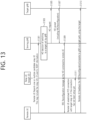
- An operation in which the serving gNB selects a relay UE is described in FIG. 13 .
- FIG. 13 shows an example of a procedure for a base station to select a relay UE according to an embodiment of the present disclosure.
- the remote UE may transmit a list of candidate relay UEs having a sidelink signal strength greater than or equal to a (pre)configured threshold to the gNB.
- the sidelink signal strength and cell ID information of the candidate relay UE may be delivered together.
- the serving gNB of the remote UE may select a relay UE from among candidate relay UEs based on the information received in step S 1301. If the cell ID of the selected relay UE is different from that of the remote UE, the serving gNB may determine handover to the target gNB.
- the target gNB may correspond to the cell ID of the selected relay UE.
- the serving gNB may transmit a handover request message to the target gNB.
- the serving gNB may receive a handover acknowledgment message from the target gNB.
- the handover acknowledgment message may include RRC reconfiguration for handover to the target gNB.
- the serving gNB may transmit an RRC reconfiguration message to the remote UE as a handover command.
- the RRC reconfiguration message may include the ID of the relay UE selected by the gNB.
- the remote UE may establish a PC5 connection with the relay UE. However, the remote UE may be rejected from establishing a PC5 connection with the relay UE due to reasons such as admission control of the relay UE. In this case, the remote UE may perform at least one of the following operations:
- the handover timer may be ignored.
- the handover timer or similar timer may be reset/stopped.
- a timer value of a handover timer or a similar timer may be set to a value greater than the legacy value by further considering an operating time for the remote UE to search for a new candidate relay UE.
- the relay UE (re)selection operation may continue.
- the remote UE may transmit an RRC reconfiguration complete message to the target gNB through the relay UE.
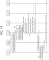
- FIG. 14 shows an example of a procedure for selecting a relay UE by a remote UE and a base station together according to an embodiment of the present disclosure.
- the remote UE may transmit information for a list of candidate relay UEs searched by the remote UE to the serving gNB.
- a cell ID of a cell to which the candidate relay UE belongs and/or information for an RRC state of the candidate relay UE may be delivered together.
- the serving gNB may determine that handover is required for the remote UE to establish a PC5 connection with the candidate relay UE.
- the serving gNB may transmit a handover request message to gNBs to which the candidate relay UE is connected (or the candidate relay UE is camping-on).
- the serving gNB must transmit a handover request message to the corresponding gNB.
- the handover request message may include an indicator notifying that the remote UE will establish a connection with a relay UE belonging to a corresponding gNB for handover (i.e., an indicator indicating activation of indirect handover).
- the serving gNB may receive a handover acknowledgment message from the gNB which each candidate relay UE is in a connected state for or camps-on.
- step S1407 the serving gNB can transmit, to a remote UE, an RRC (re)configuration message including a list of RRC (re)configurations included in the handover acknowledgment message received from the gNB in which each candidate relay UE is in a connected or camped-on state.
- Each RRC (re)configuration in the RRC reconfiguration message and/or list may include the ID of the candidate relay UE.
- Candidate relay UE IDs may be arranged according to priority in the RRC (re)configuration message.
- the remote UE may select a relay UE from the received RRC (re)configuration list.
- the remote UE may select one relay UE from among handover-capable candidate relay UEs identified in the RRC (re)configuration message received from the gNB.
- step S1411 the remote UE can establish a PC5 connection with the selected relay UE.
- the remote UE fails to establish a PC5 connection with the selected relay UE due to reasons such as access control of the relay UE, the remote UE selects another relay UE from the received RRC (re)configuration list (and/or selects another relay UE from among handover-capable candidate relay UEs identified in the RRC (re)configuration message), and attempts PC5 connection establishment the selected other relay UE.
- Step S1411 may be configured to be performed until the handover timer expires.
- the remote UE may transmit an RRC (re)configuration complete message to the target gNB through the selected relay UE.
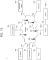
- FIG. 15 shows a communication system 1, in accordance with an embodiment of the present disclosure.
- a communication system 1 to which various embodiments of the present disclosure are applied includes wireless devices, Base Stations (BSs), and a network.
- the wireless devices represent devices performing communication using Radio Access Technology (RAT) (e.g., 5G New RAT (NR)) or Long-Term Evolution (LTE)) and may be referred to as communication/radio/5G devices.
- RAT Radio Access Technology
- the wireless devices may include, without being limited to, a robot 100a, vehicles 100b-1 and 100b-2, an extended Reality (XR) device 100c, a hand-held device 100d, a home appliance 100e, an Internet of Things (IoT) device 100f, and an Artificial Intelligence (AI) device/server 400.
- RAT Radio Access Technology
- NR 5G New RAT
- LTE Long-Term Evolution
- the wireless devices may include, without being limited to, a robot 100a, vehicles 100b-1 and 100b-2, an extended Reality (XR) device 100c, a hand-held device 100d, a home appliance 100
- the vehicles may include a vehicle having a wireless communication function, an autonomous vehicle, and a vehicle capable of performing communication between vehicles.
- the vehicles may include an Unmanned Aerial Vehicle (UAV) (e.g., a drone).
- UAV Unmanned Aerial Vehicle
- the XR device may include an Augmented Reality (AR)/Virtual Reality (VR)/Mixed Reality (MR) device and may be implemented in the form of a Head-Mounted Device (HMD), a Head-Up Display (HUD) mounted in a vehicle, a television, a smartphone, a computer, a wearable device, a home appliance device, a digital signage, a vehicle, a robot, etc.
- the hand-held device may include a smartphone, a smartpad, a wearable device (e.g., a smartwatch or a smartglasses), and a computer (e.g., a notebook).
- the home appliance may include a TV, a refrigerator, and a washing machine.
- the IoT device may include a sensor and a smartmeter.
- the BSs and the network may be implemented as wireless devices and a specific wireless device 200a may operate as a BS/network node with respect to other wireless devices.
- the wireless devices 100a to 100f may be connected to the network 300 via the BSs 200.
- An AI technology may be applied to the wireless devices 100a to 100f and the wireless devices 100a to 100f may be connected to the AI server 400 via the network 300.
- the network 300 may be configured using a 3G network, a 4G (e.g., LTE) network, or a 5G (e.g., NR) network.
- the wireless devices 100a to 100f may communicate with each other through the BSs 200/network 300, the wireless devices 100a to 100f may perform direct communication (e.g., sidelink communication) with each other without passing through the BSs/network.
- the vehicles 100b-1 and 100b-2 may perform direct communication (e.g., Vehicle-to-Vehicle (V2V)/Vehicle-to-everything (V2X) communication).
- the IoT device e.g., a sensor
- the IoT device may perform direct communication with other IoT devices (e.g., sensors) or other wireless devices 100a to 100f.
- Wireless communication/connections 150a, 150b, or 150c may be established between the wireless devices 100a to 100f/BS 200, or BS 200/BS 200.
- the wireless communication/connections may be established through various RATs (e.g., 5G NR) such as uplink/downlink communication 150a, sidelink communication 150b (or, D2D communication), or inter BS communication (e.g., relay, Integrated Access Backhaul (IAB)).
- the wireless devices and the BSs/the wireless devices may transmit/receive radio signals to/from each other through the wireless communication/connections 150a and 150b.
- the wireless communication/connections 150a and 150b may transmit/receive signals through various physical channels.
- various configuration information configuring processes various signal processing processes (e.g., channel encoding/decoding, modulation/demodulation, and resource mapping/demapping), and resource allocating processes, for transmitting/receiving radio signals, may be performed based on the various proposals of the present disclosure.
- various signal processing processes e.g., channel encoding/decoding, modulation/demodulation, and resource mapping/demapping
- resource allocating processes for transmitting/receiving radio signals
- FIG. 16 shows wireless devices, in accordance with an embodiment of the present disclosure.
- a first wireless device 100 and a second wireless device 200 may transmit radio signals through a variety of RATs (e.g., LTE and NR).
- ⁇ the first wireless device 100 and the second wireless device 200 ⁇ may correspond to ⁇ the wireless device 100x and the BS 200 ⁇ and/or ⁇ the wireless device 100x and the wireless device 100x ⁇ of FIG. 15 .
- the first wireless device 100 may include one or more processors 102 and one or more memories 104 and additionally further include one or more transceivers 106 and/or one or more antennas 108.
- the processor(s) 102 may control the memory(s) 104 and/or the transceiver(s) 106 and may be configured to implement the descriptions, functions, procedures, proposals, methods, and/or operational flowcharts disclosed in this document.
- the processor(s) 102 may process information within the memory(s) 104 to generate first information/signals and then transmit radio signals including the first information/signals through the transceiver(s) 106.
- the processor(s) 102 may receive radio signals including second information/signals through the transceiver 106 and then store information obtained by processing the second information/signals in the memory(s) 104.
- the memory(s) 104 may be connected to the processor(s) 102 and may store a variety of information related to operations of the processor(s) 102.
- the memory(s) 104 may store software code including commands for performing a part or the entirety of processes controlled by the processor(s) 102 or for performing the descriptions, functions, procedures, proposals, methods, and/or operational flowcharts disclosed in this document.
- the processor(s) 102 and the memory(s) 104 may be a part of a communication modem/circuit/chip designed to implement RAT (e.g., LTE or NR).
- the transceiver(s) 106 may be connected to the processor(s) 102 and transmit and/or receive radio signals through one or more antennas 108.
- Each of the transceiver(s) 106 may include a transmitter and/or a receiver.
- the transceiver(s) 106 may be interchangeably used with Radio Frequency (RF) unit(s).
- the wireless device may represent a communication modem/circuit/chip.
- the second wireless device 200 may include one or more processors 202 and one or more memories 204 and additionally further include one or more transceivers 206 and/or one or more antennas 208.
- the processor(s) 202 may control the memory(s) 204 and/or the transceiver(s) 206 and may be configured to implement the descriptions, functions, procedures, proposals, methods, and/or operational flowcharts disclosed in this document.
- the processor(s) 202 may process information within the memory(s) 204 to generate third information/signals and then transmit radio signals including the third information/signals through the transceiver(s) 206.
- the processor(s) 202 may receive radio signals including fourth information/signals through the transceiver(s) 106 and then store information obtained by processing the fourth information/signals in the memory(s) 204.
- the memory(s) 204 may be connected to the processor(s) 202 and may store a variety of information related to operations of the processor(s) 202.
- the memory(s) 204 may store software code including commands for performing a part or the entirety of processes controlled by the processor(s) 202 or for performing the descriptions, functions, procedures, proposals, methods, and/or operational flowcharts disclosed in this document.
- the processor(s) 202 and the memory(s) 204 may be a part of a communication modem/circuit/chip designed to implement RAT (e.g., LTE or NR).
- the transceiver(s) 206 may be connected to the processor(s) 202 and transmit and/or receive radio signals through one or more antennas 208.
- Each of the transceiver(s) 206 may include a transmitter and/or a receiver.
- the transceiver(s) 206 may be interchangeably used with RF unit(s).
- the wireless device may represent a communication modem/circuit/chip.
- One or more protocol layers may be implemented by, without being limited to, one or more processors 102 and 202.
- the one or more processors 102 and 202 may implement one or more layers (e.g., functional layers such as PHY, MAC, RLC, PDCP, RRC, and SDAP).
- the one or more processors 102 and 202 may generate one or more Protocol Data Units (PDUs) and/or one or more Service Data Unit (SDUs) according to the descriptions, functions, procedures, proposals, methods, and/or operational flowcharts disclosed in this document.
- PDUs Protocol Data Units
- SDUs Service Data Unit
- the one or more processors 102 and 202 may generate messages, control information, data, or information according to the descriptions, functions, procedures, proposals, methods, and/or operational flowcharts disclosed in this document.
- the one or more processors 102 and 202 may generate signals (e.g., baseband signals) including PDUs, SDUs, messages, control information, data, or information according to the descriptions, functions, procedures, proposals, methods, and/or operational flowcharts disclosed in this document and provide the generated signals to the one or more transceivers 106 and 206.
- the one or more processors 102 and 202 may receive the signals (e.g., baseband signals) from the one or more transceivers 106 and 206 and acquire the PDUs, SDUs, messages, control information, data, or information according to the descriptions, functions, procedures, proposals, methods, and/or operational flowcharts disclosed in this document.
- signals e.g., baseband signals
- the one or more processors 102 and 202 may be referred to as controllers, microcontrollers, microprocessors, or microcomputers.
- the one or more processors 102 and 202 may be implemented by hardware, firmware, software, or a combination thereof.
- ASICs Application Specific Integrated Circuits
- DSPs Digital Signal Processors
- DSPDs Digital Signal Processing Devices
- PLDs Programmable Logic Devices
- FPGAs Field Programmable Gate Arrays
- the descriptions, functions, procedures, proposals, methods, and/or operational flowcharts disclosed in this document may be implemented using firmware or software and the firmware or software may be configured to include the modules, procedures, or functions.
- Firmware or software configured to perform the descriptions, functions, procedures, proposals, methods, and/or operational flowcharts disclosed in this document may be included in the one or more processors 102 and 202 or stored in the one or more memories 104 and 204 so as to be driven by the one or more processors 102 and 202.
- the descriptions, functions, procedures, proposals, methods, and/or operational flowcharts disclosed in this document may be implemented using firmware or software in the form of code, commands, and/or a set of commands.
- the one or more memories 104 and 204 may be connected to the one or more processors 102 and 202 and store various types of data, signals, messages, information, programs, code, instructions, and/or commands.
- the one or more memories 104 and 204 may be configured by Read-Only Memories (ROMs), Random Access Memories (RAMs), Electrically Erasable Programmable Read-Only Memories (EPROMs), flash memories, hard drives, registers, cash memories, computer-readable storage media, and/or combinations thereof.
- the one or more memories 104 and 204 may be located at the interior and/or exterior of the one or more processors 102 and 202.
- the one or more memories 104 and 204 may be connected to the one or more processors 102 and 202 through various technologies such as wired or wireless connection.
- the one or more transceivers 106 and 206 may transmit user data, control information, and/or radio signals/channels, mentioned in the methods and/or operational flowcharts of this document, to one or more other devices.
- the one or more transceivers 106 and 206 may receive user data, control information, and/or radio signals/channels, mentioned in the descriptions, functions, procedures, proposals, methods, and/or operational flowcharts disclosed in this document, from one or more other devices.
- the one or more transceivers 106 and 206 may be connected to the one or more processors 102 and 202 and transmit and receive radio signals.
- the one or more processors 102 and 202 may perform control so that the one or more transceivers 106 and 206 may transmit user data, control information, or radio signals to one or more other devices.
- the one or more processors 102 and 202 may perform control so that the one or more transceivers 106 and 206 may receive user data, control information, or radio signals from one or more other devices.
- the one or more transceivers 106 and 206 may be connected to the one or more antennas 108 and 208 and the one or more transceivers 106 and 206 may be configured to transmit and receive user data, control information, and/or radio signals/channels, mentioned in the descriptions, functions, procedures, proposals, methods, and/or operational flowcharts disclosed in this document, through the one or more antennas 108 and 208.
- the one or more antennas may be a plurality of physical antennas or a plurality of logical antennas (e.g., antenna ports).
- the one or more transceivers 106 and 206 may convert received radio signals/channels etc.
- the one or more transceivers 106 and 206 may convert the user data, control information, radio signals/channels, etc. processed using the one or more processors 102 and 202 from the base band signals into the RF band signals.
- the one or more transceivers 106 and 206 may include (analog) oscillators and/or filters.
- the first wireless device 100 and/or one or more processors 102 may be configured to implement operations performed by the wireless device/UE in the present disclosure.
- one or more processors 102 may be configured to control one or more transceivers 106 to transmit, to a network, information for the first wireless device. After transmitting the information for the first wireless device to the network.
- the one or more processors 102 may be configured to control one or more transceivers 106 to receive, from the network, information for a selection mode indicating whether another wireless device to establish a connection with the first wireless device is selected by the network or by the first wireless device.
- the one or more processors 102 may be configured to identify a second wireless device determined based on the selection mode.
- the one or more processors 102 may be configured to establish a connection with the second wireless device.
- the second wireless device 200 and/or one or more processors 202 may be configured to implement operations performed by the base station in the present disclosure.
- one or more processors 202 may be configured to control one or more transceivers 206 to receive, from a wireless device, information for the wireless device, one or more processors 202 may be configured to determine a selection mode indicating whether another wireless device to establish a connection with the wireless device is selected by a network or by the wireless device, based on the information for the wireless device, one or more processors 202 may be configured to control the transceiver 206 to transmit, to the wireless device, information for the selection mode.
- FIG. 17 shows a signal process circuit for a transmission signal, in accordance with an embodiment of the present disclosure.
- a signal processing circuit 1000 may include scramblers 1010, modulators 1020, a layer mapper 1030, a precoder 1040, resource mappers 1050, and signal generators 1060.
- An operation/function of FIG. 17 may be performed, without being limited to, the processors 102 and 202 and/or the transceivers 106 and 206 of FIG. 16 .
- Hardware elements of FIG. 17 may be implemented by the processors 102 and 202 and/or the transceivers 106 and 206 of FIG. 16 .
- blocks 1010 to 1060 may be implemented by the processors 102 and 202 of FIG. 16 .
- the blocks 1010 to 1050 may be implemented by the processors 102 and 202 of FIG. 16 and the block 1060 may be implemented by the transceivers 106 and 206 of FIG. 16 .
- Codewords may be converted into radio signals via the signal processing circuit 1000 of FIG. 17 .
- the codewords are encoded bit sequences of information blocks.
- the information blocks may include transport blocks (e.g., a UL-SCH transport block, a DL-SCH transport block).
- the radio signals may be transmitted through various physical channels (e.g., a PUSCH and a PDSCH).
- the codewords may be converted into scrambled bit sequences by the scramblers 1010.
- Scramble sequences used for scrambling may be generated based on an initialization value, and the initialization value may include ID information of a wireless device.
- the scrambled bit sequences may be modulated to modulation symbol sequences by the modulators 1020.
- a modulation scheme may include pi/2-Binary Phase Shift Keying (pi/2-BPSK), m-Phase Shift Keying (m-PSK), and m-Quadrature Amplitude Modulation (m-QAM).
- Complex modulation symbol sequences may be mapped to one or more transport layers by the layer mapper 1030.
- Modulation symbols of each transport layer may be mapped (precoded) to corresponding antenna port(s) by the precoder 1040.
- Outputs z of the precoder 1040 may be obtained by multiplying outputs y of the layer mapper 1030 by an N ⁇ M precoding matrix W.
- N is the number of antenna ports and M is the number of transport layers.
- the precoder 1040 may perform precoding after performing transform precoding (e.g., DFT) for complex modulation symbols. Alternatively, the precoder 1040 may perform precoding without performing transform precoding.
- transform precoding e.g., DFT
- the resource mappers 1050 may map modulation symbols of each antenna port to time-frequency resources.
- the time-frequency resources may include a plurality of symbols (e.g., a CP-OFDMA symbols and DFT-s-OFDMA symbols) in the time domain and a plurality of subcarriers in the frequency domain.
- the signal generators 1060 may generate radio signals from the mapped modulation symbols and the generated radio signals may be transmitted to other devices through each antenna.
- the signal generators 1060 may include Inverse Fast Fourier Transform (IFFT) modules, Cyclic Prefix (CP) inserters, Digital-to-Analog Converters (DACs), and frequency up-converters.
- IFFT Inverse Fast Fourier Transform
- CP Cyclic Prefix
- DACs Digital-to-Analog Converters
- Signal processing procedures for a signal received in the wireless device may be configured in a reverse manner of the signal processing procedures 1010 to 1060 of FIG. 17 .
- the wireless devices e.g., 100 and 200 of FIG. 16
- the received radio signals may be converted into baseband signals through signal restorers.
- the signal restorers may include frequency downlink converters, Analog-to-Digital Converters (ADCs), CP remover, and Fast Fourier Transform (FFT) modules.
- ADCs Analog-to-Digital Converters
- FFT Fast Fourier Transform
- the baseband signals may be restored to codewords through a resource demapping procedure, a postcoding procedure, a demodulation processor, and a descrambling procedure.
- a signal processing circuit for a reception signal may include signal restorers, resource demappers, a postcoder, demodulators, descramblers, and decoders.
- FIG. 18 shows another example of a wireless device, in accordance with an embodiment of the present disclosure.
- the wireless device may be implemented in various forms according to a use-case/service (refer to FIG. 15 ).
- wireless devices 100 and 200 may correspond to the wireless devices 100 and 200 of FIG. 16 and may be configured by various elements, components, units/portions, and/or modules.
- each of the wireless devices 100 and 200 may include a communication unit 110, a control unit 120, a memory unit 130, and additional components 140.
- the communication unit may include a communication circuit 112 and transceiver(s) 114.
- the communication circuit 112 may include the one or more processors 102 and 202 and/or the one or more memories 104 and 204 of FIG. 16 .
- the transceiver(s) 114 may include the one or more transceivers 106 and 206 and/or the one or more antennas 108 and 208 of FIG. 16 .
- the control unit 120 is electrically connected to the communication unit 110, the memory 130, and the additional components 140 and controls overall operation of the wireless devices. For example, the control unit 120 may control an electric/mechanical operation of the wireless device based on programs/code/commands/information stored in the memory unit 130.
- the control unit 120 may transmit the information stored in the memory unit 130 to the exterior (e.g., other communication devices) via the communication unit 110 through a wireless/wired interface or store, in the memory unit 130, information received through the wireless/wired interface from the exterior (e.g., other communication devices) via the communication unit 110.
- the additional components 140 may be variously configured according to types of wireless devices.
- the additional components 140 may include at least one of a power unit/battery, input/output (I/O) unit, a driving unit, and a computing unit.
- the wireless device may be implemented in the form of, without being limited to, the robot (100a of FIG. 15 ), the vehicles (100b-1 and 100b-2 of FIG. 15 ), the XR device (100c of FIG. 15 ), the hand-held device (100d of FIG. 15 ), the home appliance (100e of FIG. 15 ), the IoT device (100f of FIG.
- the wireless device may be used in a mobile or fixed place according to a use-example/service.
- the entirety of the various elements, components, units/portions, and/or modules in the wireless devices 100 and 200 may be connected to each other through a wired interface or at least a part thereof may be wirelessly connected through the communication unit 110.
- the control unit 120 and the communication unit 110 may be connected by wire and the control unit 120 and first units (e.g., 130 and 140) may be wirelessly connected through the communication unit 110.
- Each element, component, unit/portion, and/or module within the wireless devices 100 and 200 may further include one or more elements.
- the control unit 120 may be configured by a set of one or more processors.
- control unit 120 may be configured by a set of a communication control processor, an application processor, an Electronic Control Unit (ECU), a graphical processing unit, and a memory control processor.
- memory 130 may be configured by a Random Access Memory (RAM), a Dynamic RAM (DRAM), a Read Only Memory (ROM)), a flash memory, a volatile memory, a non-volatile memory, and/or a combination thereof.
- RAM Random Access Memory
- DRAM Dynamic RAM
- ROM Read Only Memory
- flash memory a volatile memory
- non-volatile memory and/or a combination thereof.
- FIG. 18 An example of implementing FIG. 18 will be described in detail with reference to the drawings.
- FIG. 19 shows a hand-held device, in accordance with an embodiment of the present disclosure.
- the hand-held device may include a smartphone, a smartpad, a wearable device (e.g., a smartwatch or a smartglasses), or a portable computer (e.g., a notebook).
- the hand-held device may be referred to as a mobile station (MS), a user TERMINAL (UT), a Mobile Subscriber Station (MSS), a Subscriber Station (SS), an Advanced Mobile Station (AMS), or a Wireless UE (WT).
- MS mobile station
- MS Mobile Subscriber Station
- SS Subscriber Station
- AMS Advanced Mobile Station
- WT Wireless UE
- a hand-held device 100 may include an antenna unit 108, a communication unit 110, a control unit 120, a memory unit 130, a power supply unit 140a, an interface unit 140b, and an I/O unit 140c.
- the antenna unit 108 may be configured as a part of the communication unit 110.
- Blocks 110 to 130/140a to140c correspond to the blocks 110 to 130/140 of FIG. 18 , respectively.
- the communication unit 110 may transmit and receive signals (e.g., data and control signals) to and from other wireless devices or BSs.
- the control unit 120 may perform various operations by controlling constituent elements of the hand-held device 100.
- the control unit 120 may include an Application Processor (AP).
- the memory unit 130 may store data/parameters/programs/code/commands needed to drive the hand-held device 100.
- the memory unit 130 may store input/output data/information.
- the power supply unit 140a may supply power to the hand-held device 100 and include a wired/wireless charging circuit, a battery, etc.
- the interface unit 140b may support connection of the hand-held device 100 to other external devices.
- the interface unit 140b may include various ports (e.g., an audio I/O port and a video I/O port) for connection with external devices.
- the I/O unit 140c may input or output video information/signals, audio information/signals, data, and/or information input by a user.
- the I/O unit 140c may include a camera, a microphone, a user input unit, a display unit 140d, a speaker, and/or a haptic module.
- the I/O unit 140c may acquire information/signals (e.g., touch, text, voice, images, or video) input by a user and the acquired information/signals may be stored in the memory unit 130.
- the communication unit 110 may convert the information/signals stored in the memory into radio signals and transmit the converted radio signals to other wireless devices directly or to a BS.
- the communication unit 110 may receive radio signals from other wireless devices or the BS and then restore the received radio signals into original information/signals.
- the restored information/signals may be stored in the memory unit 130 and may be output as various types (e.g., text, voice, images, video, or haptic) through the I/O unit 140c.
- FIG. 20 shows a vehicle or an autonomous vehicle, in accordance with an embodiment of the present disclosure.
- the vehicle or autonomous vehicle may be implemented by a mobile robot, a car, a train, a manned/unmanned Aerial Vehicle (AV), a ship, etc.
- AV Aerial Vehicle
- a vehicle or autonomous vehicle 100 may include an antenna unit 108, a communication unit 110, a control unit 120, a driving unit 140a, a power supply unit 140b, a sensor unit 140c, and an autonomous driving unit 140d.
- the antenna unit 108 may be configured as a part of the communication unit 110.
- the blocks 110/130/140a to 140d correspond to the blocks 110/130/140 of FIG. 18 , respectively.
- the communication unit 110 may transmit and receive signals (e.g., data and control signals) to and from external devices such as other vehicles, BSs (e.g., gNBs and road side units), and servers.
- the control unit 120 may perform various operations by controlling elements of the vehicle or the autonomous vehicle 100.
- the control unit 120 may include an Electronic Control Unit (ECU).
- the driving unit 140a may cause the vehicle or the autonomous vehicle 100 to drive on a road.
- the driving unit 140a may include an engine, a motor, a powertrain, a wheel, a brake, a steering device, etc.
- the power supply unit 140b may supply power to the vehicle or the autonomous vehicle 100 and include a wired/wireless charging circuit, a battery, etc.
- the sensor unit 140c may acquire a vehicle state, ambient environment information, user information, etc.
- the sensor unit 140c may include an Inertial Measurement Unit (IMU) sensor, a collision sensor, a wheel sensor, a speed sensor, a slope sensor, a weight sensor, a heading sensor, a position module, a vehicle forward/backward sensor, a battery sensor, a fuel sensor, a tire sensor, a steering sensor, a temperature sensor, a humidity sensor, an ultrasonic sensor, an illumination sensor, a pedal position sensor, etc.
- IMU Inertial Measurement Unit
- the autonomous driving unit 140d may implement technology for maintaining a lane on which a vehicle is driving, technology for automatically adjusting speed, such as adaptive cruise control, technology for autonomously driving along a determined path, technology for driving by automatically setting a path if a destination is set, and the like.
- the communication unit 110 may receive map data, traffic information data, etc. from an external server.
- the autonomous driving unit 140d may generate an autonomous driving path and a driving plan from the obtained data.
- the control unit 120 may control the driving unit 140a such that the vehicle or the autonomous vehicle 100 may move along the autonomous driving path according to the driving plan (e.g., speed/direction control).
- the communication unit 110 may aperiodically/periodically acquire recent traffic information data from the external server and acquire surrounding traffic information data from neighboring vehicles.
- the sensor unit 140c may obtain a vehicle state and/or surrounding environment information.
- the autonomous driving unit 140d may update the autonomous driving path and the driving plan based on the newly obtained data/information.
- the communication unit 110 may transfer information about a vehicle position, the autonomous driving path, and/or the driving plan to the external server.
- the external server may predict traffic information data using AI technology, etc., based on the information collected from vehicles or autonomous vehicles and provide the predicted traffic information data to the vehicles or the autonomous vehicles.
- the subject selecting a relay UE for mobility can be efficiently determined according to circumstances, and a mobility procedure to the relay UE can be optimized.
Landscapes
- Engineering & Computer Science (AREA)
- Computer Networks & Wireless Communication (AREA)
- Signal Processing (AREA)
- Mobile Radio Communication Systems (AREA)
Applications Claiming Priority (3)
| Application Number | Priority Date | Filing Date | Title |
|---|---|---|---|
| US202063104495P | 2020-10-22 | 2020-10-22 | |
| US202063111074P | 2020-11-08 | 2020-11-08 | |
| PCT/KR2021/014936 WO2022086282A1 (fr) | 2020-10-22 | 2021-10-22 | Procédé et appareil pour implémenter la mobilité dans un système de communication sans fil |
Publications (3)
| Publication Number | Publication Date |
|---|---|
| EP4236471A1 true EP4236471A1 (fr) | 2023-08-30 |
| EP4236471A4 EP4236471A4 (fr) | 2024-03-27 |
| EP4236471B1 EP4236471B1 (fr) | 2025-10-01 |
Family
ID=81289991
Family Applications (1)
| Application Number | Title | Priority Date | Filing Date |
|---|---|---|---|
| EP21883349.9A Active EP4236471B1 (fr) | 2020-10-22 | 2021-10-22 | Procédé et appareil pour implémenter la mobilité dans un système de communication sans fil |
Country Status (6)
| Country | Link |
|---|---|
| US (1) | US20230363020A1 (fr) |
| EP (1) | EP4236471B1 (fr) |
| JP (1) | JP2023546577A (fr) |
| KR (1) | KR20230092875A (fr) |
| CN (1) | CN116368862A (fr) |
| WO (1) | WO2022086282A1 (fr) |
Families Citing this family (8)
| Publication number | Priority date | Publication date | Assignee | Title |
|---|---|---|---|---|
| US12557166B2 (en) * | 2020-12-18 | 2026-02-17 | Lenovo (Beijing) Limited | Method and apparatus for path switch in a wireless communication system |
| CN115150904B (zh) * | 2021-03-30 | 2024-06-04 | 维沃移动通信有限公司 | 通信路径的切换方法、装置及终端 |
| CN117280750A (zh) * | 2021-05-10 | 2023-12-22 | 联想(北京)有限公司 | 用于ue到网络中继切换的方法及设备 |
| CN115707147A (zh) * | 2021-08-06 | 2023-02-17 | 中兴通讯股份有限公司 | 无线网络通信方法、电子设备及存储介质 |
| US12375902B2 (en) * | 2022-04-28 | 2025-07-29 | Qualcomm Incorporated | Network coordination during path switching and multi-path scenarios |
| CN117202407A (zh) * | 2022-06-01 | 2023-12-08 | 夏普株式会社 | 由用户设备执行的方法及用户设备 |
| US12294903B2 (en) * | 2022-06-30 | 2025-05-06 | Asus Technology Licensing Inc. | Method and apparatus for supporting inter-GNB direct-to-indirect path switching for UE-to-NW relay communication in a wireless communication system |
| US20250301403A1 (en) * | 2024-03-25 | 2025-09-25 | Verizon Patent And Licensing Inc. | Systems and methods for intelligent repeater offload in a radio access network |
Family Cites Families (11)
| Publication number | Priority date | Publication date | Assignee | Title |
|---|---|---|---|---|
| JP2018085545A (ja) * | 2015-03-25 | 2018-05-31 | シャープ株式会社 | 端末装置、基地局装置、通信システム、通信方法および集積回路 |
| WO2017052569A1 (fr) * | 2015-09-25 | 2017-03-30 | Nokia Solutions And Networks Oy | Lancement et sélection d'un ue de relais pour communications d2d |
| CN106686674B (zh) * | 2015-11-05 | 2019-12-13 | 索尼公司 | 无线通信系统中的电子设备和无线通信方法 |
| CN107404701A (zh) * | 2016-05-19 | 2017-11-28 | 索尼公司 | 电子装置、信息处理设备和信息处理方法 |
| WO2018010123A1 (fr) * | 2016-07-13 | 2018-01-18 | 华为技术有限公司 | Procédé de communication, dispositif réseau et dispositifs terminaux |
| CN108809897A (zh) * | 2017-04-28 | 2018-11-13 | 中兴通讯股份有限公司 | 一种中继发现及中继转发方法、设备和存储介质 |
| JP7455820B2 (ja) * | 2018-09-26 | 2024-03-26 | インターデイジタル パテント ホールディングス インコーポレイテッド | Nr-u lbt mac手順 |
| CN111436079A (zh) * | 2019-01-11 | 2020-07-21 | 华硕电脑股份有限公司 | 用于无线通信中的侧链路资源分配模式配置的方法及设备 |
| US11800599B2 (en) * | 2020-04-03 | 2023-10-24 | Electronics And Telecommunications Research Institute | Method for discovering and selecting relay user equipment in communication system |
| CN115699985B (zh) * | 2020-04-09 | 2026-03-31 | 诺基亚技术有限公司 | 新无线电(nr)侧链(sl)中监测pc5到无线电资源控制(rrc)配置过程的增强 |
| WO2022067651A1 (fr) * | 2020-09-30 | 2022-04-07 | Lenovo (Beijing) Limited | Procédés et appareils pour une procédure de resélection de relais et de gestion de transmission de données dans un scénario de relais ue-réseau |
-
2021
- 2021-10-22 US US18/028,692 patent/US20230363020A1/en active Pending
- 2021-10-22 JP JP2023523100A patent/JP2023546577A/ja active Pending
- 2021-10-22 KR KR1020237009104A patent/KR20230092875A/ko active Pending
- 2021-10-22 CN CN202180072189.3A patent/CN116368862A/zh active Pending
- 2021-10-22 WO PCT/KR2021/014936 patent/WO2022086282A1/fr not_active Ceased
- 2021-10-22 EP EP21883349.9A patent/EP4236471B1/fr active Active
Also Published As
| Publication number | Publication date |
|---|---|
| WO2022086282A1 (fr) | 2022-04-28 |
| EP4236471B1 (fr) | 2025-10-01 |
| KR20230092875A (ko) | 2023-06-26 |
| US20230363020A1 (en) | 2023-11-09 |
| JP2023546577A (ja) | 2023-11-06 |
| EP4236471A4 (fr) | 2024-03-27 |
| CN116368862A (zh) | 2023-06-30 |
Similar Documents
| Publication | Publication Date | Title |
|---|---|---|
| EP3962219B1 (fr) | Procédé et appareil permettant de planifier une pluralité de ressources dans nr v2x | |
| US11895703B2 (en) | Method and apparatus for selecting PSSCH resource in NR V2X | |
| US12096421B2 (en) | SL CSI report | |
| EP4236471B1 (fr) | Procédé et appareil pour implémenter la mobilité dans un système de communication sans fil | |
| EP3706496A1 (fr) | Transmission sci en deux étapes de v2x nr | |
| US11044066B2 (en) | Method and apparatus transmitting sidelink CSI | |
| US12137475B2 (en) | Method and device for determining sidelink resource in NR V2X | |
| EP3908068B1 (fr) | Procédé et dispositif permettant d'effectuer une communication sl lte sur la base de dci | |
| EP4277431A1 (fr) | Procédé et dispositif de traitement de transition d'état dans un système de communication sans fil | |
| US11881950B2 (en) | Method and apparatus for determining NDI value on SCI in NR V2X | |
| US12015997B2 (en) | Method and device for performing sidelink communication | |
| US11943798B2 (en) | DCI for controlling LTE sidelink communication | |
| US12395988B2 (en) | Method and apparatus for performing sensing for sidelink communication in NR V2X | |
| US11350470B2 (en) | Apparatus capability report of apparatus for performing sidelink communication | |
| EP3908074A1 (fr) | Transmission d'informations de ressources de liaison latérale de nr v2x | |
| EP3996429A1 (fr) | Procédé et appareil de transmission de s-ssb dans nr v2x | |
| EP4284095A1 (fr) | Procédé et dispositif d'attribution de ressources dans un système de communication sans fil | |
| EP4277357A1 (fr) | Procédé et appareil pour contrôle d'accès dans un système de communication sans fil | |
| EP4277355A1 (fr) | Procédé et dispositif de mesure de qualité de liaison dans un système de communication sans film | |
| EP4274351A1 (fr) | Procédé et dispositif pour l'attribution de ressources dans un système de communication sans fil | |
| US12526708B2 (en) | Method and device for connection establishment in wireless communication system | |
| EP4231767A1 (fr) | Procédé et dispositif pour la mobilité dans un système de communication sans fil |
Legal Events
| Date | Code | Title | Description |
|---|---|---|---|
| STAA | Information on the status of an ep patent application or granted ep patent |
Free format text: STATUS: THE INTERNATIONAL PUBLICATION HAS BEEN MADE |
|
| PUAI | Public reference made under article 153(3) epc to a published international application that has entered the european phase |
Free format text: ORIGINAL CODE: 0009012 |
|
| STAA | Information on the status of an ep patent application or granted ep patent |
Free format text: STATUS: REQUEST FOR EXAMINATION WAS MADE |
|
| 17P | Request for examination filed |
Effective date: 20230328 |
|
| AK | Designated contracting states |
Kind code of ref document: A1 Designated state(s): AL AT BE BG CH CY CZ DE DK EE ES FI FR GB GR HR HU IE IS IT LI LT LU LV MC MK MT NL NO PL PT RO RS SE SI SK SM TR |
|
| DAV | Request for validation of the european patent (deleted) | ||
| DAX | Request for extension of the european patent (deleted) | ||
| A4 | Supplementary search report drawn up and despatched |
Effective date: 20240223 |
|
| RIC1 | Information provided on ipc code assigned before grant |
Ipc: H04W 88/04 20090101ALN20240219BHEP Ipc: H04W 36/00 20090101ALI20240219BHEP Ipc: H04W 4/40 20180101ALI20240219BHEP Ipc: H04W 92/18 20090101ALI20240219BHEP Ipc: H04W 36/08 20090101ALI20240219BHEP Ipc: H04W 36/32 20090101ALI20240219BHEP Ipc: H04W 76/14 20180101ALI20240219BHEP Ipc: H04W 40/12 20090101ALI20240219BHEP Ipc: H04W 40/22 20090101AFI20240219BHEP |
|
| STAA | Information on the status of an ep patent application or granted ep patent |
Free format text: STATUS: EXAMINATION IS IN PROGRESS |
|
| 17Q | First examination report despatched |
Effective date: 20240912 |
|
| GRAP | Despatch of communication of intention to grant a patent |
Free format text: ORIGINAL CODE: EPIDOSNIGR1 |
|
| STAA | Information on the status of an ep patent application or granted ep patent |
Free format text: STATUS: GRANT OF PATENT IS INTENDED |
|
| INTG | Intention to grant announced |
Effective date: 20250519 |
|
| RIC1 | Information provided on ipc code assigned before grant |
Ipc: H04W 88/04 20090101ALN20250510BHEP Ipc: H04W 36/00 20090101ALI20250510BHEP Ipc: H04W 4/40 20180101ALI20250510BHEP Ipc: H04W 92/18 20090101ALI20250510BHEP Ipc: H04W 36/08 20090101ALI20250510BHEP Ipc: H04W 36/32 20090101ALI20250510BHEP Ipc: H04W 76/14 20180101ALI20250510BHEP Ipc: H04W 40/12 20090101ALI20250510BHEP Ipc: H04W 40/22 20090101AFI20250510BHEP |
|
| GRAS | Grant fee paid |
Free format text: ORIGINAL CODE: EPIDOSNIGR3 |
|
| GRAA | (expected) grant |
Free format text: ORIGINAL CODE: 0009210 |
|
| STAA | Information on the status of an ep patent application or granted ep patent |
Free format text: STATUS: THE PATENT HAS BEEN GRANTED |
|
| AK | Designated contracting states |
Kind code of ref document: B1 Designated state(s): AL AT BE BG CH CY CZ DE DK EE ES FI FR GB GR HR HU IE IS IT LI LT LU LV MC MK MT NL NO PL PT RO RS SE SI SK SM TR |
|
| REG | Reference to a national code |
Ref country code: GB Ref legal event code: FG4D Ref country code: CH Ref legal event code: F10 Free format text: ST27 STATUS EVENT CODE: U-0-0-F10-F00 (AS PROVIDED BY THE NATIONAL OFFICE) Effective date: 20251001 |
|
| REG | Reference to a national code |
Ref country code: DE Ref legal event code: R096 Ref document number: 602021039798 Country of ref document: DE |
|
| REG | Reference to a national code |
Ref country code: IE Ref legal event code: FG4D |
|
| PGFP | Annual fee paid to national office [announced via postgrant information from national office to epo] |
Ref country code: DE Payment date: 20251105 Year of fee payment: 5 |
|
| PGFP | Annual fee paid to national office [announced via postgrant information from national office to epo] |
Ref country code: GB Payment date: 20251105 Year of fee payment: 5 |
|
| PGFP | Annual fee paid to national office [announced via postgrant information from national office to epo] |
Ref country code: AT Payment date: 20260113 Year of fee payment: 5 |
|
| PGFP | Annual fee paid to national office [announced via postgrant information from national office to epo] |
Ref country code: FR Payment date: 20251031 Year of fee payment: 5 |
|
| REG | Reference to a national code |
Ref country code: NL Ref legal event code: MP Effective date: 20251001 |
|
| REG | Reference to a national code |
Ref country code: AT Ref legal event code: MK05 Ref document number: 1843904 Country of ref document: AT Kind code of ref document: T Effective date: 20251001 |
|
| PG25 | Lapsed in a contracting state [announced via postgrant information from national office to epo] |
Ref country code: NL Free format text: LAPSE BECAUSE OF FAILURE TO SUBMIT A TRANSLATION OF THE DESCRIPTION OR TO PAY THE FEE WITHIN THE PRESCRIBED TIME-LIMIT Effective date: 20251001 |
|
| PG25 | Lapsed in a contracting state [announced via postgrant information from national office to epo] |
Ref country code: ES Free format text: LAPSE BECAUSE OF FAILURE TO SUBMIT A TRANSLATION OF THE DESCRIPTION OR TO PAY THE FEE WITHIN THE PRESCRIBED TIME-LIMIT Effective date: 20251001 |
|
| REG | Reference to a national code |
Ref country code: LT Ref legal event code: MG9D |
|
| PG25 | Lapsed in a contracting state [announced via postgrant information from national office to epo] |
Ref country code: NO Free format text: LAPSE BECAUSE OF FAILURE TO SUBMIT A TRANSLATION OF THE DESCRIPTION OR TO PAY THE FEE WITHIN THE PRESCRIBED TIME-LIMIT Effective date: 20260101 |
|
| PG25 | Lapsed in a contracting state [announced via postgrant information from national office to epo] |
Ref country code: HR Free format text: LAPSE BECAUSE OF FAILURE TO SUBMIT A TRANSLATION OF THE DESCRIPTION OR TO PAY THE FEE WITHIN THE PRESCRIBED TIME-LIMIT Effective date: 20251001 Ref country code: AT Free format text: LAPSE BECAUSE OF FAILURE TO SUBMIT A TRANSLATION OF THE DESCRIPTION OR TO PAY THE FEE WITHIN THE PRESCRIBED TIME-LIMIT Effective date: 20251001 Ref country code: FI Free format text: LAPSE BECAUSE OF FAILURE TO SUBMIT A TRANSLATION OF THE DESCRIPTION OR TO PAY THE FEE WITHIN THE PRESCRIBED TIME-LIMIT Effective date: 20251001 |
|
| PG25 | Lapsed in a contracting state [announced via postgrant information from national office to epo] |
Ref country code: RS Free format text: LAPSE BECAUSE OF FAILURE TO SUBMIT A TRANSLATION OF THE DESCRIPTION OR TO PAY THE FEE WITHIN THE PRESCRIBED TIME-LIMIT Effective date: 20260101 |
|
| PG25 | Lapsed in a contracting state [announced via postgrant information from national office to epo] |
Ref country code: IS Free format text: LAPSE BECAUSE OF FAILURE TO SUBMIT A TRANSLATION OF THE DESCRIPTION OR TO PAY THE FEE WITHIN THE PRESCRIBED TIME-LIMIT Effective date: 20260201 |
|
| PG25 | Lapsed in a contracting state [announced via postgrant information from national office to epo] |
Ref country code: CZ Free format text: LAPSE BECAUSE OF FAILURE TO SUBMIT A TRANSLATION OF THE DESCRIPTION OR TO PAY THE FEE WITHIN THE PRESCRIBED TIME-LIMIT Effective date: 20251001 Ref country code: PT Free format text: LAPSE BECAUSE OF FAILURE TO SUBMIT A TRANSLATION OF THE DESCRIPTION OR TO PAY THE FEE WITHIN THE PRESCRIBED TIME-LIMIT Effective date: 20260202 |
|
| PG25 | Lapsed in a contracting state [announced via postgrant information from national office to epo] |
Ref country code: PL Free format text: LAPSE BECAUSE OF FAILURE TO SUBMIT A TRANSLATION OF THE DESCRIPTION OR TO PAY THE FEE WITHIN THE PRESCRIBED TIME-LIMIT Effective date: 20251001 |
|
| PG25 | Lapsed in a contracting state [announced via postgrant information from national office to epo] |
Ref country code: LV Free format text: LAPSE BECAUSE OF FAILURE TO SUBMIT A TRANSLATION OF THE DESCRIPTION OR TO PAY THE FEE WITHIN THE PRESCRIBED TIME-LIMIT Effective date: 20251001 |