EP4236487A1 - Commande de puissance pour des transmissions de liaison montante - Google Patents
Commande de puissance pour des transmissions de liaison montante Download PDFInfo
- Publication number
- EP4236487A1 EP4236487A1 EP21883373.9A EP21883373A EP4236487A1 EP 4236487 A1 EP4236487 A1 EP 4236487A1 EP 21883373 A EP21883373 A EP 21883373A EP 4236487 A1 EP4236487 A1 EP 4236487A1
- Authority
- EP
- European Patent Office
- Prior art keywords
- resource
- uplink
- communication device
- configuration information
- iab
- Prior art date
- Legal status (The legal status is an assumption and is not a legal conclusion. Google has not performed a legal analysis and makes no representation as to the accuracy of the status listed.)
- Pending
Links
- 230000005540 biological transmission Effects 0.000 title claims description 103
- 238000000034 method Methods 0.000 claims abstract description 121
- 238000004891 communication Methods 0.000 claims description 156
- 230000015654 memory Effects 0.000 claims description 70
- 230000008878 coupling Effects 0.000 claims description 3
- 238000010168 coupling process Methods 0.000 claims description 3
- 238000005859 coupling reaction Methods 0.000 claims description 3
- 239000010410 layer Substances 0.000 description 46
- 230000006870 function Effects 0.000 description 38
- 238000005516 engineering process Methods 0.000 description 30
- 238000013473 artificial intelligence Methods 0.000 description 23
- 238000012545 processing Methods 0.000 description 17
- 230000008569 process Effects 0.000 description 11
- 230000000694 effects Effects 0.000 description 7
- 239000000470 constituent Substances 0.000 description 6
- 238000007726 management method Methods 0.000 description 6
- 238000012546 transfer Methods 0.000 description 6
- 230000001133 acceleration Effects 0.000 description 4
- 230000000903 blocking effect Effects 0.000 description 4
- 238000010586 diagram Methods 0.000 description 4
- 238000005286 illumination Methods 0.000 description 4
- 238000001228 spectrum Methods 0.000 description 4
- 230000001413 cellular effect Effects 0.000 description 3
- 125000004122 cyclic group Chemical group 0.000 description 3
- 238000011161 development Methods 0.000 description 3
- 230000018109 developmental process Effects 0.000 description 3
- 238000005259 measurement Methods 0.000 description 3
- SQMCFUSVGSBKFK-UHFFFAOYSA-M sodium;5-(cyclohexen-1-yl)-1,5-dimethylpyrimidin-3-ide-2,4,6-trione Chemical compound [Na+].O=C1N(C)C(=O)[N-]C(=O)C1(C)C1=CCCCC1 SQMCFUSVGSBKFK-UHFFFAOYSA-M 0.000 description 3
- 241000700159 Rattus Species 0.000 description 2
- 238000004873 anchoring Methods 0.000 description 2
- 238000013461 design Methods 0.000 description 2
- 230000007774 longterm Effects 0.000 description 2
- 238000013507 mapping Methods 0.000 description 2
- 230000007246 mechanism Effects 0.000 description 2
- 238000005457 optimization Methods 0.000 description 2
- 239000004984 smart glass Substances 0.000 description 2
- 238000005406 washing Methods 0.000 description 2
- 102100022734 Acyl carrier protein, mitochondrial Human genes 0.000 description 1
- 101000678845 Homo sapiens Acyl carrier protein, mitochondrial Proteins 0.000 description 1
- 230000027311 M phase Effects 0.000 description 1
- 230000005856 abnormality Effects 0.000 description 1
- 230000003044 adaptive effect Effects 0.000 description 1
- 230000002776 aggregation Effects 0.000 description 1
- 238000004220 aggregation Methods 0.000 description 1
- 238000003491 array Methods 0.000 description 1
- 238000013528 artificial neural network Methods 0.000 description 1
- 230000003190 augmentative effect Effects 0.000 description 1
- 230000033228 biological regulation Effects 0.000 description 1
- 239000000969 carrier Substances 0.000 description 1
- 230000008859 change Effects 0.000 description 1
- 230000006835 compression Effects 0.000 description 1
- 238000007906 compression Methods 0.000 description 1
- 238000007796 conventional method Methods 0.000 description 1
- 238000012937 correction Methods 0.000 description 1
- 238000007405 data analysis Methods 0.000 description 1
- 230000001934 delay Effects 0.000 description 1
- 239000003814 drug Substances 0.000 description 1
- 239000000446 fuel Substances 0.000 description 1
- 239000002346 layers by function Substances 0.000 description 1
- 230000033001 locomotion Effects 0.000 description 1
- 238000010801 machine learning Methods 0.000 description 1
- 239000011159 matrix material Substances 0.000 description 1
- 230000000116 mitigating effect Effects 0.000 description 1
- 238000011017 operating method Methods 0.000 description 1
- 230000010363 phase shift Effects 0.000 description 1
- 238000013468 resource allocation Methods 0.000 description 1
- 230000011218 segmentation Effects 0.000 description 1
- 230000015541 sensory perception of touch Effects 0.000 description 1
- 230000008054 signal transmission Effects 0.000 description 1
- 230000011664 signaling Effects 0.000 description 1
- 230000003595 spectral effect Effects 0.000 description 1
- 230000000007 visual effect Effects 0.000 description 1
Images








Classifications
-
- H—ELECTRICITY
- H04—ELECTRIC COMMUNICATION TECHNIQUE
- H04L—TRANSMISSION OF DIGITAL INFORMATION, e.g. TELEGRAPHIC COMMUNICATION
- H04L5/00—Arrangements affording multiple use of the transmission path
- H04L5/14—Two-way operation using the same type of signal, i.e. duplex
-
- H—ELECTRICITY
- H04—ELECTRIC COMMUNICATION TECHNIQUE
- H04L—TRANSMISSION OF DIGITAL INFORMATION, e.g. TELEGRAPHIC COMMUNICATION
- H04L5/00—Arrangements affording multiple use of the transmission path
- H04L5/14—Two-way operation using the same type of signal, i.e. duplex
- H04L5/1469—Two-way operation using the same type of signal, i.e. duplex using time-sharing
-
- H—ELECTRICITY
- H04—ELECTRIC COMMUNICATION TECHNIQUE
- H04W—WIRELESS COMMUNICATION NETWORKS
- H04W52/00—Power management, e.g. Transmission Power Control [TPC] or power classes
- H04W52/04—Transmission power control [TPC]
- H04W52/06—TPC algorithms
- H04W52/14—Separate analysis of uplink or downlink
- H04W52/146—Uplink power control
-
- H—ELECTRICITY
- H04—ELECTRIC COMMUNICATION TECHNIQUE
- H04W—WIRELESS COMMUNICATION NETWORKS
- H04W52/00—Power management, e.g. Transmission Power Control [TPC] or power classes
- H04W52/04—Transmission power control [TPC]
- H04W52/18—TPC being performed according to specific parameters
- H04W52/24—TPC being performed according to specific parameters using SIR [Signal to Interference Ratio] or other wireless path parameters
- H04W52/247—TPC being performed according to specific parameters using SIR [Signal to Interference Ratio] or other wireless path parameters where the output power of a terminal is based on a path parameter sent by another terminal
-
- H—ELECTRICITY
- H04—ELECTRIC COMMUNICATION TECHNIQUE
- H04W—WIRELESS COMMUNICATION NETWORKS
- H04W52/00—Power management, e.g. Transmission Power Control [TPC] or power classes
- H04W52/04—Transmission power control [TPC]
- H04W52/18—TPC being performed according to specific parameters
- H04W52/28—TPC being performed according to specific parameters using user profile, e.g. mobile speed, priority or network state, e.g. standby, idle or non-transmission
- H04W52/288—TPC being performed according to specific parameters using user profile, e.g. mobile speed, priority or network state, e.g. standby, idle or non-transmission taking into account the usage mode, e.g. hands-free, data transmission or telephone
-
- H—ELECTRICITY
- H04—ELECTRIC COMMUNICATION TECHNIQUE
- H04W—WIRELESS COMMUNICATION NETWORKS
- H04W52/00—Power management, e.g. Transmission Power Control [TPC] or power classes
- H04W52/04—Transmission power control [TPC]
- H04W52/30—Transmission power control [TPC] using constraints in the total amount of available transmission power
- H04W52/36—Transmission power control [TPC] using constraints in the total amount of available transmission power with a discrete range or set of values, e.g. step size, ramping or offsets
- H04W52/367—Power values between minimum and maximum limits, e.g. dynamic range
-
- H—ELECTRICITY
- H04—ELECTRIC COMMUNICATION TECHNIQUE
- H04W—WIRELESS COMMUNICATION NETWORKS
- H04W72/00—Local resource management
- H04W72/04—Wireless resource allocation
- H04W72/044—Wireless resource allocation based on the type of the allocated resource
- H04W72/0446—Resources in time domain, e.g. slots or frames
-
- H—ELECTRICITY
- H04—ELECTRIC COMMUNICATION TECHNIQUE
- H04W—WIRELESS COMMUNICATION NETWORKS
- H04W72/00—Local resource management
- H04W72/20—Control channels or signalling for resource management
- H04W72/23—Control channels or signalling for resource management in the downlink direction of a wireless link, i.e. towards a terminal
-
- H—ELECTRICITY
- H04—ELECTRIC COMMUNICATION TECHNIQUE
- H04W—WIRELESS COMMUNICATION NETWORKS
- H04W84/00—Network topologies
- H04W84/02—Hierarchically pre-organised networks, e.g. paging networks, cellular networks, WLAN [Wireless Local Area Network] or WLL [Wireless Local Loop]
- H04W84/04—Large scale networks; Deep hierarchical networks
- H04W84/042—Public Land Mobile systems, e.g. cellular systems
- H04W84/047—Public Land Mobile systems, e.g. cellular systems using dedicated repeater stations
-
- H—ELECTRICITY
- H04—ELECTRIC COMMUNICATION TECHNIQUE
- H04L—TRANSMISSION OF DIGITAL INFORMATION, e.g. TELEGRAPHIC COMMUNICATION
- H04L5/00—Arrangements affording multiple use of the transmission path
- H04L5/003—Arrangements for allocating sub-channels of the transmission path
- H04L5/0048—Allocation of pilot signals, i.e. of signals known to the receiver
- H04L5/0051—Allocation of pilot signals, i.e. of signals known to the receiver of dedicated pilots, i.e. pilots destined for a single user or terminal
-
- H—ELECTRICITY
- H04—ELECTRIC COMMUNICATION TECHNIQUE
- H04W—WIRELESS COMMUNICATION NETWORKS
- H04W52/00—Power management, e.g. Transmission Power Control [TPC] or power classes
- H04W52/04—Transmission power control [TPC]
- H04W52/38—TPC being performed in particular situations
-
- H—ELECTRICITY
- H04—ELECTRIC COMMUNICATION TECHNIQUE
- H04W—WIRELESS COMMUNICATION NETWORKS
- H04W52/00—Power management, e.g. Transmission Power Control [TPC] or power classes
- H04W52/04—Transmission power control [TPC]
- H04W52/38—TPC being performed in particular situations
- H04W52/46—TPC being performed in particular situations in multi-hop networks, e.g. wireless relay networks
Definitions
- the present disclosure relates to wireless communication.
- next-generation communication As more and more communication devices require more communication capacity, there is a need for improved mobile broadband communication compared to the existing radio access technology (RAT). Further, massive machine type communications (MTC) providing various services anytime anywhere by connecting many devices and objects is one of major issues to be considered in next-generation communication. In addition, there is ongoing discussion on communication system design considering a service/terminal sensitive to reliability and latency. The introduction of next-generation radio access technology considering enhanced mobile broadband communication (eMBB), massive MTC, ultra-reliable and low latency communication (URLLC), or the like is discussed. This technology is called new RAT or NR in the present disclosure for convenience.
- eMBB enhanced mobile broadband communication
- URLLC ultra-reliable and low latency communication
- IAB integrated access and backhaul links
- the concurrent operation may mean that an operation of an IAB node MT (IAB-MT) and an operation of an IAB node DU (IAB-DU) are simultaneously performed in one IAB node.
- IAB nodes perform concurrent operations, interference may further intensify.
- the present specification proposes a power control method for an IAB node MT (IAB-MT). Furthermore, the method can be applied to a terminal/UE functionally identical to that of the IAB-MT.
- the interference level between communication devices can be reduced in a full duplex terminal/UE, SBFD/SFFD environment, etc. through various power control methods proposed in the present specification.
- Effects that can be obtained through a specific example of the present specification are not limited to the aforementioned effects.
- a or B may mean “only A”, “only B”, or “both A and B”. That is, “A or B” may be interpreted as “A and/or B” herein.
- A, B or C may mean “only A”, “only B”, “only C”, or "any combination of A, B, and C”.
- a slash (/) or a comma (,) may mean “and/or”.
- A/B may mean “A and/or B”. Therefore, “A/B” may include “only A”, “only B”, or “both A and B”.
- A, B, C may mean “A, B, or C”.
- At least one of A and B may mean “only A”, “only B”, or “both A and B”. Further, as used herein, “at least one of A or B” or “at least one of A and/or B” may be interpreted equally as “at least one of A and B”.
- At least one of A, B, and C may mean “only A”, “only B”, “only C”, or “any combination of A, B, and C”. Further, “at least one of A, B, or C” or “at least one of A, B, and/or C” may mean “at least one of A, B, and C”.
- control information may mean that a PDCCH is proposed as an example of control information. That is, control information is not limited to a PDCCH, but a PDCCH is proposed as an example of control information. Further, the expression “control information (i.e., a PDCCH)” may also mean that a PDCCH is proposed as an example of control information.
- FIG. 1 shows a wireless communication system to which the present disclosure may be applied.
- the wireless communication system may be referred to as an Evolved-UMTS Terrestrial Radio Access Network (E-UTRAN) or a Long Term Evolution (LTE)/LTE-A system.
- E-UTRAN Evolved-UMTS Terrestrial Radio Access Network
- LTE Long Term Evolution
- LTE-A Long Term Evolution
- the E-UTRAN includes at least one base station (BS) 20 which provides a control plane and a user plane to a user equipment (UE) 10.
- the UE 10 may be fixed or mobile, and may be referred to as another terminology, such as a mobile station (MS), a user terminal (UT), a subscriber station (SS), a mobile terminal (MT), a wireless device, etc.
- the BS 20 is generally a fixed station that communicates with the UE 10 and may be referred to as another terminology, such as an evolved node-B (eNB), a base transceiver system (BTS), an access point, etc.
- eNB evolved node-B
- BTS base transceiver system
- access point etc.
- the BSs 20 are interconnected by means of an X2 interface.
- the BSs 20 are also connected by means of an S1 interface to an evolved packet core (EPC) 30, more specifically, to a mobility management entity (MME) through S1-MME and to a serving gateway (S-GW) through S1-U.
- EPC evolved packet core
- MME mobility management entity
- S-GW serving gateway
- the EPC 30 includes an MME, an S-GW, and a packet data network-gateway (P-GW).
- the MME has access information of the UE or capability information of the UE, and such information is generally used for mobility management of the UE.
- the S-GW is a gateway having an E-UTRAN as an end point.
- the P-GW is a gateway having a PDN as an end point.
- Layers of a radio interface protocol between the UE and the network can be classified into a first layer (L1), a second layer (L2), and a third layer (L3) based on the lower three layers of the open system interconnection (OSI) model that is well-known in the communication system.
- a physical (PHY) layer belonging to the first layer provides an information transfer service by using a physical channel
- a radio resource control (RRC) layer belonging to the third layer serves to control a radio resource between the UE and the network.
- the RRC layer exchanges an RRC message between the UE and the BS.
- FIG. 2 is a diagram showing a wireless protocol architecture for a user plane.
- FIG. 3 is a diagram showing a wireless protocol architecture for a control plane.
- the user plane is a protocol stack for user data transmission.
- the control plane is a protocol stack for control signal transmission.
- a PHY layer provides an upper layer with an information transfer service through a physical channel.
- the PHY layer is connected to a medium access control (MAC) layer which is an upper layer of the PHY layer through a transport channel.
- MAC medium access control
- Data is transferred between the MAC layer and the PHY layer through the transport channel.
- the transport channel is classified according to how and with what characteristics data is transferred through a radio interface.
- the physical channel may be modulated according to an Orthogonal Frequency Division Multiplexing (OFDM) scheme, and use the time and frequency as radio resources.
- OFDM Orthogonal Frequency Division Multiplexing
- the functions of the MAC layer include mapping between a logical channel and a transport channel and multiplexing and demultiplexing to a transport block that is provided through a physical channel on the transport channel of a MAC Service Data Unit (SDU) that belongs to a logical channel.
- SDU MAC Service Data Unit
- the MAC layer provides service to a Radio Link Control (RLC) layer through the logical channel.
- RLC Radio Link Control
- the functions of the RLC layer include the concatenation, segmentation, and reassembly of an RLC SDU.
- QoS Quality of Service
- RB Radio Bearer
- the RLC layer provides three types of operation mode: Transparent Mode (TM), Unacknowledged Mode (UM), and Acknowledged Mode (AM).
- TM Transparent Mode
- UM Unacknowledged Mode
- AM Acknowledged Mode
- AM RLC provides error correction through an Automatic Repeat Request (ARQ).
- ARQ Automatic Repeat Request
- the RRC layer is defined only on the control plane.
- the RRC layer is related to the configuration, reconfiguration, and release of radio bearers, and is responsible for control of logical channels, transport channels, and PHY channels.
- An RB means a logical route that is provided by the first layer (PHY layer) and the second layers (MAC layer, the RLC layer, and the PDCP layer) in order to transfer data between UE and a network.
- the function of a Packet Data Convergence Protocol (PDCP) layer on the user plane includes the transfer of user data and header compression and ciphering.
- the function of the PDCP layer on the user plane further includes the transfer and encryption/integrity protection of control plane data.
- PDCP Packet Data Convergence Protocol
- What an RB is configured means a process of defining the characteristics of a wireless protocol layer and channels in order to provide specific service and configuring each detailed parameter and operating method.
- An RB can be divided into two types of a Signaling RB (SRB) and a Data RB (DRB).
- SRB Signaling RB
- DRB Data RB
- the SRB is used as a passage through which an RRC message is transmitted on the control plane
- the DRB is used as a passage through which user data is transmitted on the user plane.
- the UE If RRC connection is established between the RRC layer of UE and the RRC layer of an E-UTRAN, the UE is in the RRC connected state. If not, the UE is in the RRC idle state.
- a downlink transport channel through which data is transmitted from a network to UE includes a broadcast channel (BCH) through which system information is transmitted and a downlink shared channel (SCH) through which user traffic or control messages are transmitted. Traffic or a control message for downlink multicast or broadcast service may be transmitted through the downlink SCH, or may be transmitted through an additional downlink multicast channel (MCH).
- BCH broadcast channel
- SCH downlink shared channel
- Traffic or a control message for downlink multicast or broadcast service may be transmitted through the downlink SCH, or may be transmitted through an additional downlink multicast channel (MCH).
- MCH downlink multicast channel
- an uplink transport channel through which data is transmitted from UE to a network includes a random access channel (RACH) through which an initial control message is transmitted and an uplink shared channel (SCH) through which user traffic or control messages are transmitted.
- RACH random access channel
- SCH uplink shared channel
- Logical channels that are placed over the transport channel and that are mapped to the transport channel include a broadcast control channel (BCCH), a paging control channel (PCCH), a common control channel (CCCH), a multicast control channel (MCCH), and a multicast traffic channel (MTCH).
- BCCH broadcast control channel
- PCCH paging control channel
- CCCH common control channel
- MCCH multicast control channel
- MTCH multicast traffic channel
- the physical channel includes several OFDM symbols in the time domain and several subcarriers in the frequency domain.
- One subframe includes a plurality of OFDM symbols in the time domain.
- An RB is a resources allocation unit, and includes a plurality of OFDM symbols and a plurality of subcarriers.
- each subframe may use specific subcarriers of specific OFDM symbols (e.g., the first OFDM symbol) of the corresponding subframe for a physical downlink control channel (PDCCH), that is, an L1/L2 control channel.
- PDCCH physical downlink control channel
- a Transmission Time Interval (TTI) is a unit time for transmission, e.g., a subframe or a slot.
- new radio access technology new RAT, NR
- next generation radio access technology considering enhanced mobile broadband communication (eMBB), massive MTC (mMTC), ultrareliable and low latency communication (URLLC) is discussed.
- eMBB enhanced mobile broadband communication
- mMTC massive MTC
- URLLC ultrareliable and low latency communication
- This new technology may be called new radio access technology (new RAT or NR) in the present disclosure for convenience.
- FIG. 4 shows another wireless communication system to which the present disclosure may be applied.
- FIG. 4 shows a system architecture based on a 5G new radio access technology (NR) system.
- An entity used in the 5G NR system may absorb some or all functions of the entity (e.g., eNB, MME, S-GW) introduced in FIG. 1 (e.g., eNB, MME, S-GW).
- the entity used in the NR system may be identified in the name of "NG" to distinguish it from LTE.
- a wireless communication system includes one or more UEs 11, a next-generation RAN (NG-RAN), and a 5 th generation core network (5GC).
- the NG-RAN consists of at least one NG-RAN node.
- the NG-RAN node is an entity corresponding to the BS 20 of FIG. 1 .
- the NG-RAN node consists of at least one gNB 21 and/or at least one ng-eNB 22.
- the gNB 21 provides NR user plane and control plane protocol terminations towards the UE 11.
- the Ng-eNB 22 provides an E-UTRA user plane and a control plane protocol termination towards the UE 11.
- the 5GC includes an access and mobility management function (AMF), a user plane function (UPF), and a session management function (SMF).
- AMF access and mobility management function
- UPF user plane function
- SMF session management function
- the AMF hosts functions, such as non-access stratum (NAS) security, idle state mobility processing, and so on.
- the AMF is an entity including the conventional MMF function.
- the UPF hosts functions, such as mobility anchoring, protocol data unit (PDU) processing, and so on.
- PDU protocol data unit
- the UPF is an entity including the conventional S-GW function.
- the SMF hosts functions, such as UE Internet Protocol (IP) address allocation, PDU session control, and so on.
- IP Internet Protocol
- the gNB and the ng-eNB are interconnected through an Xn interface.
- the gNB and the ng-eNB are also connected to the 5GC through an NG interface. More specifically, the gNB and the ng-eNB are connected to the AMF through an NG-C interface, and are connected to the UPF through an NG-U interface.
- FIG. 5 illustrates a functional division between an NG-RAN and a 5GC.
- the gNB may provide functions such as an inter-cell radio resource management (Inter Cell RRM), radio bearer management (RB control), connection mobility control, radio admission control, measurement configuration & provision, dynamic resource allocation, and the like.
- the AMF may provide functions such as NAS security, idle state mobility handling, and so on.
- the UPF may provide functions such as mobility anchoring, PDU processing, and the like.
- the SMF may provide functions such as UE IP address assignment, PDU session control, and so on.
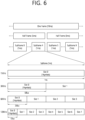
- FIG. 6 illustrates an example of a frame structure that may be applied in NR.
- a frame may be composed of 10 milliseconds (ms) and include 10 subframes each composed of 1 ms.
- uplink and downlink transmissions may be configured on a frame basis.
- a radio frame has a length of 10ms, and may be defined as two 5ms half-frames (HFs).
- the HF may be defined as five 1ms sub-frames (SFs).
- the SF is divided into one or more slots, and the number of slots in the SF depends on a subcarrier spacing (SCS).
- SCS subcarrier spacing
- Each slot includes 12 or 14 OFDM(A) symbols according to a cyclic prefix (CP). When a normal CP is used, each slot includes 14 symbols. When an extended CP is used, each slot includes 12 symbols.
- the symbol may include an OFDM symbol (or CP-OFDM symbol) and an SC-FDMA symbol (or DFT-S-OFDM symbol).
- One or a plurality of slots may be included in a subframe according to subcarrier spacings.
- the following table 2 illustrates the number of slots in a frame (N frame, ⁇ slot ), the number of slots in a subframe (N subframe, ⁇ slot ), the number of symbols in a slot (N slot symb ), and the like, according to subcarrier spacing configurations ⁇ .
- [Table 2] ⁇ N symb slot N slot frame , ⁇ N slot subframe , ⁇ 0 14 10 1 1 14 20 2 2 14 40 4 3 14 80 8 4 14 160 16
- NR supports multiple numbers (or subcarrier spacing (SCS)) to support various 5G services. For example, when the SCS is 15kHz, a wide region in the legacy cellular band is supported; and when the SCS is 30kHz/60kHz, dense urban areas, low time delay and wide carrier bandwidth are supported; and when the SCS is 60kHz or more, a bandwidth of more than 24.25GHz is supported in order to overcome phase noise.
- SCS subcarrier spacing
- the NR frequency band may be defined as two types of frequency ranges (FR1 and FR2).
- a numerical value of the frequency range may be changed and, for example, the two types of frequency ranges (FR1 and FR2) may be as shown in Table 4 below.
- FR1 may refer to "sub 6GHz range”
- FR2 may refer to "above 6GHz range” and may be called millimeter wave (mmW).
- mmW millimeter wave
- FR1 may include a band of 410 MHz to 7125 MHz as shown in Table 5 below. That is, FR1 may include a frequency band of 6 GHz (or 5850, 5900, 5925 MHz, etc.) or higher. For example, the frequency band of 6GHz (or 5850, 5900, 5925 MHz, etc.) or higher included in FR1 may include an unlicensed band. The unlicensed band may be used for various purposes, for example, for communication for a vehicle (e.g., autonomous driving). [Table 5] Frequency Range designation Corresponding frequency range Subcarrier Spacing FR1 410MHz-7125MHz 15, 30, 60kHz FR2 24250MHz-52600MHz 60, 120, 240kHz
- OFDM(A) numerologies e.g., SCS, CP length, and so on
- OFDM(A) numerologies may be differently configured between a plurality of cells integrated to one UE.
- an (absolute time) duration of a time resource e.g., SF, slot or TTI
- a time unit e.g., TU
- FIG. 7 illustrates a slot structure
- a slot includes a plurality of symbols in a time domain.
- one slot may include 14 symbols.
- one slot may include 12 symbols.
- one slot may include 7 symbols.
- one slot may include 6 symbols.
- a carrier includes a plurality of subcarriers in a frequency domain.
- a resource block (RB) may be defined as a plurality of consecutive subcarriers (e.g., 12 subcarriers) in the frequency domain.
- a bandwidth part (BWP) may be defined as a plurality of consecutive (P)RBs in the frequency domain, and the BWP may correspond to one numerology (e.g., SCS, CP length, and so on).
- the carrier may include up to N (e.g., 5) BWPs. Data communication may be performed through an activated BWP.
- Each element may be referred to as a resource element (RE) within a resource grid, and one complex symbol may be mapped thereto.
- RE resource element
- a physical downlink control channel may include one or more control channel elements (CCEs) as illustrated in the following table 6.
- CCEs control channel elements
- the PDCCH may be transmitted through a resource including 1, 2, 4, 8, or 16 CCEs.
- the CCE includes six resource element groups (REGs), and one REG includes one resource block in a frequency domain and one orthogonal frequency division multiplexing (OFDM) symbol in a time domain.
- REGs resource element groups
- OFDM orthogonal frequency division multiplexing
- a new unit called a control resource set (CORESET) may be introduced in the NR.
- the UE may receive a PDCCH in the CORESET.
- an integrated access and backhaul link (IAB) will be described. Meanwhile, hereinafter, for convenience of description, a proposed method will be described based on a new RAT (NR) system.
- NR new RAT
- the range of the system to which the proposed method is applied is expandable to other systems such as 3GPP LTE/LTE-A systems in addition to the NR system.
- IAB integrated access and backhaul links
- the node may mean a donor gNB (DgNB) or a relay node (RN).
- DgNB donor gNB
- RN relay node
- the DgNB or the donor node may be a gNB that provides a function to support backhaul to IAB nodes.
- relay node 1 which is connected to relay node 2 by a backhaul link and relaying data transmitted and received to relay node 2 is called a parent node of relay node 2, and relay node 2 is called a child node of relay node 1.
- FIG. 8 schematically illustrates an example for a network with integrated access and backhaul links (IAB).
- IAB integrated access and backhaul links
- relay nodes may multiplex access and backhaul links in the time, frequency, or space domain (i.e., beam-based operation).
- the operation of different links may operate on the same frequency or on different frequencies (which may also be referred to as 'in-band' or 'out-band' relays, respectively).
- 'in-band' or 'out-band' relays respectively.
- efficient support of out-of-band relays is important for some NR deployment scenarios, it is very important to understand the requirements of in-band operation, which implies tight interworking with access links operating on the same frequency to accommodate duplex restrictions and avoid/mitigate interference.
- OTA Over-the-air
- Legacy NR is designed to support half-duplex devices. As such, half-duplex may be supported and worthy of being targeted in an IAB scenario. Furthermore, IAB devices having a full duplex may also be considered.
- FIG. 9 shows an example of the operation of the IAB system in a standalone (SA) mode and a non-standalone (NSA) mode.
- SA standalone
- NSA non-standalone
- FIG. 9 shows an example of the operation of the UE and IAB node considering NGC in SA mode
- (b) of FIG. 9 shows an example of the operation of the IAB node considering NGC in SA mode and the UE considering EPC in NSA mode
- (c) of FIG. 9 shows an example of the operation of the UE and IAB node considering EPC in the NSA mode.
- the IAB node may operate in SA mode or NSA mode. When operating in NSA mode, the IAB node uses only the NR link for backhauling. A UE connected to the IAB node may select an operation mode different from that of the IAB node. The UE may further connect to a different type of core network than the connected IAB node. In this case, (e) DECOR ((enhanced) dedicated core network) or slicing may be used for CN selection.
- An IAB node operating in NSA mode may be connected to the same or different eNB(s). UEs operating in the NSA mode may be connected to the same or different eNB from the IAB node to which they are connected.
- FIG. 9 shows an example in consideration of NGC in SA mode and an example in consideration of EPC in NSA mode.
- the donor gNB shall schedule the entire links between the DgNB, related relay nodes and UEs.
- the DgNB should make a scheduling decision for all links by collecting traffic information from all related relay nodes, and then inform each relay node of the scheduling information.
- distributed scheduling can be performed when each relay node has a scheduling capability. Then, immediate scheduling of the uplink scheduling request of the UE is possible, and the backhaul/access link can be used more flexibly by reflecting the surrounding traffic conditions.
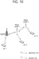
- FIG. 10 schematically illustrates an example of a configuration of access and backhaul links.
- FIG. 10 shows an example in which a backhaul link and an access link are configured when a DgNB and an IAB relay node (RN) are present.
- RN(b) and RN(e) are connecting the backhaul link
- RN(c) is connecting the backhaul link to RN(b)
- RN(d) is connecting the backhaul link to RN(c).
- the DgNB not only receives a scheduling request from the UE 1, but also receives scheduling requests from the UE 2 and UE 3. Then, the DgNB makes a scheduling decision of the two backhaul links and the three access links, and informs the scheduling results. Therefore, such centralized scheduling involves scheduling delays and causes latency problems.
- distributed scheduling can be performed if each relay node has scheduling capability. Then, immediate scheduling for the uplink scheduling request of the UE can be performed, and the backhaul/access links can be used more flexibly by reflecting the surrounding traffic situation.
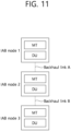
- FIG. 11 explains links and relationships between IAB nodes.
- IAB node 1 is connected to IAB node 2 through a backhaul link A.
- the IAB node 1 is the parent node of the IAB node 2
- the IAB node 2 is a child node of the IAB node 1.
- the IAB node 2 is connected to the IAB node 3 through a backhaul link B
- the IAB node 2 is a parent node of the IAB node 3 and the IAB node 3 is a child node of the IAB node 2 for the backhaul link B.
- each of the IAB nodes may perform two functions.
- One is Mobile Termination (MT), which maintains a wireless backhaul connection to an upper IAB node or donor node.
- MT Mobile Termination
- DU distributed unit
- the DU of IAB node 2 is functionally connected to the MT of IAB node 3 on the backhaul link B, and at the same time, the MT of IAB node 2 is functionally connected to the DU of IAB node 1 on the backhaul link A.
- the child link of the DU of IAB node 2 may mean the backhaul link B between the IAB node 2 and IAB node 3.
- the parent link of the MT of the IAB node 2 may mean the backhaul link A between the IAB node 2 and the IAB node 1.
- the following time domain resources may be indicated for the parent link.
- a child link has the following time resource types.
- each of the downlink time resource, uplink time resource, and flexible time resource of the DU child link may belong to one of the following two categories.
- NA time resource refers to a resource not used for communication on a DU child link.
- Each of the DL, UL, and F time resources of the DU child link may be a hard resource or a soft resource.
- the hard resource may mean resource(s) that are always available for communication on a DU child link.
- the soft resource may be resource(s) whose availability for communication on the DU child link is explicitly and/or implicitly controlled by the parent node.
- the configuration for link direction and link availability of time resources for a DU child link may be referred to as DU configuration.
- the DU configuration can be used for effective multiplexing and interference handling between IAB nodes.
- the DU configuration may be used to indicate which link is a valid link with respect to time resources between a parent link and a child link.
- only a subset of child nodes may be used for interference coordination between child nodes by configuring time resources to be used for DU operations.
- the DU configuration can be more effective when configured semi-statically.
- an IAB node MT may have three types of time resources, DL, UL, and F, for its parent link.
- resource types from the viewpoint of the IAB node DU are the UL, the DL, and the F
- configurations for availability may be classified into the NA, the hard resource, and the soft resource, respectively.
- the IAB node may receive resource configuration information, where the resource configuration information may include link direction information and availability information.
- the link direction information may inform whether the type of a specific resource is the UL, the DL, or the F
- the availability information may inform whether a specific resource is the hard resource or the soft resource.
- the link direction information may inform whether the type of a specific resource is the UL, the DL, the F, or the NA
- the availability information may inform whether a specific resource is the hard resource or the soft resource.
- new service types such as extended reality (XR), AI based service, and self-driving car are emerging. These services have characteristics in that traffic dynamically changes in both DL and UL directions and low latency is required for packet transmission. In 5G service, the traffic load will increase explosively to support these various new use cases.
- the existing semi-static or dynamic TDD UL/DL configuration has limitations such as transmission time delay and interference between operators.
- Existing FDD schemes have limitations in terms of efficient frequency resource utilization for DL/UL directions.
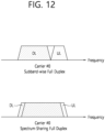
- FIG. 12 schematically illustrates an example of SB-FD and SS-FD.
- SB-FD subband-wise full duplex
- SS-FD spectrum-sharing full duplex
- FIG. 12 transmission and reception of DL and UL are performed using different frequency resources in the same carrier. That is, DL and UL have different frequency resources for the same time resource.
- transmission and reception of DL and UL are performed through the same frequency resource or overlapped frequency resources in the same carrier. That is, DL and UL may have the same or overlapping frequency resources for the same time resource.
- This full-duplex operation may be used in combination with a conventional half-duplex operation.
- a conventional half-duplex-based TDD operation only some time resources can be used for full-duplex operation.
- An SB-FD or SS-FD operation may be performed on a time resource for performing a full duplex operation.
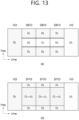
- FIG. 13 schematically illustrates an example in which a time resource operating in half duplex (HD) and a time resource operating in full duplex (FD) such as SB-FD or SS-FD coexist.
- HD half duplex
- FD full duplex
- some/partial time resources operate in SB-FD and the remaining time resources operate in HD.
- some/partial time resources operate in SS-FD and the remaining time resources operate in HD.
- the unit of time resource may be, for example, a slot or a symbol.
- some/partial frequency resources are used as DL resources and some/partial frequency resources are used as UL resources.
- all frequency resources can be used for both DL and UL.
- some frequency resources at one end or both ends of the carrier may not be used for DL and/or (and/or) UL to reduce the effect of interference (i.e., adjacent carrier interference (ACI)) from other adjacent carriers. That is, one end or both ends of the carrier may be used as a guard band that is not used for both DL and UL.
- ACI adjacent carrier interference
- one end or both ends of the carrier may be used only for DL transmission.
- a frequency resource operating in DL among all frequency resources in time resources operating in FD is referred to as a DL sub-band
- a frequency resource operating in UL is also referred to as a UL sub-band.
- the full duplex operation can be performed from both the gNB point of view and the UE point of view. That is, both the gNB and the UE can simultaneously perform transmission and reception of DL and UL using the same or different frequency resources in the same time resource.
- the gNB performs full-duplex operation, and the UE can perform half-duplex operation.
- the gNB may simultaneously transmit/receive DL and UL using the same or different frequency resources in the same time resource, but the UE performs only DL reception or UL transmission in a specific time resource. In this case, the gNB performs full duplex operation by performing DL transmission and UL reception with different UEs at the same time.
- the present specification discusses power control according to a resource type in an IAB system. Considering the simultaneous operation of the IAB system and interference caused by the IAB system, discussion on power control of the IAB system is required. In parallel with this, a method of overriding a resource configured as U/F/D by cell-specific TDD configuration according to IAB-MT specific TDD configuration may be considered. Therefore, in the present specification, IAB-MT power control according to resource types set by two methods is proposed to reduce interference caused by the IAB system.
- override for a specific resource may mean that only one configuration among the plurality of different configurations is applied when a plurality of different configurations exist for the specific resource.
- the UE may apply the UE-specific configuration rather than the cell-specific configuration to the specific resource. In this case, it may be expressed that the cell-specific configuration for the specific resource is overridden by the UE-specific configuration.
- the UE may apply the cell-specific configuration rather than UE-specific configuration to the specific resource. In this case, it may be expressed that the UE-specific configuration for the specific resource is overridden by the cell-specific configuration.
- An IAB-MT is functionally the same as or similar to a terminal/UE, and an IAB-DU is identical to or similar to a base station/gNB. Therefore, the IAB-MT described below can be interpreted as (or replaced with) a terminal/UE, and the parent IAB node or IAB-DU can be interpreted as (or replaced with) a base station/gNB. In addition, a terminal/UE described below may be interpreted as an IAB-MT, and a base station/gNB may be replaced with a parent IAB node or an IAB-DU.
- the IAB-MT may have a plurality of power classes (or maximum transmission power/configured maximum output power) by regulation/configuration for the purpose of power control for uplink transmission.
- the plurality of power classes may have different values, and a power class of a gNB, a high power UE, a normal UE, and the like may be considered.
- the maximum output power of the IAB-MT is considered in the order of P1, P2, and P3. For example, when having two power classes (gNB power class or high power UE power class and normal UE power class), the maximum output power set for the IAB-MT may consider the following.
- the IAB-MT may set or limit P1 and P2 based on the maximum output power according to the method described below.
- the terminal/UE may be allowed to set its own set maximum output power (P CMAX,f,c ) for a carrier f of serving cell c in each slot.
- the set maximum output power (P CMAX,f,c ) may be set within the following bounds.
- P EMAX,c may be a value given by one of the p-Max information element (IE) or the additionalPmax field of the NR-NS-PmaxList IE.
- P PowerClass may be maximum terminal/UE power without considering tolerance.
- P PowerClass may be one of Table 7 below for the UE power class. The remaining parameters of the above equation may refer to parameters of the 3GPP NR system.
- the following UE power classes define the maximum output power for all/entire transmission bandwidths within the channel bandwidth of an NR carrier unless otherwise specified.
- the measurement period may be at least one subframe (1 ms).
- uplink transmission power of an IAB-MT according to a resource type configured according to a cell-specific TDD configuration will be described.
- the IAB-MT may configure transmit power considering the resource configuration of the UE according to the cell-specific TDD configuration. As a default operation, the IAB-MT may perform transmission using a transmission power equal to or less than that of the UE for a resource on which the UE performs uplink transmission, and the IAB-MT may perform transmission using a transmission power equal to or less than that of the gNB for a resource on which the UE performs downlink reception. This method can reduce inter operator interference and protect reception of the gNB/transmission of the UE. To this end, the IAB-MT may consider the following according to the cases described later.
- the terminal/UE may configure a slot format per slot over multiple slots as indicated by tdd-UL-DL-ConfigurationCommon.
- the tdd-UL-DL-ConfigurationCommon may provide reference SCS configuration ⁇ ref and pattern1 by referenceSubcarrierSpacing parameter.
- pattern1 may provide a slot configuration period P[msec] by dl-UL-TransmissionPeriodicity, d slots, the number of slots with only downlink symbols by nrofDownlinkSlots, d sym , the number of downlink symbols by nrofDownlinkSymbols, u slots , the number of slots with only uplink symbols by nrofUplinkSlots, and u sym , the number of uplink symbols by nrofUplinkSymbols.
- the IAB-MT can transmit using transmit power equal to or smaller than the power class of the terminal to protect it.
- transmission may be performed using the smallest value among the maximum output powers of the IAB-MT regardless of the transmit power of the terminal.
- uplink transmission may not be performed on a resource configured as uplink cell-specifically in order not to cause interference.
- transmission power may not be set.
- the terminal may transmit using the largest value among the transmission power equal to or less than the maximum output power of the gNB/base station or the maximum output power of the IAB-MT.
- the terminal/UE determines that the resource is configured for uplink by cell-specific TDD configuration and allocates transmission power according to Case 1-1. That is, the IAB-MT can transmit using transmit power equal to or smaller than the power class of the UE. Or, as another method, the UE may allocate transmit power to the corresponding resource on the assumption that the UE is set to downlink. That is, the terminal/UE can transmit using the largest value among the transmission power equal to or less than the maximum output power of the gNB or the maximum output power of the IAB-MT.
- transmission may be performed using the largest value among transmission power equal to or less than the maximum output power of the gNB or maximum output power of the IAB-MT, and for the remaining resources, transmission may be performed using transmission power equal to or smaller than the power class of the UE.
- transmission may be performed using transmission power equal to or less than the power class of the UE, and for the remaining resources, transmission may be performed using the largest value among transmission power equal to or less than the maximum output power of the gNB or maximum output power of the IAB-MT.
- the IAB-MT when the IAB-MT performs uplink transmission on a resource configured as flexible, information related to what maximum output power is assumed for transmission may be set from the network. That is, the network may set information related to the maximum output power or power class for the flexible resource.
- the IAB-MT may set the maximum output power for the flexible resource as a default to a value predefined or set from one of the above-mentioned methods, and the maximum output power for the flexible resource from the IAB-DU / gNB / network may be set.
- the IAB-MT may be instructed with the application timing and holding time of the maximum output power for the configured flexible resource.
- the IAB-MT may be instructed only at the application time, and the application of the maximum output power may expire after a predetermined specific time.
- both the application time and the holding time may be applied as values agreed upon in advance.
- the IAB-MT may transmit using transmit power equal to or smaller than the power class of the terminal/UE.
- the IAB-MT specific TDD configuration i.e., tdd-UL-DL-ConfigurationDedicated-IAB-MT
- SFI slot format information
- the IAB-MT may transmit using transmit power equal to or smaller than the power class of the terminal/UE.
- transmit power may not be allocated. since the IAB-MT performs downlink reception, the IAB-MT may not allocate transmit power.
- the main purpose of the IAB-MT performing uplink power control by allocating transmit power/maximum output power/power class of the IAB-MT in a resource-specific manner is to control inter-cell interference of the network by using transmission power suitable for the resource direction (uplink, downlink).
- the parent IAB-DU or gNB that transmits and receives the corresponding IAB-MT also needs to set transmit power according to the resource direction.
- the IAB-DU can use all of the downlink transmission power of the gNB/IAB-DU, and this is because strong interference may occur in reception of other uplinks since it is a resource used for uplink throughout the cell. That is, the transmit power of the parent IAB-DU transmitted to and received from the IAB-MT in the above-mentioned method needs to be adjusted.
- the IAB-DU/gNB can consider the following for resources configured as uplink by UL-DL-ConfigurationCommon among the resources of the child IAB node (child IAB-MT) that transmits and receives the IAB-DU/gNB.
- the IAB-DU may not perform downlink transmission as in the existing operation.
- the IAB-DU may perform downlink transmission in the power class of the UE or the IAB-MT to protect other uplink signals since the corresponding resource may be overridden in downlink.
- the IAB-DU may perform downlink transmission in the power class of gNB/IAB-DU.
- the resource is a cell-specific uplink resource, uplink transmission of another IAB-MT/UE can be performed on the resource, so to minimize interference, the IAB-DU may perform downlink transmission in the UE/IAB-MT power class only to the corresponding child IAB node.
- the IAB-DU/gNB can consider the following for resources configured as downlink by UL-DL-ConfigurationCommon among the resources of the child IAB node (child IAB-MT) that transmits and receives the IAB-DU/gNB.
- the IAB-DU may perform downlink transmission with downlink transmission power as in the conventional operation.
- the IAB-DU may perform downlink transmission in the power class of the UE or the IAB-MT.
- the IAB-DU may not perform downlink transmission to the child IAB node or may perform downlink transmission in the power class of UE/IAB-MT.
- the IAB-DU may perform downlink transmission in the corresponding time resource to all its child IAB nodes in the power class of UE/IAB-MT.
- the above method assumes that the following proposed scheme related to TDD configuration of IAB-MT is introduced.
- resource directions set to downlink or uplink with cell-specific TDD configuration other than a flexible resource cannot be overridden in other directions by IAB-MT-specific TDD configuration.
- IAB-MT it may be considered to introduce such an operation for efficient simultaneous operation with IAB-DU. Therefore, the method described below for the TDD configuration method of the IAB-MT is proposed.
- the override method may give priority to preventing the IAB-MT from transmitting with the same or similar transmission power as that of the gNB for a period in which another terminal/UE performs an uplink operation.
- resources configured for downlink by cell-specific TDD configuration i.e., UL-DL-ConfigurationCommon
- IAB-MT specific TDD configuration i.e., tdd-UL-DL-ConfigurationDedicated-IAB-MT.
- resources configured for uplink by cell-specific TDD configuration cannot be overridden in another resource direction by IAB-MT-specific TDD configuration.
- resources configured for uplink by cell-specific TDD configuration may be overridden only in a flexible.
- the resource configured as uplink by the cell-specific TDD configuration are resource used by other terminals/UEs for uplink, if the IAB-MT transmits in this resource with a higher transmit power than a normal UE, such as the power class of the gNB, interference may occur when the gNB receives the uplink signal of the UE.
- the IAB-MT can perform resource override according to the resource change method configured in the cell-specific TDD configuration according to the IAB-MT specific TDD configuration, and the IAB-MT can allocate transmit power according to a method for suggesting uplink transmit power of the IAB-MT according to the resource type set according to the cell-specific TDD configuration, so that the uplink operation of the terminal can be protected by adjusting the transmission power similarly to that of the terminal for the period in which the terminal performs the uplink operation or the period in which the probability of performing the uplink operation is high.
- Maximum output power information applied to each time resource domain of the IAB-MT may be set. Specifically, the following methods may be used.
- the network may set a time resource region to which P2 (or P1) is applied as maximum output power to the IAB-MT.
- the IAB-MT may determine uplink transmission power by determining P2 (or P1) as the maximum output power in the corresponding time resource and determining P1 (or P2) as the maximum output power in the remaining time resource.
- maximum output power applied to the uplink resource may be configured together.
- the uplink resource is configured in a specific slot using IAB-MT specific TDD configuration (i.e., tdd-UL-DL-ConfigurationDedicated-IAB-MT)
- maximum output power applied for transmission in the uplink resource of the corresponding slot may be set together.
- the maximum output power may be indicated/informed using a method such as directly indicating/informing the maximum output power value or indicating/informing power class information.
- the IAB-MT may apply the maximum output power value according to the maximum output power mentioned in a method for suggesting uplink transmission power of an IAB-MT according to a resource type configured according to the cell-specific TDD configuration and a method of changing resources configured in cell-specific TDD configuration according to the IAB-MT specific TDD configuration as a default value. That is, the IAB-MT expects the maximum output power to be set according to the time resource, but if the maximum output power is not set, the IAB-MT may apply the maximum output power according to the TDD configuration.
- the IAB-MT may use the aforementioned maximum output power information to determine transmit power to be applied so as not to exceed the maximum output power when performing uplink transmission in the corresponding uplink resource.
- the IAB-DU/network When the IAB-DU/network schedules/configures transmission of an uplink signal/channel to the IAB-MT, it may set information on maximum output power applied to transmission of the corresponding uplink signal/channel. That is, scheduling/configuration of uplink signals/channels and maximum output power for the uplink signals/channels may be explicitly/implicitly set simultaneously.
- the IAB-MT may apply the maximum output power value according to the maximum output power mentioned in a method for suggesting uplink transmission power of an IAB-MT according to a resource type configured according to the cell-specific TDD configuration and a method of changing resources configured in cell-specific TDD configuration according to the IAB-MT specific TDD configuration as a default value. That is, the IAB-MT expects the maximum output power to be set according to the scheduling/configuration, but if the maximum output power is not set, the IAB-MT may apply the maximum output power according to the TDD configuration.
- the above-described methods may consider the following network conditions depending on whether the gNB or the UE operates in full duplex mode.
- the gNB may be replaced by the parent IAB-DU and the UE may be replaced by the IAB-MT.
- the parent IAB node or parent IAB-DU in the above method may be replaced by the gNB, and the IAB-MT or IAB node may be replaced by the UE.
- the full duplex operation of the UE may consider two things. First, it may be considered to perform a full duplex operation in a time resource explicitly indicated in a specific direction (i.e., uplink, downlink, flexible or new slot format for supporting a full duplex UE, etc.) by a cell-specific resource. In this case, the full duplex UE may expect to set the maximum output power according to the time resource of the maximum output power according to the above-mentioned time resource. That is, with respect to the time resource for simultaneous transmission/reception of a full-duplex UE and the time resource transmitted by the UE in a half-duplex operation, the UE may be expected to be set to different maximum output powers.
- a time resource explicitly indicated in a specific direction i.e., uplink, downlink, flexible or new slot format for supporting a full duplex UE, etc.
- the full duplex UE may expect to set the maximum output power according to the time resource of the maximum output power according to the above-mentioned time resource
- the cell-specific resource is cell common information
- a method in which the gNB indicates the resource direction to an uplink, a downlink, or a flexible time resource as in the conventional method, and then overrides this with a UE-specific resource to indicate a time resource in which the full duplex UE can transmit/receive at the same time may be considered.
- the UE may receive the maximum output power set according to the resource type in a method similar to the Case 1-1, Case 1-2, and Case 1-3 described above.
- Two cases may be considered for full duplex of gNB.
- the case of a gNB performing a full duplex operation in all operating bands and the case of performing a full duplex operation in some bands or an uplink band and a downlink band adjacent to each other may be considered. That is, SBFD and SFFD mentioned in FIG. 13 may be considered.
- SBFD and SFFD two of the methods for informing/indicating the UE of the period in which the gNB performs full duplex operation may be considered.
- a method of indicating a time interval in which a gNB performs a full duplex operation as a flexible resource in cell-specific resource configuration and indicating a flexible resource for each UE as uplink or downlink may be considered.
- Second, a method of indicating all of the time intervals for performing full duplex operation in uplink or downlink in cell-specific resource configuration and then overriding them in a different direction in UE-specific resource configuration can be considered.
- the gNB may configure DDDDU (downlink-downlink-downlink-downlink-uplink) based on cell-specific configurations for a total of five slots, and the gNB may override the 2nd, 3rd, and 4th slot formats to uplink based on UE-specific resource configuration in order to indicate uplink transmission to some UEs in the cell in the time interval corresponding to the SBFD, that is, the 2nd, 3rd, and 4th slots may be considered.
- DDDDU downlink-downlink-downlink-downlink-uplink
- a method in which the gNB may configure DUUUU (downlink-uplink-uplink-uplink) based on cell-specific configurations for a total of five slots, and the gNB may override the 2nd, 3rd, and 4th slot formats to downlink based on UE-specific resource configuration in order to indicate some UEs in the cell to receive downlink in the time interval corresponding to SBFD, that is, in the 2nd, 3rd, and 4th slots may be considered.
- the UE may identify the time resource in which the gNB performs downlink (DL) transmission in half duplex (HD), the time resource for the gNB to perform SBFD (or SFFD), such as the 2nd, 3rd, and 4th slots, and the time resource for gNB to perform uplink (UL) reception in half duplex.
- the UE may consider being allocated different maximum output powers for resource type 1 and resource type 2.
- the gNB may set the maximum output power of the UE to be smaller than that of resource type 2 in the time resource of resource type 1 for the purpose of suppressing UE-to-UE interference. Through this, reception interference can be suppressed from the perspective of a UE performing downlink reception in resource type 1.
- the gNB may set the maximum output power of the UE to be greater than resource type 2 in the time resource of resource type 1 for the decoding performance of the receiving end of the gNB due to self-interference cancellation performance, etc.
- the gNB may indicate the difference in maximum output power according to the resource type, that is, the difference between the maximum output power in resource type 1 and resource type 2 to the UE by prior appointment or agreement, or the gNB may indicate the difference through radio resource control (RRC)/medium access control-control element (MAC-CE)/DCI.
- RRC radio resource control
- MAC-CE medium access control-control element
- FIG. 14 is a flowchart of an example of an uplink transmission method of a first communication device according to some implementations of the present specification.
- the first communication device receives resource configuration information from the second communication device (S1410).
- the resource configuration information may inform/indicate a location of a downlink resource, a flexible resource, and an uplink resource, and maximum output power allocated to the uplink resource.
- the first communication device performs uplink transmission to the second communication device through the uplink resource based on the resource configuration information (S1420).
- transmit power of the uplink transmission may be less than or equal to the maximum output power.
- the resource configuration information may include information on the resource direction (uplink, downlink, flexible) of the time resource in the first slot and information on the first maximum output power configured/allocated for the uplink resource in the first slot.
- the resource configuration information may include information on the resource direction (uplink, downlink, flexible) of the time resource in the second slot and information on the first maximum output power configured/allocated for the uplink resource in the second slot.
- the first communication device may perform uplink transmission for the second communication device based on the first maximum output power through uplink resource in the first slot.
- the first communication device may perform uplink transmission for the second communication device based on the second maximum output power through uplink resource in the second slot.
- the value of the first maximum output power and the value of the second maximum output power may be different from each other. Accordingly, power control according to the time resource is possible. Meanwhile, in the above example, the case where the time resource unit is a slot has been described, but it is obvious that the method of FIG. 14 can be extended and applied to various time resource units.
- FIG. 15 is a flowchart of an example of a method of receiving an uplink signal by a second communication device according to some implementations of the present specification.
- the second communication device transmits resource configuration information to the first communication device (S1510).
- the resource configuration information may inform/indicate a location of a downlink resource, a flexible resource, and an uplink resource, and maximum output power allocated to the uplink resource.
- the second communication device receives the uplink signal from the first communication device through the uplink resource (S1520).
- transmit power of the uplink signal may be less than or equal to the maximum output power.
- the methods proposed in the present specification may be performed by at least one computer readable medium (CRM) including instructions based on being executed by at least one processor and an apparatus/device configured for controlling the UE/IAB node and for including at least one memory storing instructions and at least processor coupling the at least one memory in addition to the terminal/IAB node, wherein the CRM, wherein the at least one processor is configured for performing the methods proposed herein.
- CRM computer readable medium
- FIG. 16 shows a communication system (1), in accordance with an embodiment of the present disclosure.
- a communication system (1) to which various embodiments of the present disclosure are applied includes wireless devices, Base Stations (BSs), and a network.
- the wireless devices represent devices performing communication using Radio Access Technology (RAT) (e.g., 5G New RAT (NR)) or Long-Term Evolution (LTE)) and may be referred to as communication/radio/5G devices.
- RAT Radio Access Technology
- the wireless devices may include, without being limited to, a robot (100a), vehicles (100b-1, 100b-2), an extended Reality (XR) device (100c), a hand-held device (100d), a home appliance (100e), an Internet of Things (IoT) device (100f), and an Artificial Intelligence (AI) device/server (400).
- RAT Radio Access Technology
- NR 5G New RAT
- LTE Long-Term Evolution
- the wireless devices may include, without being limited to, a robot (100a), vehicles (100b-1, 100b-2), an extended Reality (XR) device (100c), a hand-
- the vehicles may include a vehicle having a wireless communication function, an autonomous vehicle, and a vehicle capable of performing communication between vehicles.
- the vehicles may include an Unmanned Aerial Vehicle (UAV) (e.g., a drone).
- UAV Unmanned Aerial Vehicle
- the XR device may include an Augmented Reality (AR)/Virtual Reality (VR)/Mixed Reality (MR) device and may be implemented in the form of a Head-Mounted Device (HMD), a Head-Up Display (HUD) mounted in a vehicle, a television, a smartphone, a computer, a wearable device, a home appliance device, a digital signage, a vehicle, a robot, and so on.
- the hand-held device may include a smartphone, a smartpad, a wearable device (e.g., a smartwatch or a smartglasses), and a computer (e.g., a notebook).
- the home appliance may include a TV, a refrigerator, and a washing machine.
- the IoT device may include a sensor and a smartmeter.
- the BSs and the network may be implemented as wireless devices and a specific wireless device (200a) may operate as a BS/network node with respect to other wireless devices.
- the wireless communication technology implemented in the wireless device of the present specification may include a narrowband Internet of Things for low-power communication as well as LTE, NR, and 6G.
- the NB-IoT technology may be an example of a Low Power Wide Area Network (LPWAN) technology.
- LPWAN Low Power Wide Area Network
- the wireless communication technology implemented in the wireless device of the present specification may perform communication based on LTE-M technology.
- the LTE-M technology may be an example of an LPWAN technology, and may be called by various names such as enhanced machine type communication (eMTC).
- eMTC enhanced machine type communication
- LTE-M technology may be implemented in at least one of various standards such as 1) LTE CAT 0, 2) LTE Cat M1, 3) LTE Cat M2, 4) LTE non-BL (non-Bandwidth Limited), 5) LTE-MTC, 6) LTE Machine Type Communication, and/or 7) LTE M, and is not limited to the above-described name.
- the wireless communication technology implemented in the wireless device of the present specification may include at least one of ZigBee, Bluetooth, and Low Power Wide Area Network (LPWAN) in consideration of low-power communication, and is not limited to the above-described name.
- the ZigBee technology can create PAN (personal area networks) related to small/low-power digital communication based on various standards such as IEEE 802.15.4, and can be called by various names.
- the wireless devices (100a ⁇ 100f) may be connected to the network (300) via the BSs (200).
- An AI technology may be applied to the wireless devices (100a ⁇ 100f) and the wireless devices (100a ⁇ 100f) may be connected to the AI server (400) via the network (300).
- the network (300) may be configured using a 3G network, a 4G (e.g., LTE) network, or a 5G (e.g., NR) network.
- the wireless devices (100a ⁇ 100f) may communicate with each other through the BSs (200)/network (300)
- the wireless devices (100a ⁇ 100f) may perform direct communication (e.g., sidelink communication) with each other without passing through the BSs/network.
- the vehicles (100b-1, 100b-2) may perform direct communication (e.g., Vehicle-to-Vehicle (V2V)/Vehicle-to-everything (V2X) communication).
- the IoT device e.g., a sensor
- the IoT device may perform direct communication with other IoT devices (e.g., sensors) or other wireless devices (100a ⁇ 100f).
- Wireless communication/connections may be established between the wireless devices (100a ⁇ 100f)/BS (200), or BS (200)/BS (200).
- the wireless communication/connections may be established through various RATs (e.g., 5G NR) such as uplink/downlink communication (150a), sidelink communication (150b) (or, D2D communication), or inter BS communication (e.g. relay, Integrated Access Backhaul (IAB)).
- the wireless devices and the BSs/the wireless devices may transmit/receive radio signals to/from each other through the wireless communication/connections (150a, 150b).
- the wireless communication/connections (150a, 150b) may transmit/receive signals through various physical channels.
- various configuration information configuring processes various signal processing processes (e.g., channel encoding/decoding, modulation/demodulation, and resource mapping/demapping), and resource allocating processes, for transmitting/receiving radio signals, may be performed based on the various proposals of the present disclosure.
- various signal processing processes e.g., channel encoding/decoding, modulation/demodulation, and resource mapping/demapping
- resource allocating processes for transmitting/receiving radio signals
- FIG. 17 shows wireless devices, in accordance with an embodiment of the present disclosure.
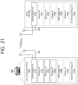
- a first wireless device (100) and a second wireless device (200) may transmit radio signals through a variety of RATs (e.g., LTE and NR).
- ⁇ the first wireless device (100) and the second wireless device (200) ⁇ may correspond to ⁇ the wireless device (100x), the BS (200) ⁇ and/or ⁇ the wireless device (100x), the wireless device (100x) ⁇ of FIG. 16 .
- the first wireless device (100) may include one or more processors (102) and one or more memories (104) and additionally further include one or more transceivers (106) and/or one or more antennas (108).
- the processor(s) (102) may control the memory(s) (104) and/or the transceiver(s) (106) and may be configured to implement the descriptions, functions, procedures, proposals, methods, and/or operational flowcharts disclosed in this document.
- the processor(s) (102) may process information within the memory(s) (104) to generate first information/signals and then transmit radio signals including the first information/signals through the transceiver(s) (106).
- the processor(s) (102) may receive radio signals including second information/signals through the transceiver (106) and then store information obtained by processing the second information/signals in the memory(s) (104).
- the memory(s) (104) may be connected to the processor(s) (102) and may store a variety of information related to operations of the processor(s) (102).
- the memory(s) (104) may store software code including commands for performing a part or the entirety of processes controlled by the processor(s) (102) or for performing the descriptions, functions, procedures, proposals, methods, and/or operational flowcharts disclosed in this document.
- the processor(s) (102) and the memory(s) (104) may be a part of a communication modem/circuit/chip designed to implement RAT (e.g., LTE or NR).
- the transceiver(s) (106) may be connected to the processor(s) (102) and transmit and/or receive radio signals through one or more antennas (108).
- Each of the transceiver(s) (106) may include a transmitter and/or a receiver.
- the transceiver(s) (106) may be interchangeably used with Radio Frequency (RF) unit(s).
- the wireless device may represent a communication modem/circuit/chip.
- the second wireless device (200) may include one or more processors (202) and one or more memories (204) and additionally further include one or more transceivers (206) and/or one or more antennas (208).
- the processor(s) (202) may control the memory(s) (204) and/or the transceiver(s) (206) and may be configured to implement the descriptions, functions, procedures, proposals, methods, and/or operational flowcharts disclosed in this document.
- the processor(s) (202) may process information within the memory(s) (204) to generate third information/signals and then transmit radio signals including the third information/signals through the transceiver(s) (206).
- the processor(s) (202) may receive radio signals including fourth information/signals through the transceiver(s) (106) and then store information obtained by processing the fourth information/signals in the memory(s) (204).
- the memory(s) (204) may be connected to the processor(s) (202) and may store a variety of information related to operations of the processor(s) (202).
- the memory(s) (204) may store software code including commands for performing a part or the entirety of processes controlled by the processor(s) (202) or for performing the descriptions, functions, procedures, proposals, methods, and/or operational flowcharts disclosed in this document.
- the processor(s) (202) and the memory(s) (204) may be a part of a communication modem/circuit/chip designed to implement RAT (e.g., LTE or NR).
- the transceiver(s) (206) may be connected to the processor(s) (202) and transmit and/or receive radio signals through one or more antennas (208).
- Each of the transceiver(s) (206) may include a transmitter and/or a receiver.
- the transceiver(s) (206) may be interchangeably used with RF unit(s).
- the wireless device may represent a communication modem/circuit/chip.
- One or more protocol layers may be implemented by, without being limited to, one or more processors (102, 202).
- the one or more processors (102, 202) may implement one or more layers (e.g., functional layers such as PHY, MAC, RLC, PDCP, RRC, and SDAP).
- the one or more processors (102, 202) may generate one or more Protocol Data Units (PDUs) and/or one or more Service Data Unit (SDUs) according to the descriptions, functions, procedures, proposals, methods, and/or operational flowcharts disclosed in this document.
- PDUs Protocol Data Units
- SDUs Service Data Unit
- the one or more processors (102, 202) may generate messages, control information, data, or information according to the descriptions, functions, procedures, proposals, methods, and/or operational flowcharts disclosed in this document.
- the one or more processors (102, 202) may generate signals (e.g., baseband signals) including PDUs, SDUs, messages, control information, data, or information according to the descriptions, functions, procedures, proposals, methods, and/or operational flowcharts disclosed in this document and provide the generated signals to the one or more transceivers (106, 206).
- the one or more processors (102, 202) may receive the signals (e.g., baseband signals) from the one or more transceivers (106, 206) and obtain the PDUs, SDUs, messages, control information, data, or information according to the descriptions, functions, procedures, proposals, methods, and/or operational flowcharts disclosed in this document.
- signals e.g., baseband signals
- transceivers e.g., baseband signals
- the one or more processors (102, 202) may be referred to as controllers, microcontrollers, microprocessors, or microcomputers.
- the one or more processors (102, 202) may be implemented by hardware, firmware, software, or a combination thereof.
- ASICs Application Specific Integrated Circuits
- DSPs Digital Signal Processors
- DSPDs Digital Signal Processing Devices
- PLDs Programmable Logic Devices
- FPGAs Field Programmable Gate Arrays
- the descriptions, functions, procedures, proposals, methods, and/or operational flowcharts disclosed in this document may be implemented using firmware or software and the firmware or software may be configured to include the modules, procedures, or functions.
- Firmware or software configured to perform the descriptions, functions, procedures, proposals, methods, and/or operational flowcharts disclosed in this document may be included in the one or more processors (102, 202) or stored in the one or more memories (104, 204) so as to be driven by the one or more processors (102, 202).
- the descriptions, functions, procedures, proposals, methods, and/or operational flowcharts disclosed in this document may be implemented using firmware or software in the form of code, commands, and/or a set of commands.
- the one or more memories (104, 204) may be connected to the one or more processors (102, 202) and store various types of data, signals, messages, information, programs, code, instructions, and/or commands.
- the one or more memories (104, 204) may be configured by Read-Only Memories (ROMs), Random Access Memories (RAMs), Electrically Erasable Programmable Read-Only Memories (EPROMs), flash memories, hard drives, registers, cash memories, computer-readable storage media, and/or combinations thereof.
- the one or more memories (104, 204) may be located at the interior and/or exterior of the one or more processors (102, 202).
- the one or more memories (104, 204) may be connected to the one or more processors (102, 202) through various technologies such as wired or wireless connection.
- the one or more transceivers (106, 206) may transmit user data, control information, and/or radio signals/channels, mentioned in the methods and/or operational flowcharts of this document, to one or more other devices.
- the one or more transceivers (106, 206) may receive user data, control information, and/or radio signals/channels, mentioned in the descriptions, functions, procedures, proposals, methods, and/or operational flowcharts disclosed in this document, from one or more other devices.
- the one or more transceivers (106, 206) may be connected to the one or more processors (102, 202) and transmit and receive radio signals.
- the one or more processors (102, 202) may perform control so that the one or more transceivers (106, 206) may transmit user data, control information, or radio signals to one or more other devices.
- the one or more processors (102, 202) may perform control so that the one or more transceivers (106, 206) may receive user data, control information, or radio signals from one or more other devices.
- the one or more transceivers (106, 206) may be connected to the one or more antennas (108, 208) and the one or more transceivers (106, 206) may be configured to transmit and receive user data, control information, and/or radio signals/channels, mentioned in the descriptions, functions, procedures, proposals, methods, and/or operational flowcharts disclosed in this document, through the one or more antennas (108, 208).
- the one or more antennas may be a plurality of physical antennas or a plurality of logical antennas (e.g., antenna ports).
- the one or more transceivers (106, 206) may convert received radio signals/channels, and so on, from RF band signals into baseband signals in order to process received user data, control information, radio signals/channels, and so on, using the one or more processors (102, 202).
- the one or more transceivers (106, 206) may convert the user data, control information, radio signals/channels, and so on, processed using the one or more processors (102, 202) from the base band signals into the RF band signals.
- the one or more transceivers (106, 206) may include (analog) oscillators and/or filters.
- FIG. 18 shows a signal process circuit for a transmission signal, in accordance with an embodiment of the present disclosure.
- a signal processing circuit (1000) may include scramblers (1010), modulators (1020), a layer mapper (1030), a precoder (1040), resource mappers (1050), and signal generators (1060).
- An operation/function of FIG. 18 may be performed, without being limited to, the processors (102, 202) and/or the transceivers (106, 206) of FIG. 17 .
- Hardware elements of FIG. 18 may be implemented by the processors (102, 202) and/or the transceivers (106, 206) of FIG. 17 .
- blocks 1010 ⁇ 1060 may be implemented by the processors (102, 202) of FIG. 17 .
- the blocks 1010 ⁇ 1050 may be implemented by the processors (102, 202) of FIG. 17 and the block 1060 may be implemented by the transceivers (106, 206) of FIG. 17 .
- Codewords may be converted into radio signals via the signal processing circuit (1000) of FIG. 18 .
- the codewords are encoded bit sequences of information blocks.
- the information blocks may include transport blocks (e.g., a UL-SCH transport block, a DL-SCH transport block).
- the radio signals may be transmitted through various physical channels (e.g., a PUSCH and a PDSCH).
- the codewords may be converted into scrambled bit sequences by the scramblers (1010).
- Scramble sequences used for scrambling may be generated based on an initialization value, and the initialization value may include ID information of a wireless device.
- the scrambled bit sequences may be modulated to modulation symbol sequences by the modulators (1020).
- a modulation scheme may include pi/2-Binary Phase Shift Keying (pi/2-BPSK), m-Phase Shift Keying (m-PSK), and m-Quadrature Amplitude Modulation (m-QAM).
- Complex modulation symbol sequences may be mapped to one or more transport layers by the layer mapper (1030).
- Modulation symbols of each transport layer may be mapped (pre-coded) to corresponding antenna port(s) by the precoder (1040).
- Outputs z of the precoder (1040) may be obtained by multiplying outputs y of the layer mapper (1030) by an N*M precoding matrix W.
- N is the number of antenna ports and M is the number of transport layers.
- the precoder (1040) may perform precoding after performing transform precoding (e.g., DFT) for complex modulation symbols. Alternatively, the precoder (1040) may perform precoding without performing transform precoding.
- the resource mappers (1050) may map modulation symbols of each antenna port to time-frequency resources.
- the time-frequency resources may include a plurality of symbols (e.g., a CP-OFDMA symbols and DFT-s-OFDMA symbols) in the time domain and a plurality of subcarriers in the frequency domain.
- the signal generators (1060) may generate radio signals from the mapped modulation symbols and the generated radio signals may be transmitted to other devices through each antenna.
- the signal generators (1060) may include Inverse Fast Fourier Transform (IFFT) modules, Cyclic Prefix (CP) inserters, Digital-to-Analog Converters (DACs), and frequency up-converters.
- IFFT Inverse Fast Fourier Transform
- CP Cyclic Prefix
- DACs Digital-to-Analog Converters
- Signal processing procedures for a signal received in the wireless device may be configured in a reverse manner of the signal processing procedures (1010 ⁇ 1060) of FIG. 18 .
- the wireless devices e.g., 100, 200 of FIG. 17
- the received radio signals may be converted into baseband signals through signal restorers.
- the signal restorers may include frequency downlink converters, Analog-to-Digital Converters (ADCs), CP remover, and Fast Fourier Transform (FFT) modules.
- ADCs Analog-to-Digital Converters
- FFT Fast Fourier Transform
- the baseband signals may be restored to codewords through a resource demapping procedure, a postcoding procedure, a demodulation processor, and a descrambling procedure.
- a signal processing circuit for a reception signal may include signal restorers, resource demappers, a postcoder, demodulators, descramblers, and decoders.
- FIG. 19 shows another example of a wireless device, in accordance with an embodiment of the present disclosure.
- the wireless device may be implemented in various forms according to a use-case/service (refer to FIG. 16 ).
- wireless devices (100, 200) may correspond to the wireless devices (100, 200) of FIG. 17 and may be configured by various elements, components, units/portions, and/or modules.
- each of the wireless devices (100, 200) may include a communication unit (110), a control unit (120), a memory unit (130), and additional components (140).
- the communication unit may include a communication circuit (112) and transceiver(s) (114).
- the communication circuit (112) may include the one or more processors (102, 202) and/or the one or more memories (104, 204) of FIG. 17 .
- the transceiver(s) (114) may include the one or more transceivers (106, 206) and/or the one or more antennas (108, 208) of FIG. 17 .
- the control unit (120) is electrically connected to the communication unit (110), the memory (130), and the additional components (140) and controls overall operation of the wireless devices.
- the control unit (120) may control an electric/mechanical operation of the wireless device based on programs/code/commands/information stored in the memory unit (130).
- the control unit (120) may transmit the information stored in the memory unit (130) to the exterior (e.g., other communication devices) via the communication unit (110) through a wireless/wired interface or store, in the memory unit (130), information received through the wireless/wired interface from the exterior (e.g., other communication devices) via the communication unit (110).
- the additional components (140) may be variously configured according to types of wireless devices.
- the additional components (140) may include at least one of a power unit/battery, input/output (I/O) unit, a driving unit, and a computing unit.
- the wireless device may be implemented in the form of, without being limited to, the robot (100a of FIG. 16 ), the vehicles (100b-1, 100b-2 of FIG. 16 ), the XR device (100c of FIG. 16 ), the hand-held device (100d of FIG. 16 ), the home appliance (100e of FIG. 16 ), the IoT device (100f of FIG.
- the wireless device may be used in a mobile or fixed place according to a use-example/service.
- the entirety of the various elements, components, units/portions, and/or modules in the wireless devices (100, 200) may be connected to each other through a wired interface or at least a part thereof may be wirelessly connected through the communication unit (110).
- the control unit (120) and the communication unit (110) may be connected by wire and the control unit (120) and first units (e.g., 130, 140) may be wirelessly connected through the communication unit (110).
- Each element, component, unit/portion, and/or module within the wireless devices (100, 200) may further include one or more elements.
- the control unit (120) may be configured by a set of one or more processors.
- control unit (120) may be configured by a set of a communication control processor, an application processor, an Electronic Control Unit (ECU), a graphical processing unit, and a memory control processor.
- the memory (130) may be configured by a Random Access Memory (RAM), a Dynamic RAM (DRAM), a Read Only Memory (ROM)), a flash memory, a volatile memory, a non-volatile memory, and/or a combination thereof.
- FIG. 19 An example of implementing FIG. 19 will be described in detail with reference to the drawings.
- FIG. 20 shows a hand-held device, in accordance with an embodiment of the present disclosure.
- the hand-held device may include a smartphone, a smartpad, a wearable device (e.g., a smartwatch or a smartglasses), or a portable computer (e.g., a notebook).
- the hand-held device may be referred to as a mobile station (MS), a user terminal (UT), a Mobile Subscriber Station (MSS), a Subscriber Station (SS), an Advanced Mobile Station (AMS), or a Wireless Terminal (WT).
- MS mobile station
- UT user terminal
- MSS Mobile Subscriber Station
- SS Subscriber Station
- AMS Advanced Mobile Station
- WT Wireless Terminal
- a hand-held device may include an antenna unit (108), a communication unit (110), a control unit (120), a memory unit (130), a power supply unit (140a), an interface unit (140b), and an I/O unit (140c).
- the antenna unit (108) may be configured as a part of the communication unit (110).
- Blocks 110 ⁇ 130/140a ⁇ 140c correspond to the blocks 110 ⁇ 130/140 of FIG. 19 , respectively.
- the communication unit (110) may transmit and receive signals (e.g., data and control signals) to and from other wireless devices or BSs.
- the control unit (120) may perform various operations by controlling constituent elements of the hand-held device (100).
- the control unit (120) may include an Application Processor (AP).
- the memory unit (130) may store data/parameters/programs/code/commands needed to drive the hand-held device (100).
- the memory unit (130) may store input/output data/information.
- the power supply unit (140a) may supply power to the hand-held device (100) and include a wired/wireless charging circuit, a battery, and so on.
- the interface unit (140b) may support connection of the hand-held device (100) to other external devices.
- the interface unit (140b) may include various ports (e.g., an audio I/O port and a video I/O port) for connection with external devices.
- the I/O unit (140c) may input or output video information/signals, audio information/signals, data, and/or information input by a user.
- the I/O unit (140c) may include a camera, a microphone, a user input unit, a display unit (140d), a speaker, and/or a haptic module.
- the I/O unit (140c) may obtain information/signals (e.g., touch, text, voice, images, or video) input by a user and the obtained information/signals may be stored in the memory unit (130).
- the communication unit (110) may convert the information/signals stored in the memory into radio signals and transmit the converted radio signals to other wireless devices directly or to a BS.
- the communication unit (110) may receive radio signals from other wireless devices or the BS and then restore the received radio signals into original information/signals.
- the restored information/signals may be stored in the memory unit (130) and may be output as various types (e.g., text, voice, images, video, or haptic) through the I/O unit (140c).
- FIG. 21 shows a vehicle or an autonomous vehicle, in accordance with an embodiment of the present disclosure.
- the vehicle or autonomous vehicle may be implemented by a mobile robot, a car, a train, a manned/unmanned Aerial Vehicle (AV), a ship, and so on.
- AV Aerial Vehicle
- a vehicle or autonomous vehicle may include an antenna unit (108), a communication unit (110), a control unit (120), a driving unit (140a), a power supply unit (140b), a sensor unit (140c), and an autonomous driving unit (140d).
- the antenna unit (108) may be configured as a part of the communication unit (110).
- the blocks 110/130/140a ⁇ 140d correspond to the blocks 110/130/140 of FIG. 19 , respectively.
- the communication unit (110) may transmit and receive signals (e.g., data and control signals) to and from external devices such as other vehicles, BSs (e.g., gNBs and road side units), and servers.
- the control unit (120) may perform various operations by controlling elements of the vehicle or the autonomous vehicle (100).
- the control unit (120) may include an Electronic Control Unit (ECU).
- the driving unit (140a) may cause the vehicle or the autonomous vehicle (100) to drive on a road.
- the driving unit (140a) may include an engine, a motor, a powertrain, a wheel, a brake, a steering device, and so on.
- the power supply unit (140b) may supply power to the vehicle or the autonomous vehicle (100) and include a wired/wireless charging circuit, a battery, and so on.
- the sensor unit (140c) may obtain a vehicle state, ambient environment information, user information, and so on.
- the sensor unit (140c) may include an Inertial Measurement Unit (IMU) sensor, a collision sensor, a wheel sensor, a speed sensor, a slope sensor, a weight sensor, a heading sensor, a position module, a vehicle forward/backward sensor, a battery sensor, a fuel sensor, a tire sensor, a steering sensor, a temperature sensor, a humidity sensor, an ultrasonic sensor, an illumination sensor, a pedal position sensor, and so on.
- IMU Inertial Measurement Unit
- the autonomous driving unit (140d) may implement technology for maintaining a lane on which a vehicle is driving, technology for automatically adjusting speed, such as adaptive cruise control, technology for autonomously driving along a determined path, technology for driving by automatically setting a path if a destination is set, and the like.
- the communication unit (110) may receive map data, traffic information data, and so on, from an external server.
- the autonomous driving unit (140d) may generate an autonomous driving path and a driving plan from the obtained data.
- the control unit (120) may control the driving unit (140a) such that the vehicle or the autonomous vehicle (100) may move along the autonomous driving path according to the driving plan (e.g., speed/direction control).
- the communication unit (110) may aperiodically/periodically obtain recent traffic information data from the external server and obtain surrounding traffic information data from neighboring vehicles.
- the sensor unit (140c) may obtain a vehicle state and/or surrounding environment information.
- the autonomous driving unit (140d) may update the autonomous driving path and the driving plan based on the newly obtained data/information.
- the communication unit (110) may transfer information on a vehicle position, the autonomous driving path, and/or the driving plan to the external server.
- the external server may predict traffic information data using AI technology, and so on, based on the information collected from vehicles or autonomous vehicles and provide the predicted traffic information data to the vehicles or the autonomous vehicles.
- FIG. 22 shows a vehicle, in accordance with an embodiment of the present disclosure.
- the vehicle may be implemented as a transport means, an aerial vehicle, a ship, and so on.
- a vehicle (100) may include a communication unit (110), a control unit (120), a memory unit (130), an I/O unit (140a), and a positioning unit (140b).
- the blocks 110 ⁇ 130/140a ⁇ 140b correspond to blocks 110 ⁇ 130/140 of FIG. 19 .
- the communication unit (110) may transmit and receive signals (e.g., data and control signals) to and from external devices such as other vehicles or BSs.
- the control unit (120) may perform various operations by controlling constituent elements of the vehicle (100).
- the memory unit (130) may store data/parameters/programs/code/commands for supporting various functions of the vehicle (100).
- the I/O unit (140a) may output an AR/VR object based on information within the memory unit (130).
- the I/O unit (140a) may include an HUD.
- the positioning unit (140b) may obtain information on the position of the vehicle (100).
- the position information may include information on an absolute position of the vehicle (100), information on the position of the vehicle (100) within a traveling lane, acceleration information, and information on the position of the vehicle (100) from a neighboring vehicle.
- the positioning unit (140b) may include a GPS and various sensors.
- the communication unit (110) of the vehicle (100) may receive map information and traffic information from an external server and store the received information in the memory unit (130).
- the positioning unit (140b) may obtain the vehicle position information through the GPS and various sensors and store the obtained information in the memory unit (130).
- the control unit (120) may generate a virtual object based on the map information, traffic information, and vehicle position information and the I/O unit (140a) may display the generated virtual object in a window in the vehicle (1410, 1420).
- the control unit (120) may determine whether the vehicle (100) normally drives within a traveling lane, based on the vehicle position information.
- the control unit (120) may display a warning on the window in the vehicle through the I/O unit (140a). In addition, the control unit (120) may broadcast a warning message regarding driving abnormity to neighboring vehicles through the communication unit (110). According to situation, the control unit (120) may transmit the vehicle position information and the information on driving/vehicle abnormality to related organizations.
- FIG. 23 shows an XR device, in accordance with an embodiment of the present disclosure.
- the XR device may be implemented by an HMD, an HUD mounted in a vehicle, a television, a smartphone, a computer, a wearable device, a home appliance, a digital signage, a vehicle, a robot, and so on.
- an XR device (100a) may include a communication unit (110), a control unit (120), a memory unit (130), an I/O unit (140a), a sensor unit (140b), and a power supply unit (140c).
- the blocks 110 ⁇ 130/140a ⁇ 140c correspond to the blocks 110 ⁇ 130/140 of FIG. 31, respectively.
- the communication unit (110) may transmit and receive signals (e.g., media data and control signals) to and from external devices such as other wireless devices, hand-held devices, or media servers.
- the media data may include video, images, and sound.
- the control unit (120) may perform various operations by controlling constituent elements of the XR device (100a).
- the control unit (120) may be configured to control and/or perform procedures such as video/image acquisition, (video/image) encoding, and metadata generation and processing.
- the memory unit (130) may store data/parameters/programs/code/commands needed to drive the XR device (100a)/generate XR object.
- the I/O unit (140a) may obtain control information and data from the exterior and output the generated XR object.
- the I/O unit (140a) may include a camera, a microphone, a user input unit, a display unit, a speaker, and/or a haptic module.
- the sensor unit (140b) may obtain an XR device state, surrounding environment information, user information, and so on.
- the sensor unit (140b) may include a proximity sensor, an illumination sensor, an acceleration sensor, a magnetic sensor, a gyro sensor, an inertial sensor, an RGB sensor, an IR sensor, a fingerprint recognition sensor, an ultrasonic sensor, a light sensor, a microphone and/or a radar.
- the power supply unit (140c) may supply power to the XR device (100a) and include a wired/wireless charging circuit, a battery, and so on.
- the memory unit (130) of the XR device (100a) may include information (e.g., data) needed to generate the XR object (e.g., an AR/VR/MR object).
- the I/O unit (140a) may receive a command for manipulating the XR device (100a) from a user and the control unit (120) may drive the XR device (100a) according to a driving command of a user. For example, when a user desires to watch a film or news through the XR device (100a), the control unit (120) transmits content request information to another device (e.g., a hand-held device 100b) or a media server through the communication unit (130).
- another device e.g., a hand-held device 100b
- a media server e.g., a media server
- the communication unit (130) may download/stream content such as films or news from another device (e.g., the hand-held device 100b) or the media server to the memory unit (130).
- the control unit (120) may control and/or perform procedures such as video/image acquisition, (video/image) encoding, and metadata generation/processing with respect to the content and generate/output the XR object based on information on a surrounding space or a real object obtained through the I/O unit (140a)/sensor unit (140b).
- the XR device (100a) may be wirelessly connected to the hand-held device (100b) through the communication unit (110) and the operation of the XR device (100a) may be controlled by the hand-held device (100b).
- the hand-held device (100b) may operate as a controller of the XR device (100a).
- the XR device (100a) may obtain information on a 3D position of the hand-held device (100b) and generate and output an XR object corresponding to the hand-held device (100b).
- FIG. 24 shows a robot, in accordance with an embodiment of the present disclosure.
- the robot may be categorized into an industrial robot, a medical robot, a household robot, a military robot, and so on, according to a used purpose or field.
- a robot (100) may include a communication unit (110), a control unit (120), a memory unit (130), an I/O unit (140a), a sensor unit (140b), and a driving unit (140c).
- the blocks 110 ⁇ 130/140a ⁇ 140c correspond to the blocks 110 ⁇ 130/140 of FIG. 19 , respectively.
- the communication unit (110) may transmit and receive signals (e.g., driving information and control signals) to and from external devices such as other wireless devices, other robots, or control servers.
- the control unit (120) may perform various operations by controlling constituent elements of the robot (100).
- the memory unit (130) may store data/parameters/programs/code/commands for supporting various functions of the robot (100).
- the I/O unit (140a) may obtain information from the exterior of the robot (100) and output information to the exterior of the robot (100).
- the I/O unit (140a) may include a camera, a microphone, a user input unit, a display unit, a speaker, and/or a haptic module.
- the sensor unit (140b) may obtain internal information of the robot (100), surrounding environment information, user information, and so on.
- the sensor unit (140b) may include a proximity sensor, an illumination sensor, an acceleration sensor, a magnetic sensor, a gyro sensor, an inertial sensor, an IR sensor, a fingerprint recognition sensor, an ultrasonic sensor, a light sensor, a microphone, a radar, and so on.
- the driving unit (140c) may perform various physical operations such as movement of robot joints. In addition, the driving unit (140c) may cause the robot (100) to travel on the road or to fly.
- the driving unit (140c) may include an actuator, a motor, a wheel, a brake, a propeller, and so on.
- FIG. 27 shows an AI device, in accordance with an embodiment of the present disclosure.
- the AI device may be implemented by a fixed device or a mobile device, such as a TV, a projector, a smartphone, a PC, a notebook, a digital broadcast terminal, a tablet PC, a wearable device, a Set Top Box (STB), a radio, a washing machine, a refrigerator, a digital signage, a robot, a vehicle, and so on.
- an AI device (100) may include a communication unit (110), a control unit (120), a memory unit (130), an I/O unit (140a/140b), a learning processor unit (140c), and a sensor unit (140d).
- the blocks 110 ⁇ 130/140a ⁇ 140d correspond to blocks 110 ⁇ 130/140 of FIG. 19 , respectively.
- the communication unit (110) may transmit and receive wired/radio signals (e.g., sensor information, user input, learning models, or control signals) to and from external devices such as other AI devices (e.g., 100x, 200, 400 of FIG. 16 ) or an AI server (e.g., 400 of FIG. 16 ) using wired/wireless communication technology.
- the communication unit (110) may transmit information within the memory unit (130) to an external device and transmit a signal received from the external device to the memory unit (130).
- the control unit (120) may determine at least one feasible operation of the AI device (100), based on information which is determined or generated using a data analysis algorithm or a machine learning algorithm.
- the control unit (120) may perform an operation determined by controlling constituent elements of the AI device (100). For example, the control unit (120) may request, search, receive, or use data of the learning processor unit (140c) or the memory unit (130) and control the constituent elements of the AI device (100) to perform a predicted operation or an operation determined to be preferred among at least one feasible operation.
- the control unit (120) may collect history information including the operation contents of the AI device (100) and operation feedback by a user and store the collected information in the memory unit (130) or the learning processor unit (140c) or transmit the collected information to an external device such as an AI server (400 of FIG. 17 ).
- the collected history information may be used to update a learning model.
- the memory unit (130) may store data for supporting various functions of the AI device (100).
- the memory unit (130) may store data obtained from the input unit (140a), data obtained from the communication unit (110), output data of the learning processor unit (140c), and data obtained from the sensor unit (140).
- the memory unit (130) may store control information and/or software code needed to operate/drive the control unit (120).
- the input unit (140a) may obtain various types of data from the exterior of the AI device (100).
- the input unit (140a) may obtain learning data for model learning, and input data to which the learning model is to be applied.
- the input unit (140a) may include a camera, a microphone, and/or a user input unit.
- the output unit (140b) may generate output related to a visual, auditory, or tactile sense.
- the output unit (140b) may include a display unit, a speaker, and/or a haptic module.
- the sensing unit (140) may obtain at least one of internal information of the AI device (100), surrounding environment information of the AI device (100), and user information, using various sensors.
- the sensor unit (140) may include a proximity sensor, an illumination sensor, an acceleration sensor, a magnetic sensor, a gyro sensor, an inertial sensor, an RGB sensor, an IR sensor, a fingerprint recognition sensor, an ultrasonic sensor, a light sensor, a microphone, and/or a radar.
- the learning processor unit (140c) may learn a model consisting of artificial neural networks, using learning data.
- the learning processor unit (140c) may perform AI processing together with the learning processor unit of the AI server (400 of FIG. 16 ).
- the learning processor unit (140c) may process information received from an external device through the communication unit (110) and/or information stored in the memory unit (130).
- an output value of the learning processor unit (140c) may be transmitted to the external device through the communication unit (110) and may be stored in the memory unit (130).
Landscapes
- Engineering & Computer Science (AREA)
- Signal Processing (AREA)
- Computer Networks & Wireless Communication (AREA)
- Mobile Radio Communication Systems (AREA)
Applications Claiming Priority (4)
| Application Number | Priority Date | Filing Date | Title |
|---|---|---|---|
| KR20200138110 | 2020-10-23 | ||
| KR20210004618 | 2021-01-13 | ||
| KR20210138766 | 2021-10-18 | ||
| PCT/KR2021/015032 WO2022086306A1 (fr) | 2020-10-23 | 2021-10-25 | Commande de puissance pour des transmissions de liaison montante |
Publications (2)
| Publication Number | Publication Date |
|---|---|
| EP4236487A1 true EP4236487A1 (fr) | 2023-08-30 |
| EP4236487A4 EP4236487A4 (fr) | 2024-08-28 |
Family
ID=81289936
Family Applications (1)
| Application Number | Title | Priority Date | Filing Date |
|---|---|---|---|
| EP21883373.9A Pending EP4236487A4 (fr) | 2020-10-23 | 2021-10-25 | Commande de puissance pour des transmissions de liaison montante |
Country Status (3)
| Country | Link |
|---|---|
| EP (1) | EP4236487A4 (fr) |
| KR (1) | KR20230092907A (fr) |
| WO (1) | WO2022086306A1 (fr) |
Cited By (2)
| Publication number | Priority date | Publication date | Assignee | Title |
|---|---|---|---|---|
| WO2025108421A1 (fr) * | 2023-11-24 | 2025-05-30 | 上海朗遥通信技术有限公司 | Procédé et appareil destinés à être utilisés dans un nœud de communication sans fil |
| WO2025114989A1 (fr) * | 2024-01-17 | 2025-06-05 | Lenovo (Singapore) Pte. Ltd. | Configuration de commande de puissance sur la liaison montante |
Family Cites Families (7)
| Publication number | Priority date | Publication date | Assignee | Title |
|---|---|---|---|---|
| WO2016106604A1 (fr) * | 2014-12-30 | 2016-07-07 | 华为技术有限公司 | Procédé et dispositif de transmission de signal |
| US10892883B2 (en) * | 2018-03-27 | 2021-01-12 | Qualcomm Incorporated | Resource coordination for half duplex communications |
| CN111066363B (zh) * | 2018-08-07 | 2023-04-18 | Lg电子株式会社 | 节点在无线通信系统中的资源使用方法和使用该方法的装置 |
| US10834773B2 (en) * | 2018-09-28 | 2020-11-10 | At&T Intellectual Property I, L.P. | On-demand backhaul link management measurements for integrated access backhaul for 5G or other next generation network |
| US11363669B2 (en) * | 2018-11-01 | 2022-06-14 | Qualcomm Incorporated | Conditional release of soft resources in an integrated access and backhaul network |
| US10827440B2 (en) * | 2018-11-02 | 2020-11-03 | Qualcomm Incorporated | Indication of potential NR UL transmission in NE-DC |
| US20220007309A1 (en) * | 2018-12-24 | 2022-01-06 | Telefonnaktiebolaget Lm Ericsson (Publ) | IAB Power Control |
-
2021
- 2021-10-25 EP EP21883373.9A patent/EP4236487A4/fr active Pending
- 2021-10-25 WO PCT/KR2021/015032 patent/WO2022086306A1/fr not_active Ceased
- 2021-10-25 KR KR1020237013314A patent/KR20230092907A/ko active Pending
Cited By (2)
| Publication number | Priority date | Publication date | Assignee | Title |
|---|---|---|---|---|
| WO2025108421A1 (fr) * | 2023-11-24 | 2025-05-30 | 上海朗遥通信技术有限公司 | Procédé et appareil destinés à être utilisés dans un nœud de communication sans fil |
| WO2025114989A1 (fr) * | 2024-01-17 | 2025-06-05 | Lenovo (Singapore) Pte. Ltd. | Configuration de commande de puissance sur la liaison montante |
Also Published As
| Publication number | Publication date |
|---|---|
| KR20230092907A (ko) | 2023-06-26 |
| EP4236487A4 (fr) | 2024-08-28 |
| WO2022086306A1 (fr) | 2022-04-28 |
Similar Documents
| Publication | Publication Date | Title |
|---|---|---|
| EP4132125B1 (fr) | Amélioration de la couverture | |
| US12127171B2 (en) | Method and apparatus for setting slot format for IAB node | |
| US11963114B2 (en) | Method and apparatus for determining whether to transmit synchronization information in NR V2X | |
| US12520249B2 (en) | Power headroom report method | |
| US12526749B2 (en) | Power control method and wireless device using same method | |
| KR102207128B1 (ko) | Nr v2x에서 bwp 기반의 통신을 수행하는 방법 및 장치 | |
| EP4117374A1 (fr) | Procédé de fonctionnement d'unité distribuée (du) de noeud parent communiquant avec un terminal mobile (mt) de noeud iab dans un système de communication sans fil, et dispositif utilisant ce procédé | |
| KR102925229B1 (ko) | Iab 노드의 자원 설정 방법 및 상기 방법을 이용하는 장치 | |
| US20240340808A1 (en) | Method for controlling power of iab node, and device using said method | |
| CN115280876B (zh) | 多个父节点连接到单个iab节点的情形下iab节点的操作的方法和设备 | |
| US12279280B2 (en) | Method for configuring resource availability for child node of IAB node | |
| KR102695895B1 (ko) | Pusch 반복을 위한 스크램블링 | |
| EP4106468A1 (fr) | Procédé de fonctionnement pour noeud iab dans un système de communication sans fil, et appareil utilisant ledit procédé | |
| US12490209B2 (en) | Method for IAB operation having multiple RX timings, and node using same | |
| EP4228340A1 (fr) | Procédé et dispositif commande de puissance | |
| US11855762B2 (en) | Method and device for receiving feedback in group-based communication in NR V2X | |
| EP4236487A1 (fr) | Commande de puissance pour des transmissions de liaison montante | |
| EP4243517A1 (fr) | Procédé de détermination de la disponibilité d'une opération en duplex intégral, et dispositif utilisant le procédé | |
| US12501442B2 (en) | Method for configuring transmission or reception timing of wireless device, and device using same method | |
| KR102925241B1 (ko) | Iab 시스템에서 시간 차이 설정 방법 및 상기 방법을 이용하는 장치 | |
| US11968704B2 (en) | Method and device for carrying out preemption operation in NR V2X | |
| EP4231573B1 (fr) | Transmission pucch pour l'amélioration d'une couverture | |
| US11991659B2 (en) | Method for fine TA adjustment, and node using same | |
| US20220338204A1 (en) | Method and apparatus for performing communication on basis of one or more frequencies |
Legal Events
| Date | Code | Title | Description |
|---|---|---|---|
| STAA | Information on the status of an ep patent application or granted ep patent |
Free format text: STATUS: THE INTERNATIONAL PUBLICATION HAS BEEN MADE |
|
| PUAI | Public reference made under article 153(3) epc to a published international application that has entered the european phase |
Free format text: ORIGINAL CODE: 0009012 |
|
| STAA | Information on the status of an ep patent application or granted ep patent |
Free format text: STATUS: REQUEST FOR EXAMINATION WAS MADE |
|
| 17P | Request for examination filed |
Effective date: 20230516 |
|
| AK | Designated contracting states |
Kind code of ref document: A1 Designated state(s): AL AT BE BG CH CY CZ DE DK EE ES FI FR GB GR HR HU IE IS IT LI LT LU LV MC MK MT NL NO PL PT RO RS SE SI SK SM TR |
|
| DAV | Request for validation of the european patent (deleted) | ||
| DAX | Request for extension of the european patent (deleted) | ||
| A4 | Supplementary search report drawn up and despatched |
Effective date: 20240729 |
|
| RIC1 | Information provided on ipc code assigned before grant |
Ipc: H04W 52/46 20090101ALN20240723BHEP Ipc: H04W 52/38 20090101ALN20240723BHEP Ipc: H04W 84/04 20090101ALI20240723BHEP Ipc: H04L 5/14 20060101ALI20240723BHEP Ipc: H04W 52/24 20090101ALI20240723BHEP Ipc: H04W 52/36 20090101ALI20240723BHEP Ipc: H04W 52/14 20090101AFI20240723BHEP |