EP4236529A1 - Procédé et appareil de transmission de données, équipement utilisateur, dispositif côté réseau et support de stockage - Google Patents
Procédé et appareil de transmission de données, équipement utilisateur, dispositif côté réseau et support de stockage Download PDFInfo
- Publication number
- EP4236529A1 EP4236529A1 EP21882026.4A EP21882026A EP4236529A1 EP 4236529 A1 EP4236529 A1 EP 4236529A1 EP 21882026 A EP21882026 A EP 21882026A EP 4236529 A1 EP4236529 A1 EP 4236529A1
- Authority
- EP
- European Patent Office
- Prior art keywords
- uplink
- data transmission
- information
- uplink transmission
- resource
- Prior art date
- Legal status (The legal status is an assumption and is not a legal conclusion. Google has not performed a legal analysis and makes no representation as to the accuracy of the status listed.)
- Pending
Links
Images


Classifications
-
- H—ELECTRICITY
- H04—ELECTRIC COMMUNICATION TECHNIQUE
- H04W—WIRELESS COMMUNICATION NETWORKS
- H04W72/00—Local resource management
- H04W72/02—Selection of wireless resources by user or terminal
-
- H—ELECTRICITY
- H04—ELECTRIC COMMUNICATION TECHNIQUE
- H04W—WIRELESS COMMUNICATION NETWORKS
- H04W72/00—Local resource management
- H04W72/20—Control channels or signalling for resource management
- H04W72/23—Control channels or signalling for resource management in the downlink direction of a wireless link, i.e. towards a terminal
-
- H—ELECTRICITY
- H04—ELECTRIC COMMUNICATION TECHNIQUE
- H04L—TRANSMISSION OF DIGITAL INFORMATION, e.g. TELEGRAPHIC COMMUNICATION
- H04L5/00—Arrangements affording multiple use of the transmission path
- H04L5/0091—Signalling for the administration of the divided path, e.g. signalling of configuration information
- H04L5/0094—Indication of how sub-channels of the path are allocated
-
- H—ELECTRICITY
- H04—ELECTRIC COMMUNICATION TECHNIQUE
- H04B—TRANSMISSION
- H04B17/00—Monitoring; Testing
- H04B17/30—Monitoring; Testing of propagation channels
- H04B17/309—Measuring or estimating channel quality parameters
- H04B17/347—Path loss
-
- H—ELECTRICITY
- H04—ELECTRIC COMMUNICATION TECHNIQUE
- H04B—TRANSMISSION
- H04B17/00—Monitoring; Testing
- H04B17/30—Monitoring; Testing of propagation channels
- H04B17/373—Predicting channel quality or other radio frequency [RF] parameters
-
- H—ELECTRICITY
- H04—ELECTRIC COMMUNICATION TECHNIQUE
- H04L—TRANSMISSION OF DIGITAL INFORMATION, e.g. TELEGRAPHIC COMMUNICATION
- H04L1/00—Arrangements for detecting or preventing errors in the information received
- H04L1/12—Arrangements for detecting or preventing errors in the information received by using return channel
- H04L1/16—Arrangements for detecting or preventing errors in the information received by using return channel in which the return channel carries supervisory signals, e.g. repetition request signals
- H04L1/18—Automatic repetition systems, e.g. Van Duuren systems
- H04L1/1812—Hybrid protocols; Hybrid automatic repeat request [HARQ]
-
- H—ELECTRICITY
- H04—ELECTRIC COMMUNICATION TECHNIQUE
- H04L—TRANSMISSION OF DIGITAL INFORMATION, e.g. TELEGRAPHIC COMMUNICATION
- H04L1/00—Arrangements for detecting or preventing errors in the information received
- H04L1/12—Arrangements for detecting or preventing errors in the information received by using return channel
- H04L1/16—Arrangements for detecting or preventing errors in the information received by using return channel in which the return channel carries supervisory signals, e.g. repetition request signals
- H04L1/18—Automatic repetition systems, e.g. Van Duuren systems
- H04L1/1822—Automatic repetition systems, e.g. Van Duuren systems involving configuration of automatic repeat request [ARQ] with parallel processes
-
- H—ELECTRICITY
- H04—ELECTRIC COMMUNICATION TECHNIQUE
- H04L—TRANSMISSION OF DIGITAL INFORMATION, e.g. TELEGRAPHIC COMMUNICATION
- H04L1/00—Arrangements for detecting or preventing errors in the information received
- H04L1/12—Arrangements for detecting or preventing errors in the information received by using return channel
- H04L1/16—Arrangements for detecting or preventing errors in the information received by using return channel in which the return channel carries supervisory signals, e.g. repetition request signals
- H04L1/18—Automatic repetition systems, e.g. Van Duuren systems
- H04L1/1825—Adaptation of specific ARQ protocol parameters according to transmission conditions
-
- H—ELECTRICITY
- H04—ELECTRIC COMMUNICATION TECHNIQUE
- H04L—TRANSMISSION OF DIGITAL INFORMATION, e.g. TELEGRAPHIC COMMUNICATION
- H04L1/00—Arrangements for detecting or preventing errors in the information received
- H04L1/12—Arrangements for detecting or preventing errors in the information received by using return channel
- H04L1/16—Arrangements for detecting or preventing errors in the information received by using return channel in which the return channel carries supervisory signals, e.g. repetition request signals
- H04L1/18—Automatic repetition systems, e.g. Van Duuren systems
- H04L1/1829—Arrangements specially adapted for the receiver end
- H04L1/1864—ARQ related signaling
-
- H—ELECTRICITY
- H04—ELECTRIC COMMUNICATION TECHNIQUE
- H04L—TRANSMISSION OF DIGITAL INFORMATION, e.g. TELEGRAPHIC COMMUNICATION
- H04L1/00—Arrangements for detecting or preventing errors in the information received
- H04L1/12—Arrangements for detecting or preventing errors in the information received by using return channel
- H04L1/16—Arrangements for detecting or preventing errors in the information received by using return channel in which the return channel carries supervisory signals, e.g. repetition request signals
- H04L1/18—Automatic repetition systems, e.g. Van Duuren systems
- H04L1/1867—Arrangements specially adapted for the transmitter end
- H04L1/188—Time-out mechanisms
- H04L1/1883—Time-out mechanisms using multiple timers
-
- H—ELECTRICITY
- H04—ELECTRIC COMMUNICATION TECHNIQUE
- H04L—TRANSMISSION OF DIGITAL INFORMATION, e.g. TELEGRAPHIC COMMUNICATION
- H04L1/00—Arrangements for detecting or preventing errors in the information received
- H04L1/12—Arrangements for detecting or preventing errors in the information received by using return channel
- H04L1/16—Arrangements for detecting or preventing errors in the information received by using return channel in which the return channel carries supervisory signals, e.g. repetition request signals
- H04L1/18—Automatic repetition systems, e.g. Van Duuren systems
- H04L1/1867—Arrangements specially adapted for the transmitter end
- H04L1/1893—Physical mapping arrangements
-
- H—ELECTRICITY
- H04—ELECTRIC COMMUNICATION TECHNIQUE
- H04L—TRANSMISSION OF DIGITAL INFORMATION, e.g. TELEGRAPHIC COMMUNICATION
- H04L5/00—Arrangements affording multiple use of the transmission path
- H04L5/003—Arrangements for allocating sub-channels of the transmission path
- H04L5/0044—Allocation of payload; Allocation of data channels, e.g. PDSCH or PUSCH
-
- H—ELECTRICITY
- H04—ELECTRIC COMMUNICATION TECHNIQUE
- H04L—TRANSMISSION OF DIGITAL INFORMATION, e.g. TELEGRAPHIC COMMUNICATION
- H04L5/00—Arrangements affording multiple use of the transmission path
- H04L5/003—Arrangements for allocating sub-channels of the transmission path
- H04L5/0048—Allocation of pilot signals, i.e. of signals known to the receiver
- H04L5/0051—Allocation of pilot signals, i.e. of signals known to the receiver of dedicated pilots, i.e. pilots destined for a single user or terminal
-
- H—ELECTRICITY
- H04—ELECTRIC COMMUNICATION TECHNIQUE
- H04W—WIRELESS COMMUNICATION NETWORKS
- H04W72/00—Local resource management
- H04W72/04—Wireless resource allocation
- H04W72/044—Wireless resource allocation based on the type of the allocated resource
- H04W72/0446—Resources in time domain, e.g. slots or frames
-
- H—ELECTRICITY
- H04—ELECTRIC COMMUNICATION TECHNIQUE
- H04W—WIRELESS COMMUNICATION NETWORKS
- H04W72/00—Local resource management
- H04W72/04—Wireless resource allocation
- H04W72/044—Wireless resource allocation based on the type of the allocated resource
- H04W72/0453—Resources in frequency domain, e.g. a carrier in FDMA
-
- H—ELECTRICITY
- H04—ELECTRIC COMMUNICATION TECHNIQUE
- H04W—WIRELESS COMMUNICATION NETWORKS
- H04W72/00—Local resource management
- H04W72/12—Wireless traffic scheduling
- H04W72/1263—Mapping of traffic onto schedule, e.g. scheduled allocation or multiplexing of flows
- H04W72/1268—Mapping of traffic onto schedule, e.g. scheduled allocation or multiplexing of flows of uplink data flows
-
- H—ELECTRICITY
- H04—ELECTRIC COMMUNICATION TECHNIQUE
- H04W—WIRELESS COMMUNICATION NETWORKS
- H04W72/00—Local resource management
- H04W72/12—Wireless traffic scheduling
- H04W72/1263—Mapping of traffic onto schedule, e.g. scheduled allocation or multiplexing of flows
- H04W72/1273—Mapping of traffic onto schedule, e.g. scheduled allocation or multiplexing of flows of downlink data flows
-
- H—ELECTRICITY
- H04—ELECTRIC COMMUNICATION TECHNIQUE
- H04W—WIRELESS COMMUNICATION NETWORKS
- H04W74/00—Wireless channel access
- H04W74/08—Non-scheduled access, e.g. ALOHA
- H04W74/0808—Non-scheduled access, e.g. ALOHA using carrier sensing, e.g. carrier sense multiple access [CSMA]
Definitions
- This application pertains to the field of communication technologies, and specifically relates to a data transmission method and apparatus, a terminal, a network-side device, and a storage medium.
- Efficient small data transmission is characterized in that, for terminals (User Equipment, UE) in a non-connected state (for example, idle (IDLE) state and inactive (INACTIVE) state), small data transmission is implemented using a very simple signaling procedure, avoiding excessive signaling overheads caused by radio resource control (Radio Resource Control, RRC) state transition and RRC connection establishment procedures.
- UE User Equipment
- RRC Radio Resource Control
- Small data transmission scheme is characterized in that current data radio bearers (Data Radio Bearer, DRB) for a UE are all in a suspended state rather than a released state. Therefore, the UE can resume the DRBs first before sending a resume request (Resume Request) message, and then use RRC signaling to carry small data, in which case the UE can transmit data on the DRBs like a UE in a connected (CONNECTED) state, thus avoiding state transition and implementing efficient small data transmission with small signaling overheads.
- DRB Data Radio Bearer
- a network side needs to configure, for the UE, small data transmission resources that are based on configured grant (configured grant).
- configured grant configured grant
- New Radio New Radio
- Embodiments of this application provide a data transmission method and apparatus, a terminal, a network-side device, and a storage medium, so as to resolve the technical problem of low efficiency of small data transmission.
- an embodiment of this application provides a data transmission method including:
- an embodiment of this application provides a data transmission method including:
- an embodiment of this application provides a data transmission apparatus including:
- an embodiment of this application provides a data transmission apparatus including:
- an embodiment of this application provides a terminal, where the terminal includes a processor, a memory, and a program or instructions stored in the memory and capable of running on the processor, and when the program or instructions are executed by the processor, the steps of the method according to the first aspect are implemented.
- an embodiment of this application provides a network-side device, where the network-side device includes a processor, a memory, and a program or instructions stored in the memory and capable of running on the processor, and when the program or instructions are executed by the processor, the steps of the method according to the second aspect are implemented.
- an embodiment of this application provides a readable storage medium, where the readable storage medium stores a program or instructions, and when the program or instructions are executed by a processor, the steps of the method according to the first aspect or the second aspect are implemented.
- an embodiment of this application provides a chip, where the chip includes a processor and a communication interface, the communication interface is coupled to the processor, and the processor is configured to run a program or instructions to implement the method according to the first aspect or the second aspect.
- a computer program product is provided, where the computer program product is stored in a non-volatile storage medium, and when the computer program product is executed by a processor, the steps of the method according to the first aspect or the second aspect are implemented.
- the data transmission method and apparatus, the terminal, the network-side device, and the storage medium provided in the embodiments of this application enable a UE to implement uplink data transmission based on resources configured by a network side, thus improving efficiency of small data transmission.
- first, second, and the like in this specification and claims of this application are used to distinguish between similar objects rather than to describe a specific order or sequence. It should be understood that data used in this way is used interchangeably in appropriate circumstances so that the embodiments of this application can be implemented in other orders than the order illustrated or described herein.
- objects distinguish by “first” and “second” are usually of a same type, and the number of such objects is not limited.
- a first object may be one object or a plurality of objects.
- "and/or" represents at least one of connected objects, and the character “/" generally represents an "or” relationship between the associated objects.
- LTE Long Term Evolution
- LTE-A Long Term Evolution-Advanced
- LTE-A Long Term Evolution-Advanced
- CDMA code division multiple access
- time division multiple access Time Division Multiple Access
- FDMA frequency division multiple access
- OFDMA Orthogonal Frequency Division Multiple Access
- SC-FDMA single-carrier Frequency-Division Multiple Access
- system and “network” are often used interchangeably in the embodiments of this application.
- the technologies described may be used in the above-mentioned systems and radio technologies as well as other systems and radio technologies.
- NR New Radio
- NR terms are used in most of the following descriptions, although these technologies may also be applied to other applications than an NR system application, for example, a 6th generation (6th Generation, 6G) communication system.
- FIG. 1 is a block diagram of a wireless communication system to which the embodiments of this application are applicable.
- the wireless communication system includes a terminal 11 and a network-side device 12.
- the terminal 11 may also be referred to as a terminal device or user equipment (User Equipment, UE).
- UE User Equipment
- the terminal 11 may be a terminal-side device such as a mobile phone, a tablet personal computer (Tablet Personal Computer), a laptop computer (Laptop Computer) or referred to as a notebook computer, a personal digital assistant (Personal Digital Assistant, PDA), a palmtop computer, a netbook, an ultra-mobile personal computer (ultra-mobile personal computer, UMPC), a mobile internet device (Mobile Internet Device, MID), a wearable device (Wearable Device), or vehicle user equipment (VUE), or pedestrian user equipment (PUE).
- the wearable device includes a wrist band, a headset, a pair of glasses, and the like. It should be noted that a specific type of the terminal 11 is not limited in the embodiments of this application.
- the network-side device 12 may be a base station or a core network.
- the base station may be referred to as a NodeB, an evolved NodeB (eNB), an access point, a base transceiver station (Base Transceiver Station, BTS), a radio base station, a radio transceiver, a basic service set (Basic Service Set, BSS), an extended service set (Extended Service Set, ESS), a home NodeB, a home evolved NodeB, a WLAN access point, a Wi-Fi node, a transmission-reception point (Transmitting Receiving Point, TRP), or another appropriate term in the art.
- the base station is not limited to any specific technical term. It should be noted that in the embodiments of this application, the base station in the NR system is merely used as an example, and a specific type of the base station is not limited.
- a data transmission method and apparatus, a terminal, a network-side device, and a storage medium provided in the embodiments of this application are hereinafter described in detail by using specific embodiments and application scenarios thereof with reference to the accompanying drawings.
- FIG. 2 is a first schematic diagram of a data transmission method according to an embodiment of this application. As shown in FIG. 2 , an embodiment of this application provides a transmission method which may be performed by a terminal. The method includes the following steps.
- Step 201 A terminal obtains configuration information for data transmission, where the configuration information carries association configuration information between downlink signal and uplink transmission resource.
- Step 202 The terminal selects a target downlink signal, and determines a target uplink transmission resource based on the association configuration information between downlink signal and uplink transmission resource.
- Step 203 The terminal determines hybrid automatic repeat request HARQ information corresponding to the target uplink transmission resource and/or estimates a downlink pathloss, and transmits uplink data based on the HARQ information and/or the estimated downlink pathloss.
- the method further includes: receiving, by the terminal, downlink data based on the target downlink signal.
- the association configuration information between downlink signal and uplink transmission resource includes at least one of the following:
- the configuration information further includes at least one of the following:
- the determining hybrid automatic repeat request HARQ information corresponding to the target uplink transmission resource includes: determining the HARQ information corresponding to the target uplink transmission resource based on at least one of the following:
- the estimating a downlink pathloss includes: estimating the downlink pathloss based on the target downlink signal.
- the method further includes at least one of the following:
- the method further includes: after a configuration resource-based data transmission procedure is triggered, performing at least one of the following terminal behaviors:
- the method further includes: setting power ramping step parameter based on a second power ramping step parameter configured by a network-side device, and at least one of a target access identity provided by a higher layer, a target access type provided by a higher layer, and first indication information transmitted by the network-side device, where the power ramping step parameter includes a first power ramping step parameter and the second power ramping step parameter, and the first indication information is used to indicate that the terminal is to use the second power ramping step parameter.
- the method further includes at least one of the following:
- the HARQ entity performs an uplink skip according to a predefined rule and reports an uplink skip indication to a higher layer.
- the process of transmitting uplink data further includes at least one of the following:
- the receiving downlink data includes:
- a terminal behavior includes at least one of the following:
- a terminal behavior includes at least one of the following:
- the UE receives dedicated uplink resources configured by a network side ("uplink transmission resource" for short) and transmits uplink data.
- uplink transmission resource for short
- a first reference signal is a downlink signal
- a second reference signal is an uplink signal is used as an example for description.
- the network device side has configuration information of a configured grant (Configured grant) carried in an RRC release (Release) message for a UE in an INACTIVE state, where the configuration information includes physical uplink shared channel (Physical Uplink Shared Channel, PUSCH) resources dedicated for the INACTIVE UE to transmit uplink data.
- a configured grant Configured grant
- RRC release Release
- PUSCH Physical Uplink Shared Channel
- the PUSCH resources may include at least one of the following:
- the configuration information of the configured grant may include at least one of the following:
- the time domain resource allocation information of uplink transmission occasion may include at least one of the following:
- the above-mentioned slots and/or uplink transmission occasions are consecutive in time domain.
- the frequency domain resource allocation information of uplink transmission occasion may include at least one of the following:
- the number of radio physical resource blocks (physical resource block, PRB) at each uplink transmission occasion For example, the number of radio physical resource blocks (physical resource block, PRB) at each uplink transmission occasion.
- PRB radio physical resource block
- an offset between the lowest uplink transmission occasion at a frequency domain location and PRB 0, and for another example, a frequency domain start location of the lowest uplink transmission occasion at the frequency domain location is PRB 0/RBG 0, where RBG is resource block group (resource block group).
- the first reference signal configuration information indicates first reference signals that can be used for a configuration resource-based data transmission procedure (for example, a small data transmission (small data transmission) procedure).
- the network side indicates, by using a bitmap (bitmap), synchronization signal block blocks (synchronization signal block, SSB) in a serving cell which can be used for small data transmission.
- bitmap bitmap
- synchronization signal block blocks synchronization signal block, SSB
- the first reference signal is a downlink pathloss reference signal.
- the first reference signal is one of an SSB or a channel state information reference signal (Channel State Information-Reference Signal, CSI-RS).
- CSI-RS Channel State Information-Reference Signal
- the UE considers that all transmitted first reference signals (for example, SSBs) indicated in a system message can be used for the configuration resource-based data transmission procedure.
- all transmitted first reference signals for example, SSBs
- the association configuration information between first reference signal and uplink transmission occasion indicates how many first reference signals are associated with one uplink transmission occasion (for example, 1/8 indicates that one SSB is mapped to eight uplink transmission occasions, and 8 indicates that eight SSBs are mapped to one uplink transmission occasion, thus making SSBs and uplink transmission occasions associated).
- the association configuration information between first reference signal and second reference signal may include at least one of the following:
- the first reference signal may be at least one of an SSB or a CSI-RS
- the second reference signal may be an uplink demodulation reference signal (Demodulation Reference Signal, DMRS).
- DMRS Downlink demodulation Reference Signal
- the association configuration information between first reference signal and second reference signal includes association relationship information of one or more first reference signals and second reference signals.
- the configuration information may be a list in which each element indicates association information of a first reference signal and a second reference signal.
- Measurement threshold for first reference signal selection (a threshold, for example, rsrp-ThresholdSSB).
- Mask (mask) information of uplink transmission occasion is used to explicitly indicate uplink transmission occasion that can be used for a configuration resource-based data transmission procedure.
- Duration information of a configured grant timer (CG timer).
- the network side or a protocol predefines any one of the following rules:
- the sequence rule for numbering uplink transmission occasions may include at least one of the following:
- FIG. 3 is a schematic diagram of a sequence rule for uplink transmission occasions according to an embodiment of this application. Assuming that in the configuration, the number of uplink transmission occasion that is frequency division multiplexed at one moment is 2, the number of allocated uplink transmission occasions at one moment is 2, and the number of allocated slots is 2, indexes of the uplink transmission occasions are shown in FIG. 3 .
- the UE first verifies whether all configured uplink transmission occasions are valid, then for each CG configuration, determines mapping cycle (mapping cycle) according to all valid uplink transmission occasions and the number of configured SSBs in one CG period, and maps the SSBs to the uplink transmission occasions.
- mapping cycle mapping cycle
- a HARQ process corresponding to any uplink transmission occasion is predefined by protocol or configured by the network device side to 0.
- a HARQ process corresponding to any uplink transmission occasion is predefined by protocol or configured by the network device side to 0.
- a HARQ process corresponding to any uplink transmission occasion is prescribed to 0; in the second period, for any CG, a HARQ process available to LTE is prescribed to 1; and so on.
- this can be understood as follows:
- a HARQ process corresponding to any uplink transmission occasion is the HARQ process corresponding to the uplink transmission occasion with the smallest index. How the HARQ process corresponding to the uplink transmission occasion with the smallest index is determined is not limited herein.
- a pathloss reference signal (pathloss RS) corresponding to a PUSCH is autonomously selected by UE.
- the pathloss RS of the PUSCH is a first reference signal that is on a current active downlink bandwidth part (DL BWP) (for example, an initial DL BWP) in the current serving cell and that is associated with the current PUSCH transmission.
- DL BWP current active downlink bandwidth part
- the network configures SSB1/2/3/4, and the UE triggers a configuration resource-based data transmission procedure.
- the UE selects SSB2 (that is, SSB2 is a target downlink signal) according to a measurement quality threshold for first reference signal selection, and transmits the PUSCH according to the uplink transmission occasion associated with SSB2 and a second reference signal.
- the UE uses SSB2 as the pathloss RS of the PUSCH so as to estimate a downlink pathloss using SSB2.
- the method includes the following steps.
- Step 0 If no configuration resource-based data transmission procedure is triggered at any uplink transmission occasion in one CG period, perform the following steps.
- a first counter is incremented by 1.
- the configuration resource-based data transmission procedure is ended, the uplink transmission resources are released, and the configuration information is discarded.
- the threshold N may be configured by the network-side device (NW) or prescribed or predefined by a protocol.
- this process may be implemented per configured grant period (per CG periodicity) per configured grant configuration (per CG configuration).
- the UE needs to implement the above process for each CG period corresponding to CG configuration 1/2.
- Step 1 After a configuration resource-based data transmission procedure is triggered, perform at least one of the following steps.
- the uplink resource may be understood as an uplink grant UL grant or a configured grant CG.
- the MAC layer initializes/reinitializes the dedicated uplink resources.
- the MAC layer transmits an uplink skip indication to a higher layer (RRC layer), and the higher layer increments the first counter by 1 (the first counter is used to count skip of data transmission).
- the terminal behavior includes at least one of the following:
- Step 2 Before transmitting uplink data over the dedicated uplink resources, the UE initializes the dedicated uplink resources.
- the network side configures a high-priority power ramping step parameter
- a higher layer provides access ID 1 or 2
- the network side instructs the UE to use the high-priority power ramping step parameter
- the UE configures the high-priority power ramping step parameter.
- the UE configures a low-priority power ramping step parameter.
- this process is implemented per CG configuration.
- the UE needs to implement the above process for CG configuraton1/2.
- Step 3 Before transmitting uplink data over the dedicated uplink resources, the UE selects transmission resources.
- the first reference signal is selected based on the measurement threshold configured by the network side (for example, the threshold is -80 dBm). Based on most recently measured L1-RSRPs of SSB1/2/3/4, assuming that only L1-RSRP of SSB3 (for example, - 70dBm) is higher than the threshold, the UE selects SSB3.
- a second reference signal is generated (generate) based on the selected first reference signal and/or association configuration information between first reference signal and second reference signal.
- a latest available uplink transmission occasion (the uplink transmission occasions are associated with the selected first reference signal) is determined based on the selected first reference signal.
- the UE randomly selects, with equal probability, one of the consecutive uplink transmission occasions associated with the selected first reference signal.
- FIG. 4 is a first schematic diagram of an association relationship between uplink transmission occasion and first reference signal according to an embodiment of this application.
- first reference signal selection is implemented based on a quality measurement threshold configured by the network side (for example, the threshold is -80 dBm).
- the threshold is -80 dBm.
- the UE selects SSB2, and then randomly selects, with equal probability, one (for example, #3) of the two uplink transmission occasions (#3/4) associated with SSB2.
- the uplink transmission occasions (#3/4) are latest available uplink transmission occasions corresponding to SSB2.
- the latest available uplink transmission occasion may alternatively be determined based on the selected first reference signal and mask (mask) information of uplink transmission occasion.
- FIG. 5 is a second schematic diagram of an association relationship between uplink transmission occasion and first reference signal according to an embodiment of this application.
- first reference signal selection is implemented based on a quality measurement threshold configured by the network side (for example, the threshold is -80 dBm).
- the LTE selects SSB2; and assuming that the mask information of uplink transmission occasion indicates a value 1 (for example, 1 indicates that the UE is to use the first one of the uplink transmission occasions associated with the selected SSB), the UE selects latest available SSB2#0.
- the UE randomly selects, with equal probability, one (for example, #0) of two latest available uplink transmission occasions (SSB2#0/1) associated with SSB2.
- the UE transmits, at the selected uplink transmission occasion (for example, #0), a PUSCH based on the selected SSB (for example, SSB2).
- An uplink grant (UL grant) and corresponding HARQ information are determined based on the selected uplink transmission occasion, for example, HARQ process identifier (HARQ process ID), new data indicator bit (new data indicator bit, NDI bit), and transport block size (Transport Block Size, TBS).
- HARQ process ID HARQ process ID
- new data indicator bit new data indicator bit
- NDI bit transport block size
- TBS Transport Block Size
- the UL grant and corresponding HARQ information are delivered to a HARQ entity.
- the UL grant and corresponding HARQ information are delivered to the HARQ entity only when the CG response timer and/or CG timer corresponding to the HARQ process ID that corresponds to the UL grant is not running (which may be understood as that, during running of the CG response timer, the corresponding HARQ process cannot be used for new transmission or retransmission).
- the UL grant and corresponding NDI bit are toggled only when the CG timer corresponding to the HARQ process ID that corresponds to the UL grant is not running (which may be understood as that, during running of the CG timer, the corresponding HARQ process cannot be used for new transmission).
- the HARQ entity performs an uplink skip (UL skipping) without generating a MAC PDU, and reports an uplink skip indication to the RRC layer.
- this process may be implemented per CG period per CG configuration.
- the UE needs to implement the above process for each CG period corresponding to CG configuration 1/2.
- Step 4.1 If a MAC PDU is obtained, that data is to be transmitted using a corresponding HARQ process is indicated.
- Step 4.2 When the UE transmits uplink data over the dedicated uplink resources, the following steps are performed:
- the third counter is incremented by 1 if a value of the second counter is greater than 1, no indication of suspending a power ramping counter is received from a physical layer, no LBT failure indication is received from the physical layer, no uplink skip indication is generated in the MAC layer, and the first reference signal selected for the current transmission remains unchanged (which may be understood as that the first reference signal selected for the current transmission and the first reference signal selected for the previous transmission are the same one).
- the third counter is used to calculate a sum of accumulated power ramping.
- the MAC layer indicates the sum of accumulated power ramping (for example, (a value of the third counter - 1) * configured power ramping step parameter) and a desired receive power to the physical layer.
- the physical layer may determine an uplink transmit power of data transmission based on the sum of accumulated power ramping, the estimated downlink pathloss, and the desired receive power.
- this process is implemented per CG period per CG configuration.
- the UE needs to implement the above process for each CG period corresponding to CG configuration 1/2.
- Step 5 The UE receives responses after transmitting uplink data over the dedicated uplink resources:
- the UE starts the CG timer (with a start moment consistent with that of the CG response timer).
- the UE assumes that the first reference signal selected in step 3 (which may be understood as the first reference signal associated with transmission of the CG-PUSCH) and a DM-RS antenna port (which may be understood as a DMRS of the PDCCH) have same quasi co-location properties (quasi co-location properties).
- the CG response timer is maintained per HARQ process.
- this process is implemented per CG period per CG configuration. For example, assuming that the network side configures two CG configurations, the UE needs to implement the above process for each CG period corresponding to CG configuration 1/2.
- Retransmission is implemented based on content of the PDCCH, and after the PUSCH for retransmission is transmitted, the UE starts the CG response timer and starts/restarts the CG timer at the first PDCCH occasion following the PUSCH, regardless of the potential measurement gap.
- the CG response timer (corresponding to the HARQ process) and/or the CG timer (corresponding to the HARQ process) is stopped.
- New transmission is implemented based on content of the PDCCH, and after the PUSCH for new transmission is transmitted, the UE starts the CG response timer and starts/restarts the CG timer at the first PDCCH occasion following the PUSCH, regardless of the potential measurement gap.
- the CG response timer (corresponding to the HARQ process) and/or the CG timer (corresponding to the HARQ process) is stopped.
- the UE disassembles (disassemble) and demultiplexes (demultiplex) the MAC PDU.
- the UE reports a HARQ-ACK indication based on UCI resource indication information of the PDCCH.
- the PDCCH carries response indication information, where the response indication information indicates an uplink HARQ process to which the downlink scheduling responds (for example, the PDCCH carries response indication information indicating that the downlink scheduling responds to the uplink HARQ process with ID 0).
- the UE If the UE receives a PDCCH for scheduling downlink transmission has been received but a corresponding scheduled PDSCH has not been successfully decoded, the UE reports a HARQ-NACK indication based on UCI resource indication information of the PDCCH.
- the PDCCH carries response indication information, where the response indication information indicates an uplink HARQ process to which the downlink scheduling responds (for example, the PDCCH carries response indication information indicating that the downlink scheduling responds to the uplink HARQ process with ID 0).
- the UE assumes that the first reference signal selected in the latest step 3 (which may be understood as the first reference signal associated with transmission of the CG-PUSCH) and a DM-RS antenna port (which may be understood as a DMRS of the PDCCH) have same quasi co-location properties (quasi co-location properties).
- the UE assumes that the first reference signal selected in the latest step 3 (which may be understood as the first reference signal associated with transmission of the CG-PUSCH) and a DM-RS antenna port (which may be understood as a DMRS of the PDCCH) have same quasi co-location properties (quasi co-location properties).
- Step A (at moment T0): The UE receives dedicated uplink resources through an RRC release message, where the dedicated uplink resources are configured with one CG configuration.
- Step B (during a period from T0 to T1): After the UE (for example, the RRC layer) receives the above configuration, in each CG period, if no configuration resource-based data transmission procedure is triggered at any (valid) uplink transmission occasion in the CG period, the first counter is incremented by 1.
- Step C (at moment T1): The UE (for example, the RRC layer) triggers a configuration resource-based data transmission procedure, in which case the RRC layer indicates to the MAC layer that the configuration resource-based data transmission procedure is triggered, and then the MAC layer stores the dedicated uplink resources and corresponding HARQ information and initializes the dedicated uplink resources.
- the RRC layer indicates to the MAC layer that the configuration resource-based data transmission procedure is triggered, and then the MAC layer stores the dedicated uplink resources and corresponding HARQ information and initializes the dedicated uplink resources.
- Step D Power ramping step parameter is set according to step 2.
- Step E (at moment T3): In each CG period, resource selection is performed according to step 3 (selecting an SSB, determining a DMRS associated with the selected SSB, determining uplink transmission, and determining a UL grant and corresponding HARQ information based on uplink transmission occasions).
- Step F Uplink data is transmitted according to steps 4-1 and 4-2.
- Step G (at moment T5): The CG response timer is started and PDCCH monitoring is performed according to step 5. The UE assumes that an antenna port of the PDCCH and the SSB selected in step E have same quasi co-location properties.
- Step H-1 (at moment T6): During running of the CG response timer, if the UE receives an indication for confirming correct data transmission, the CG response timer is stopped, the T319 timer is restarted, and a value of the first counter is set to 0 (by the RRC layer).
- Step H-2 (at moment T6): During running of the CG response timer, if the UE receives a PDCCH for scheduling downlink transmission and a corresponding scheduled PDSCH has been successfully decoded, the CG response timer is stopped, and a HARQ-ACK indication is reported.
- Step H-1 (at moment T6): During running of the CG response timer, if the UE receives an indication for confirming correct data transmission, the CG response timer is stopped, the T319 timer is restarted, and a value of the first counter is set to 0 (by the RRC layer).
- Step H-3 (at moment T6): During running of the CG response timer, if the UE receives a PDCCH for scheduling downlink transmission, a corresponding scheduled PDSCH has been successfully decoded, and the PDCCH carries an indication for confirming correct data transmission, the CG response timer is stopped, a HARQ-ACK indication is reported, and the T319 timer is restarted.
- Step I (at moment T7): The UE may perform the resource selection procedure in a latest available CG period, and then perform steps E -> F -> G -> H -> I to implement transmission of new data.
- the data transmission method provided in this embodiment of this application includes a resource configuration method, a method of how downlink first reference signals are associated with configuration resources, a configuration resource selection method, and a configuration resource-based data transmission/response reception method, enabling a UE to implement uplink data transmission based on configuration resources of a network side, and thus improving efficiency of small data transmission.
- FIG. 6 is a second schematic diagram of a data transmission method according to an embodiment of this application. As shown in FIG. 6 , an embodiment of this application provides a data transmission method which may be performed by a network-side device. The method includes the following steps.
- Step 601. The network-side device transmits configuration information for data transmission to a terminal, where the configuration information carries association configuration information between reference signal and uplink transmission resource.
- Step 602. The network-side device receives uplink data transmitted by the terminal based on HARQ information and/or a pathloss reference signal, where the HARQ information and/or the pathloss reference signal is determined by the terminal based on the configuration information.
- the method further includes: transmitting, based on a target downlink signal selected by the terminal, downlink data to the terminal.
- the transmitting downlink data includes:
- the data transmission method provided in this embodiment of this application is the same as the method described in the foregoing corresponding embodiment and can achieve the same technical effects.
- the data transmission method provided in this embodiment of this application may be performed by a data transmission apparatus, or a control module for performing the data transmission method in the data transmission apparatus.
- the data transmission method being performed by the data transmission apparatus is used as an example to describe the data transmission apparatus provided in the embodiments of this application.
- FIG. 7 is a first schematic diagram of a data transmission apparatus according to an embodiment of this application. As shown in FIG. 7 , an embodiment of this application provides a data transmission apparatus including an obtaining module 701, a determining module 702, and a first transmitting module 703.
- the obtaining module 701 is configured to obtain configuration information for data transmission, where the configuration information carries association configuration information between downlink signal and uplink transmission resource.
- the determining module 702 is configured to select a target downlink signal, and determine a target uplink transmission resource based on the association configuration information between downlink signal and uplink transmission resource.
- the first transmitting module 703 is configured to determine hybrid automatic repeat request HARQ information corresponding to the target uplink transmission resource and/or estimate a downlink pathloss, and transmit uplink data based on the HARQ information and/or the estimated downlink pathloss.
- the data transmission apparatus provided in this embodiment of this application can implement all the steps of the method implemented in the foregoing method embodiments, with the same technical effects achieved.
- the content of this embodiment that is the same as that in the method embodiments, and the beneficial effects are not detailed herein again.
- the data transmission apparatus further includes a receiving module configured to receive downlink data based on the target downlink signal.
- the data transmission apparatus provided in this embodiment of this application can implement all the steps of the method implemented in the foregoing method embodiments, with the same technical effects achieved.
- the content of this embodiment that is the same as that in the method embodiments, and the beneficial effects are not detailed herein again.
- the association configuration information between downlink signal and uplink transmission resource includes at least one of the following:
- the data transmission apparatus provided in this embodiment of this application can implement all the steps of the method implemented in the foregoing method embodiments, with the same technical effects achieved.
- the content of this embodiment that is the same as that in the method embodiments, and the beneficial effects are not detailed herein again.
- the configuration information further includes at least one of the following:
- the data transmission apparatus provided in this embodiment of this application can implement all the steps of the method implemented in the foregoing method embodiments, with the same technical effects achieved.
- the content of this embodiment that is the same as that in the method embodiments, and the beneficial effects are not detailed herein again.
- the determining hybrid automatic repeat request HARQ information corresponding to the target uplink transmission resource includes: determining the HARQ information corresponding to the target uplink transmission resource based on at least one of the following:
- the data transmission apparatus provided in this embodiment of this application can implement all the steps of the method implemented in the foregoing method embodiments, with the same technical effects achieved.
- the content of this embodiment that is the same as that in the method embodiments, and the beneficial effects are not detailed herein again.
- the estimating a downlink pathloss includes: estimating the downlink pathloss based on the target downlink signal.
- the data transmission apparatus provided in this embodiment of this application can implement all the steps of the method implemented in the foregoing method embodiments, with the same technical effects achieved.
- the content of this embodiment that is the same as that in the method embodiments, and the beneficial effects are not detailed herein again.
- the data transmission apparatus is further configured to perform at least one of the following:
- the data transmission apparatus provided in this embodiment of this application can implement all the steps of the method implemented in the foregoing method embodiments, with the same technical effects achieved.
- the content of this embodiment that is the same as that in the method embodiments, and the beneficial effects are not detailed herein again.
- the data transmission apparatus is further configured to: after a configuration resource-based data transmission procedure is triggered, perform at least one of the following terminal behaviors:
- the data transmission apparatus provided in this embodiment of this application can implement all the steps of the method implemented in the foregoing method embodiments, with the same technical effects achieved.
- the content of this embodiment that is the same as that in the method embodiments, and the beneficial effects are not detailed herein again.
- the data transmission apparatus is further configured to perform the following: setting power ramping step parameter based on a second power ramping step parameter configured by a network-side device, a target access identity, and at least one of a target access type provided by a higher layer, and first indication information transmitted by the network-side device, where the power ramping step parameter includes a first power ramping step parameter and the second power ramping step parameter, and the first indication information is used to indicate that the terminal is to use the second power ramping step parameter.
- the data transmission apparatus provided in this embodiment of this application can implement all the steps of the method implemented in the foregoing method embodiments, with the same technical effects achieved.
- the content of this embodiment that is the same as that in the method embodiments, and the beneficial effects are not detailed herein again.
- the data transmission apparatus is further configured to perform at least one of the following:
- the data transmission apparatus provided in this embodiment of this application can implement all the steps of the method implemented in the foregoing method embodiments, with the same technical effects achieved.
- the content of this embodiment that is the same as that in the method embodiments, and the beneficial effects are not detailed herein again.
- the HARQ entity performs an uplink skip according to a predefined rule and reports an uplink skip indication to a higher layer.
- the data transmission apparatus provided in this embodiment of this application can implement all the steps of the method implemented in the foregoing method embodiments, with the same technical effects achieved.
- the content of this embodiment that is the same as that in the method embodiments, and the beneficial effects are not detailed herein again.
- the process of transmitting uplink data further includes at least one of the following:
- the data transmission apparatus provided in this embodiment of this application can implement all the steps of the method implemented in the foregoing method embodiments, with the same technical effects achieved.
- the content of this embodiment that is the same as that in the method embodiments, and the beneficial effects are not detailed herein again.
- the receiving downlink data includes:
- the data transmission apparatus provided in this embodiment of this application can implement all the steps of the method implemented in the foregoing method embodiments, with the same technical effects achieved.
- the content of this embodiment that is the same as that in the method embodiments, and the beneficial effects are not detailed herein again.
- a terminal behavior includes at least one of the following:
- the data transmission apparatus provided in this embodiment of this application can implement all the steps of the method implemented in the foregoing method embodiments, with the same technical effects achieved.
- the content of this embodiment that is the same as that in the method embodiments, and the beneficial effects are not detailed herein again.
- FIG. 8 is a second schematic diagram of a data transmission apparatus according to an embodiment of this application. As shown in FIG. 8 , an embodiment of this application provides a data transmission apparatus including a second transmitting module 801 and a receiving module 802.
- the second transmitting module 801 is configured to transmit configuration information for data transmission to a terminal, where the configuration information carries association configuration information between reference signal and uplink transmission resource.
- the receiving module 802 is configured to receive uplink data transmitted by the terminal based on HARQ information and/or a pathloss reference signal, where the HARQ information and/or the pathloss reference signal is determined by the terminal based on the configuration information.
- the data transmission apparatus provided in this embodiment of this application can implement all the steps of the method implemented in the foregoing method embodiments, with the same technical effects achieved.
- the content of this embodiment that is the same as that in the method embodiments, and the beneficial effects are not detailed herein again.
- the data transmission apparatus further includes a third transmitting module configured to transmit, based on a target downlink signal selected by the terminal, downlink data to the terminal.
- a third transmitting module configured to transmit, based on a target downlink signal selected by the terminal, downlink data to the terminal.
- the data transmission apparatus provided in this embodiment of this application can implement all the steps of the method implemented in the foregoing method embodiments, with the same technical effects achieved.
- the content of this embodiment that is the same as that in the method embodiments, and the beneficial effects are not detailed herein again.
- the transmitting downlink data includes:
- the data transmission apparatus in this embodiment of this application may be an apparatus, or may be a component, an integrated circuit, or a chip in the terminal.
- Such apparatus may be a mobile terminal, or may be a non-mobile terminal.
- the mobile terminal may include but is not limited to the types of the terminal 11 listed above, and the non-mobile terminal may be a server, a network attached storage (Network Attached Storage, NAS), a personal computer (personal computer, PC), a television (television, TV), a teller machine, a self-service machine, or the like. This is not specifically limited in this embodiment of this application.
- Network Attached Storage Network Attached Storage
- the data transmission apparatus in this embodiment of this application may be an apparatus with an operating system.
- the operating system may be an Android (Android) operating system, may be an iOS operating system, or may be another possible operating system. This is not specifically limited in this embodiment of this application.
- the data transmission apparatus provided in this embodiment of this application can implement the processes implemented in the foregoing embodiments, with the same technical effects achieved. To avoid repetition, details are not described herein again.
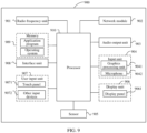
- FIG. 9 is a schematic diagram of a hardware structure of a terminal according to an embodiment of this application.
- the terminal 900 includes but is not limited to components such as a radio frequency unit 901, a network module 902, an audio output unit 903, an input unit 904, a sensor 905, a display unit 906, a user input unit 907, an interface unit 908, a memory 909, and a processor 910.
- the terminal 900 may further include a power supply (such as a battery) for supplying power to the components.
- the power supply may be logically connected to the processor 910 through a power management system. In this way, functions such as charge management, discharge management, and power consumption management are implemented by using the power management system.
- the terminal structure shown in FIG. 9 does not constitute any limitation on the terminal.
- the terminal may include more or fewer components than shown in the figure, or a combination of some components, or components disposed differently. Details are not described herein.
- the input unit 904 may include a graphics processing unit (Graphics Processing Unit, GPU) 9041 and a microphone 9042.
- the graphics processing unit 9041 processes image data of a static picture or a video that is obtained by an image capture apparatus (for example, a camera) in a video capture mode or an image capture mode.
- the display unit 906 may include a display panel 9061, and the display panel 9061 may be configured in a form of a liquid crystal display, an organic light-emitting diode display, or the like.
- the user input unit 907 includes a touch panel 9071 and other input devices 9072.
- the touch panel 9071 is also referred to as a touchscreen.
- the touch panel 9071 may include two parts: a touch detection apparatus and a touch controller.
- the other input devices 9072 may include but are not limited to a physical keyboard, a functional button (such as a volume control button or a power on/off button), a trackball, a mouse, and a joystick. Details are not described herein.
- the radio frequency unit 901 transmits downlink information received from a network-side device to the processor 910 for processing, and in addition, transmits uplink data to the network-side device.
- the radio frequency unit 901 includes but is not limited to an antenna, at least one amplifier, a transceiver, a coupler, a low noise amplifier, and a duplexer.
- the memory 909 may be configured to store software programs or instructions and various data.
- the memory 909 may mainly include a program or instruction storage area and a data storage area.
- the program or instruction storage area may store an operating system, an application program or instructions required by at least one function (for example, an audio playing function and an image playing function), and the like.
- the memory 909 may include a high-speed random access memory, and may further include a non-volatile memory.
- the non-volatile memory may be a read-only memory (Read-Only Memory, ROM), a programmable read-only memory (Programmable ROM, PROM), an erasable programmable read-only memory (Erasable PROM, EPROM), an electrically erasable programmable read-only memory (Electrically EPROM, EEPROM), or a flash memory, for example, at least one magnetic disk storage device, a flash storage device, or another volatile solid-state storage device.
- ROM Read-Only Memory
- PROM programmable read-only memory
- Erasable PROM Erasable PROM
- EPROM electrically erasable programmable read-only memory
- EEPROM electrically erasable programmable read-only memory
- flash memory for example, at least one magnetic disk storage device, a flash storage device, or another volatile solid-state storage device.
- the processor 910 may include one or more processing units.
- the processor 910 may integrate an application processor and a modem processor.
- the application processor mainly processes an operating system, a user interface, an application program or instructions, and the like.
- the modem processor mainly processes wireless communication, for example, a baseband processor. It should be understood that alternatively, the modem processor may not be integrated into the processor 910.
- the radio frequency unit 901 is configured to obtain configuration information for data transmission, where the configuration information carries association configuration information between downlink signal and uplink transmission resource.
- the processor 910 is configured to: select a target downlink signal, and determine, a target uplink transmission resource based on the association configuration information between downlink signal and uplink transmission resource.
- the radio frequency unit 901 is further configured to: determine hybrid automatic repeat request HARQ information corresponding to the target uplink transmission resource and/or estimate a downlink pathloss, and transmit uplink data based on the HARQ information and/or the estimated downlink pathloss.
- the method further includes: receiving, by the terminal, downlink data based on the target downlink signal.
- the association configuration information between downlink signal and uplink transmission resource includes at least one of the following:
- the configuration information further includes at least one of the following:
- the determining hybrid automatic repeat request HARQ information corresponding to the target uplink transmission resource includes: determining the HARQ information corresponding to the target uplink transmission resource based on at least one of the following:
- the estimating a downlink pathloss includes: estimating the downlink pathloss based on the target downlink signal.
- the method further includes at least one of the following:
- the method further includes: after a configuration resource-based data transmission procedure is triggered, performing at least one of the following terminal behaviors:
- the method further includes: setting power ramping step parameter based on a second power ramping step parameter configured by a network-side device, a target access identity, and at least one of a target access type provided by a higher layer, and first indication information transmitted by the network-side device, where the power ramping step parameter includes a first power ramping step parameter and the second power ramping step parameter, and the first indication information is used to indicate that the terminal is to use the second power ramping step parameter.
- the method further includes at least one of the following:
- the HARQ entity performs an uplink skip according to a predefined rule and reports an uplink skip indication to a higher layer.
- the process of transmitting uplink data further includes at least one of the following:
- the receiving downlink data includes:
- a terminal behavior includes at least one of the following:
- a terminal behavior includes at least one of the following:
- FIG. 10 is a schematic diagram of a hardware structure of a network-side device according to an embodiment of this application.
- the network-side device 1000 includes an antenna 1001, a radio frequency apparatus 1002, and a baseband apparatus 1003.
- the antenna 1001 is connected to the radio frequency apparatus 1002.
- the radio frequency apparatus 1002 receives information by using the antenna 1001, and transmits the received information to the baseband apparatus 1003 for processing.
- the baseband apparatus 1003 processes to-be-sent information, and transmits the information to the radio frequency apparatus 1002; and the radio frequency apparatus 1002 processes the received information and then transmits the information by using the antenna 1001.
- the method performed by the network-side device in the foregoing embodiments may be implemented by the baseband apparatus 1003, and the baseband apparatus 1003 includes a processor 1004 and a memory 1005.
- the baseband apparatus 1003 may include, for example, at least one baseband board, where a plurality of chips are disposed on the baseband board. As shown in FIG. 10 , one of the chips is, for example, the processor 1004, and connected to the memory 1005, to invoke the program in the memory 1005 to perform the operations of the network-side device shown in the foregoing method embodiments.
- the baseband apparatus 1003 may further include a network interface 1006 configured to exchange information with the radio frequency apparatus 1002, where the interface is, for example, a common public radio interface (common public radio interface, CPRI for short).
- a common public radio interface common public radio interface, CPRI for short.
- the network-side device in this embodiment of the present invention further includes instructions or a program stored in the memory 1005 and capable of running on the processor 1004.
- the processor 1004 invokes the instructions or program in the memory 1005 to perform the method performed by the modules shown in FIG. 8 , with the same technical effects achieved. To avoid repetition, details are not described herein again.
- An embodiment of this application further provides a readable storage medium.
- the readable storage medium may be volatile or non-volatile, and the readable storage medium stores a program or instructions.
- the program or instructions are executed by a processor, the processes in the foregoing data transmission method embodiments are implemented, with the same technical effects achieved. To avoid repetition, details are not described herein again.
- the processor is a processor in the terminal described in the foregoing embodiment.
- the readable storage medium includes a computer-readable storage medium such as a computer read-only memory (Read-Only Memory, ROM), a random access memory (Random Access Memory, RAM), a magnetic disk, or an optical disc.
- An embodiment of this application further provides a chip, where the chip includes a processor and a communication interface, the communication interface is coupled to the processor, and the processor is configured to run a program or instructions to implement the processes of the foregoing data transmission method embodiments, with the same technical effects achieved. To avoid repetition, details are not described herein again.
- the chip mentioned in this embodiment of this application may also be referred to as a system-level chip, a system chip, a chip system, a system-on-chip, or the like.
- the software product is stored in a storage medium (such as a ROM/RAM, a magnetic disk, or an optical disc), and includes several instructions for instructing a terminal (which may be a mobile phone, a computer, a server, an air conditioner, a network device, or the like) to perform the methods described in the embodiments of this application.
- a storage medium such as a ROM/RAM, a magnetic disk, or an optical disc
- a terminal which may be a mobile phone, a computer, a server, an air conditioner, a network device, or the like
Landscapes
- Engineering & Computer Science (AREA)
- Signal Processing (AREA)
- Computer Networks & Wireless Communication (AREA)
- Quality & Reliability (AREA)
- Physics & Mathematics (AREA)
- Electromagnetism (AREA)
- Mobile Radio Communication Systems (AREA)
Applications Claiming Priority (2)
| Application Number | Priority Date | Filing Date | Title |
|---|---|---|---|
| CN202011141197.2A CN114390694B (zh) | 2020-10-22 | 2020-10-22 | 数据传输方法、装置、终端、网络侧设备及存储介质 |
| PCT/CN2021/124853 WO2022083611A1 (fr) | 2020-10-22 | 2021-10-20 | Procédé et appareil de transmission de données, équipement utilisateur, dispositif côté réseau et support de stockage |
Publications (2)
| Publication Number | Publication Date |
|---|---|
| EP4236529A1 true EP4236529A1 (fr) | 2023-08-30 |
| EP4236529A4 EP4236529A4 (fr) | 2024-04-03 |
Family
ID=81194900
Family Applications (1)
| Application Number | Title | Priority Date | Filing Date |
|---|---|---|---|
| EP21882026.4A Pending EP4236529A4 (fr) | 2020-10-22 | 2021-10-20 | Procédé et appareil de transmission de données, équipement utilisateur, dispositif côté réseau et support de stockage |
Country Status (5)
| Country | Link |
|---|---|
| US (1) | US20230262664A1 (fr) |
| EP (1) | EP4236529A4 (fr) |
| JP (1) | JP7623479B2 (fr) |
| CN (1) | CN114390694B (fr) |
| WO (1) | WO2022083611A1 (fr) |
Families Citing this family (9)
| Publication number | Priority date | Publication date | Assignee | Title |
|---|---|---|---|---|
| EP3723311A1 (fr) * | 2019-04-07 | 2020-10-14 | Fraunhofer Gesellschaft zur Förderung der angewandten Forschung e.V. | Procédés et appareils de gestion des retransmissions dans un système de télécommunications sans fil |
| CN117082627A (zh) * | 2022-05-07 | 2023-11-17 | 维沃移动通信有限公司 | 信息上报方法、装置、通信设备及存储介质 |
| CN117676615A (zh) * | 2022-08-10 | 2024-03-08 | 大唐移动通信设备有限公司 | 确定harq进程标识的方法及装置 |
| KR102878522B1 (ko) * | 2022-12-29 | 2025-10-29 | 현대오토에버 주식회사 | 모빌리티 내의 장치들에 대한 고장 관리 장치 및 그 고장 관리 방법 |
| WO2024164101A1 (fr) * | 2023-02-06 | 2024-08-15 | Huawei Technologies Co., Ltd. | Dispositifs, procédés et système de gestion de transmission de données d'autorisation configurée |
| CN118573335A (zh) * | 2023-02-28 | 2024-08-30 | 维沃移动通信有限公司 | Harq进程id的确定方法、终端及网络侧设备 |
| CN116615951A (zh) * | 2023-03-27 | 2023-08-18 | 北京小米移动软件有限公司 | 一种指示方法、装置、设备及存储介质 |
| CN119138076A (zh) * | 2023-03-31 | 2024-12-13 | 北京小米移动软件有限公司 | 信息传输方法及装置、通信设备、通信系统、存储介质 |
| CN119155001B (zh) * | 2023-06-15 | 2025-11-28 | 大唐移动通信设备有限公司 | 信息传输方法、装置、终端及网络设备 |
Family Cites Families (13)
| Publication number | Priority date | Publication date | Assignee | Title |
|---|---|---|---|---|
| WO2012050838A1 (fr) * | 2010-09-28 | 2012-04-19 | Neocific, Inc. | Procédés et appareil pour une utilisation flexible de bandes de fréquences |
| PT3122110T (pt) * | 2011-07-13 | 2018-11-26 | Sun Patent Trust | Aparelho de estação base e método de transmissão |
| WO2015024215A1 (fr) * | 2013-08-21 | 2015-02-26 | Qualcomm Incorporated | Ressources pucch mappant une rétroaction harq-ack |
| US11546929B2 (en) * | 2017-01-09 | 2023-01-03 | Huawei Technologies Co., Ltd. | Systems and methods for signaling for semi-static configuration in grant-free uplink transmissions |
| CN108633042B (zh) * | 2017-03-24 | 2021-03-30 | 华为技术有限公司 | 一种通信方法、终端及网络设备 |
| EP3606182B1 (fr) * | 2017-04-12 | 2022-02-23 | Guangdong Oppo Mobile Telecommunications Corp., Ltd. | Procédé, dispositif et système de réglage de puissance de liaison montante |
| CN111034329A (zh) * | 2017-08-11 | 2020-04-17 | 高通股份有限公司 | 上行链路早期数据传输 |
| CN110034905B (zh) * | 2018-01-12 | 2022-08-09 | 华为技术有限公司 | 上行信息传输方法及装置 |
| US11606176B2 (en) * | 2018-06-29 | 2023-03-14 | Qualcomm Incorporated | Reference signal and uplink control channel association design |
| US11737084B2 (en) * | 2018-07-30 | 2023-08-22 | Qualcomm Incorporated | Demodulation reference signal port hopping for grant-free physical uplink shared channel communication |
| KR102450969B1 (ko) * | 2018-08-09 | 2022-10-05 | 삼성전자 주식회사 | 무선 통신 시스템에서 경로감쇄 결정 방법 및 장치 |
| US11259331B2 (en) * | 2018-09-27 | 2022-02-22 | Ofinno, Llc | RACH type switching |
| CN111436136B (zh) * | 2019-01-11 | 2022-03-25 | 华为技术有限公司 | 免授权传输的方法及装置 |
-
2020
- 2020-10-22 CN CN202011141197.2A patent/CN114390694B/zh active Active
-
2021
- 2021-10-20 WO PCT/CN2021/124853 patent/WO2022083611A1/fr not_active Ceased
- 2021-10-20 EP EP21882026.4A patent/EP4236529A4/fr active Pending
- 2021-10-20 JP JP2023524538A patent/JP7623479B2/ja active Active
-
2023
- 2023-04-21 US US18/305,225 patent/US20230262664A1/en active Pending
Also Published As
| Publication number | Publication date |
|---|---|
| JP2023546934A (ja) | 2023-11-08 |
| JP7623479B2 (ja) | 2025-01-28 |
| EP4236529A4 (fr) | 2024-04-03 |
| US20230262664A1 (en) | 2023-08-17 |
| CN114390694A (zh) | 2022-04-22 |
| KR20230079275A (ko) | 2023-06-05 |
| CN114390694B (zh) | 2025-07-29 |
| WO2022083611A1 (fr) | 2022-04-28 |
Similar Documents
| Publication | Publication Date | Title |
|---|---|---|
| US20230262664A1 (en) | Data transmission method and apparatus, terminal, network-side device, and storage medium | |
| KR101984848B1 (ko) | Lte 라이센스 지원형 액세스 동작에서의 drx 핸들링 | |
| US9107190B2 (en) | Discontinuous reception for multi-component carrier system | |
| EP2941062A1 (fr) | Procédé de commande d'émission, et procédé et dispositif d'émission | |
| US12538361B2 (en) | Method for setting data transmission type and terminal | |
| US20230208563A1 (en) | Discontinuous reception control method and apparatus, terminal, and readable storage medium | |
| US20230199905A1 (en) | Sidelink discontinuous reception control method and apparatus, device, and readable storage medium | |
| EP4529293A2 (fr) | Procédé et appareil de surveillance de canal de commande de liaison descendante physique (pdcch) et terminal | |
| CN113949492B (zh) | 反馈信息传输方法、装置、终端及网络侧设备 | |
| US12477535B2 (en) | Method for mapping PUSCH signal, terminal, and network-side device | |
| WO2022199544A1 (fr) | Procédé et appareil de transmission en liaison montante et équipement utilisateur | |
| JP2023532537A (ja) | 伝送処理方法、装置及び端末 | |
| US20210235506A1 (en) | Information processing method and apparatus | |
| EP4178293A1 (fr) | Procédé et appareil de suivi et de transmission de canal, terminal et dispositif côté réseau | |
| WO2022001815A1 (fr) | Procédé de surveillance de canal, procédé de transmission, terminal et dispositif côté réseau | |
| CN114696975B (zh) | 速率匹配方法和设备 | |
| EP4247098A1 (fr) | Procédé et appareil de mesure de canal, procédé et appareil de rapport de défaillance de lbt, et dispositif | |
| CN115087121B (zh) | Cot确定方法、上行传输方法和设备 | |
| CN115208529B (zh) | 信号传输方法、终端及网络侧设备 | |
| WO2022228271A1 (fr) | Procédé et appareil de configuration de ressources de synchronisation, équipement utilisateur et support de stockage | |
| KR102942985B1 (ko) | 데이터 전송 방법, 장치, 단말, 네트워크 측 기기 및 저장 매체 | |
| WO2022127898A1 (fr) | Procédé et appareil de transmission de message et dispositif | |
| CN114080060B (zh) | 副链路非连续接收的控制方法及装置 | |
| WO2022194216A1 (fr) | Procédé et dispositif de détermination d'informations | |
| WO2023246562A1 (fr) | Procédé et appareil de traitement de transmission de liaison latérale sur bande sans licence, et dispositif associé |
Legal Events
| Date | Code | Title | Description |
|---|---|---|---|
| STAA | Information on the status of an ep patent application or granted ep patent |
Free format text: STATUS: THE INTERNATIONAL PUBLICATION HAS BEEN MADE |
|
| PUAI | Public reference made under article 153(3) epc to a published international application that has entered the european phase |
Free format text: ORIGINAL CODE: 0009012 |
|
| STAA | Information on the status of an ep patent application or granted ep patent |
Free format text: STATUS: REQUEST FOR EXAMINATION WAS MADE |
|
| 17P | Request for examination filed |
Effective date: 20230419 |
|
| AK | Designated contracting states |
Kind code of ref document: A1 Designated state(s): AL AT BE BG CH CY CZ DE DK EE ES FI FR GB GR HR HU IE IS IT LI LT LU LV MC MK MT NL NO PL PT RO RS SE SI SK SM TR |
|
| DAV | Request for validation of the european patent (deleted) | ||
| DAX | Request for extension of the european patent (deleted) | ||
| REG | Reference to a national code |
Ref country code: DE Ref legal event code: R079 Free format text: PREVIOUS MAIN CLASS: H04W0072040000 Ipc: H04L0001182200 |
|
| A4 | Supplementary search report drawn up and despatched |
Effective date: 20240301 |
|
| RIC1 | Information provided on ipc code assigned before grant |
Ipc: H04W 72/23 20230101ALN20240226BHEP Ipc: H04W 72/1268 20230101ALN20240226BHEP Ipc: H04W 72/02 20090101ALN20240226BHEP Ipc: H04L 1/1867 20230101ALI20240226BHEP Ipc: H04L 1/1829 20230101ALI20240226BHEP Ipc: H04L 1/1825 20230101ALI20240226BHEP Ipc: H04L 5/00 20060101ALI20240226BHEP Ipc: H04L 1/1822 20230101AFI20240226BHEP |