EP4236559A2 - Kommunikationsvorrichtung und verfahren zum betrieb der kommunikationsvorrichtung - Google Patents
Kommunikationsvorrichtung und verfahren zum betrieb der kommunikationsvorrichtung Download PDFInfo
- Publication number
- EP4236559A2 EP4236559A2 EP23170490.9A EP23170490A EP4236559A2 EP 4236559 A2 EP4236559 A2 EP 4236559A2 EP 23170490 A EP23170490 A EP 23170490A EP 4236559 A2 EP4236559 A2 EP 4236559A2
- Authority
- EP
- European Patent Office
- Prior art keywords
- uplink data
- transmission
- grant free
- transmitting
- free resources
- Prior art date
- Legal status (The legal status is an assumption and is not a legal conclusion. Google has not performed a legal analysis and makes no representation as to the accuracy of the status listed.)
- Granted
Links
Images


Classifications
-
- H—ELECTRICITY
- H04—ELECTRIC COMMUNICATION TECHNIQUE
- H04W—WIRELESS COMMUNICATION NETWORKS
- H04W72/00—Local resource management
- H04W72/02—Selection of wireless resources by user or terminal
-
- H—ELECTRICITY
- H04—ELECTRIC COMMUNICATION TECHNIQUE
- H04W—WIRELESS COMMUNICATION NETWORKS
- H04W72/00—Local resource management
- H04W72/12—Wireless traffic scheduling
- H04W72/1263—Mapping of traffic onto schedule, e.g. scheduled allocation or multiplexing of flows
- H04W72/1268—Mapping of traffic onto schedule, e.g. scheduled allocation or multiplexing of flows of uplink data flows
-
- H—ELECTRICITY
- H04—ELECTRIC COMMUNICATION TECHNIQUE
- H04B—TRANSMISSION
- H04B7/00—Radio transmission systems, i.e. using radiation field
- H04B7/02—Diversity systems; Multi-antenna system, i.e. transmission or reception using multiple antennas
- H04B7/04—Diversity systems; Multi-antenna system, i.e. transmission or reception using multiple antennas using two or more spaced independent antennas
- H04B7/06—Diversity systems; Multi-antenna system, i.e. transmission or reception using multiple antennas using two or more spaced independent antennas at the transmitting station
- H04B7/0686—Hybrid systems, i.e. switching and simultaneous transmission
- H04B7/0695—Hybrid systems, i.e. switching and simultaneous transmission using beam selection
- H04B7/06952—Selecting one or more beams from a plurality of beams, e.g. beam training, management or sweeping
-
- H—ELECTRICITY
- H04—ELECTRIC COMMUNICATION TECHNIQUE
- H04L—TRANSMISSION OF DIGITAL INFORMATION, e.g. TELEGRAPHIC COMMUNICATION
- H04L1/00—Arrangements for detecting or preventing errors in the information received
- H04L1/12—Arrangements for detecting or preventing errors in the information received by using return channel
- H04L1/16—Arrangements for detecting or preventing errors in the information received by using return channel in which the return channel carries supervisory signals, e.g. repetition request signals
- H04L1/18—Automatic repetition systems, e.g. Van Duuren systems
- H04L1/1822—Automatic repetition systems, e.g. Van Duuren systems involving configuration of automatic repeat request [ARQ] with parallel processes
-
- H—ELECTRICITY
- H04—ELECTRIC COMMUNICATION TECHNIQUE
- H04L—TRANSMISSION OF DIGITAL INFORMATION, e.g. TELEGRAPHIC COMMUNICATION
- H04L1/00—Arrangements for detecting or preventing errors in the information received
- H04L1/12—Arrangements for detecting or preventing errors in the information received by using return channel
- H04L1/16—Arrangements for detecting or preventing errors in the information received by using return channel in which the return channel carries supervisory signals, e.g. repetition request signals
- H04L1/18—Automatic repetition systems, e.g. Van Duuren systems
- H04L1/1867—Arrangements specially adapted for the transmitter end
- H04L1/189—Transmission or retransmission of more than one copy of a message
-
- H—ELECTRICITY
- H04—ELECTRIC COMMUNICATION TECHNIQUE
- H04W—WIRELESS COMMUNICATION NETWORKS
- H04W52/00—Power management, e.g. Transmission Power Control [TPC] or power classes
- H04W52/04—Transmission power control [TPC]
- H04W52/06—TPC algorithms
- H04W52/14—Separate analysis of uplink or downlink
- H04W52/146—Uplink power control
-
- H—ELECTRICITY
- H04—ELECTRIC COMMUNICATION TECHNIQUE
- H04W—WIRELESS COMMUNICATION NETWORKS
- H04W56/00—Synchronisation arrangements
- H04W56/004—Synchronisation arrangements compensating for timing error of reception due to propagation delay
- H04W56/0045—Synchronisation arrangements compensating for timing error of reception due to propagation delay compensating for timing error by altering transmission time
-
- H—ELECTRICITY
- H04—ELECTRIC COMMUNICATION TECHNIQUE
- H04W—WIRELESS COMMUNICATION NETWORKS
- H04W72/00—Local resource management
- H04W72/04—Wireless resource allocation
- H04W72/044—Wireless resource allocation based on the type of the allocated resource
- H04W72/0446—Resources in time domain, e.g. slots or frames
-
- H—ELECTRICITY
- H04—ELECTRIC COMMUNICATION TECHNIQUE
- H04W—WIRELESS COMMUNICATION NETWORKS
- H04W72/00—Local resource management
- H04W72/04—Wireless resource allocation
- H04W72/115—Grant-free or autonomous transmission
-
- H—ELECTRICITY
- H04—ELECTRIC COMMUNICATION TECHNIQUE
- H04L—TRANSMISSION OF DIGITAL INFORMATION, e.g. TELEGRAPHIC COMMUNICATION
- H04L1/00—Arrangements for detecting or preventing errors in the information received
- H04L1/08—Arrangements for detecting or preventing errors in the information received by repeating transmission, e.g. Verdan system
-
- H—ELECTRICITY
- H04—ELECTRIC COMMUNICATION TECHNIQUE
- H04L—TRANSMISSION OF DIGITAL INFORMATION, e.g. TELEGRAPHIC COMMUNICATION
- H04L1/00—Arrangements for detecting or preventing errors in the information received
- H04L1/12—Arrangements for detecting or preventing errors in the information received by using return channel
- H04L1/16—Arrangements for detecting or preventing errors in the information received by using return channel in which the return channel carries supervisory signals, e.g. repetition request signals
- H04L1/18—Automatic repetition systems, e.g. Van Duuren systems
- H04L1/1812—Hybrid protocols; Hybrid automatic repeat request [HARQ]
-
- H—ELECTRICITY
- H04—ELECTRIC COMMUNICATION TECHNIQUE
- H04W—WIRELESS COMMUNICATION NETWORKS
- H04W72/00—Local resource management
- H04W72/50—Allocation or scheduling criteria for wireless resources
- H04W72/56—Allocation or scheduling criteria for wireless resources based on priority criteria
- H04W72/566—Allocation or scheduling criteria for wireless resources based on priority criteria of the information or information source or recipient
- H04W72/569—Allocation or scheduling criteria for wireless resources based on priority criteria of the information or information source or recipient of the traffic information
Definitions
- the present disclosure relates to communications devices, methods of operating communications devices, infrastructure equipment and methods for communicating uplink data using grant free resources in wireless communications networks.
- Third and fourth generation mobile telecommunication systems such as those based on the 3GPP defined UMTS and Long Term Evolution (LTE) architecture, are able to support more sophisticated services than simple voice and messaging services offered by previous generations of mobile telecommunication systems.
- LTE Long Term Evolution
- a user is able to enjoy high data rate applications such as mobile video streaming and mobile video conferencing that would previously only have been available via a fixed line data connection.
- the demand to deploy such networks is therefore strong and the coverage area of these networks, i.e. geographic locations where access to the networks is possible, may be expected to increase ever more rapidly.
- Future wireless communications networks will be expected to routinely and efficiently support communications with a wider range of devices associated with a wider range of data traffic profiles and types than current systems are optimised to support. For example it is expected future wireless communications networks will be expected to efficiently support communications with devices including reduced complexity devices, machine type communication (MTC) devices, high resolution video displays, virtual reality headsets and so on. Some of these different types of devices may be deployed in very large numbers, for example low complexity devices for supporting the "The Internet of Things", and may typically be associated with the transmissions of relatively small amounts of data with relatively high latency tolerance.
- MTC machine type communication
- Ultra Reliable Low Latency Communications (URLLC) services which, as its name suggests, requires that a data unit or packet be communicated with a high reliability and with a low communications delay.
- URLLC type services therefore represent a challenging example for both LTE type communications systems and 5G/NR communications systems.
- grant free resources have been provided for transmitting uplink data as well as downlink data, which can reduce a latency of transmitting the uplink/downlink data.
- some further adaptation may be required for transmission and reception of data to take advantage of the lower latency can be achieved using grant fee resources.
- the present disclosure can help address or mitigate at least some of the issues discussed above.
- Embodiments of the present technique can provide a method of operating a communications device to transmit data to a wireless communications network, the method comprising processing uplink data for transmission on grant free resources of a physical uplink shared channel of a wireless access interface provided by the wireless communications network to form one or more transport blocks of the uplink data for transmission.
- the grant free resources provide communications resources of the physical shared uplink channel in each of a plurality of time divided units of the wireless access interface for transmitting the uplink data.
- the method comprises selecting one of a plurality of configurations for transmitting the uplink data in the grant free resources, and transmitting the uplink data in the grant free resources according to the selected configuration.
- Each of the plurality of configurations includes grant free resources, a transmission period in which each of the encoded data units is to be transmitted in the grant free resources, and a temporal starting position of the transmission period in one of the time divided units of the wireless access interface for transmitting the uplink data in the grant free resources, the temporal starting position and the transmission period being independent for each of the plurality of configurations.
- a configuration can be selected to match a time of generation of the one or more transport blocks according to a required time when the uplink data should be transmitted. As a result the uplink data can be transmitted with a lower latency in the grant free resources.
- each of the plurality of configurations for transmitting the uplink data may include different communications parameters for transmitting the uplink data.
- each of the plurality of configurations for transmitting the uplink data in the grant free communications resources includes a relative priority for transmitting the uplink data with respect to transmitting the uplink data according to a different configuration. As such when there is a potential conflict for accessing the same uplink grant free resources, the transmitting of the uplink data with one of the configurations with a lower priority is adapted so that it does not conflict with the transmission of the uplink data with a configuration with a higher priority.
- Embodiments of the present technique which further relate to infrastructure equipment, communications devices as well as methods of operating communications devices, and infrastructure equipment, methods and circuitry for communications devices and infrastructure equipment, can provide an improvement in the transmission of uplink data using grant free communications resources.
- Figure 1 provides a schematic diagram illustrating some basic functionality of a mobile telecommunications network / system 100 operating generally in accordance with LTE principles, but which may also support other radio access technologies, and which may be adapted to implement embodiments of the disclosure as described herein.
- Various elements of Figure 1 and certain aspects of their respective modes of operation are well-known and defined in the relevant standards administered by the 3GPP (RTM) body, and also described in many books on the subject, for example, Holma H. and Toskala A [2].
- the network 100 includes a plurality of base stations 101 connected to a core network part 102.
- Each base station provides a coverage area 103 (e.g. a cell) within which data can be communicated to and from communications devices 104.
- Data is transmitted from the base stations 101 to the communications devices 104 within their respective coverage areas 103 via a radio downlink.
- Data is transmitted from the communications devices 104 to the base stations 101 via a radio uplink.
- the core network part 102 routes data to and from the communications devices 104 via the respective base stations 101 and provides functions such as authentication, mobility management, charging and so on.
- Communications devices may also be referred to as mobile stations, user equipment (UE), user terminals, mobile radios, communications devices, and so forth.
- Base stations which are an example of network infrastructure equipment / network access nodes, may also be referred to as transceiver stations / nodeBs / e-nodeBs, g-nodeBs (gNB) and so forth.
- transceiver stations / nodeBs / e-nodeBs, g-nodeBs (gNB) and so forth.
- gNB g-nodeBs
- different terminology is often associated with different generations of wireless telecommunications systems for elements providing broadly comparable functionality.
- example embodiments of the disclosure may be equally implemented in different generations of wireless telecommunications systems such as 5G or new radio as explained below, and for simplicity certain terminology may be used regardless of the underlying network architecture. That is to say, the use of a specific term in relation to certain example implementations is not intended to indicate these implementations are limited to a certain generation of network that may be most associated with that particular terminology.
- FIG. 2 is a schematic diagram illustrating a network architecture for a new RAT wireless communications network / system 200 based on previously proposed approaches which may also be adapted to provide functionality in accordance with embodiments of the disclosure described herein.
- the new RAT network 200 represented in Figure 2 comprises a first communication cell 201 and a second communication cell 202.
- Each communication cell 201, 202 comprises a controlling node (centralised unit) 221, 222 in communication with a core network component 210 over a respective wired or wireless link 251, 252.
- the respective controlling nodes 221, 222 are also each in communication with a plurality of distributed units (radio access nodes / remote transmission and reception points (TRPs)) 211, 212 in their respective cells.
- TRPs remote transmission and reception points
- the distributed units 211, 212 are responsible for providing the radio access interface for communications devices connected to the network.
- Each distributed unit 211, 212 has a coverage area (radio access footprint) 241, 242 where the sum of the coverage areas of the distributed units under the control of a controlling node together define the coverage of the respective communication cells 201, 202.
- Each distributed unit 211, 212 includes transceiver circuitry for transmission and reception of wireless signals and processor circuitry configured to control the respective distributed units 211, 212.
- the core network component 210 of the new RAT communications network represented in Figure 2 may be broadly considered to correspond with the core network 102 represented in Figure 1 , and the respective controlling nodes 221, 222 and their associated distributed units / TRPs 211, 212 may be broadly considered to provide functionality corresponding to the base stations 101 of Figure 1 .
- the term network infrastructure equipment / access node may be used to encompass these elements and more conventional base station type elements of wireless communications systems.
- the responsibility for scheduling transmissions which are scheduled on the radio interface between the respective distributed units and the communications devices may lie with the controlling node / centralised unit and / or the distributed units / TRPs.
- a communications device or UE 260 is represented in Figure 2 within the coverage area of the first communication cell 201.
- This communications device 400 may thus exchange signalling with the first controlling node 221 in the first communication cell via one of the distributed units 211 associated with the first communication cell 201.
- communications for a given communications device are routed through only one of the distributed units, but it will be appreciated in some other implementations communications associated with a given communications device may be routed through more than one distributed unit, for example in a soft handover scenario and other scenarios.
- two communication cells 201, 202 and one communications device 400 are shown for simplicity, but it will of course be appreciated that in practice the system may comprise a larger number of communication cells (each supported by a respective controlling node and plurality of distributed units) serving a larger number of communications devices.
- Figure 2 represents merely one example of a proposed architecture for a new RAT communications system in which approaches in accordance with the principles described herein may be adopted, and the functionality disclosed herein may also be applied in respect of wireless communications systems having different architectures.
- example embodiments of the disclosure as discussed herein may be implemented in wireless telecommunication systems / networks according to various different architectures, such as the example architectures shown in Figures 1 and 2 . It will thus be appreciated the specific wireless communications architecture in any given implementation is not of primary significance to the principles described herein. In this regard, example embodiments of the disclosure may be described generally in the context of communications between network infrastructure equipment / access nodes and a communications device, wherein the specific nature of the network infrastructure equipment / access node and the communications device will depend on the network infrastructure for the implementation at hand.
- the network infrastructure equipment / access node may comprise a base station, such as an LTE-type base station 101 as shown in Figure 1 which is adapted to provide functionality in accordance with the principles described herein, and in other examples the network infrastructure equipment / access node may comprise a control unit / controlling node 221, 222 and / or a TRP 211, 212 of the kind shown in Figure 2 which is adapted to provide functionality in accordance with the principles described herein.
- a base station such as an LTE-type base station 101 as shown in Figure 1 which is adapted to provide functionality in accordance with the principles described herein
- the network infrastructure equipment / access node may comprise a control unit / controlling node 221, 222 and / or a TRP 211, 212 of the kind shown in Figure 2 which is adapted to provide functionality in accordance with the principles described herein.
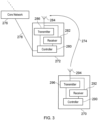
- FIG. 3 A more detailed illustration of a UE 270 and an example network infrastructure equipment 272, which may be thought of as a gNB 101 or a combination of a controlling node 221 and TRP 211, is presented in Figure 3 .
- the UE 270 is shown to transmit uplink data to the infrastructure equipment 272 via grant free resources of a wireless access interface as illustrated generally by an arrow 274.
- the infrastructure equipment 272 is connected to a core network 276 via an interface 278 to a controller 280 of the infrastructure equipment 272.
- the infrastructure equipment 272 includes a receiver 282 connected to an antenna 284 and a transmitter 286 connected to the antenna 284.
- the UE 270 includes a controller 290 connected to a receiver 292 which receives signals from an antenna 294 and a transmitter 296 also connected to the antenna 294.
- the controller 280 is configured to control the infrastructure equipment 272 and may comprise processor circuitry which may in turn comprise various sub-units / sub-circuits for providing functionality as explained further herein. These sub-units may be implemented as discrete hardware elements or as appropriately configured functions of the processor circuitry. Thus the controller 280 may comprise circuitry which is suitably configured / programmed to provide the desired functionality using conventional programming / configuration techniques for equipment in wireless telecommunications systems.
- the transmitter 286 and the receiver 282 may comprise signal processing and radio frequency filters, amplifiers and circuitry in accordance with conventional arrangements.
- the transmitter 286, the receiver 282 and the controller 280 are schematically shown in Figure 3 as separate elements for ease of representation.
- the functionality of these elements can be provided in various different ways, for example using one or more suitably programmed programmable computer(s), or one or more suitably configured application-specific integrated circuit(s) / circuitry / chip(s) / chipset(s).
- the infrastructure equipment 101 will in general comprise various other elements associated with its operating functionality.
- the controller 290 of the UE 270 is configured to control the transmitter 296 and the receiver 292 and may comprise processor circuitry which may in turn comprise various sub-units / sub-circuits for providing functionality as explained further herein. These sub-units may be implemented as discrete hardware elements or as appropriately configured functions of the processor circuitry.
- the controller 290 may comprise circuitry which is suitably configured / programmed to provide the desired functionality using conventional programming / configuration techniques for equipment in wireless telecommunications systems.
- the transmitter 296 and the receiver 292 may comprise signal processing and radio frequency filters, amplifiers and circuitry in accordance with conventional arrangements.
- the transmitter 296, receiver 292 and controller 290 are schematically shown in Figure 3 as separate elements for ease of representation.
- the functionality of these elements can be provided in various different ways, for example using one or more suitably programmed programmable computer(s), or one or more suitably configured application-specific integrated circuit(s) / circuitry / chip(s) / chipset(s).
- the communications device 104 will in general comprise various other elements associated with its operating functionality, for example a power source, user interface, and so forth, but these are not shown in Figure 3 in the interests of simplicity.
- Example embodiments described below can find application with advanced wireless communications systems such as those referred to as 5G or New Radio (NR) Access Technology.
- the use cases that are considered for NR include:
- Embodiments described below provide a more efficient arrangement for communicating uplink data via grant free resources of an uplink of the wireless access interface. This is because a timing structure of the uplink grant free resources may not match a timing with which the uplink data is encoded for transmission.
- a better appreciation provided by the example embodiments can be gained from reviewing a proposed wireless access interface according to 3GPP LTE/4G and NR/5G.
- a wireless access interface in accordance with a 3GPP Standard for LTE is described in detail in Annex 1 in which Figures 16 and 17 provide detailed representation of a wireless access interface for the downlink and the uplink respectively. More details of the LTE wireless access interface are therefore described in Annex 1.
- the wireless access interface provides physical communications resources including shared channels for both uplink and the downlink which may be accessed by communicating appropriate control signalling as those acquainted with LTE will appreciate.
- a wireless access interface for the 5G Standard as represented in Figure 2 may be similarly formed in accordance with the arrangement shown in Annex 1 and may use OFDM on the downlink and OFDM or SC-FDMA on the uplink.
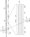
- Figure 4 provides a simplified representation of an uplink frame/sub-frame structure based on the NR wireless access interface structure.
- a simplified version of the uplink frame/sub-frame structure is provided in order to assist in the explanation of the example embodiments.
- the uplink of the wireless access interface is shown to comprise frames 300 with respect to which the UE 270 transmits uplink data to the infrastructure equipment 272. Consistent with the explanation provided in Annex 1, the uplink comprises in each frame 300 ten sub-frames 301.
- a frame 300 is defined by 10 ms
- a sub-frame 301 is defined by 1 ms
- a slot 302 is defined by fourteen OFDM symbols, irrespective of subcarrier spacing.
- FIG 4 30 kHz subcarrier spacing is assumed.
- An expanded view of the components of a sub-frame 310 are shown to be formed from two consecutive slots n-1, n 302, include physical resources of a shared channel as well as control channels as explained in Annex 1 with reference to Figure 15 .
- PUSCH uplink shared channel
- a NR or 5G wireless access interface as controlled for example a the controller 272 of the infrastructure equipment 272 is the provision of grant free access to communications resources for transmitting uplink data.
- the communications device may transmit, in response, a Scheduling Request (SR) to the network.
- the SR may comprise a buffer status report (BSR), indicating an amount of data in the MAC layer buffer(s).
- BSR buffer status report
- the network for example, the infrastructure equipment
- the DCI may be transmitted on a physical downlink control channel (PDCCH).
- PDCH physical downlink control channel
- the uplink grant may comprise an indication of uplink communications resources which are allocated (or, in other words, scheduled) for the communications device to transmit its uplink data.
- the uplink communications resources may be on a physical uplink shared channel (PUSCH). This type of resource allocation is known as grant based resource. Grant based resources are suitable for services where the data arrives in variable amounts, and/or is aperiodic, even if such the data traffic arrival follows a somewhat predictable traffic pattern.
- grant free resources are a set of periodically repeating uplink communications resources which are semi-statically configured by the network for the use of the communications device for uplink transmission. Grant free resources allocation is particularly suitable for services that generate periodic data traffic, where the amount generated is broadly constant over time.
- the grant free resources can improve the efficiency with which communications resources are used, since there is no need for either a SR or uplink grant to be transmitted in respect of each uplink data transmission.
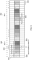
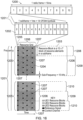
- An illustration of grant free resources for communicating uplink data is shown in Figure 5 based on the frame/sub-frame/slot structure illustrated in Figure 4 .
- the two slots n-1, n 302.1, 302.2, which each comprise fourteen OFDM symbols 303 are shown to include a section of grant free resources in each slot 360, 362 from OFDM symbol numbered 4 to 11.
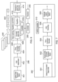
- uplink data for transmission is formed into transport blocks by for example a medium access control layer and passed to a physical layer for transmission by an uplink data transport block 401.
- the uplink transport blocks are then fed to a CRC Attachment block 402, which calculates a cyclic redundancy check (CRC) on each transport data block before passing the combined CRC parity check bits and data bits representing to an error correction encoder 404.
- the error correction encoder encodes the CRC and the data bits of the transport blocks to form error correction encoded transport blocks 440 for transmission on the grant free resources 360, 363.
- the error correction encoded transport blocks are then received by a rate matching, repetition and hybrid automatic repeat request (HARQ) block 406 which includes an encoded data unit former 408 and a repetition block 410.
- HARQ rate matching, repetition and hybrid automatic repeat request
- the rate matching, repetition and HARQ block 406 is controlled by a controller 412 to generate encoded data units 442 for transmission by a transmission block 414 on the uplink grant free resources.
- FIG. 7 A schematic block diagram of the receiver 282 of the infrastructure equipment 272 for detecting radio signals transmitted from the UE 270 in the grant free resources and for decoding the encoded transport block represent by the radio signals is shown in Figure 7 .
- a detection block 501 detects the encoded units of data transmitted uplink grant free resources 360, 363 from the UE 270.
- the encoded data units making up each encoded transport block may be transmitted using a HARQ scheme and a repetition scheme in which the same encoded data unit is transmitted repeatedly in the uplink grant free resources. Therefore after detecting the encoded data units, a reassemble encoded transport block element 502 reassembles the encoded transport blocks from the encoded data units and feeds the encoded transport blocks to an error correction decoder 504.
- the reassemble block 502 may combine the repeated receptions of the encoded data units by soft-combining to reassemble the transport blocks, where soft-combination can comprise addition of log-likelihood ratios (LLRs) for received soft bits of the repetitions.
- the error correction decoder 504 decodes the encoded transport block and generates an estimate of the data in accordance with the error correction encoding scheme being used at the transmitter.
- a CRC decoder 506 performs CRC in accordance with a conventional arrangement to detect whether the uplink data in the transport block has been correctly received which outputs to the uplink data to a processing block 508.
- the encoded transport blocks 440 may be transmitted via the grant free uplink resources using a HARQ scheme combined with repeated transmission.
- the rate matching, repetition and HARQ block 406 may divide the encoded transport blocks 440 into encoded data units 442 for transmission via the grant free resources of the uplink.
- the encoded data units may be rate matched by puncturing the bits, for example where each encoded data unit 442 is to be transmitted one or more of the OFDM symbols in the slot 360, 362.
- each encoded data unit may be transmitted according to a HARQ process in which the HARQ process gives each encoded data unit 442 a HARQ identifier.
- the HARQ identifier may be matched to the slot or sub-frame number rather than a time of generating each data unit in the transmitter 296.
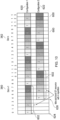
- the rate matching, repetition and HARQ block 406 may transmit each of the encoded data unit a repeated number of times in order to improve integrity of the communicated uplink data by improving a likelihood that the uplink data is received correctly. For example it has been proposed for 3GPP release-16 to perform repeated transmission based on a mini-slot structure.
- Figure 8 provides an example in which an encoded data unit 442 is transmitted four times in each mini-slot, which is eight OFDM symbols of the slot 360, 362, so that each of the slots 360, 363 is divided in half to form the mini-slots 550, 552, 554, 556.
- previously proposed arrangements for uplink grant free transmission for example in the PUSCH can include transmitting K repetitions of encoded data units, where each encoded data unit 442 is transmitted in a transmission occasion, which may be for example a slot 360, 362. These K repetitions are transmitted over multiple transmission occasions (TO) where several TO form a transmission period for transmitting each encoded data unit.
- the TO implicitly indicates to the receiver 282 in the infrastructure equipment 272 a version of the encoded data unit, which can be referred to as a Redundancy Version whilst the transmission period implicitly indicates to the receiver 282 the HARQ process identifier.
- the transmitter 296 of the UE 270 may not be able to transmit K repetitions since it may reach the end of the transmission period and hence a change in HARQ process identifier before the K repetitions have been transmitted.
- a starting opportunity of the repeated transmission of an encoded data unit depends on the number of repetition K.
- a frequency of the starting opportunity affects the latency with which the encoded data unit 442 and therefore the transport block 440 is transmitted.
- the frequency of the starting opportunity is increased, thereby providing s lower latency but the reduced number of repetition will reduce the communication reliability.
- a communication reliability is increased but the frequency of the starting opportunity for transmitting the encoded data unit is reduced thereby increasing the latency of transmission.
- a URLLC PUSCH that starts in the middle of a transmission period may not have sufficient transmission occasions to complete the targeted K repetitions of a transmission period.
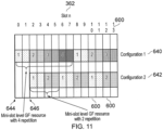
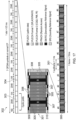
- One proposal is to have multiple grant free configurations where in each of this GF resource the transmission period starts at a different time [4], i.e. staggered in time.
- two configurations 620, 622 of grant free resources is shown where Configuration 1 620 starts its transmission period at the beginning of Slot n- 1 624 whilst Configuration 2 622 starts at the OFDM symbol#4 626 which is therefore staggered in time.
- Configuration 1 620 starts its transmission period at the beginning of Slot n- 1 624 whilst Configuration 2 622 starts at the OFDM symbol#4 626 which is therefore staggered in time.
- Embodiments of the present technique can provide an improvement in accessing grant free resources.
- embodiments of the present technique can provide:
- Embodiments of the present technique can provide an arrangement in which the UE 296 is configured to transmit data to a wireless communications network by processing uplink data for transmission on the grant free resources of the uplink to form one or more transport block of the uplink data, the grant free resources providing communications resources in each of a plurality of time divided units of the wireless access interface for transmitting the uplink data, such as the time slots 360, 362 or the mini-slots 550, 552, 554, 556.
- the method includes selecting one of a plurality of configurations for transmitting the uplink data in the grant free resources, and transmitting the one or more transport blocks in the grant free resources according to the selected configuration.
- Each of the plurality of configuration includes a transmission period for transmitting the one or more transport blocks in the time divided units of the wireless access interface, the temporal starting position and the transmission period, the transmission period and the starting position of the transmission period are independently set for each of the plurality of configurations and may therefore be different for each of the plurality of configurations.
- the processing of the uplink data for transmission includes forming the uplink data into the uplink transport blocks for transmission, encoding each of the uplink transport blocks to encoded transport blocks, forming from each of the encoded transport blocks a plurality of encoded data units, each of the encoded data units being formed for repeated transmission in each of a plurality of transmission occasions forming each of the transmission periods in communications resources of the uplink grant free resources.
- Each of the plurality of configurations therefore includes a number of repetitions for transmitting the encoded data units which is different for each configuration, providing for each configuration a different transmission period.
- Example embodiments can therefore provide a plurality of configurations of the transmitter on the UE and receiver in the infrastructure equipment for using grant free resources for transmitting uplink data from different sources having different quality of service requirements and therefore different priorities and/or different requirements for URLLC.
- the multiple configuration for grant free transmission can have different parameters. For example, the following parameters are independently configured for each configuration for grant free transmission:
- data to be transmitted for different services from different sources may each have a different configuration and the data from each of the services/sources may have a different relative transmission priority for accessing the grant free resources from the UE.
- the UE may therefore transmit data from different sources but prioritise the transmission of the data which may be transmitted according to the different configurations.
- a UE is configured with two configurations for using the grant free resources, each configuration having a different starting position (OFDM symbol) for the repeated transmission of the encoded data unit, one can be prioritised with respect to the other according to a relative priority of each service type/source.
- the uplink data with a higher priority is required to be transmitted during transmission of different uplink data with a lower priority
- the uplink data with the higher priority can be prioritized. That is to say multiple grant free resources configurations are associated with a different priority and accordingly transmission on the grant free resources is given a priority such that the higher priority grant free resources can pre-empt a lower priority grant free resources within the same UE.
- uplink data is transmitted from different sources using different configurations on the grant free resources.
- the multiplexing may be achieved in one example by mapping the data from different sources with different configurations by mapping the data on to different frequency resources.
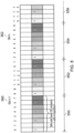
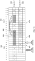
- the data can be overlapped on the same frequency resources as shown in the example embodiment illustrated in Figure 15 .
- uplink data is transmitted in the grant free resources according to the first configuration 1 660 (in which repetition numbers 1 to 4 are shown as underlined) or the uplink data transmitted according to the second configuration 2 662 (in which repetition numbers 1 to 4 are shown in italic font), e.g. depending on a timing of uplink data generation.
- a UE can explicitly or implicitly indicate to gNB which the configured grant free resources is used.
- infrastructure equipment and/or communications devices as herein defined may be further defined in accordance with the various arrangements and embodiments discussed in the preceding paragraphs. It would be further appreciated by those skilled in the art that such infrastructure equipment and communications devices as herein defined and described may form part of communications systems other than those defined by the present invention.
- Described embodiments may be implemented in any suitable form including hardware, software, firmware or any combination of these. Described embodiments may optionally be implemented at least partly as computer software running on one or more data processors and/or digital signal processors.
- the elements and components of any embodiment may be physically, functionally and logically implemented in any suitable way. Indeed the functionality may be implemented in a single unit, in a plurality of units or as part of other functional units. As such, the disclosed embodiments may be implemented in a single unit or may be physically and functionally distributed between different units, circuitry and/or processors.
- Embodiments of the present technique are not limited to a particular wireless communications standard, but find general application with a mobile communications system in which a transmitter and a receiver are configured to communicate data in units, transport blocks or packets for which some indication of feedback is provided as part of an ARQ type protocol.
- a wireless access interface configured in accordance with an LTE standard uses an orthogonal frequency division modulation (OFDM) based wireless access interface for the radio downlink (so-called OFDMA) and a single carrier frequency division multiple access scheme (SC-FDMA) on the radio uplink.
- OFDM orthogonal frequency division modulation
- SC-FDMA single carrier frequency division multiple access scheme
- Figure 16 provides a simplified schematic diagram of the structure of a downlink of a wireless access interface that may be provided by or in association with the eNB of Figure 1 when the communications system is operating in accordance with the LTE standard.
- the wireless access interface of the downlink from an eNB to a UE is based upon an orthogonal frequency division multiplexing (OFDM) access radio interface.
- OFDM orthogonal frequency division multiplexing
- the resources of the available bandwidth are divided in frequency into a plurality of orthogonal subcarriers and data is transmitted in parallel on a plurality of orthogonal subcarriers, where bandwidths between 1.4MHZ and 20MHz bandwidth may be divided into orthogonal subcarriers.
- subcarriers are used to transmit data (some are used to carry reference information used for channel estimation at the receiver for example) whilst some at the edge of the band are not used at all.
- the number of subcarriers varies between 72 subcarriers (1.4MHz) and 1200 subcarriers (20MHz), but it will be appreciated that for other wireless access interfaces, such as NR or 5G, the number of sub-carriers and the bandwidth may be different.
- the subcarriers are grouped on a basis of 2 n , for example 128 to 2048, so that both a transmitter and a receiver can use an inverse and a forward Fast Fourier Transform to convert the sub-carriers from the frequency domain to the time domain and from the time domain to the frequency domain respectively.
- Each subcarrier bandwidth may take any value but in LTE it is fixed at 15kHz.
- the resources of the wireless access interface are also temporally divided into frames where a frame 200 lasts 10ms and is subdivided into 10 sub-frames 1201 each with a duration of 1ms.
- Each sub-frame 201 is formed from 14 OFDM symbols and is divided into two slots 1220, 1222 each of which comprise six or seven OFDM symbols depending on whether a normal or extended cyclic prefix is being utilised within OFDM symbols for the reduction of inter symbol interference.
- the resources within a slot may be divided into resources blocks 1203 each comprising 12 subcarriers for the duration of one slot and the resource blocks are further divided into resource elements 1204 which span one subcarrier for one OFDM symbol, where each rectangle 1204 represents a resource element.
- the resource elements distributed in time within a sub-frame and frequency across the host system bandwidth represent the communications resources of the host system.
- each sub-frame 1201 which comprises a control region 1205 for the transmission of control data, a data region 1206 for the transmission of user data and reference signals 207 which are interspersed in the control and data regions in accordance with a predetermined pattern.
- the control region 1205 may contain a number of physical channels for the transmission of control data, such as a physical downlink control channel (PDCCH), a physical control format indicator channel (PCFICH) and a physical HARQ indicator channel (PHICH).
- PDCCH physical downlink control channel
- PCFICH physical control format indicator channel
- PHICH physical HARQ indicator channel
- the data region may contain a number of physical channels for the transmission of data or control, such as a physical downlink shared channel (PDSCH), enhanced physical downlink control channel (ePDCCH) and a physical broadcast channel (PBCH).
- PDSCH physical downlink shared channel
- ePDCCH enhanced physical downlink control channel
- PBCH physical broadcast channel
- Resources within the PDSCH may be allocated by an eNodeB to UEs being served by the eNodeB. For example, a number of resource blocks of the PDSCH may be allocated to a UE in order that it may receive data that it had previously requested or data which is being pushed to it by the eNodeB, such as radio resource control (RRC) signalling.
- RRC radio resource control
- UE1 has been allocated resources 1208 of the data region 1206, UE2 resources 1209 and UE3 resources 1210.
- UEs in an LTE system may be allocated a fraction of the available resources for the PDSCH and therefore UEs are required to be informed of the location of their allocated resources within the PDCSH so that only relevant data within the PDSCH is detected and estimated.
- DCI downlink control information
- FIG 17 provides a simplified schematic diagram of the structure of an uplink of an LTE wireless access interface that may be provided by or in association with the eNodeB of Figure 1 .
- the uplink wireless access interface is based upon a single carrier frequency division multiplexing FDM (SC-FDM) interface and downlink and uplink wireless access interfaces may be provided by frequency division duplexing (FDD) or time division duplexing (TDD), where in TDD implementations sub-frames switch between uplink and downlink sub-frames in accordance with predefined patterns.
- FDD frequency division duplexing
- TDD time division duplexing
- a common uplink frame structure is utilised.
- the simplified structure of Figure 3 illustrates such an uplink frame in an FDD implementation.
- a frame 300 is divided into 10 sub-frames 301 of 1ms duration where each sub-frame 301 comprises two slots 302 of 0.5ms duration.
- Each slot 302 is then formed from seven OFDM symbols 303 where a cyclic prefix 304 is inserted between each symbol in a manner equivalent to that in downlink sub-frames.
- each LTE uplink sub-frame may include a plurality of different channels, for example a physical uplink communications channel (PUSCH) 305, a physical uplink control channel (PUCCH) 306, and a physical random access channel (PRACH).
- the physical Uplink Control Channel (PUCCH) may carry control information such as ACK/NACK to the eNodeB for downlink transmissions, scheduling request indicators (SRI) for UEs wishing to be scheduled uplink resources, and feedback of downlink channel state information (CSI) for example.
- the PUSCH may carry UE uplink data or some uplink control data.
- Resources of the PUSCH are granted via PDCCH, such a grant being typically triggered by communicating to the network the amount of data ready to be transmitted in a buffer at the UE.
- the PRACH may be scheduled in any of the resources of an uplink frame in accordance with a one of a plurality of PRACH patterns that may be signalled to UE in downlink signalling such as system information blocks.
- uplink sub-frames may also include reference signals.
- demodulation reference signals (DMRS) 307 and sounding reference signals (SRS) 308 may be present in an uplink sub-frame where the DMRS occupy the fourth symbol of a slot in which PUSCH is transmitted and are used for decoding of PUCCH and PUSCH data, and where SRS are used for uplink channel estimation at the eNodeB.
- the ePDCCH channel carries similar control information (DCI) as the PDCCH, but the physical aspects of PDCCH are different to those of ePDCCH, as discussed elsewhere herein. Further information on the structure and functioning of the physical channels of LTE systems can be found in [1].
- resources of the PUSCH are required to be scheduled or granted by the serving eNodeB and thus if data is to be transmitted by a UE, resources of the PUSCH are required to be granted to the UE by the eNodeB.
- PUSCH resource allocation is achieved by the transmission of a scheduling request or a buffer status report to its serving eNodeB.
- the scheduling request may be made, when there is insufficient uplink resource for the UE to send a buffer status report, via the transmission of Uplink Control Information (UCI) on the PUCCH when there is no existing PUSCH allocation for the UE, or by transmission directly on the PUSCH when there is an existing PUSCH allocation for the UE.
- UCI Uplink Control Information
- the eNodeB In response to a scheduling request, the eNodeB is configured to allocate a portion of the PUSCH resource to the requesting UE sufficient for transferring a buffer status report and then inform the UE of the buffer status report resource allocation via a DCI in the PDCCH.
- the buffer status report is sent to the eNodeB and gives the eNodeB information regarding the amount of data in an uplink buffer or buffers at the UE.
- the eNodeB can allocate a portion of the PUSCH resources to the sending UE in order to transmit some of its buffered uplink data and then inform the UE of the resource allocation via a DCI in the PDCCH.
- the UE presuming a UE has a connection with the eNodeB, the UE will first transmit a PUSCH resource request in the PUCCH in the form of a UCI. The UE will then monitor the PDCCH for an appropriate DCI, extract the details of the PUSCH resource allocation, and transmit uplink data, at first comprising a buffer status report, and/or later comprising a portion of the buffered data, in the allocated resources.
- uplink sub-frames have a different control structure to downlink sub-frames, in particular the upper 309 and lower 310 subcarriers/frequencies/resource blocks of an uplink sub-frame are reserved for control signalling rather than the initial symbols of a downlink sub-frame.
- the resource allocation procedure for the downlink and uplink are relatively similar, the actual structure of the resources that may be allocated may vary due to the different characteristics of the OFDM and SC-FDM interfaces that are used in the downlink and uplink respectively.
- each subcarrier is individually modulated and therefore it is not necessary that frequency/subcarrier allocation are contiguous however, in SC-FDM subcarriers are modulated in combination and therefore if efficient use of the available resources are to be made, contiguous frequency allocations for each UE may be preferable.
Landscapes
- Engineering & Computer Science (AREA)
- Computer Networks & Wireless Communication (AREA)
- Signal Processing (AREA)
- Mobile Radio Communication Systems (AREA)
Applications Claiming Priority (3)
| Application Number | Priority Date | Filing Date | Title |
|---|---|---|---|
| EP18197372 | 2018-09-27 | ||
| PCT/EP2019/074900 WO2020064438A1 (en) | 2018-09-27 | 2019-09-17 | Communications devices, methods of operating communications devices, infrastructure equipment and methods |
| EP19766287.7A EP3837905B1 (de) | 2018-09-27 | 2019-09-17 | Kommunikationsvorrichtung und verfahren zum betrieb der kommunikationsvorrichtung |
Related Parent Applications (2)
| Application Number | Title | Priority Date | Filing Date |
|---|---|---|---|
| EP19766287.7A Division-Into EP3837905B1 (de) | 2018-09-27 | 2019-09-17 | Kommunikationsvorrichtung und verfahren zum betrieb der kommunikationsvorrichtung |
| EP19766287.7A Division EP3837905B1 (de) | 2018-09-27 | 2019-09-17 | Kommunikationsvorrichtung und verfahren zum betrieb der kommunikationsvorrichtung |
Publications (3)
| Publication Number | Publication Date |
|---|---|
| EP4236559A2 true EP4236559A2 (de) | 2023-08-30 |
| EP4236559A3 EP4236559A3 (de) | 2023-09-06 |
| EP4236559B1 EP4236559B1 (de) | 2025-06-25 |
Family
ID=63708169
Family Applications (2)
| Application Number | Title | Priority Date | Filing Date |
|---|---|---|---|
| EP19766287.7A Active EP3837905B1 (de) | 2018-09-27 | 2019-09-17 | Kommunikationsvorrichtung und verfahren zum betrieb der kommunikationsvorrichtung |
| EP23170490.9A Active EP4236559B1 (de) | 2018-09-27 | 2019-09-17 | Kommunikationsvorrichtung, infrastruktureinrichtung und entsprechende verfahren |
Family Applications Before (1)
| Application Number | Title | Priority Date | Filing Date |
|---|---|---|---|
| EP19766287.7A Active EP3837905B1 (de) | 2018-09-27 | 2019-09-17 | Kommunikationsvorrichtung und verfahren zum betrieb der kommunikationsvorrichtung |
Country Status (6)
| Country | Link |
|---|---|
| US (1) | US11991666B2 (de) |
| EP (2) | EP3837905B1 (de) |
| JP (1) | JP7355104B2 (de) |
| KR (1) | KR20210064215A (de) |
| CN (1) | CN112840722B (de) |
| WO (1) | WO2020064438A1 (de) |
Families Citing this family (10)
| Publication number | Priority date | Publication date | Assignee | Title |
|---|---|---|---|---|
| US12101761B2 (en) | 2019-01-10 | 2024-09-24 | Sony Group Corporation | Communications devices, methods of operating communications devices, infrastructure equipment and methods |
| WO2020165231A1 (en) | 2019-02-14 | 2020-08-20 | Sony Corporation | Communications device, infrastructure equipment and methods |
| WO2021120193A1 (zh) * | 2019-12-20 | 2021-06-24 | Oppo广东移动通信有限公司 | 用于传输数据的方法及设备 |
| US11665732B2 (en) * | 2020-02-14 | 2023-05-30 | Qualcomm Incorporated | Uplink transmission interruption |
| US11950252B2 (en) * | 2020-07-02 | 2024-04-02 | Qualcomm Incorporated | Early termination of uplink communication repetitions with multiple transport blocks |
| US11844104B2 (en) * | 2020-10-16 | 2023-12-12 | Qualcomm Incorporated | Cancellation order for scheduled uplink repetitive transmissions with different priorities |
| US12143324B2 (en) * | 2021-02-01 | 2024-11-12 | Qualcomm Incorporated | Demodulation reference signal (DMRS) enhancements and bundling on physical channels |
| US12513735B2 (en) * | 2021-03-11 | 2025-12-30 | Qualcomm Incorporated | Prioritizing uplink transmissions between subscriptions |
| CN117177375A (zh) * | 2022-05-23 | 2023-12-05 | 中兴通讯股份有限公司 | 资源协调方法、电子设备、存储介质 |
| CN117499074B (zh) * | 2023-09-26 | 2025-08-29 | 杭州纵横通信股份有限公司 | 一种基于多网合一的室分综合接入控制系统与方法 |
Family Cites Families (7)
| Publication number | Priority date | Publication date | Assignee | Title |
|---|---|---|---|---|
| WO2013096551A1 (en) | 2011-12-23 | 2013-06-27 | Research In Motion Limited | A method implemented in a user equipment ue for use in a wireless system |
| WO2015123882A1 (zh) * | 2014-02-24 | 2015-08-27 | 华为技术有限公司 | 非授权频谱小区上的资源传输方法、基站和用户设备 |
| WO2018143738A1 (ko) | 2017-02-05 | 2018-08-09 | 엘지전자 주식회사 | 무선 통신 시스템에서 grant-free 리소스에 관련된 신호 송수신 방법 및 장치 |
| US11102765B2 (en) * | 2018-02-22 | 2021-08-24 | Qualcomm Incorporated | Enhanced uplink grant-free/downlink semi-persistent scheduling for ultra-reliable low latency communications |
| US10863524B2 (en) * | 2018-04-04 | 2020-12-08 | Qualcomm Incorporated | Multiplexing rules for mixed communication protocols |
| US11265876B2 (en) * | 2018-08-10 | 2022-03-01 | Qualcomm Incorproated | Uplink power modification and communication scheme change requests |
| US11540312B2 (en) * | 2018-09-25 | 2022-12-27 | Mediatek Singapore Pte. Ltd. | Method and apparatus for handling multiple active configurations of configured grant in mobile communications |
-
2019
- 2019-09-17 KR KR1020217008591A patent/KR20210064215A/ko not_active Ceased
- 2019-09-17 US US17/274,824 patent/US11991666B2/en active Active
- 2019-09-17 WO PCT/EP2019/074900 patent/WO2020064438A1/en not_active Ceased
- 2019-09-17 EP EP19766287.7A patent/EP3837905B1/de active Active
- 2019-09-17 JP JP2021517305A patent/JP7355104B2/ja active Active
- 2019-09-17 EP EP23170490.9A patent/EP4236559B1/de active Active
- 2019-09-17 CN CN201980063875.7A patent/CN112840722B/zh active Active
Non-Patent Citations (1)
| Title |
|---|
| HOLMA H.TOSKALA A: "LTE for UMTS OFDMA and SC-FDMA based radio access", 2009, JOHN WILEY AND SONS |
Also Published As
| Publication number | Publication date |
|---|---|
| WO2020064438A1 (en) | 2020-04-02 |
| JP2022502933A (ja) | 2022-01-11 |
| KR20210064215A (ko) | 2021-06-02 |
| EP3837905B1 (de) | 2023-06-07 |
| US20220053459A1 (en) | 2022-02-17 |
| EP3837905A1 (de) | 2021-06-23 |
| EP4236559B1 (de) | 2025-06-25 |
| CN112840722A (zh) | 2021-05-25 |
| JP7355104B2 (ja) | 2023-10-03 |
| EP4236559A3 (de) | 2023-09-06 |
| US11991666B2 (en) | 2024-05-21 |
| CN112840722B (zh) | 2024-08-23 |
Similar Documents
| Publication | Publication Date | Title |
|---|---|---|
| EP4236559B1 (de) | Kommunikationsvorrichtung, infrastruktureinrichtung und entsprechende verfahren | |
| US12101761B2 (en) | Communications devices, methods of operating communications devices, infrastructure equipment and methods | |
| CN111247766B (zh) | 在无线通信系统中发送或接收信号的方法及其设备 | |
| CN111247857B (zh) | 在无线通信系统中发送或接收信号的方法及其设备 | |
| US12232104B2 (en) | Communications device, infrastructure equipment and methods | |
| US11818694B2 (en) | Terminal and communication method | |
| EP2936911B1 (de) | Überschreibung von multi-tti-planungsnachrichten | |
| EP3994820A1 (de) | Kommunikationsvorrichtungen, infrastrukturausrüstung und verfahren | |
| EP3925338B1 (de) | Kommunikationsvorrichtung, infrastrukturausrüstung und verfahren | |
| WO2015098250A1 (ja) | 端末装置、基地局装置および通信方法 | |
| US12219561B2 (en) | Communications devices and methods | |
| EP4205328A1 (de) | Verfahren, kommunikationsvorrichtungen und infrastrukturausrüstung | |
| US12556219B2 (en) | Communications device, infrastructure equipment and methods | |
| WO2021028207A1 (en) | Ofdm based wireless communication using flexible resources | |
| EP4598238A1 (de) | Endgerätevorrichtung und kommunikationsverfahren |
Legal Events
| Date | Code | Title | Description |
|---|---|---|---|
| PUAI | Public reference made under article 153(3) epc to a published international application that has entered the european phase |
Free format text: ORIGINAL CODE: 0009012 |
|
| REG | Reference to a national code |
Ref country code: DE Ref legal event code: R079 Free format text: PREVIOUS MAIN CLASS: H04W0072120000 Ipc: H04W0072040000 Ref country code: DE Ref legal event code: R079 Ref document number: 602019071830 Country of ref document: DE Free format text: PREVIOUS MAIN CLASS: H04W0072120000 Ipc: H04W0072040000 |
|
| STAA | Information on the status of an ep patent application or granted ep patent |
Free format text: STATUS: REQUEST FOR EXAMINATION WAS MADE |
|
| PUAL | Search report despatched |
Free format text: ORIGINAL CODE: 0009013 |
|
| 17P | Request for examination filed |
Effective date: 20230511 |
|
| AC | Divisional application: reference to earlier application |
Ref document number: 3837905 Country of ref document: EP Kind code of ref document: P |
|
| AK | Designated contracting states |
Kind code of ref document: A2 Designated state(s): AL AT BE BG CH CY CZ DE DK EE ES FI FR GB GR HR HU IE IS IT LI LT LU LV MC MK MT NL NO PL PT RO RS SE SI SK SM TR |
|
| AK | Designated contracting states |
Kind code of ref document: A3 Designated state(s): AL AT BE BG CH CY CZ DE DK EE ES FI FR GB GR HR HU IE IS IT LI LT LU LV MC MK MT NL NO PL PT RO RS SE SI SK SM TR |
|
| RIC1 | Information provided on ipc code assigned before grant |
Ipc: H04W 72/02 20090101ALN20230728BHEP Ipc: H04L 1/1867 20230101ALN20230728BHEP Ipc: H04L 1/08 20060101ALN20230728BHEP Ipc: H04L 1/1822 20230101ALN20230728BHEP Ipc: H04W 72/04 20230101AFI20230728BHEP |
|
| GRAP | Despatch of communication of intention to grant a patent |
Free format text: ORIGINAL CODE: EPIDOSNIGR1 |
|
| STAA | Information on the status of an ep patent application or granted ep patent |
Free format text: STATUS: GRANT OF PATENT IS INTENDED |
|
| INTG | Intention to grant announced |
Effective date: 20250131 |
|
| RIC1 | Information provided on ipc code assigned before grant |
Ipc: H04W 72/02 20090101ALN20250124BHEP Ipc: H04L 1/1867 20230101ALN20250124BHEP Ipc: H04L 1/08 20060101ALN20250124BHEP Ipc: H04L 1/1822 20230101ALN20250124BHEP Ipc: H04W 72/04 20230101AFI20250124BHEP |
|
| GRAS | Grant fee paid |
Free format text: ORIGINAL CODE: EPIDOSNIGR3 |
|
| GRAA | (expected) grant |
Free format text: ORIGINAL CODE: 0009210 |
|
| STAA | Information on the status of an ep patent application or granted ep patent |
Free format text: STATUS: THE PATENT HAS BEEN GRANTED |
|
| P01 | Opt-out of the competence of the unified patent court (upc) registered |
Free format text: CASE NUMBER: APP_20304/2025 Effective date: 20250429 |
|
| AC | Divisional application: reference to earlier application |
Ref document number: 3837905 Country of ref document: EP Kind code of ref document: P |
|
| AK | Designated contracting states |
Kind code of ref document: B1 Designated state(s): AL AT BE BG CH CY CZ DE DK EE ES FI FR GB GR HR HU IE IS IT LI LT LU LV MC MK MT NL NO PL PT RO RS SE SI SK SM TR |
|
| REG | Reference to a national code |
Ref country code: GB Ref legal event code: FG4D |
|
| REG | Reference to a national code |
Ref country code: CH Ref legal event code: EP |
|
| REG | Reference to a national code |
Ref country code: CH Ref legal event code: EP |
|
| REG | Reference to a national code |
Ref country code: IE Ref legal event code: FG4D |
|
| REG | Reference to a national code |
Ref country code: DE Ref legal event code: R096 Ref document number: 602019071830 Country of ref document: DE |
|
| REG | Reference to a national code |
Ref country code: NL Ref legal event code: FP |
|
| PGFP | Annual fee paid to national office [announced via postgrant information from national office to epo] |
Ref country code: NL Payment date: 20250820 Year of fee payment: 7 |
|
| PG25 | Lapsed in a contracting state [announced via postgrant information from national office to epo] |
Ref country code: FI Free format text: LAPSE BECAUSE OF FAILURE TO SUBMIT A TRANSLATION OF THE DESCRIPTION OR TO PAY THE FEE WITHIN THE PRESCRIBED TIME-LIMIT Effective date: 20250625 |
|
| PGFP | Annual fee paid to national office [announced via postgrant information from national office to epo] |
Ref country code: DE Payment date: 20250820 Year of fee payment: 7 |
|
| REG | Reference to a national code |
Ref country code: LT Ref legal event code: MG9D |
|
| PG25 | Lapsed in a contracting state [announced via postgrant information from national office to epo] |
Ref country code: NO Free format text: LAPSE BECAUSE OF FAILURE TO SUBMIT A TRANSLATION OF THE DESCRIPTION OR TO PAY THE FEE WITHIN THE PRESCRIBED TIME-LIMIT Effective date: 20250925 Ref country code: GR Free format text: LAPSE BECAUSE OF FAILURE TO SUBMIT A TRANSLATION OF THE DESCRIPTION OR TO PAY THE FEE WITHIN THE PRESCRIBED TIME-LIMIT Effective date: 20250926 |
|
| PG25 | Lapsed in a contracting state [announced via postgrant information from national office to epo] |
Ref country code: BG Free format text: LAPSE BECAUSE OF FAILURE TO SUBMIT A TRANSLATION OF THE DESCRIPTION OR TO PAY THE FEE WITHIN THE PRESCRIBED TIME-LIMIT Effective date: 20250625 |
|
| PGFP | Annual fee paid to national office [announced via postgrant information from national office to epo] |
Ref country code: GB Payment date: 20250820 Year of fee payment: 7 |
|
| PG25 | Lapsed in a contracting state [announced via postgrant information from national office to epo] |
Ref country code: HR Free format text: LAPSE BECAUSE OF FAILURE TO SUBMIT A TRANSLATION OF THE DESCRIPTION OR TO PAY THE FEE WITHIN THE PRESCRIBED TIME-LIMIT Effective date: 20250625 |
|
| PGFP | Annual fee paid to national office [announced via postgrant information from national office to epo] |
Ref country code: FR Payment date: 20250821 Year of fee payment: 7 |
|
| PG25 | Lapsed in a contracting state [announced via postgrant information from national office to epo] |
Ref country code: RS Free format text: LAPSE BECAUSE OF FAILURE TO SUBMIT A TRANSLATION OF THE DESCRIPTION OR TO PAY THE FEE WITHIN THE PRESCRIBED TIME-LIMIT Effective date: 20250925 |
|
| PG25 | Lapsed in a contracting state [announced via postgrant information from national office to epo] |
Ref country code: LV Free format text: LAPSE BECAUSE OF FAILURE TO SUBMIT A TRANSLATION OF THE DESCRIPTION OR TO PAY THE FEE WITHIN THE PRESCRIBED TIME-LIMIT Effective date: 20250625 |
|
| PG25 | Lapsed in a contracting state [announced via postgrant information from national office to epo] |
Ref country code: PT Free format text: LAPSE BECAUSE OF FAILURE TO SUBMIT A TRANSLATION OF THE DESCRIPTION OR TO PAY THE FEE WITHIN THE PRESCRIBED TIME-LIMIT Effective date: 20251027 |
|
| REG | Reference to a national code |
Ref country code: AT Ref legal event code: MK05 Ref document number: 1807995 Country of ref document: AT Kind code of ref document: T Effective date: 20250625 |
|
| PG25 | Lapsed in a contracting state [announced via postgrant information from national office to epo] |
Ref country code: IS Free format text: LAPSE BECAUSE OF FAILURE TO SUBMIT A TRANSLATION OF THE DESCRIPTION OR TO PAY THE FEE WITHIN THE PRESCRIBED TIME-LIMIT Effective date: 20251025 |
|
| PG25 | Lapsed in a contracting state [announced via postgrant information from national office to epo] |
Ref country code: SM Free format text: LAPSE BECAUSE OF FAILURE TO SUBMIT A TRANSLATION OF THE DESCRIPTION OR TO PAY THE FEE WITHIN THE PRESCRIBED TIME-LIMIT Effective date: 20250625 Ref country code: AT Free format text: LAPSE BECAUSE OF FAILURE TO SUBMIT A TRANSLATION OF THE DESCRIPTION OR TO PAY THE FEE WITHIN THE PRESCRIBED TIME-LIMIT Effective date: 20250625 |
|
| PG25 | Lapsed in a contracting state [announced via postgrant information from national office to epo] |
Ref country code: CZ Free format text: LAPSE BECAUSE OF FAILURE TO SUBMIT A TRANSLATION OF THE DESCRIPTION OR TO PAY THE FEE WITHIN THE PRESCRIBED TIME-LIMIT Effective date: 20250625 |
|
| PG25 | Lapsed in a contracting state [announced via postgrant information from national office to epo] |
Ref country code: PL Free format text: LAPSE BECAUSE OF FAILURE TO SUBMIT A TRANSLATION OF THE DESCRIPTION OR TO PAY THE FEE WITHIN THE PRESCRIBED TIME-LIMIT Effective date: 20250625 |
|
| PG25 | Lapsed in a contracting state [announced via postgrant information from national office to epo] |
Ref country code: EE Free format text: LAPSE BECAUSE OF FAILURE TO SUBMIT A TRANSLATION OF THE DESCRIPTION OR TO PAY THE FEE WITHIN THE PRESCRIBED TIME-LIMIT Effective date: 20250625 |
|
| PG25 | Lapsed in a contracting state [announced via postgrant information from national office to epo] |
Ref country code: SK Free format text: LAPSE BECAUSE OF FAILURE TO SUBMIT A TRANSLATION OF THE DESCRIPTION OR TO PAY THE FEE WITHIN THE PRESCRIBED TIME-LIMIT Effective date: 20250625 |
|
| PG25 | Lapsed in a contracting state [announced via postgrant information from national office to epo] |
Ref country code: ES Free format text: LAPSE BECAUSE OF FAILURE TO SUBMIT A TRANSLATION OF THE DESCRIPTION OR TO PAY THE FEE WITHIN THE PRESCRIBED TIME-LIMIT Effective date: 20250625 |
|
| PG25 | Lapsed in a contracting state [announced via postgrant information from national office to epo] |
Ref country code: RO Free format text: LAPSE BECAUSE OF FAILURE TO SUBMIT A TRANSLATION OF THE DESCRIPTION OR TO PAY THE FEE WITHIN THE PRESCRIBED TIME-LIMIT Effective date: 20250625 |