EP4236592A1 - Kommunikationsverfahren und zugehörige vorrichtung - Google Patents
Kommunikationsverfahren und zugehörige vorrichtung Download PDFInfo
- Publication number
- EP4236592A1 EP4236592A1 EP20963109.2A EP20963109A EP4236592A1 EP 4236592 A1 EP4236592 A1 EP 4236592A1 EP 20963109 A EP20963109 A EP 20963109A EP 4236592 A1 EP4236592 A1 EP 4236592A1
- Authority
- EP
- European Patent Office
- Prior art keywords
- terminal
- measurement
- signaling
- serving cell
- event
- Prior art date
- Legal status (The legal status is an assumption and is not a legal conclusion. Google has not performed a legal analysis and makes no representation as to the accuracy of the status listed.)
- Pending
Links
Images


Classifications
-
- H—ELECTRICITY
- H04—ELECTRIC COMMUNICATION TECHNIQUE
- H04W—WIRELESS COMMUNICATION NETWORKS
- H04W76/00—Connection management
- H04W76/30—Connection release
-
- H—ELECTRICITY
- H04—ELECTRIC COMMUNICATION TECHNIQUE
- H04W—WIRELESS COMMUNICATION NETWORKS
- H04W36/00—Hand-off or reselection arrangements
- H04W36/24—Reselection being triggered by specific parameters
- H04W36/30—Reselection being triggered by specific parameters by measured or perceived connection quality data
- H04W36/304—Reselection being triggered by specific parameters by measured or perceived connection quality data due to measured or perceived resources with higher communication quality
-
- H—ELECTRICITY
- H04—ELECTRIC COMMUNICATION TECHNIQUE
- H04W—WIRELESS COMMUNICATION NETWORKS
- H04W36/00—Hand-off or reselection arrangements
- H04W36/0005—Control or signalling for completing the hand-off
- H04W36/0055—Transmission or use of information for re-establishing the radio link
- H04W36/0058—Transmission of hand-off measurement information, e.g. measurement reports
-
- H—ELECTRICITY
- H04—ELECTRIC COMMUNICATION TECHNIQUE
- H04W—WIRELESS COMMUNICATION NETWORKS
- H04W36/00—Hand-off or reselection arrangements
- H04W36/08—Reselecting an access point
-
- H—ELECTRICITY
- H04—ELECTRIC COMMUNICATION TECHNIQUE
- H04W—WIRELESS COMMUNICATION NETWORKS
- H04W76/00—Connection management
- H04W76/20—Manipulation of established connections
- H04W76/27—Transitions between radio resource control [RRC] states
Definitions
- This application relates to the field of communication technologies, and in particular, to a communication method and a related device.
- a network may initiate an RRC reconfiguration process to a terminal in a radio resource control (radio resource control, RRC) connected (RRC_CONNECTED) state.
- RRC radio resource control
- the protocol further specifies that only when at least one data radio bearer (data radio bearer, DRB) and a signaling radio bearer 2 (signaling radio bearer 2, SRB2) are established after AS security is activated, and these radio bearers (radio bearers, RBs) are not suspended, a master cell group (masterCellGroup) includes a synchronous reconfiguration information element (reconfigurationWithSync) that can be used for handover.
- masterCellGroup includes a synchronous reconfiguration information element (reconfigurationWithSync) that can be used for handover.
- RBs between a terminal and a base station include only a signaling radio bearer 0 (signaling radio bearer 2, SRB0) and a signaling radio bearer 1 (signaling radio bearer 1, SRB 1)
- a connection status of the terminal may be referred to as a single-signaling connected state.
- the terminal cannot receive, within a time window, the synchronous reconfiguration information element (reconfigurationWithSync) used for handover, and therefore cannot initiate the handover. Consequently, non-access stratum (non-access stratum, NAS) message transmission efficiency is low, service establishment is affected, a service establishment delay is prolonged, and the like.
- non-access stratum non-access stratum, NAS
- a current method is to set and start a timer when the terminal enters the single-signaling connected state. If the terminal detects no NAS message before the timer expires, a network device is directly triggered to release the terminal. Duration of the timer is configured by using an operations, administration and maintenance (operations, administration and maintenance, OAM) network element. However, in this method, it is difficult to determine the duration of the timer.
- OAM operations, administration and maintenance
- a larger duration parameter value of the timer indicates a longer time for which the terminal in the single-signaling connected state waits to be released, that is, a lower possibility that the terminal in the single-signaling connected state is released.
- a smaller duration parameter value of the timer indicates a shorter time for which the terminal in the single-signaling connected state to waits to be released, that is, a higher possibility that the terminal in the single-signaling connected state is released. Consequently, because the terminal that needs to establish a protocol data unit (Protocol Data Unit, PDU) session repeatedly attempts to access a network, an access delay of the terminal is prolonged, and a signaling storm is caused in an extreme scenario. After the terminal is released, if an NAS message needs to be transmitted or a service needs to be established between the network and the terminal subsequently, the terminal needs to re-establish an RRC connection, increasing system overheads and prolonging a service delay.
- PDU Protocol Data Unit
- this application provides a communication method and a related device, to reduce service loss caused by a failure in performing a timely handover by a terminal.
- a first aspect of this application provides a communication method, including:
- a network device receives a measurement report (measurement report, MR) from a terminal in a single-signaling connected state, and determines, based on the measurement report, whether to release a radio resource control (radio resource control, RRC) connection to the terminal in the single-signaling connected state.
- MR measurement report
- RRC radio resource control
- Radio bearers RBs between the terminal in the single-signaling connected state and the network device include only a signaling radio bearer 0 (SRBO) and a signaling radio bearer (SRB1).
- SRBO signaling radio bearer 0
- SRB1 signaling radio bearer 1
- the terminal in the single-signaling connected state is released at a proper time occasion.
- a terminal that cannot continue to receive a service of a current serving cell can be released in time, thereby mitigating service impact caused because handover cannot be performed in time.
- a terminal that can normally receive the service of the current serving cell is not released in advance, thereby reducing system overheads and shortening an access delay.
- the method further includes: The network device sends a measurement configuration to the terminal, where the measurement configuration includes a measurement object and a reporting condition.
- the network device may send the measurement configuration to the terminal by using RRC signaling.
- the measurement configuration includes the measurement object and the reporting condition that are configured by the network device for the terminal.
- the measurement object indicates measurement to be performed by the terminal.
- the reporting condition indicates a specific mechanism used by the terminal to report a measurement result.
- the measurement object includes at least one of the following: a serving cell currently connected to the terminal, and at least one neighboring cell of the currently connected serving cell.
- the network device sets a measurement object of the terminal based on a measurement requirement.
- the terminal may measure the measurement object, that is, may measure the serving cell currently connected to the terminal, or may measure a plurality of neighboring cells of the current serving cell, to meet a requirement of reconnection in a subsequent step after a radio resource control connection is released.
- the reporting condition includes at least one of the following: a measurement event and a reporting periodicity.
- the terminal After the terminal obtains the measurement result, if the reporting condition is satisfied, the terminal sends the measurement result to the network device.
- the periodic reporting means that the network device configures a reporting periodicity for the terminal, and the terminal may trigger reporting when the reporting periodicity is reached.
- the event-triggered reporting means that the network device configures a measurement event for the terminal, and the terminal may trigger reporting if a measurement result of the terminal meets a requirement of the measurement event.
- the terminal may report the measurement result through the measurement report (measurement report, MR).
- the measurement event includes at least one of the following:
- the signal quality of the serving cell or the neighboring cell may be a reference signal measurement value of the currently connected serving cell or the neighboring cell.
- the reference signal measurement value includes a reference signal received power (reference signal received power, RSRP), reference signal received quality (reference signal received quality, RSRQ), a signal to interference plus noise ratio (signal to interference plus noise ratio, SINR), or a received signal strength indicator (received signal strength indicator, RSSI).
- a reference signal of the serving cell or the neighboring cell may include a synchronization signal and physical broadcast channel block (synchronization signal and physical broadcast channel block, SSB) or a channel state information reference signal (channel state information reference signal, CSI-RS).
- a reference signal of the terminal may include a sounding reference signal (sounding reference signal, SRS).
- Intra-RAT measurement events including intra-frequency and inter-frequency measurement events
- Event A1 signal quality of a serving cell is higher than an absolute threshold
- Event A2 signal quality of a serving cell is lower than an absolute threshold
- Event A3 signal quality of a neighboring cell is higher than that of a serving cell by an offset value
- Event A4 signal quality of a neighboring cell is higher than an absolute threshold
- Event A5 signal quality of a serving cell is lower than a first absolute threshold, and signal quality of a neighboring cell is higher than a second absolute threshold.
- Inter-RAT measurement events Event B 1: signal quality of a neighboring cell is higher than an absolute threshold; and Event B2: signal quality of a serving cell is lower than a first absolute threshold, and signal quality of a neighboring cell is higher than a second absolute threshold.
- the network device may select the measurement events for configuration based on a measurement requirement. All Event A2 to Event B2 in the measurement events may be configured in this method, and are used to trigger the reporting condition.
- the measurement report includes at least one measurement event.
- the reported measurement report in this case includes a measurement event that the measurement result of the terminal meets.
- the network device may determine, based on the measurement report, to release the radio resource control connection to the terminal.
- the measurement report includes a reference signal measurement value of at least one serving cell or neighboring cell.
- the reported measurement report in this case includes a measurement result of measurement performed by the terminal on at least one currently connected serving cell or neighboring cell.
- the network device may determine, based on the measurement report, whether to release the radio resource control connection to the terminal. For example, if determining that the reference signal measurement value of the serving cell included in the measurement report is less than an absolute threshold, or the reference signal measurement value of the neighboring cell is greater than an absolute threshold, or the reference signal measurement value of the neighboring cell is greater than a reference signal measurement value of the current serving cell by an offset value, the network device determines to release the radio resource control connection to the terminal.
- the method before performing the release, further includes: detecting a connection status of the terminal, and performing the release when determining that the terminal is in the single-signaling connected state.
- the network device Before determining, based on the measurement report, to release the radio resource control connection to the terminal, the network device detects the connection status of the terminal again, and when determining that the terminal is in the single-signaling connected state, performs the release, to avoid service data loss caused by incorrect release of a terminal in a non-single-signaling connected state.
- the method further includes: after completing the release, enabling the terminal to send a connection establishment request to a neighboring cell whose signal quality is better than that of a serving cell connected to the terminal before the release.
- the network device may include, in a release message sent to the terminal, an identifier of the neighboring cell whose signal quality is better than that of the serving cell. After the release is completed, the terminal is enabled to initiate the connection establishment request to the neighboring cell with better signal quality, to implement reconnection to the serving cell.
- a second aspect of this application provides a communication method, including: A network device receives a reference signal sent by a terminal in a single-signaling connected state, and determines quality of a channel between the terminal in the single-signaling connected state and the network device based on a measurement value of the reference signal. The network device determines, based on the channel quality, whether to release a radio resource control (radio resource control, RRC) connection to the terminal.
- RRC radio resource control
- Radio bearers RBs between the terminal in the single-signaling connected state and the network device include only a signaling radio bearer 0 (SRBO) and a signaling radio bearer (SRB1).
- SRBO signaling radio bearer 0
- SRB1 signaling radio bearer 1
- the reference signal of the terminal may include a sounding reference signal (sounding reference signal, SRS).
- SRS sounding reference signal
- the network device evaluates the channel quality by using the received sounding reference signal, and determines, based on the channel quality, whether to release a radio resource control connection to the terminal in the single-signaling connected state.
- the terminal in the single-signaling connected state is released at a proper time occasion.
- a terminal that cannot continue to receive a service of a current serving cell is released in time, thereby mitigating service impact caused because handover cannot be performed in time.
- a terminal that can normally receive the service of the current serving cell is not released in advance, thereby reducing system overheads and shortening an access delay.
- a third aspect of this application provides a communication device, including:
- a fourth aspect of this application provides a computer-readable storage medium storing program instructions.
- the program instructions When executed by a computer, the computer is enabled to perform the method of any one of the communication methods.
- a fifth aspect of this application provides a computer program product, including program instructions.
- the program instructions When the program instructions are executed by a computer, the computer is enabled to perform the method of any one of the communication methods.
- a sixth aspect of this application provides a communication apparatus, and the apparatus is configured to perform the method of any one of the communication methods.
- Network device 400 Configuration unit 401; Communication unit 402; Release unit 403; Network device 500; Configuration unit 501; Communication unit 502; Detection unit 503; Release unit 504; Communication device 1000; Processor 1010; Memory 1020; Communication interface 1030; Bus 1040.
- first, second, third, and the like or similar terms such as a module A, a module B, and a module C are merely used to distinguish between similar objects, and do not represent a specific order of the objects. It may be understood that specific orders or sequences may be exchanged if permitted, so that embodiments of this application described herein can be implemented in an order other than an order illustrated or described herein.
- involved reference numerals such as S 110 and S 120 that indicate steps do not necessarily indicate that the steps are to be performed based on the order, and consecutive steps may be transposed if allowed, or may be performed simultaneously.
- One embodiment or “an embodiment” mentioned in this specification indicates that a particular feature, structure or property that is described with reference to the embodiment is included in at least one embodiment of this application. Therefore, the terms “in one embodiment” or “in an embodiment” that appear in this specification do not necessarily indicate a same embodiment, but may indicate a same embodiment. Further, in one or more embodiments, the particular features, structures, or properties can be combined in any proper manner, as will be clear from this disclosure to a person of ordinary skill in the art.
- 3GPP 3rd Generation Partnership Project: third generation partnership project.
- a terminal in this application is a general term of various terminal devices that can communicate with a network base station in a mobile communication network, and may be a terminal device such as a mobile phone, a tablet computer (Tablet Personal Computer), a laptop personal computer (Laptop Computer), a personal digital assistant (Personal Digital Assistant, PDA), a mobile Internet device (Mobile Internet Device, MID), a wearable device (Wearable Device), or an in-vehicle device.
- a specific type of the terminal is not limited in embodiments of this application.
- gNB a 5G base station.
- eNB a 4G base station.
- AMF Access and Mobility Management Function
- An access and mobility management function is responsible for mobility and access management of users.
- RRC Radio Resource Control
- RRM radio resource management
- RRA radio resource allocation
- Access stratum an access stratum.
- NAS is a non-access stratum, and the AS provides services for the NAS.
- non-access stratum exists in a wireless communication protocol stack of a UMTS and serves as a functional layer between a core network and a terminal. This layer supports signaling and data transmission between the core network and the terminal.
- PDU Protocol Data Unit
- OSI open system interconnection
- Radio Bearer There are two types of radio bearers: data radio bearer DRB (Data Radio Bearer) and signaling radio bearer SRB (Signaling Radio Bearer).
- DRB Data Radio Bearer
- SRB Signaling Radio Bearer
- the SRB is used only to transmit RRC and NAS messages.
- Transport channels for SRBs are defined in 3GPP TS 36.331.
- SRB0 is used to transmit RRC messages on a logical channel CCCH.
- SRB 1 is used to transmit RRC messages (possibly including a piggybacked NAS message) on a logical channel DCCH.
- SRB 1 has a higher priority than SRB2 before SRB2 is established.
- SRB2 is used to transmit NAS messages on a logical channel DCCH and has a lower priority than SRB1.
- SRB2 is always configured after a security mode is activated.
- the DRB is used to carry user plane data.
- OAM operations, administration and maintenance
- operations, administration and maintenance according to actual requirements of network operation of an operator, management of a network is usually classified into three types: operations (Operations), management (Administration), and maintenance (Maintenance), OAM for short.
- the operations mainly complete daily work performed on a network and a service, such as analysis, prediction, planning, and configuration, and the maintenance is mainly a daily operation activity such as testing and fault management performed on the network and the service.
- RSRP reference signal received power
- RSRQ reference signal received quality: reference signal received quality.
- SINR signal to interference plus noise ratio: signal to interference plus noise ratio
- RSSI received signal strength indicator
- SSB synchronization signal and physical broadcast channel block: synchronization signal and physical broadcast channel block.
- channel state information reference signal channel state information reference signal
- SRS sounding reference signal
- PDCCH Physical Downlink Control Channel: physical downlink control channel.
- DCI Downlink Control Information: downlink control signaling.
- Measurement events are classified into two types:
- radio bearers radio bearers, RBs
- a connection status of the terminal may be referred to as a single-signaling connected state.
- Technology 1 Based on a problem that the terminal in the single-signaling connected state cannot directly initiate a handover, in a current technology, a timer is set and started. If the terminal detects no NAS message before the timer expires, the network side is directly triggered to release the terminal.
- a larger value of a duration parameter indicates a longer time for the terminal in the single-signaling connected state to wait for the release. In other words, the terminal in the single-signaling connected state is less likely to be released.
- quality of a signal between the terminal and a serving cell is poor, the NAS message transmission, service establishment, and a service establishment delay of the terminal cannot be guaranteed.
- a smaller value of a duration parameter indicates a shorter time for the terminal in the single-signaling connected state to wait for the release.
- the terminal in the single-signaling connected state is more likely to be released.
- the terminal that needs to establish a PDU session repeatedly attempts to access a network, an access delay of the terminal increases, and a signaling storm is caused in an extreme scenario.
- the terminal After the terminal is released, if an NAS message needs to be transmitted or a service needs to be established between the network and the terminal subsequently, the terminal needs to re-establish a radio resource control connection. This increases system overheads and a service delay.
- a signal quality detection mechanism is designed for the terminal in the single-signaling connected state, so that the terminal in the single-signaling connection is released at a proper time, thereby reducing service loss caused by a failure in performing a timely handover by the terminal.
- an embodiment of this application provides a communication method.
- the method includes the following steps.
- S101 The network device receives a measurement report sent by a terminal.
- the terminal may be in a single-signaling connected state.
- RBs between the terminal in the single-signaling connected state and the network device may include only a signaling SRB0 and a signaling SRB 1.
- the terminal in the single-signaling connected state is a terminal that has not established a PDU session.
- the terminal is in the single-signaling connected state.
- the network device may send a measurement configuration to the terminal.
- the measurement configuration includes a measurement object and a reporting condition.
- the measurement object indicates a measurement object to be measured by the terminal
- the reporting condition indicates a specific mechanism used by the terminal to report a measurement result.
- a measurement object of the terminal may be set based on a measurement requirement.
- the measurement object may be set to include at least a serving cell currently connected to the terminal or at least one neighboring cell of the current serving cell.
- the terminal may measure, based on the specified measurement object, the serving cell currently connected to the terminal, or may measure a plurality of neighboring cells of the current serving cell, to meet a requirement of reconnection in a subsequent step after a radio resource control connection is released.
- a reporting condition of the terminal may be set based on a measurement requirement.
- the reporting condition may be set to include at least a measurement event or a reporting periodicity.
- the terminal performs corresponding measurement based on the specified measurement object, and after obtaining a measurement result, may implement event-triggered reporting or periodic reporting based on the specified reporting condition.
- the periodic reporting means that the network device configures a reporting periodicity for the terminal, and the terminal may trigger reporting when the reporting period is reached.
- the event-triggered reporting means that the network device configures a measurement event for the terminal, and the terminal may trigger reporting if a measurement result of the terminal meets a requirement of the measurement event.
- the measurement event may include at least one of the following:
- the signal quality of the serving cell or the neighboring cell may be a reference signal measurement value of the serving cell or the neighboring cell.
- the reference signal measurement value includes a reference signal received power (reference signal received power, RSRP), reference signal received quality (reference signal received quality, RSRQ), a signal to interference plus noise ratio (signal to interference plus noise ratio, SINR), or a received signal strength indicator (received signal strength indicator, RSSI).
- a reference signal of the serving cell or the neighboring cell may include a synchronization signal and physical broadcast channel block (synchronization signal and physical broadcast channel block, SSB) or a channel state information reference signal (channel state information reference signal, CSI-RS).
- a reference signal of the terminal may include a sounding reference signal (sounding reference signal, SRS).
- the terminal After the terminal completes measurement on the measurement object based on the specified measurement object, and obtains the measurement result, and when the measurement result meets the specified reporting condition, the terminal may report the measurement result to the network device by using the measurement report.
- the network device determines, based on the measurement report, whether to release a communication connection to the terminal.
- the communication connection may be an RRC connection.
- the measurement report sent by the terminal and received by the network device includes event-triggered reporting or periodic reporting.
- the reported measurement report in this case includes at least one specified measurement event, and the network device may determine, based on the measurement report, to release the radio resource control connection to the terminal.
- the reported measurement report in this case includes a measurement result of measurement performed by the terminal on at least one currently connected serving cell or neighboring cell. The network device may determine, based on the measurement report, whether to release the radio resource control connection to the terminal.
- the network device determines to release the radio resource control connection to the terminal.
- the network device may further detect a connection status of the terminal, and perform the release when determining that the terminal is in the single-signaling connected state, to avoid service data loss caused by incorrect release of a terminal in a non-single-signaling connected state.
- the network device may further enable the terminal to send a connection establishment request to a neighboring cell whose signal quality is better than that of a serving cell connected to the terminal before the release.
- the measurement report sent by the terminal includes the signal quality of the serving cell of the serving cell currently connected to the terminal and the signal quality of the at least one neighboring cell, it is assumed that the signal quality of the neighboring cell is better than that of the serving cell currently connected to the terminal
- the network device determines, based on the measurement report, to release the radio resource control connection to the terminal.
- a release message sent by the network device to the terminal may further carry an identifier of the neighboring cell whose signal quality is better than that of the current serving cell.
- the terminal may initiate, based on the identifier of the neighboring cell, a request for establishing a connection to the neighboring cell, to implement reconnection to the serving cell.
- FIG. 2 is a flowchart of another communication method according to an embodiment of this application. The method includes the following steps.
- a network device receives a reference signal sent by a terminal, and determines quality of a channel between the terminal and the network device based on a reference signal measurement value.
- the terminal may be in a single-signaling connected state.
- the reference signal of the terminal may include a sounding reference signal (sounding reference signal, SRS).
- the network device configures SRS configuration information for the terminal, and sends downlink control signaling (Downlink Control Information, DCI) to the terminal through a physical downlink control channel (Physical Downlink Control Channel, PDCCH).
- the SRS configuration information may include a form of reporting an SRS configured for the terminal, and may specifically include periodic reporting signaling or trigger reporting signaling.
- the terminal performs periodic reporting or trigger reporting on the SRS based on the SRS configuration information carried in the received downlink control signaling.
- the network device evaluates the quality of the channel between the terminal in the single-signaling connected state and the network device based on the received SRS.
- the network device determines, based on the channel quality, whether to release a radio resource control connection to the terminal.
- the network device determines, based on the estimated channel quality, whether to release the radio resource control connection to the terminal in the single-signaling connected state. For example, when the channel quality is lower than a specified absolute threshold, the network device may determine that the terminal in the single-signaling connected state cannot continue to share a communication service of a current network device or serving cell, and then determine to release the radio resource control connection to the terminal in the single-signaling connected state, to reduce service loss caused by a failure in performing a timely handover by the terminal.
- this application further provides an embodiment, and specifically describes a process of signaling interaction among a terminal, a network device, and an AMF in this application.
- the process includes the following steps.
- RRC configuration request signaling RRC Setup Request
- RRC Setup Request RRC Setup Request
- the network device receives the RRC configuration request signaling, and sends downlink control signaling to the terminal when the terminal is admitted, where the downlink control signaling includes RRC configuration information (RRC Setup (SRB1)).
- RRC Configuration information RRC Setup (SRB1)
- the terminal completes the RRC connection to the network device based on the RRC configuration information (RRC Setup (SRB1)) included in the received downlink control signaling, and sends RRC connection complete signaling (RRC Setup Complete) to the network device.
- RRC Configuration information RRC Setup (SRB1)
- RRC Setup Complete RRC Connection complete signaling
- the terminal After completing the RRC connection, the terminal enters an RRC connected mode. The following steps are subsequently performed.
- the network device sends request signaling (Initial UE Message) for initializing the terminal to an AMF (Access and Mobility Management Function, access and mobility management function), to request to set up a context for the terminal.
- request signaling Initial UE Message
- AMF Access and Mobility Management Function, access and mobility management function
- the AMF receives the request for setting up the context, and sends control signaling (Initial Context Setup Request) including initialized context information to the network device.
- control signaling Initial Context Setup Request
- the network device sets up the context for the terminal based on the received initialized context information, and sends initial context setup response signaling (Initial Context Setup Response) to the AMF.
- initial context setup response signaling Initial Context Setup Response
- the network device completes establishment of the RRC connection to the terminal and context setup, but does not establish a PDU session bearer.
- the terminal is in a single-signaling connected state. The following steps are subsequently performed.
- S307 The network device sends configuration information (RRC Connection Reconfiguration) to the terminal.
- the configuration information configured by the network device for the terminal may include two implementations, which are specifically as follows.
- the configuration information includes at least a measurement object that needs to be measured by the terminal or a reporting condition.
- the measurement object indicates a measurement object to be measured by the terminal
- the reporting condition indicates a specific mechanism used by the terminal to report a measurement result.
- the measurement object may be set to include at least a serving cell currently connected to the terminal or at least one neighboring cell of the current serving cell.
- the terminal may measure, based on the specified measurement object, the serving cell currently connected to the terminal, or may measure a plurality of neighboring cells of the current serving cell, and send the measurement result to the network device, to meet a requirement of reconnection in a subsequent step after the RRC connection is released.
- the reporting condition may be set to include at least a measurement event or a reporting periodicity.
- the terminal performs corresponding measurement based on the specified measurement object, and after obtaining a measurement result, may implement event-triggered reporting or periodic reporting based on the specified reporting condition.
- the periodic reporting means that the network device configures a reporting periodicity for the terminal, and the terminal may trigger reporting when the reporting periodicity is reached.
- the event-triggered reporting means that the network device configures a measurement event for the terminal, and the terminal may trigger reporting if a measurement result of the terminal meets a requirement of the measurement event.
- the measurement event may be set to include one or more of the following listed:
- the signal quality of the serving cell or the neighboring cell may be a reference signal measurement value of the serving cell or the neighboring cell.
- the reference signal measurement value includes a reference signal received power (reference signal received power, RSRP), reference signal received quality (reference signal received quality, RSRQ), a signal to interference plus noise ratio (signal to interference plus noise ratio, SINR), or a received signal strength indicator (received signal strength indicator, RSSI).
- a reference signal of the serving cell or the neighboring cell may include a synchronization signal and physical broadcast channel block (synchronization signal and physical broadcast channel block, SSB) or a channel state information reference signal (channel state information reference signal, CSI-RS).
- the configuration information may be set to include SRS configuration information configured by the network device for the terminal.
- the SRS configuration information may include a form of reporting an SRS configured for the terminal, and may specifically include periodic reporting or trigger reporting.
- the terminal performs periodic reporting or trigger reporting on the SRS based on the SRS configuration information.
- the network device evaluates, based on the received SRS, quality of a channel between the terminal in a single-signaling connected state and the network device.
- the terminal sends configuration complete signaling (RRC Connection Reconfiguration Complete) to the network device, and performs corresponding measurement or sending based on the configuration information.
- configuration complete signaling RRC Connection Reconfiguration Complete
- the terminal sends a measurement report (Measurement Report) to the network device.
- the terminal also correspondingly includes two manners of performing measurement and sending the measurement report, which are specifically as follows:
- the configuration information includes the measurement object or the reporting condition in the first implementation
- the terminal measures the measurement object based on the configuration information, and sends a measurement result to the network device in a form of a measurement report.
- the network device may determine, based on the received measurement report, quality of a channel between the terminal and the current serving cell or the neighboring cell.
- the terminal When the configuration information includes the SRS configuration information in the second implementation, the terminal performs periodic reporting or trigger reporting on the SRS based on the SRS configuration information, and the network device needs to further detect the received SRS, to determine quality of a channel between the terminal and the currently connected serving cell.
- the network device releases the RRC connection (RRC Release) to the terminal based on the received measurement report.
- the network device determines, based on the received measurement report, whether to release the RRC connection to the terminal.
- the reported measurement report in this case includes at least one specified measurement event, and the network device may determine, based on the measurement report, to release the RRC connection to the terminal.
- the reported measurement report in this case includes a measurement result of measurement performed by the terminal on at least one serving cell currently connected or neighboring cell. The network device may determine, based on the measurement report, whether to release the radio resource control connection to the terminal.
- the network device determines to release the RRC connection to the terminal.
- the network device when the measurement report sent by the terminal to the network device includes only the SRS, the network device needs to evaluate, based on the SRS, the quality of the channel between the terminal in the single-signaling connected state and the network device, and determine, based on the evaluated channel quality, whether to release the RRC connection to the terminal in the single-signaling connected state. For example, when the channel quality is lower than a specified absolute threshold, it may be determined that the terminal in the single-signaling connected state cannot continue to share a communication service of a current network device or serving cell, and the network device determines to release the RRC connection to the terminal in the single-signaling connected state.
- FIG. 4 is an architectural diagram of a network device according to an embodiment of this application.
- the network device 400 includes a configuration unit 401, a communication unit 402, and a release unit 403.
- the configuration unit 401 is configured to configure a measurement configuration, where the measurement configuration includes a measurement object and a reporting condition.
- the measurement object indicates a measurement object to be measured by a terminal
- the reporting condition indicates a mechanism used by the terminal to report a measurement result.
- the measurement object may be set to include at least a serving cell currently connected to the terminal or at least one neighboring cell of the current serving cell.
- the terminal may measure, based on the specified measurement object, the serving cell currently connected to the terminal, or may measure a plurality of neighboring cells of the current serving cell, to meet a requirement of reconnection in a subsequent step after a radio resource control connection is released.
- the reporting condition may be set to include at least a measurement event or a reporting periodicity.
- the terminal performs corresponding measurement based on the specified measurement object, and after obtaining a measurement result, may implement event-triggered reporting or periodic reporting based on the specified reporting condition.
- the periodic reporting means that the configuration unit 401 configures a reporting periodicity for the terminal, and the terminal may trigger reporting when the reporting period is reached.
- the event-triggered reporting means that the configuration unit 401 configures a measurement event for the terminal, and the terminal may trigger reporting if a measurement result of the terminal meets a requirement of the measurement event.
- the measurement event may include at least one of the following:
- the signal quality of the serving cell or the neighboring cell may be a reference signal measurement value of the serving cell or the neighboring cell.
- the reference signal measurement value includes a reference signal received power (reference signal received power, RSRP), reference signal received quality (reference signal received quality, RSRQ), a signal to interference plus noise ratio (signal to interference plus noise ratio, SINR), or a received signal strength indicator (received signal strength indicator, RSSI).
- a reference signal of the serving cell or the neighboring cell may include a synchronization signal and physical broadcast channel block (synchronization signal and physical broadcast channel block, SSB) or a channel state information reference signal (channel state information reference signal, CSI-RS).
- a reference signal of the terminal may include a sounding reference signal (sounding reference signal, SRS).
- the communication unit 402 is configured to send the measurement configuration to the terminal, and receive a measurement report sent by the terminal.
- the measurement report sent by the terminal and received by the communication unit 402 includes event-triggered reporting or periodic reporting.
- the reported measurement report in this case includes at least one of the foregoing specified measurement events.
- the reported measurement report in this case includes a measurement result of measurement performed by the terminal on at least one currently connected serving cell or neighboring cell.
- the release unit 403 is configured to determine, based on the measurement report, whether to release the radio resource control connection to the terminal.
- the release unit 403 may release the radio resource control connection to the terminal.
- the measurement report includes the reference signal measurement value of measurement performed by the terminal on the at least one currently connected serving cell or neighboring cell, assuming that the reference signal measurement value of the serving cell included in the measurement report is less than an absolute threshold, or the reference signal measurement value of the neighboring cell is greater than an absolute threshold, or the reference signal measurement value of the neighboring cell is greater than a reference signal measurement value of the current serving cell by an offset value, it is determined to release the radio resource control connection to the terminal.
- a connection status of the terminal may be further detected, and the release is performed when it is determined that the terminal is in a single-signaling connected state.
- the terminal may further send a connection establishment request to a neighboring cell whose signal quality is better than that of a serving cell connected to the terminal before the release.
- the measurement report sent by the terminal includes the signal quality of the serving cell of the serving cell currently connected to the terminal and the signal quality of the at least one neighboring cell, it is assumed that the signal quality of the neighboring cell is better than that of the serving cell currently connected to the terminal, the network device determines, based on the measurement report, to release the radio resource control connection to the terminal.
- a release message sent by the network device to the terminal may further carry an identifier of the neighboring cell whose signal quality is better than that of the current serving cell, and the terminal may initiate, based on the identifier of the neighboring cell, a request for establishing a connection to the neighboring cell, to implement reconnection to the serving cell.
- FIG. 5 is an architectural diagram of another network device according to an embodiment of this application.
- the network device 500 includes a configuration unit 501, a communication unit 502, a detection unit 503, and a release unit 504.
- the configuration unit 501 is configured to configure SRS configuration information.
- the SRS configuration information may include configuration information for indicating a terminal to periodically report an SRS, and may further include configuration information for indicating the terminal to trigger reporting of an SRS.
- the communication unit 502 is configured to send the SRS configuration information to the terminal, and receive an SRS sent by the terminal.
- the detection unit 503 is configured to determine quality of a channel between the terminal in a single-signaling connected state and the network device based on a measurement value of the SRS.
- the detection unit 503 measures the received SRS, for example, measures a strength degree and an interference degree of the received SRS, and evaluates, based on the measurement value of the SRS, the quality of the channel between the terminal in the single-signaling connected state and the network device.
- the release unit 504 is configured to determine, based on the channel quality, whether to release a radio resource control connection to the terminal.
- the release unit 504 determines, based on an evaluation result of the channel quality, whether to release the radio resource control connection between the terminal in the single-signaling connected state and the network device. For example, when the channel quality is lower than a specified absolute threshold, the release unit 504 may determine that the terminal in the single-signaling connected state cannot continue to share a communication service of a current network device or serving cell, and then determine to release the radio resource control connection to the terminal in the single-signaling connected state, to reduce service loss caused by a failure in performing a timely handover by the terminal.
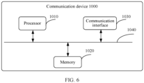
- FIG. 6 is a schematic diagram of a structure of a communication device 1000 according to an embodiment of this application.
- the communication device 1000 includes a processor 1010, a memory 1020, a communication interface 1030, and a bus 1040.
- the communication interface 1030 in the communication device 1000 shown in FIG. 6 may be used for communication with another device.
- the processor 1010 may be connected to the memory 1020.
- the memory 1020 may be configured to store program code and data. Therefore, the memory 1020 may be an internal storage module of the processor 1010, may be an external storage module independent of the processor 1010, or may be a component that includes an internal storage module of the processor 1010 and an external storage module independent of the processor 1010.
- the communication device 1000 may further include the bus 1040.
- the memory 1020 and the communication interface 1030 may be connected to the processor 1010 through the bus 1040.
- the bus 1040 may be a peripheral component interconnect (Peripheral Component Interconnect, PCI) bus, an extended industry standard architecture (Extended Industry Standard Architecture, EISA) bus, or the like.
- PCI peripheral component interconnect
- EISA Extended Industry Standard Architecture
- the bus 1040 may be classified into an address bus, a data bus, a control bus, or the like. For ease of representation, only one line is used for representation in FIG. 6 , but this does not mean that there is only one bus or only one type of bus.
- the processor 1010 may be a central processing unit (central processing unit, CPU).
- the processor may be alternatively a general-purpose processor, a digital signal processor (digital signal processor, DSP), an application-specific integrated circuit (application-specific integrated circuit, ASIC), a field programmable gate array (field programmable gate Array, FPGA) or another programmable logical device, a discrete gate or transistor logic device, or a discrete hardware component.
- the general-purpose processor may be a microprocessor, or the processor may be any conventional processor or the like.
- the processor 1010 uses one or more integrated circuits to execute a related program, to implement the technical solutions provided in embodiments of this application.
- the memory 1020 may include a read-only memory and a random access memory, and provides instructions and data to the processor 1010.
- a part of the processor 1010 may further include a non-volatile random access memory.
- the processor 1010 may further store device type information.
- the processor 1010 executes computer-executable instructions in the memory 1020 to perform the operation steps of the foregoing method.
- the communication device 1000 may correspond to a corresponding execution body of the method according to embodiments of this application, and the foregoing and other operations and/or functions of modules in the communication device 1000 are separately intended to implement corresponding procedures of the methods in the embodiments. For simplicity, details are not described herein again.
- the disclosed system, apparatus, and method may be implemented in another manner.
- the described apparatus embodiment is merely an example.
- division into the units is merely logical function division or may be other division in actual implementation.
- a plurality of units or components may be combined or integrated into another system, or some features may be ignored or not performed.
- the displayed or discussed mutual couplings or direct couplings or communication connections may be implemented through some interfaces.
- the indirect couplings or communication connections between the apparatuses or units may be implemented in electrical, mechanical, or another form.
- the units described as separate parts may or may not be physically separate, and parts displayed as units may or may not be physical units, may be located in one position, or may be distributed on a plurality of network units. Some or all of the units may be selected depending on actual requirements to achieve the objectives of the solutions of embodiments.
- function units in embodiments of this application may be integrated into one processing unit, or each of the units may exist alone physically, or two or more units are integrated into one unit.
- the functions When the functions are implemented in a form of a software functional unit and sold or used as an independent product, the functions may be stored in a computer-readable storage medium. Based on such an understanding, the technical solutions of this application essentially, or the part contributing to the current technology, or some of the technical solutions may be implemented in a form of a software product.
- the computer software product is stored in a storage medium, and includes several instructions for instructing a computer device (which may be a personal computer, a server, a network device, or the like) to perform all or some of the steps of the methods described in embodiments of this application.
- the storage medium includes any medium that can store program code, such as a USB flash drive, a removable hard disk, a read-only memory (Read-Only Memory, ROM), a random access memory (Random Access Memory, RAM), a magnetic disk, or a compact disc.
- program code such as a USB flash drive, a removable hard disk, a read-only memory (Read-Only Memory, ROM), a random access memory (Random Access Memory, RAM), a magnetic disk, or a compact disc.
- An embodiment of this application further provides a computer-readable storage medium, where a computer program is stored on the computer-readable storage medium, and when being executed by a processor, the program is used to perform a diversification issue generation method.
- the method includes at least one of solutions described in the foregoing embodiments.
- the computer storage medium may be any combination of one or more computer-readable media.
- the computer-readable medium may be a computer-readable signal medium or a computer-readable storage medium.
- the computer-readable storage medium may be but is not limited to an electric, magnetic, optical, electromagnetic, infrared, or semiconductor system, apparatus, or device, or any combination thereof.
- the computer-readable storage medium includes an electrical connection having one or more wires, a portable computer disk, a hard disk, a random access memory (RAM), a read-only memory (ROM), an erasable programmable read-only memory (EPROM or flash memory), an optical fiber, a portable compact disk read-only memory (CD-ROM), an optical storage device, a magnetic storage device, or any suitable combination thereof.
- the computer-readable storage medium may be any tangible medium including or storing a program that may be used by an instruction execution system, apparatus, or device, or be used in combination with an instruction execution system, apparatus, or device.
- a computer-readable signal medium may include a data signal propagated in a baseband or propagated as part of a carrier, where the data signal carries computer-readable program code. Such a propagated data signal may take a variety of forms, including but not limited to an electromagnetic signal, an optical signal, or any suitable combination thereof.
- the computer-readable signal medium may alternatively be any computer-readable medium other than the computer-readable storage medium.
- the computer-readable medium may send, propagate, or transmit the program used by the instruction execution system, apparatus, or device, or used in combination with the instruction execution system, apparatus, or device.
- the program code included in the computer-readable medium may be transmitted by using any suitable medium, including but not limited to wireless, a wire, an optical cable, RF, and the like, or any suitable combination thereof.
- Computer program code for performing the operations in this application may be written in one or more programming languages, or a combination thereof.
- the programming languages include an object-oriented programming language, such as Java, Smalltalk, and C++, and also include a conventional procedural programming language, such as a "C" language or a similar programming language.
- the program code may be executed entirely on a user computer, or some may be executed on a user computer as a separate software package, or some may be executed on a user computer while some is executed on a remote computer, or the code may be entirely executed on a remote computer or a server.
- the remote computer may be connected to a user computer by using any type of network, including a local area network (LAN) or a wide area network (WAN), or may be connected to an external computer (for example, connected by using an Internet service provider through the Internet).
- LAN local area network
- WAN wide area network
- an external computer for example, connected by using an Internet service provider through the Internet.
Landscapes
- Engineering & Computer Science (AREA)
- Computer Networks & Wireless Communication (AREA)
- Signal Processing (AREA)
- Mobile Radio Communication Systems (AREA)
Applications Claiming Priority (1)
| Application Number | Priority Date | Filing Date | Title |
|---|---|---|---|
| PCT/CN2020/132947 WO2022110221A1 (zh) | 2020-11-30 | 2020-11-30 | 通信方法及相关设备 |
Publications (2)
| Publication Number | Publication Date |
|---|---|
| EP4236592A1 true EP4236592A1 (de) | 2023-08-30 |
| EP4236592A4 EP4236592A4 (de) | 2024-01-10 |
Family
ID=81753914
Family Applications (1)
| Application Number | Title | Priority Date | Filing Date |
|---|---|---|---|
| EP20963109.2A Pending EP4236592A4 (de) | 2020-11-30 | 2020-11-30 | Kommunikationsverfahren und zugehörige vorrichtung |
Country Status (4)
| Country | Link |
|---|---|
| US (1) | US20230308977A1 (de) |
| EP (1) | EP4236592A4 (de) |
| CN (1) | CN116406526B (de) |
| WO (1) | WO2022110221A1 (de) |
Families Citing this family (2)
| Publication number | Priority date | Publication date | Assignee | Title |
|---|---|---|---|---|
| CN114916026B (zh) * | 2022-06-29 | 2023-10-13 | Oppo广东移动通信有限公司 | 小区切换方法与装置、终端设备 |
| CN120224311A (zh) * | 2024-07-11 | 2025-06-27 | 荣耀终端股份有限公司 | 一种被用于无线通信的通信节点中的方法和装置 |
Family Cites Families (9)
| Publication number | Priority date | Publication date | Assignee | Title |
|---|---|---|---|---|
| US10917932B2 (en) * | 2016-09-26 | 2021-02-09 | Samsung Electronics Co., Ltd. | Method and apparatus for communication in next generation mobile communication system |
| US20200214070A1 (en) * | 2017-06-14 | 2020-07-02 | Samsung Electronics Co., Ltd | Method and user equipment (ue) for reconnecting rrc connection with radio access network (ran) node |
| US11218880B2 (en) * | 2017-06-26 | 2022-01-04 | Telefonaktiebolaget Lm Ericsson (Publ) | Control signaling in a wireless communication system |
| CN109391362B (zh) * | 2017-08-11 | 2022-07-29 | 中兴通讯股份有限公司 | 一种信令传输方法及装置 |
| JP2019121828A (ja) * | 2017-12-28 | 2019-07-22 | シャープ株式会社 | 端末装置、基地局装置、通信方法、および、集積回路 |
| MX2020013295A (es) * | 2018-06-15 | 2021-02-22 | Guangdong Oppo Mobile Telecommunications Corp Ltd | Metodo para comunicar informacion de medicion, metodo para configurar dispositivo de terminal y dispositivo. |
| CN113207153B (zh) * | 2018-10-23 | 2022-08-16 | Oppo广东移动通信有限公司 | 一种控制终端移动性的方法及装置、终端 |
| EP3900434B1 (de) * | 2018-12-19 | 2023-10-25 | Telefonaktiebolaget LM Ericsson (publ) | Unterbrechung-wiederaufnahme bei bedingter übergabe |
| CN109819491B (zh) * | 2019-03-21 | 2021-07-06 | 创新维度科技(北京)有限公司 | 切换控制方法、基站和存储介质 |
-
2020
- 2020-11-30 WO PCT/CN2020/132947 patent/WO2022110221A1/zh not_active Ceased
- 2020-11-30 CN CN202080106499.8A patent/CN116406526B/zh active Active
- 2020-11-30 EP EP20963109.2A patent/EP4236592A4/de active Pending
-
2023
- 2023-05-26 US US18/202,816 patent/US20230308977A1/en active Pending
Also Published As
| Publication number | Publication date |
|---|---|
| US20230308977A1 (en) | 2023-09-28 |
| CN116406526A (zh) | 2023-07-07 |
| WO2022110221A1 (zh) | 2022-06-02 |
| EP4236592A4 (de) | 2024-01-10 |
| CN116406526B (zh) | 2025-08-08 |
Similar Documents
| Publication | Publication Date | Title |
|---|---|---|
| CN109168179B (zh) | 一种系统双连接调度方法及装置 | |
| EP4024941A1 (de) | Verfahren zum messen der erfahrungsqualität und kommunikationsgerät | |
| JP6463781B2 (ja) | D2d通信における動作モードの切替え | |
| TWI376165B (en) | Methods for handling measurement reports in a wireless communication system | |
| EP3537789A1 (de) | Funkrufverfahren, basisstation und endgerät | |
| CN104272804B (zh) | 测量方法、测量控制方法及设备 | |
| WO2017041274A1 (zh) | 信道测量与测量结果上报的方法和装置 | |
| US20230308977A1 (en) | Communication Method and Related Device | |
| EP4142423A1 (de) | Informationsübertragungsverfahren, endgerät und netzwerkvorrichtung | |
| US20240098538A1 (en) | Rrm measurement activity reporting and usage | |
| JP7842235B2 (ja) | 通信方法および装置 | |
| WO2020156187A1 (zh) | 一种小区测量方法及装置 | |
| CN114916026B (zh) | 小区切换方法与装置、终端设备 | |
| JP2020508620A (ja) | ハンドオーバ方法及びシステム並びにデバイス | |
| WO2018082054A1 (zh) | 通信方法及通信设备 | |
| WO2019228459A1 (zh) | 通信方法、装置及存储介质 | |
| CN117202227A (zh) | Sdt事件记录方法、装置及存储介质 | |
| JP6874024B2 (ja) | 情報伝送方法及び装置 | |
| CN117835459B (zh) | 通信方法、终端设备、存储介质、芯片系统及产品 | |
| EP4080913A1 (de) | Kommunikationsverfahren und -vorrichtung | |
| JP2023010465A (ja) | ユーザ装置、基地局及び通信制御方法 | |
| EP3198901B1 (de) | Vorrichtungsentdeckung in einer vorrichtung-zu-vorrichtung-kommunikation unter verwendung von zwei arten der entdeckung | |
| CN111225412B (zh) | 确定网络设备状态的方法和装置 | |
| CN114143292B (zh) | 策略更新方法、装置及可读存储介质 | |
| WO2023282352A1 (ja) | 通信装置、基地局及び通信方法 |
Legal Events
| Date | Code | Title | Description |
|---|---|---|---|
| STAA | Information on the status of an ep patent application or granted ep patent |
Free format text: STATUS: THE INTERNATIONAL PUBLICATION HAS BEEN MADE |
|
| PUAI | Public reference made under article 153(3) epc to a published international application that has entered the european phase |
Free format text: ORIGINAL CODE: 0009012 |
|
| STAA | Information on the status of an ep patent application or granted ep patent |
Free format text: STATUS: REQUEST FOR EXAMINATION WAS MADE |
|
| 17P | Request for examination filed |
Effective date: 20230526 |
|
| AK | Designated contracting states |
Kind code of ref document: A1 Designated state(s): AL AT BE BG CH CY CZ DE DK EE ES FI FR GB GR HR HU IE IS IT LI LT LU LV MC MK MT NL NO PL PT RO RS SE SI SK SM TR |
|
| REG | Reference to a national code |
Ref country code: DE Ref legal event code: R079 Free format text: PREVIOUS MAIN CLASS: H04W0076270000 Ipc: H04W0076300000 |
|
| A4 | Supplementary search report drawn up and despatched |
Effective date: 20231212 |
|
| RIC1 | Information provided on ipc code assigned before grant |
Ipc: H04W 76/27 20180101ALN20231206BHEP Ipc: H04W 36/00 20090101ALI20231206BHEP Ipc: H04W 76/30 20180101AFI20231206BHEP |
|
| DAV | Request for validation of the european patent (deleted) | ||
| DAX | Request for extension of the european patent (deleted) | ||
| RIC1 | Information provided on ipc code assigned before grant |
Ipc: H04W 76/30 20180101AFI20260303BHEP Ipc: H04W 36/00 20090101ALI20260303BHEP Ipc: H04W 76/27 20180101ALN20260303BHEP |
|
| GRAP | Despatch of communication of intention to grant a patent |
Free format text: ORIGINAL CODE: EPIDOSNIGR1 |
|
| STAA | Information on the status of an ep patent application or granted ep patent |
Free format text: STATUS: GRANT OF PATENT IS INTENDED |
|
| RIC1 | Information provided on ipc code assigned before grant |
Ipc: H04W 76/30 20180101AFI20260323BHEP Ipc: H04W 36/00 20090101ALI20260323BHEP Ipc: H04W 76/27 20180101ALN20260323BHEP |
|
| INTG | Intention to grant announced |
Effective date: 20260413 |