EP4236676B1 - Dispositif de travail - Google Patents
Dispositif de travail Download PDFInfo
- Publication number
- EP4236676B1 EP4236676B1 EP21830706.4A EP21830706A EP4236676B1 EP 4236676 B1 EP4236676 B1 EP 4236676B1 EP 21830706 A EP21830706 A EP 21830706A EP 4236676 B1 EP4236676 B1 EP 4236676B1
- Authority
- EP
- European Patent Office
- Prior art keywords
- jaw
- work device
- moveable
- moveable jaw
- grab
- Prior art date
- Legal status (The legal status is an assumption and is not a legal conclusion. Google has not performed a legal analysis and makes no representation as to the accuracy of the status listed.)
- Active
Links
Images





Classifications
-
- A—HUMAN NECESSITIES
- A01—AGRICULTURE; FORESTRY; ANIMAL HUSBANDRY; HUNTING; TRAPPING; FISHING
- A01G—HORTICULTURE; CULTIVATION OF VEGETABLES, FLOWERS, RICE, FRUIT, VINES, HOPS OR SEAWEED; FORESTRY; WATERING
- A01G23/00—Forestry
- A01G23/02—Transplanting, uprooting, felling or delimbing trees
- A01G23/06—Uprooting or pulling up trees; Extracting or eliminating stumps
-
- A—HUMAN NECESSITIES
- A01—AGRICULTURE; FORESTRY; ANIMAL HUSBANDRY; HUNTING; TRAPPING; FISHING
- A01G—HORTICULTURE; CULTIVATION OF VEGETABLES, FLOWERS, RICE, FRUIT, VINES, HOPS OR SEAWEED; FORESTRY; WATERING
- A01G23/00—Forestry
- A01G23/02—Transplanting, uprooting, felling or delimbing trees
- A01G23/06—Uprooting or pulling up trees; Extracting or eliminating stumps
- A01G23/062—Pulling up trees or stumps
-
- E—FIXED CONSTRUCTIONS
- E02—HYDRAULIC ENGINEERING; FOUNDATIONS; SOIL SHIFTING
- E02F—DREDGING; SOIL-SHIFTING
- E02F3/00—Dredgers; Soil-shifting machines
- E02F3/04—Dredgers; Soil-shifting machines mechanically-driven
- E02F3/28—Dredgers; Soil-shifting machines mechanically-driven with digging tools mounted on a dipper- or bucket-arm, i.e. there is either one arm or a pair of arms, e.g. dippers, buckets
- E02F3/36—Component parts
- E02F3/40—Dippers; Buckets ; Grab devices, e.g. manufacturing processes for buckets, form, geometry or material of buckets
- E02F3/402—Dippers; Buckets ; Grab devices, e.g. manufacturing processes for buckets, form, geometry or material of buckets with means for facilitating the loading thereof, e.g. conveyors
- E02F3/404—Dippers; Buckets ; Grab devices, e.g. manufacturing processes for buckets, form, geometry or material of buckets with means for facilitating the loading thereof, e.g. conveyors comprising two parts movable relative to each other, e.g. for gripping
-
- E—FIXED CONSTRUCTIONS
- E02—HYDRAULIC ENGINEERING; FOUNDATIONS; SOIL SHIFTING
- E02F—DREDGING; SOIL-SHIFTING
- E02F3/00—Dredgers; Soil-shifting machines
- E02F3/04—Dredgers; Soil-shifting machines mechanically-driven
- E02F3/28—Dredgers; Soil-shifting machines mechanically-driven with digging tools mounted on a dipper- or bucket-arm, i.e. there is either one arm or a pair of arms, e.g. dippers, buckets
- E02F3/36—Component parts
- E02F3/40—Dippers; Buckets ; Grab devices, e.g. manufacturing processes for buckets, form, geometry or material of buckets
- E02F3/413—Dippers; Buckets ; Grab devices, e.g. manufacturing processes for buckets, form, geometry or material of buckets with grabbing device
- E02F3/4135—Dippers; Buckets ; Grab devices, e.g. manufacturing processes for buckets, form, geometry or material of buckets with grabbing device with grabs mounted directly on a boom
-
- E—FIXED CONSTRUCTIONS
- E02—HYDRAULIC ENGINEERING; FOUNDATIONS; SOIL SHIFTING
- E02F—DREDGING; SOIL-SHIFTING
- E02F3/00—Dredgers; Soil-shifting machines
- E02F3/04—Dredgers; Soil-shifting machines mechanically-driven
- E02F3/96—Dredgers; Soil-shifting machines mechanically-driven with arrangements for alternate or simultaneous use of different digging elements
- E02F3/965—Dredgers; Soil-shifting machines mechanically-driven with arrangements for alternate or simultaneous use of different digging elements of metal-cutting or concrete-crushing implements
Definitions
- the invention concerns a work device.
- stump-grubbing harrows are known. They are intended to scrape ground to loosen stumps, root clumps, and stones, for example, when clearing land for cultivation.
- Stump-grubbing harrows can be attached, for example, to the end of set of booms of an excavator, the harrow being operated by using the set of booms. If necessary, a stump-grubbing harrow can also be used for scarifying.
- a stump-grubbing harrow is typically formed of set of curved claws arranged in rows, using the points of which the aforementioned operations are carried out.
- a stump-grubbing harrow cannot be used to perform, for example, effective and precise materials handling, i.e., for example, moving objects from one place to another.
- stump harvester is designed especially for stump lifting and particularly for chopping them. It can be used to lift stumps from the ground and/or to chop them already in the ground or when lifted from it.
- the stump harvester is formed, for example, of two fixed claws arranged next to each other with a claw moveable against them, which is arranged to go between the fixed claws.
- the cutting claw thus acts as a moveable jaw and also as a blade.
- the object, i.e. the stump, or part of it intended to be processed by the device can be pressed between the moveable claw and the fixed claws.
- the stump harvester can also be used to break up tussocks.
- a fixed tussocking element is integrated on the opposite side of the fixed claws to the moveable claw. It can be used to push the ground open.
- stump harvester is known from Finnish patent application publication number FI 780836 A .
- Stump harvesters are characterized by a great power output requirement.
- the same also applies to various crushing grabs, in which in addition to a moveable jaw, crushing is often further boosted by an impact device implemented, for example, as a hydraulic hammer.
- the great power output is obtained using a moment arm. This is located between the end of the operating element of the hydraulic actuator and the moveable claw.
- An adjustable moment is obtained by means of a moment arm arranged with a changeable angle attitude.
- stump harvesters can only be used to perform the effective and precise processing of stumps. Examples of other work are the lifting and transfer of stones from one place to another. Which is even less successful using a crushing grab.
- grabs which are also called grab buckets, are also known. They are intended especially for material handling. They include two moveable jaws, which can be arranged opposite each other. Both of the jaws are then pivoted rotatably, so that the grab can be closed and opened.
- the grab is typically used to grip the object to be handled, move it to another location, and release the object. The object to be moved is thus gripped by the grab, and pressed between its jaws.
- the grab cannot, however, be used, for example, to effectively handle stumps, such as lifting them, or for soil tilling.
- AU717522B2 , AU2016203401A1 and US7617619B2 disclose different examples of multi-purpose work devices with different types of grabs.
- the invention is intended to create a multi-purpose work device.
- the characteristic features of the work device according to the invention are stated in Claim 1.
- the work device according to the invention can be said to be suitable not only for compromise-free grab operation, but also for tearing, separating, and demolition, for collecting the material being handled without grab operation, and even for soil tilling.
- This is all made possible by the fixed jaw and the jaw arranged to move relative to it, arranged to form a grab.
- the fixed jaw can be made sufficiently strong, for example, for soil tilling and material handling take place by "shovelling", i.e. for transfer taking place by pushing the material.
- the moveable jaw can, in turn, be narrower than the fixed jaw. This improves the visibility of the material being processed and the processing object.
- the moveable jaw can, if necessary, be turned out of the way when not needed, using an arm mechanism arranged for it, making unobstructed operations with the fixed jaw of the work device possible.
- the moveable jaw can even be turned out of the way in a selected direction.
- the work device includes a wide-angle pivot setup for the moveable jaw.
- This is implemented by an arm mechanism equipped with two pivots between the hydraulic actuator and the moveable jaw.
- the arm mechanism with two pivots is then arranged to form a wide-angle pivot.
- the magnitude of the rotation angle of the movement created for the jaw arranged to move by the wide-angle pivot is more than 120°.
- the straight movement created by the hydraulic actuator is converted into a wide rotation movement of the moveable jaw with the aid of the wide-angle pivot setup, which, the arm mechanism equipped with two pivots is arranged to form. Thanks to the arm mechanism, more generally the wide-angle pivot setup, the moveable jaw, for example, from its base part, is made even mainly parallel to the hydraulic actuator, at both extreme ends of the movement of the jaw. This is when the grab is fully opened as an extension of the hydraulic actuator as well as also when the grab is fully closed and mainly parallel to the hydraulic actuator.
- the wide-angle pivot setup includes, in addition to an arm mechanism equipped with two pivots, the jaw arm, a lever arm arranged to rotate.
- the lever arm is fitted between the jaw arm and the body, to change the movement of the moving operating element of the hydraulic actuator into a rotational movement of the jaw arranged to move.
- the lever arm is pivoted to the body of the device.
- the lever arm is pivoted at the other end to the same pivot point from which the jaws arm is attached to the operating element of the hydraulic actuator.
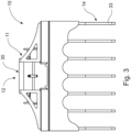
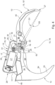
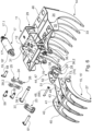
- Figures 1 - 3 show an example of the work device 10 according to the invention.
- Figure 1 shows an angled view of the work device 10,
- Figure 2 a top view of it, and
- Figure 3 a side view seen from the side of the fixed jaw 14.
- the work device 10 includes, as basic parts, a body 11, a pair of jaws 13 arranged to form a grab 16, and a hydraulic actuator 17 for the grab 16, i.e. for opening and closing it.
- the body 11 of the work device 10 is equipped with an attachment arrangement 12 to arrange the work device 10 at the end of a set of booms of the work machine (not shown).
- the work machine can be, for example, an excavator.
- the end of the set of booms of the excavator can be equipped, in an as such known manner, with a bucket rotation set of arms and an attachment interface for a work device.
- the set of booms includes, as is known, a main boom pivoted to the work machine, with an arm pivoted at its end, which is also often called an excavating arm. At its end is the attachment interface of the work device 10, or at least part of it. At the end of the set of booms there can be a possible selected quick connector.
- the work tool such as, for example, a bucket, or now, in the case of the invention, a work device 10 according to the invention, can be detachably connected by its counter-piece to the quick connector, for example, without tools, and without the operator leaving the cab.
- the quick connector can be arranged directly in the pivot points of the bucket rotation at the end of the set of booms. On the other hand, it can also be in, for example, a rotator or a combination of a bucket rotator and a tilt, i.e. in a rototilt, as a part of them.
- the attachment arrangement 12 can, of course, also be fitted directly to the rotator, i.e. with no special adapters.
- the body 11 is arranged to form a casing structure 29.
- the casing structure 29 can be, for example, of sheet metal work. There can be stiffening casing beams in it.
- the opening arrangement 31 is arranged to be such that it is suitable for two or more quick-release attachment adapters, i.e. their counter-pieces to be connected to the work device 10.
- Each counter-piece of adapter model can have its own opening in the opening arrangement 31.
- the counter-piece is to be attached to the openings by, for example, bolts.
- several different adapter models can be arranged for the work device 10, with numerous different types available for excavators, or alternatively also for direct attachment to rotators, equipped with, for example, tilting.
- a pair of jaws 13 is fitted to the body 11 of the work device 10.
- the pair of jaws 13 includes two jaws 14, 15 arranged to form a grab 16. Both of the jaws 14, 15 are now curved.
- the first of the jaws 14 forming the pair of jaws 13 of the grab 16 is fitted permanently in the body 11, i.e. immovably relative to the body 11.
- the body 11 continues in the lateral direction of the work device 10, as a sheet-metal structure 32 on both sides of the casing structure 29.
- the curved claws 33 belonging to the fixed jaw 14 are joined to the sheet-metal structure 32 at their roots 34.
- the roots 34 can also be termed the cheek plate of the jaw 14.
- the roots 34 can include an extension 35, 35' arranged to continue under the body 11.
- the extension 35, 35' is one way to continue the reach of the inner curve 54 of the jaw 14 over most of the grab 16 from its upper part.
- the share of the fixed jaw 14 is arranged to be more than half of the grab 16.
- the inner curve 54 of the fixed jaw 14 is arranged to extend over most of the body 11.
- the extensions 35, 35' can form zones laterally in the grab 16. In the middle of the grab 16, for example, in the area of the moving jaw 15, the extension 35' can be lower, thus forming a larger space in bottom of the grab 16 ( Figures 4 and 5 ).
- the extensions 35 can, in turn, be higher ( Figures 1 and 6 ) than in the middle area.
- the larger space in the middle of the grab 16 facilitates, for example, handling stones.
- the higher extension 35 at the sides of the grab 16 in turn facilitates handling longer objects (e.g., planks or pipes).
- the other jaw 15, arranged to form the grab 16, is pivoted rotatably to the body 11, to open and close the grab 16.
- the jaw 15 is fitted moveably to the grab 16 and body 11.
- the movement is created by a hydraulic actuator 17.
- the jaw 15 is rotated relative to the rotation pivot 22 arranged in the work device 10.
- the fixing and integration of the other jaw 14 even as part of the actual body 11 creates a strong body for the work device 10.
- the grab 16 will then withstand even violent torsion and hard work.
- pivot-point openings 36.1, 36.2 for the moveable jaw 15 in the body 11 of the work device 10 and in the moveable jaw 15 (or in the quick connector 47, Figure 8a , fitted rotatably for it in the body 11), through which pivoting is achieved ( Figures 6 and 7 ).
- the jaw 15 is connected to the body 11 (and to the aforesaid quick connector 47 arranged rotatably with it) by the pivot pin 37 ( Figures 6 and 7 ) running through the openings 36.1, 36.2.
- the openings 36.1 are in lug plates 76 protruding from the body 11.
- the hydraulic actuator 17 is equipped with a moving operating element 19.
- the operating element 19 is formed by a piston rod 19', arranged to move back and forwards in the hydraulic actuator 17.
- the piston at its end is arranged to move back and forwards inside its cylinder part 17*, due to the effect of a pressure medium, such as, for example, a liquid.
- a pressure medium such as, for example, a liquid.
- the hydraulic actuator 17 is attached, in this case by its cylinder part 17*, by a pin 58 ( Figure 6 ) to a loop in the body 11 of the work device 10.
- the operating element 19, i.e. now the piston rod 19' is arranged to act on the moveable jaw 15, to open and close the grab 16.
- the operating element 19, more generally the hydraulic actuator 17, is arranged to act on one of the jaws 15 of the pair of jaws 13 forming the grab 16, by means of a wide-angle pivot setup 53 belonging to the work device 10.
- the rotation angle of the movement created by the wide-angle pivot setup 53 for the moveable jaw 15, has a magnitude of more than 120°.
- the angle can be defined from the moveable jaw 15, for example, with the aid of two selected fixed points.
- the fixed points form straight lines and the angle between the straight lines is measured when the jaw 15 is in its extreme positions.
- the wide-angle pivot setup 53 can be formed by an arm mechanism 18 equipped with at least two pivots 20, 21.
- the arm mechanism 18 for opening and closing the grab 16, by the movement of the moving operating element 19 of the hydraulic actuator 17, is between the moving operating element 19 of the hydraulic actuator 17 and the moveable jaw 15.
- to the moveable jaw 15 is arranged to be acted through the arm mechanism 18.
- the moving operating element 19 of the hydraulic actuator 17 is not attached directly through a single pivot to the moveable jaw 15, instead it is arranged to act on the moveable jaw 15 through the wide-angle pivot setup 53, i.e., in the embodiment described, through the arm mechanism 18.
- Action through the arm mechanism 18 can also be termed indirect.
- An advantage of the arm mechanism 18, more generally, of the wide-angle pivot setup 53 is the large rotation movement created for the moveable jaw 15, i.e. the large opening of the grab 16 ( Figure 4 ) and also of the closing of the grab 16, i.e. the rotation of the moveable jaw 15 to the roots of the fixed jaw ( Figure 5 ).
- the wide-angle pivot setup 53 is arranged to create a rotation movement, i.e. a movement range, of the moveable jaw 15, of a magnitude of, for example, 120° - 180°, 140° - 180°, more particularly 150° - 180°, and even more particularly 160° - 180°.
- the movement range of the moveable jaw 15 of the work device 10 shown as a one example is stated as a rotation angle of 170°, which can be seen in Figures 4 , 5 and especially in Figure 12 .
- the angle can be measured, for example, using as an aid a straight line drawn through the rotation pivot 22 of the jaw 15 and the tubular shaft 43, when the jaw 15 is in its extreme positions, i.e., the grab 16 fully open (15 o , Figure 12 ) and the grab 16 fully closed (15 c , Figure 12 ).
- the arm mechanism 18 equipped with two pivots 20, 21 is one example of how to arrange a wide-angle pivot for the moveable jaw 15.
- the moveable jaw 15 can then be implemented with very compact dimensions. In other words, it can be implemented, for example, without special elbows or lugs protruding from it, which could, for example, interfere with the operation of the work device 10 and/or visibility, or could also increase the weight or imbalance of the work device 10.
- the hydraulic actuator 17 can also be relatively short, to create a large movement for the moveable jaw 15.
- the stroke of the operating element 19 of the hydraulic actuator 17 arranged to move can be, despite the large movement range of the jaw 15, only 150 - 300 mm.
- the maximum opening of the grab 16, i.e. the greatest distance between the points of the claws 33, 40 of the jaws 14, 15 when the moveable jaw 15 is in the extreme position and the grab 16 is thus open, is, for with the order of size of the work device 10 according to the example, 1300 - 1500 mm.
- the opening can vary according to the order of size.
- the arm mechanism 18 and its pivots 20, 21 are arranged in such a way that the farthest pivot 21 of the arm mechanism 18 relative to the hydraulic actuator 17 and, more especially to its operating element 19 arranged to move, can be arranged to move behind the rotation pivot 22 of the moveable jaw 15, in the extreme position of the moveable jaw 15.
- This extreme position is when the grab 16 is fully closed ( Figure 5 ).
- the claws 40 of the moveable jaw 15 are arranged to intermesh with the claws 33 of the fixed jaw 14.
- the grab 16 can then be completely closed as the jaws 14, 15 intermesh with each other.
- the rotation pivot 22 of the moveable jaw 15 is between the hydraulic actuator 17 and the pivot 21, arranged in connection with the moveable jaw 15, which belongs to the arm mechanism 18.
- Figure 5 shows this situation. This is only one example of a way to define both the implementation of the arm mechanism 18 and also the setup of the wide-angle pivot 53 and movement in connection with the invention.
- the arm mechanism 18 includes a jaw arm 23, including two pivots 20, 21.
- the jaw arm 23 is arranged to rotate the moveable jaw 15, with the linear movement of the moving operating element 19 of the hydraulic actuator 17.
- the jaw arm 23 can be formed of two adjacent arms connected to the pivot points. At its first end, the jaw arm 23 is pivoted to the hydraulic actuator 17 and now most particularly to the loop fitted to the end of its moving operating element 19. At the other, opposite end, the jaw arm 23 is pivoted to the moveable jaw 15. In the jaw 15 there is an opening 38 in its base part 28 (or in the quick-release connector 47 of the jaw 15) for a pivot 21, implemented once again an adjacent pair of openings.
- the pivot 21 is in the base part 28 of the jaw 15 (or in the quick connector 47 of the jaw 15), at a distance from the rotation pivot 22 of the jaw 15. If either a pushing or pulling movement is directed, by the moving operating element 19 of the hydraulic actuator 17, through the jaw arm 23 to the pivot point 21 of the jaw arm 23 fitted to the base part 28, the jaw 15 is forced to rotate relative to its rotation pivot 22, thus either opening or closing the grab 16.
- the jaw arm 23 is arranged to be curved, to form a turning rod to the moveable jaw 15.
- the hydraulic actuator 17 can then be located mainly horizontally in the body 11 of the work machine 10 and nevertheless achieve a very wide motion range for the moving jaw 15, especially for closing the grab 16, i.e. for bringing it out of the way, intermeshed by the fixed jaw 14.
- the hydraulic actuator 17 is then shielded inside the casing structure 29.
- the jaw arm 23 then rotates behind the rotation pivot 22 of the moving jaw 15 as the grab 16 closes.
- the rotation pivot 22 is then located on the concave side of the curved jaw arm 23. This rotation is very clearly seen, for example, in Figure 11 .
- the arm mechanism 18 also includes a rotatable lever arm 24.
- the lever arm 24 is fitted between the jaw arm 23 and the body 11.
- the lever arm 24 is now used to ensure that the movement of the jaw arm 23 created by the operating element 19 of the hydraulic actuator 17 arranged to move, is arranged to be converted into a rotational movement of the moveable jaw 15.
- the lever arm 24 is arranged to act on the jaw arm 23.
- the lever arm 24 then controls the movement of the jaw arm 23 in such a way that the jaw arm 23 is not able to rotate relative to the jaw 15 without the jaw 15 rotating at the same time.
- the lever arm 24 is used to ensure that the jaw arm 23 acts over the entire motion range as an element either pushing or pulling the jaw 15. I.e.
- the lever arm 24 also protects the actuator 17 in the wide-angle pivot setup 53. Due to it, the motion of the operating element 19 of the actuator 17 is certain to be kept straight the whole time, despite the large rotation angle of the jaw 15, and no torsion acts on it, in which case the operating device 17 would be strained or possibly even break.
- the lever arm 24 is equipped with pivoting 25, 26, now fitted to the operating element 19 of the hydraulic actuator 17 arranged to move, and to the body 11.
- the lever arm 24 can also be formed of two adjacent arms. There are pivot openings 39.1, 39.2 for the pivoting 25, 26, in the ends of the lever arm 24.
- the pivoting 25 to the moving operation element 19 of the hydraulic actuator 17 takes place by a pin 59 from a loop at its end.
- a pivot opening 45 for example, arranged to a lug 64 for the pivoting 26 of the lever arm 24 to the body 11, using a pin 60 ( Figures 3 , 6 , and 7 ).
- the pivots 20, 21, 25, 26 belonging to the arm mechanism 18 can now also be said, in the case according to the embodiment described, to be fitted to the triangular geometry.
- the triangle is then formed between the pivots 20 (25), 21, 26 of the arm mechanism 18.
- the lever arm 24 can also be fitted to pivot to some point on the jaw arm 23, instead of the operating element 19. However, this leads to one additional pivot in the wide-angle pivot setup 53 according to the embodiment described.
- the implementation of the arm mechanism 18, particularly in the placing of the pivots 21, 22, can also be defined by straight distances D1, D2 from the point 27 of the moveable jaw 15 to the pivots 21, 22 ( Figure 4 ) fitted to the base part 28 at its opposite end.
- the distance D1 from the points 27 of the moveable jaw 15 to the pivot 21 fitted to the moveable jaw 15 for the jaw arm 23, is greater than the corresponding distance D2 from the points 27 of the moveable jaw 15 to the rotation pivot 22 of the jaw 15.
- the width W1 of the moveable jaw 15 can be 10 - 60 % of the width W2 ( Figure 1 ) of the fixed jaw 14. Besides this improving the visibility of the grab 16, the grab 16 is also made lighter.
- the wider fixed jaw 14 is very suitable, for example, for raking, stump lifting, and other soil-tilling work, in which the work device 10 is used without the moveable jaw 15. This is also helped by the wide-angle movement of the moveable jaw 15. Thanks to the invention, it can be turned well clear, even in both directions, when not needed.
- the moveable jaw 15, which is narrower than the fixed jaw 14, is also not so liable to be caught in obstacles, for example, in demolition work.
- One way to implement the structure of the moveable jaw 15 is to connect its pointed 27 claws 40 from the side surfaces of the base 41 by plate flanges.
- the moveable jaw 15 there are two or more claws 40, i.e. working widths, for example for gripping objects with the grab 16.
- the roots 41 of the claws 40 and the sheet metal-flanges 42 now join to the tubular beam 43.
- the implementation can, according to one embodiment, be such that an integral sheet-metal work piece 44, which is also called a quick connector 47 later in the description, in which the pivots of the moveable jaw 15 are fitted, i.e. the rotation pivot 22 of the moveable jaw 15 and the pivot 21 of the arm mechanism 18 in the side of the moveable jaw 15, can be fitted to the base part 28.
- the curve radius of the arm mechanism 18 of the moveable jaw 15, more particularly of the pivot 21 of its jaw arm 23, can be at a maximum the width of its base part 28.
- the sheet-metal work piece 44 can also act as an adapter, and even more particularly as a quick connector 47 for the moveable jaw 15, more generally for the moveable work element 15'.
- Figure 8a shows a first example of a quick connector 47 for the moveable work element 15'.
- attachment means 66 such as, for example, a pin 48.
- the pin 48 By means of the pin 48, it can be attached through openings 52 to holes 50 fitted to the attachment lugs 49 of the movable jaw 15.
- the quick connector 47 can also include downwardly opening hooks 51. The hooks 51 align and support in the jaw 15 the tubular beam 43 fitted to it.
- the moveable jaw 15 there can be, in the lugs 49 arranged as extensions of its middle-most claws 40, now in their lower parts, channel-like claws 68, of which the point of the one claw 68 appears in Figure 11 .
- the collars 62 of the rotation pivot 22 of the jaw 15 are arranged to align with these claws 68, when the moveable jaw 15 is attached to the quick connector 47 and thus to the work device 10.
- the claws 68 then oppose the outer surface 75 of the collars 62, which in this context can also be called the alignment surface 65.
- the claws 68 act as a kind of hanger 68'.
- the hook-like formations 51, 68 in the quick connector 47 and lugs 49 are opposite in these, when the jaw 15 is attached in the quick connector 47.
- the collars 67 and hooks 51 align the holes 52 and 50 in the quick connector 47 and lugs 49 with each other when fitted the work element 15' to the quick connector 47 and the attachment pin 48, i.e. the attachment means 66 is then easily put into the holes 52, 50 intended for it, and the work element 15' is attached to the quick connector 47 and through it to the body 11 of the work device 10.
- the outer surfaces 63 in the hooks 51 and collars 67 can be said to be alignment surfaces 65 to align the moveable jaw 15 with the quick connector 47 when attaching it to the work device 10.
- the quick connector 47 also includes an opening 52 for the attachment element 66, by which the moveable jaw 15 is arranged to be attached to the quick connector 47.
- Figure 8b shows the work device 10, equipped with a quick connector 47 according to another embodiment, without the moveable jaw 15.
- the quick connector 47 can be, when changing the work element 15' in it, fixed in the body 11 by a pin 37 in the rotation pivot 22 arranged in it, and by a pin 61 in the pivot 21 arranged for it in the jaw arm 23.
- Using the quick connector 47 permits the moveable jaw 15, for example, to be quickly exchanged for a stump-chopping blade or other work element, if so wished.
- the attachment mechanism now includes two small hydraulic cylinders 69.1, 69.2. They are placed between the pivot plates 70 belonging to the quick connector 47, being thus protected. There are now two hydraulic cylinders 69.1, 69.2, set in opposite directions to each other. There are attachment lugs 71 for them in the pivot plates 70, from which they are attached to the quick connector 47 by one end.
- Figure 8b shows only the option for such an operating device, i.e. in it there are only lugs 71 without cylinders and the jaw 15 is attached by a pin 48.
- this option is also realized, i.e. it includes the actual operating devices 69.1, 69.2 in the lugs 71.
- an operating element arranged to move back and forwards.
- the operating element can now act as an attachment means 66 creating locking.
- it can act directly as a locking pin 48, or indirectly act on a separate locking pin or mechanism.
- the quick connector 47 acting as an adapter further increases the versatility of the work device 10.
- the quick connector 47 permits the changing of the work element 15' with the detaching and replacement of only a single preferably smaller pin 48 relative to the pivots 21, 22. This accelerates changing one work element 15' for another.
- the attachment pin 48 is in an open place, relative to the pivots 21, 22, for its detaching and attaching.
- the pivots 21, 22 of the moveable jaw 15 could also be directly in the lugs 49 formed as extensions of its middle claws 40.
- a bulldozer blade 46 located on the rear side of the fixed jaw 14, i.e. on the opposite end to the claws 33. This can be used, for example, to level soil, i.e. the work device 10 can then also act as a drag. This property is useful, for example after stone lifting by the work device 10. The bulldozer blade 46 can then be used to level the site by filling the pit created.
- the hydraulic actuator 17 is a known double-acting liquid operated hydraulic cylinder, equipped with a single piston and piston rod.
- the hydraulic actuator 17 of the work device 10 can also be, for example, the variable force hydraulic cylinder formed by nesting operating elements, disclosed in the applicant's international patent application PCT/FI2017/050699 or PCT/FI2019/050287 . Using these, quick operation and, if necessary, also a great compressive force can be obtained for the grab 16 of the work device 10.
- FIGS 10 and 11 show yet another accessory for the work device 10 according to the invention.
- This is a bucket 55.
- the bucket 55 can be permanently joined to the fixed jaw 14. If the bucket 55 is threaded onto the claws 33 of the fixed jaw 14 by the lugs 57 fitted to it, like a glove on a hand, the bucket 55 is picked up by the work device 10 and remains in place by closing the grab 16, i.e. by pressing the moveable jaw 15 onto the bucket 55. For gripping, there are counter-pieces 56 in the bucket 55 for the moveable jaw 15. In other words, the moveable jaw 15 then presses the bucket 55 in place and also holds it in the grip of the grab 16, closed in contact with the fixed jaw 14. This too is aided by the wide-angle pivot setup 53.
- the bucket 55 can also be equipped, for example, with locks. Then, if needed, the bucket 55 can also remain in place, even if the moveable jaw 15 is used for normal work, i.e. even if it is not holding the bucket 55 in place.
- the moveable jaw 15 too can be equipped on the "glove principle", i.e. by a bucket that can be closed on the jaw 15 and/or an exchangeable bucket, which can be, for example, detachably attached to the quick connector 47.
- the work device 10 is very versatile. Thus in connection with the invention one can speak of a multi-purpose grab. Its application is not limited purely to gripping an object with jaws 14, 15 arranged to form a grab 16, instead it can be used to perform several other operations too. Examples are stump, stone, and root-lifting and raking, collecting material either with the grab 16 or then even with only a fixed jaw 14 (e.g., energy timber, stumps, branches, and stones) and soil tilling, and demolishing buildings. This means that there is no need to change tools 10 in a work machine, such as, for example, an excavator, between operations, instead all operations can be performed effectively and with high quality on one and the same run.
- a work machine such as, for example, an excavator
Landscapes
- Engineering & Computer Science (AREA)
- Mechanical Engineering (AREA)
- Structural Engineering (AREA)
- Mining & Mineral Resources (AREA)
- Civil Engineering (AREA)
- General Engineering & Computer Science (AREA)
- Life Sciences & Earth Sciences (AREA)
- Biodiversity & Conservation Biology (AREA)
- Ecology (AREA)
- Forests & Forestry (AREA)
- Environmental Sciences (AREA)
- Shovels (AREA)
- Jib Cranes (AREA)
- Financial Or Insurance-Related Operations Such As Payment And Settlement (AREA)
- Electrical Discharge Machining, Electrochemical Machining, And Combined Machining (AREA)
Claims (15)
- Dispositif de travail, qui comprend- un corps (11) équipé d'un agencement de fixation (12) pour agencer le dispositif de travail (10) au niveau d'une extrémité d'un ensemble de flèches d'un engin de chantier,- une paire de mâchoires (13) montées sur le corps (11), qui comprend deux mâchoires (14, 15) conçues pour former un grappin (16), parmi lesquelles la première des mâchoires (14) de la paire de mâchoires (13) formant ledit grappin (16) est montée de manière permanente sur le corps (11) et la seconde desdites mâchoires (15) est pivotée de façon rotative et séparément de l'agencement de fixation (12) au corps (11) afin d'ouvrir et de fermer ledit grappin (16),- des griffes (40, 33) montées sur les mâchoires (15, 14), les griffes (40) de la mâchoire mobile (15) étant conçues pour s'engrener avec les griffes (33) de la mâchoire fixe (14) afin d'amener la mâchoire mobile (15) à distance de la mâchoire fixe (14),- un vérin hydraulique (17) fixé par une extrémité (17.1) au corps (11) du dispositif de travail (10) et équipé d'un élément d'actionnement mobile (19), qui est conçu pour agir sur la mâchoire mobile (15) afin d'ouvrir et de fermer le grappin (16),- une configuration de pivots à grand angle (53) agencée sur le dispositif de travail (10) entre l'élément d'actionnement mobile (19) du vérin hydraulique (17) et la mâchoire mobile (15) afin d'ouvrir et de fermer le grappin (16) en utilisant uniquement la mâchoire mobile (15), laquelle configuration de pivots à grand angle (53) est conçue pour comprendreet dans lequel un angle de rotation du déplacement créé pour la mâchoire mobile (15) par ladite configuration de pivots à grand angle (53) a une amplitude supérieure à 120°.- un mécanisme de bras (18) équipé de deux pivots (20, 21) montés sur un bras de mâchoire (23), dans lequel ce dernier est conçu pour faire tourner la mâchoire mobile (15) par un déplacement linéaire de l'élément d'actionnement mobile (19) du vérin hydraulique (17),- un bras de levier rotatif (24) agencé entre le bras de mâchoire (23) et un organe pivotant (26) conçu de façon à ce que le corps (11) convertisse le déplacement de l'élément d'actionnement mobile (19) du vérin hydraulique (17) en un déplacement de rotation de la mâchoire mobile (15),
- Dispositif de travail selon la revendication 1, caractérisé en ce que le pivot plus éloigné (21) du mécanisme de bras (18) par rapport au vérin hydraulique (17), plus particulièrement par rapport à l'élément d'actionnement mobile (19) du vérin hydraulique (17), en liaison avec la mâchoire mobile (15), est destiné à être agencé, au moyen de ladite configuration de pivots à grand angle (53), par rapport à l'élément d'actionnement mobile (19) du vérin hydraulique (17), derrière un pivot de rotation (22) de la mâchoire mobile (15), dans une position extrême de la mâchoire mobile (15).
- Dispositif de travail selon la revendication 1 ou 2, caractérisé en ce que le bras de mâchoire (23) est conçu pour être courbé, afin de former une bielle vers la mâchoire mobile (15) .
- Dispositif de travail selon l'une quelconque des revendications 1 à 3, caractérisé en ce que le bras de levier (24) est équipé d'un organe pivotant (25, 26) monté sur l'élément d'actionnement mobile (19) du vérin hydraulique (17) et le corps (11) .
- Dispositif de travail selon l'une quelconque des revendications 1 à 4, caractérisé en ce qu'une course de l'élément d'actionnement mobile (19) du vérin hydraulique (17) est de 150 à 300 mm.
- Dispositif de travail selon l'une quelconque des revendications 1 à 5, caractérisé en ce qu'une distance (D1) entre des points (27) de la mâchoire mobile (15) et le pivot (21) agencé sur la mâchoire mobile (15) pour le bras de mâchoire (23) est supérieure à la distance correspondante (D2) entre des points (27) de la mâchoire mobile (15) et le pivot de rotation (22) de la mâchoire (15).
- Dispositif de travail selon l'une quelconque des revendications 1 à 6, caractérisé en ce que la configuration de pivots à grand angle (53) est conçue pour créer un déplacement de rotation dans la mâchoire mobile (15), dont l'amplitude est de 140° à 180°, plus particulièrement, de 150° à 180°, et encore plus particulièrement de 160° à 180°.
- Dispositif de travail selon l'une quelconque des revendications 1 à 7, caractérisé en ce que- une largeur (W1) de la mâchoire mobile (15) est de 10 à 60 % d'une largeur (W2) de la mâchoire fixe (14),- la mâchoire mobile (15) comprend au moins deux griffes (40) .
- Dispositif de travail selon l'une quelconque des revendications 1 à 8, caractérisé en ce que- la mâchoire mobile (15) comprend une partie de base (28) au niveau d'une extrémité opposée de la mâchoire (15) jusqu'au point (27) de la mâchoire (15), laquelle partie de base (28) est dépourvue d'ergots,- le pivot de rotation (22) de la mâchoire mobile (15) et le pivot (21) du mécanisme de bras (18) au niveau d'un côté de la mâchoire mobile (15) sont montés sur ladite partie de base sans ergots (28).
- Dispositif de travail selon l'une quelconque des revendications 1 à 9, caractérisé en ce qu'un rayon de courbure du pivot (21) du mécanisme de bras (18) monté sur la mâchoire mobile (15) est une largeur de la partie de base (28) appartenant à la mâchoire mobile (15).
- Dispositif de travail selon l'une quelconque des revendications 1 à 10, caractérisé en ce que le dispositif de travail (10) comprend un raccord rapide (47) pour fixer la mâchoire mobile (15) amovible au dispositif de travail (10), et sur ledit raccord rapide (47) sont montés- les pivots (21, 22) de la mâchoire mobile (15),- une ou plusieurs surfaces d'alignement (65) pour aligner la mâchoire mobile (15) par rapport au raccord rapide (47),- une ou plusieurs ouvertures (52) pour un élément de fixation (66), dans lequel la mâchoire mobile (15) est conçue pour être fixée au raccord rapide (47).
- Dispositif de travail selon la revendication 11, caractérisé en ce que- la mâchoire mobile (15) comprend un dispositif de suspension ouvert vers le haut (68'), qui est conçu pour s'aligner avec le collier (62) conçu pour cela dans le raccord rapide (47),- des crochets d'ouverture vers le bas (51) sont montés sur le raccord rapide (47), qui sont conçus pour s'aligner avec la barre tubulaire (43) appartenant à la mâchoire mobile (15).
- Dispositif de travail selon l'une quelconque des revendications 1 à 12, caractérisé en ce que- le corps (11) est conçu pour comprendre une structure de carter (29), à l'intérieur de laquelle est monté le vérin hydraulique (17),- l'agencement de fixation (12) est monté sur une surface supérieure (30) de la structure de carter (29).
- Dispositif de travail selon la revendication 13, caractérisé en ce que- le corps (11) comprend une structure en tôle (32) conçue pour s'étendre latéralement dans le dispositif de travail (10) de part et d'autre de la structure de carter (29),- la mâchoire fixe (14) comprend une base (34), depuis laquelle elle est conçue pour se raccorder à ladite structure en tôle (32).
- Dispositif de travail selon la revendication 14, caractérisé en ce que- la base (34) de la mâchoire fixe (14) comprend une extension (35, 35') conçue pour se prolonger sous le corps (11) pour étendre une portée d'une courbe interne (54) de la mâchoire fixe (14) depuis une partie supérieure du grappin (16),- les extensions (35, 35') appartenant au pied (34) de la mâchoire fixe (14) sont disposées dans des zones latéralement dans le grappin (16) de sorte que- dans une zone médiane du grappin (16), par exemple, dans la zone de la mâchoire mobile (15), l'extension (35') est plus basse, formant ainsi un espace plus grand dans le fond du grappin (16),- de part et d'autre de la mâchoire mobile (15), dans la direction latérale du grappin (16), les extensions (35) sont conçues pour être plus hautes que les extensions (35') montées sur la zone médiane du grappin (16).
Applications Claiming Priority (2)
| Application Number | Priority Date | Filing Date | Title |
|---|---|---|---|
| FI20206077A FI20206077A1 (fi) | 2020-10-29 | 2020-10-29 | Työlaite |
| PCT/FI2021/050739 WO2022090633A1 (fr) | 2020-10-29 | 2021-10-29 | Dispositif de travail |
Publications (3)
| Publication Number | Publication Date |
|---|---|
| EP4236676A1 EP4236676A1 (fr) | 2023-09-06 |
| EP4236676B1 true EP4236676B1 (fr) | 2024-11-20 |
| EP4236676C0 EP4236676C0 (fr) | 2024-11-20 |
Family
ID=79021594
Family Applications (1)
| Application Number | Title | Priority Date | Filing Date |
|---|---|---|---|
| EP21830706.4A Active EP4236676B1 (fr) | 2020-10-29 | 2021-10-29 | Dispositif de travail |
Country Status (8)
| Country | Link |
|---|---|
| US (1) | US20230399811A1 (fr) |
| EP (1) | EP4236676B1 (fr) |
| AU (1) | AU2021368017A1 (fr) |
| CA (1) | CA3196903A1 (fr) |
| FI (2) | FI20206077A1 (fr) |
| NZ (1) | NZ799638A (fr) |
| PL (1) | PL4236676T3 (fr) |
| WO (1) | WO2022090633A1 (fr) |
Family Cites Families (7)
| Publication number | Priority date | Publication date | Assignee | Title |
|---|---|---|---|---|
| AU717522B2 (en) * | 1996-12-13 | 2000-03-30 | Phillip V Bowman | Bucket clamp for excavator |
| US5865492A (en) * | 1997-01-07 | 1999-02-02 | Wec Company | Hydraulic grapple assembly with side rotation mechanism |
| US6176531B1 (en) * | 1998-11-16 | 2001-01-23 | Ronald E Wheeler | Grapple system |
| US6494515B1 (en) * | 2002-01-02 | 2002-12-17 | Carl D. Kalbfleisch | Pole handler attachment |
| US7617619B2 (en) * | 2007-10-31 | 2009-11-17 | Entek Manufacturing, Inc. | Prehensile bucket attachment |
| US9151012B2 (en) * | 2011-08-15 | 2015-10-06 | Paladin Brands Group, Inc. | Dual-mode thumb for excavator |
| AU2016203401A1 (en) * | 2015-05-28 | 2016-12-15 | Future Equipment Limited | Improvements relating to Root Rakes |
-
2020
- 2020-10-29 FI FI20206077A patent/FI20206077A1/fi unknown
-
2021
- 2021-10-29 AU AU2021368017A patent/AU2021368017A1/en active Pending
- 2021-10-29 NZ NZ799638A patent/NZ799638A/en unknown
- 2021-10-29 PL PL21830706.4T patent/PL4236676T3/pl unknown
- 2021-10-29 US US18/034,314 patent/US20230399811A1/en active Pending
- 2021-10-29 CA CA3196903A patent/CA3196903A1/fr active Pending
- 2021-10-29 FI FIU20214109U patent/FI13194Y1/fi active IP Right Grant
- 2021-10-29 WO PCT/FI2021/050739 patent/WO2022090633A1/fr not_active Ceased
- 2021-10-29 EP EP21830706.4A patent/EP4236676B1/fr active Active
Also Published As
| Publication number | Publication date |
|---|---|
| FI20206077A1 (fi) | 2022-04-30 |
| US20230399811A1 (en) | 2023-12-14 |
| AU2021368017A1 (en) | 2023-06-15 |
| PL4236676T3 (pl) | 2025-03-31 |
| WO2022090633A1 (fr) | 2022-05-05 |
| CA3196903A1 (fr) | 2022-05-05 |
| EP4236676A1 (fr) | 2023-09-06 |
| EP4236676C0 (fr) | 2024-11-20 |
| AU2021368017A9 (en) | 2025-03-27 |
| FI13194Y1 (fi) | 2022-05-19 |
| NZ799638A (en) | 2025-12-19 |
Similar Documents
| Publication | Publication Date | Title |
|---|---|---|
| US4845867A (en) | Triple-purpose attachment | |
| AU775711B2 (en) | Apparatus for excavating and crushing tree stumps | |
| US8221049B1 (en) | Independent hydraulic pinching fingers with detachable secondary implement | |
| US6526678B2 (en) | Demo-dozer | |
| US8974137B2 (en) | Quick coupler | |
| US4466494A (en) | Implement with gripping arm assembly for a backhoe | |
| US9518405B2 (en) | Multi-purpose grasping attachment accessory | |
| US6523284B1 (en) | Multi-purpose material handling apparatus | |
| US20170015528A1 (en) | Grapple Assembly | |
| WO2013176612A1 (fr) | Dispositif de coupe pour un ensemble excavatrice ou pelle rétrocaveuse | |
| US7566197B2 (en) | Independent hydraulic pinching fingers attachment for utility vehicles | |
| US10414633B1 (en) | Grappling assembly for use with utility equipment | |
| US20230399811A1 (en) | Work device | |
| US3842999A (en) | Demolition bucket | |
| KR101777364B1 (ko) | 쟁기날이 구비된 굴삭기용 집게장치 | |
| EP1595033B1 (fr) | Dispositif auxiliaire pour excavateur et excavateur equipe de ce dispositif | |
| US7628185B2 (en) | Dipper stick cutter | |
| US12624518B2 (en) | Tool for an excavator | |
| CA3201920A1 (fr) | Dispositif combine grappin-talon multifonction destine a etre utilise avec une machine de manipulation | |
| CA2968761C (fr) | Combinaison de godet d'excavation comportant un bras de dent retractable | |
| US20140137987A1 (en) | Jaw Devices for Heavy Equipment | |
| KR200245906Y1 (ko) | 굴삭기 | |
| US20240224896A1 (en) | Tree stump removal attachment assembly | |
| EP4440298B1 (fr) | Poutre auxiliaire pour grappin à bois de feu et système et procédé de collecte de bois de feu | |
| CA2423340C (fr) | Bouteur polyvalent a pneus |
Legal Events
| Date | Code | Title | Description |
|---|---|---|---|
| STAA | Information on the status of an ep patent application or granted ep patent |
Free format text: STATUS: UNKNOWN |
|
| STAA | Information on the status of an ep patent application or granted ep patent |
Free format text: STATUS: THE INTERNATIONAL PUBLICATION HAS BEEN MADE |
|
| PUAI | Public reference made under article 153(3) epc to a published international application that has entered the european phase |
Free format text: ORIGINAL CODE: 0009012 |
|
| STAA | Information on the status of an ep patent application or granted ep patent |
Free format text: STATUS: REQUEST FOR EXAMINATION WAS MADE |
|
| 17P | Request for examination filed |
Effective date: 20230523 |
|
| AK | Designated contracting states |
Kind code of ref document: A1 Designated state(s): AL AT BE BG CH CY CZ DE DK EE ES FI FR GB GR HR HU IE IS IT LI LT LU LV MC MK MT NL NO PL PT RO RS SE SI SK SM TR |
|
| DAV | Request for validation of the european patent (deleted) | ||
| DAX | Request for extension of the european patent (deleted) | ||
| RIC1 | Information provided on ipc code assigned before grant |
Ipc: E02F 3/413 20060101ALI20240229BHEP Ipc: E02F 3/40 20060101ALI20240229BHEP Ipc: A01G 23/06 20060101AFI20240229BHEP |
|
| GRAP | Despatch of communication of intention to grant a patent |
Free format text: ORIGINAL CODE: EPIDOSNIGR1 |
|
| STAA | Information on the status of an ep patent application or granted ep patent |
Free format text: STATUS: GRANT OF PATENT IS INTENDED |
|
| GRAJ | Information related to disapproval of communication of intention to grant by the applicant or resumption of examination proceedings by the epo deleted |
Free format text: ORIGINAL CODE: EPIDOSDIGR1 |
|
| STAA | Information on the status of an ep patent application or granted ep patent |
Free format text: STATUS: REQUEST FOR EXAMINATION WAS MADE |
|
| INTG | Intention to grant announced |
Effective date: 20240422 |
|
| INTC | Intention to grant announced (deleted) | ||
| GRAP | Despatch of communication of intention to grant a patent |
Free format text: ORIGINAL CODE: EPIDOSNIGR1 |
|
| STAA | Information on the status of an ep patent application or granted ep patent |
Free format text: STATUS: GRANT OF PATENT IS INTENDED |
|
| INTG | Intention to grant announced |
Effective date: 20240711 |
|
| GRAS | Grant fee paid |
Free format text: ORIGINAL CODE: EPIDOSNIGR3 |
|
| GRAA | (expected) grant |
Free format text: ORIGINAL CODE: 0009210 |
|
| STAA | Information on the status of an ep patent application or granted ep patent |
Free format text: STATUS: THE PATENT HAS BEEN GRANTED |
|
| AK | Designated contracting states |
Kind code of ref document: B1 Designated state(s): AL AT BE BG CH CY CZ DE DK EE ES FI FR GB GR HR HU IE IS IT LI LT LU LV MC MK MT NL NO PL PT RO RS SE SI SK SM TR |
|
| REG | Reference to a national code |
Ref country code: GB Ref legal event code: FG4D |
|
| REG | Reference to a national code |
Ref country code: CH Ref legal event code: EP |
|
| REG | Reference to a national code |
Ref country code: DE Ref legal event code: R096 Ref document number: 602021022198 Country of ref document: DE |
|
| REG | Reference to a national code |
Ref country code: IE Ref legal event code: FG4D |
|
| U01 | Request for unitary effect filed |
Effective date: 20241216 |
|
| U07 | Unitary effect registered |
Designated state(s): AT BE BG DE DK EE FI FR IT LT LU LV MT NL PT RO SE SI Effective date: 20250102 |
|
| PG25 | Lapsed in a contracting state [announced via postgrant information from national office to epo] |
Ref country code: IS Free format text: LAPSE BECAUSE OF FAILURE TO SUBMIT A TRANSLATION OF THE DESCRIPTION OR TO PAY THE FEE WITHIN THE PRESCRIBED TIME-LIMIT Effective date: 20250320 Ref country code: HR Free format text: LAPSE BECAUSE OF FAILURE TO SUBMIT A TRANSLATION OF THE DESCRIPTION OR TO PAY THE FEE WITHIN THE PRESCRIBED TIME-LIMIT Effective date: 20241120 |
|
| PG25 | Lapsed in a contracting state [announced via postgrant information from national office to epo] |
Ref country code: ES Free format text: LAPSE BECAUSE OF FAILURE TO SUBMIT A TRANSLATION OF THE DESCRIPTION OR TO PAY THE FEE WITHIN THE PRESCRIBED TIME-LIMIT Effective date: 20241120 |
|
| PG25 | Lapsed in a contracting state [announced via postgrant information from national office to epo] |
Ref country code: GR Free format text: LAPSE BECAUSE OF FAILURE TO SUBMIT A TRANSLATION OF THE DESCRIPTION OR TO PAY THE FEE WITHIN THE PRESCRIBED TIME-LIMIT Effective date: 20250221 |
|
| PG25 | Lapsed in a contracting state [announced via postgrant information from national office to epo] |
Ref country code: RS Free format text: LAPSE BECAUSE OF FAILURE TO SUBMIT A TRANSLATION OF THE DESCRIPTION OR TO PAY THE FEE WITHIN THE PRESCRIBED TIME-LIMIT Effective date: 20250220 |
|
| PG25 | Lapsed in a contracting state [announced via postgrant information from national office to epo] |
Ref country code: SM Free format text: LAPSE BECAUSE OF FAILURE TO SUBMIT A TRANSLATION OF THE DESCRIPTION OR TO PAY THE FEE WITHIN THE PRESCRIBED TIME-LIMIT Effective date: 20241120 |
|
| PG25 | Lapsed in a contracting state [announced via postgrant information from national office to epo] |
Ref country code: SK Free format text: LAPSE BECAUSE OF FAILURE TO SUBMIT A TRANSLATION OF THE DESCRIPTION OR TO PAY THE FEE WITHIN THE PRESCRIBED TIME-LIMIT Effective date: 20241120 |
|
| PG25 | Lapsed in a contracting state [announced via postgrant information from national office to epo] |
Ref country code: CZ Free format text: LAPSE BECAUSE OF FAILURE TO SUBMIT A TRANSLATION OF THE DESCRIPTION OR TO PAY THE FEE WITHIN THE PRESCRIBED TIME-LIMIT Effective date: 20241120 |
|
| PLBE | No opposition filed within time limit |
Free format text: ORIGINAL CODE: 0009261 |
|
| STAA | Information on the status of an ep patent application or granted ep patent |
Free format text: STATUS: NO OPPOSITION FILED WITHIN TIME LIMIT |
|
| PGFP | Annual fee paid to national office [announced via postgrant information from national office to epo] |
Ref country code: PL Payment date: 20250922 Year of fee payment: 5 |
|
| 26N | No opposition filed |
Effective date: 20250821 |
|
| U20 | Renewal fee for the european patent with unitary effect paid |
Year of fee payment: 5 Effective date: 20251027 |
|
| PGFP | Annual fee paid to national office [announced via postgrant information from national office to epo] |
Ref country code: GB Payment date: 20251022 Year of fee payment: 5 |
|
| PGFP | Annual fee paid to national office [announced via postgrant information from national office to epo] |
Ref country code: NO Payment date: 20251024 Year of fee payment: 5 |
|
| PGFP | Annual fee paid to national office [announced via postgrant information from national office to epo] |
Ref country code: IE Payment date: 20251024 Year of fee payment: 5 |