EP4236829B1 - Ringförmiges chirurgisches klammergerät mit anastomosefreisetzungsfunktion - Google Patents
Ringförmiges chirurgisches klammergerät mit anastomosefreisetzungsfunktion Download PDFInfo
- Publication number
- EP4236829B1 EP4236829B1 EP22789685.9A EP22789685A EP4236829B1 EP 4236829 B1 EP4236829 B1 EP 4236829B1 EP 22789685 A EP22789685 A EP 22789685A EP 4236829 B1 EP4236829 B1 EP 4236829B1
- Authority
- EP
- European Patent Office
- Prior art keywords
- knife
- assembly
- anvil
- staple
- staple driver
- Prior art date
- Legal status (The legal status is an assumption and is not a legal conclusion. Google has not performed a legal analysis and makes no representation as to the accuracy of the status listed.)
- Active
Links
Images












Classifications
-
- A—HUMAN NECESSITIES
- A61—MEDICAL OR VETERINARY SCIENCE; HYGIENE
- A61B—DIAGNOSIS; SURGERY; IDENTIFICATION
- A61B17/00—Surgical instruments, devices or methods
- A61B17/11—Surgical instruments, devices or methods for performing anastomosis; Buttons for anastomosis
- A61B17/115—Staplers for performing anastomosis, e.g. in a single operation
- A61B17/1155—Circular staplers comprising a plurality of staples
-
- A—HUMAN NECESSITIES
- A61—MEDICAL OR VETERINARY SCIENCE; HYGIENE
- A61B—DIAGNOSIS; SURGERY; IDENTIFICATION
- A61B17/00—Surgical instruments, devices or methods
- A61B2017/00367—Details of actuation of instruments, e.g. relations between pushing buttons, or the like, and activation of the tool, working tip, or the like
- A61B2017/00398—Details of actuation of instruments, e.g. relations between pushing buttons, or the like, and activation of the tool, working tip, or the like using powered actuators, e.g. stepper motors, solenoids
-
- A—HUMAN NECESSITIES
- A61—MEDICAL OR VETERINARY SCIENCE; HYGIENE
- A61B—DIAGNOSIS; SURGERY; IDENTIFICATION
- A61B17/00—Surgical instruments, devices or methods
- A61B17/068—Surgical staplers, e.g. containing multiple staples or clamps
- A61B17/072—Surgical staplers, e.g. containing multiple staples or clamps for applying a row of staples in a single action, e.g. the staples being applied simultaneously
- A61B2017/07214—Stapler heads
- A61B2017/07257—Stapler heads characterised by its anvil
- A61B2017/07264—Stapler heads characterised by its anvil characterised by its staple forming cavities, e.g. geometry or material
-
- A—HUMAN NECESSITIES
- A61—MEDICAL OR VETERINARY SCIENCE; HYGIENE
- A61B—DIAGNOSIS; SURGERY; IDENTIFICATION
- A61B17/00—Surgical instruments, devices or methods
- A61B17/068—Surgical staplers, e.g. containing multiple staples or clamps
- A61B17/072—Surgical staplers, e.g. containing multiple staples or clamps for applying a row of staples in a single action, e.g. the staples being applied simultaneously
- A61B2017/07214—Stapler heads
- A61B2017/07285—Stapler heads characterised by its cutter
-
- A—HUMAN NECESSITIES
- A61—MEDICAL OR VETERINARY SCIENCE; HYGIENE
- A61B—DIAGNOSIS; SURGERY; IDENTIFICATION
- A61B90/00—Instruments, implements or accessories specially adapted for surgery or diagnosis and not covered by any of the groups A61B1/00 - A61B50/00, e.g. for luxation treatment or for protecting wound edges
- A61B90/06—Measuring instruments not otherwise provided for
- A61B2090/061—Measuring instruments not otherwise provided for for measuring dimensions, e.g. length
Definitions
- U.S. Patent Pub. No. 2016/0007999 describes a circular stapler and its use to form an anastomosis. Once oriented such that the tissue to be stapled is received between a cartridge assembly and an anvil assembly of the stapler, the anvil assembly is approximated towards the cartridge assembly via rotation of an approximation knob. Thereafter, a trigger may be squeezed to cause the actuation of the handle assembly and a first advancement of a drive assembly, which engages and causes the advancement of a pusher assembly. During the first or staple forming stroke, the pusher assembly is moved relative to a housing and a knife assembly, while the knife assembly remains stationary relative to the housing. In this manner, during the first or staple forming stroke of the circular stapler only the staple forming function is performed.
- Advancement of the circular knife of the knife assembly causes the cutting of tissue positioned between the cartridge assembly and the anvil assembly.
- the pusher adapter is retracted proximally. This causes disengagement of the pusher member from the pusher adapter. In this manner, the pusher member and the empty staple cartridge may be separated or unloaded from the housing and replaced with a new pusher member and staple cartridge.
- U.S. Patent No. 5,271,543 describes a stapler in which a knife driver and a staple driver are coupled together by captive balls.
- a main driver When a main driver is advanced, the knife driver and the staple driver are advanced together until the balls are freed from being captive against the ledge. At this point, the staples penetrate into tissue and the knife is ready to begin to cut the tissue adjacent to the staples.
- the balls move radially outward to disengage the staple driver from the knife driver.
- the knife driver advances the annular knife to cut through the tissue and into a backup washer. While the tissue is cut, the staple driver remains stationary to hold the staples in the tissue and no staple formation occurs.
- the compressive force applied to the main driver is transmitted to the knife driver to advance the knife and cut the tissue.
- the staple driver is reengaged by the knife driver.
- the knife driver and the staple driver are again advanced simultaneously to complete the formation of the staples against the anvil.
- EP 1,550,414 describes a surgical stapling instrument comprising an anvil, a cartridge housing containing a plurality of surgical fasteners and a knife, the cartridge housing and anvil being relatively movable between a first spaced apart position and a second position in close approximation with one another.
- a firing mechanism is associated with the cartridge housing to eject the surgical fasteners and the knife from the cartridge housing to be driven against the anvil.
- a cartridge module of which the cartridge housing forms a part includes a driver disposed to push staples out of the cartridge housing and a knife holder disposed immediately proximal of the driver in the cartridge housing.
- the knife holder is attached to the knife which extends distally from the knife holder through a slot in the driver and through a slot in the cartridge housing.
- the knife holder includes a detent post that extends through a slot in the cartridge housing, the knife holder detent post is disposed to contact detent protrusion of the cartridge slot during the longitudinal travel of the knife and knife holder.
- the driver includes a detent post that is disposed to contact proximal and distal detent protrusions formed on a cartridge housing slot.
- the staple driver assembly is configured to actuate distally and proximally through a first firing stroke to drive a plurality of staples against the staple forming pockets of the anvil, and the staple driver assembly is configured to actuate distally and proximally through a second firing stroke such that a portion of the staple driver assembly actuates distally past the deck surface.
- the knife member is configured to actuate with the staple driver assembly during the first firing stroke to sever tissue, wherein the knife member is configured to remain in a retracted position relative to the staple driver assembly such that the cutting edge remains proximal relative to the deck surface throughout the second firing stroke.
- the retracting assembly is configured to drive the knife member into the retracted position during the first firing stroke.
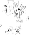
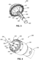
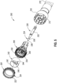
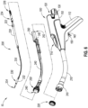
- FIGS. 8 - 14D illustrate embodiments of the invention in FIGS. 8 - 14D , and background and contextual material in FIGS. 1-7 .
- proximal and distal are defined herein relative to a surgeon, or other operator, grasping a surgical instrument having a distal surgical end effector.
- proximal refers to the position of an element arranged closer to the surgeon
- distal refers to the position of an element arranged closer to the surgical end effector of the surgical instrument and further away from the surgeon.
- spatial terms such as “top,” “bottom,” “upper,” “lower,” “vertical,” “horizontal,” or the like are used herein with reference to the drawings, it will be appreciated that such terms are used for exemplary description purposes only and are not intended to be limiting or absolute. In that regard, it will be understood that surgical instruments such as those disclosed herein may be used in a variety of orientations and positions not limited to those shown and described herein.
- anvil (400) is configured to removably couple with shaft assembly (200), adjacent to stapling head assembly (300).
- anvil (400) and stapling head assembly (300) are configured to cooperate to manipulate tissue in three ways, including clamping the tissue, cutting the tissue, and stapling the tissue.
- a rotatable knob (130) at the proximal end of handle assembly (100) is rotatable to provide precise clamping of the tissue between anvil (400) and stapling head assembly (300).
- deck member (320) has a central opening that defines an inner diameter that is just slightly larger than the outer diameter defined by knife member (340). Deck member (320) is thus configured to permit knife member (340) to translate longitudinally through the central opening concurrently with longitudinal translation of staple driver member (350). In particular, knife member (340) is configured to actuate relative to deck member (340) between a proximal retracted position and a distal extended position, where cutting edge (342) is proximal to deck surface (322) in the proximal retracted position and distal to deck surface (322) in the distal extended position.
- handle assembly (100) includes a casing (110) having a lower portion that defines an obliquely oriented pistol grip (112) and an upper portion that supports a user interface feature (114) and releasably receives a battery pack (120), as described in greater detail below.
- Handle assembly (100) further includes several features that are operable to actuate anvil (400) and stapling head assembly (300).
- handle assembly (100) includes a rotatable knob (130), a safety trigger (140), a firing trigger (150), a motor (160), and a motor activation module (180).
- Firing trigger (150) is operable to actuate a switch of motor activation module (180) ( FIG. 1 ) when firing trigger (150) is pivoted proximally to a fired position.
- Motor activation module (180) is in communication with battery pack (120) and motor (160), such that motor activation module (180) is configured to provide activation of motor (160) with electrical power from battery pack (120) in response to firing trigger (150) actuating the switch of motor activation module (180).
- motor (160) will be activated when firing trigger (150) is pivoted. This activation of motor (160) will actuate stapling head assembly (300) via drive bracket (250), as described in greater detail below.
- anvil (400) is secured to trocar (330) by inserting trocar (330) into bore (422) as shown in FIG. 7B .
- Latch members (430) of anvil (400) engage head (334) of trocar (330), thereby providing a secure fit between anvil (400) and trocar (330).
- the operator then rotates knob (130) while holding casing (110) stationary via pistol grip (112). This rotation of knob (130) causes trocar (330) and anvil (400) to retract proximally. As shown in FIG.
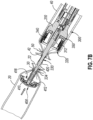
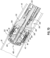
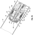
- knife member (340) As knife member (340) translates distally, cutting edge (342) of knife member (340) cuts excess tissue that is positioned within annular recess (418) of anvil (400) and the interior of knife member (340). Additionally, washer (417) positioned within annular recess (418) of anvil (400) is broken by knife member (340) when the knife member (340) completes a full distal range of motion from the position shown in FIG. 7C to the position shown in FIG. 7D . It should be understood that washer (417) may also serve as a cutting board for knife member (340) to assist in cutting of tissue.
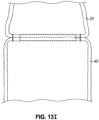
- tissue that was previously clamped by anvil (400) and stapling head assembly (300) may become undesirably associated with (i.e., adhere to, cling to, etc.) surface (322) of stapling head assembly (300) such that after gap distance (d) is increased, the tissue of the newly formed anastomosis adheres to, clings, to, and/or sticks with surface (322) thereby inhibiting a desirable release of tissue. Therefore, in some instances, it may be desirable to incorporate an anastomosis release feature that pushes the tissue of the newly formed anastomosis off surface (322) in order to further promote release of such tissue from surface (322).
- staple driver member (550) is configured to actuate relative to tubular body member (510) in order to drive a plurality of staples through staple openings (524) and against anvil (400).
- staple driver member (550) of the current example includes an annular array of firing ledges (556) extending radially inward from an interior annular surface (555).
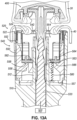
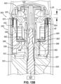
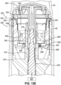
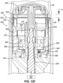
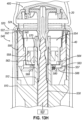
- 13A-13H is configured to actuate knife coupling ring (562) out of engagement with firing ledges (556) and toward floor surface (557) as knife coupling ring (562) and knife (540) are further driven distally by firing ledge (556) after or during the completion of the stapling/severing process in accordance with the description herein.
- cylindraceous knife (540) is substantially similar to cylindraceous knife (340), with differences elaborated herein. Therefore, cylindraceous knife (540) may be actuated distally by stapler driver member (550) in order to sever tissue captured between anvil (400) and deck surface (522) during the firing process.
- stapler driver member (550) rather than coupling with studs (340) that are fixed relative to staple drive remember (350), annular array of openings (546) are dimensioned to receive studs (564) of knife coupling ring (562).
- Knickets (564) of knife coupling ring (562) are dimensioned to fit within a respective opening (546) such that rotation of knife coupling ring (562) drives corresponding rotation of knife (540); while translation of knife coupling ring (562) drives corresponding translation of knife (540).
- knife coupling ring (560) may be integral with knife (540) such that coupling via studs (564) and openings (546) are not necessary.
- other suitable coupling means may be used in order to couple knife coupling ring (560) and knife (540) as would be apparent to one skilled in the art in view of the teachings herein.
- an adhesive may be used to couple ring (560) with knife (540).
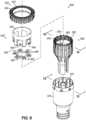
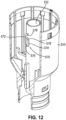
- FIGS. 11 and 12 show various components of knife retracting assembly (560).
- knife retracting assembly (560) is configured to proximally retract cylindraceous knife member (540) within bore (554) defined by staple driver member (552) after the initial firing of stapling head assembly (500).
- Knife retracting assembly (560) includes knife coupling ring (560) having a cam feature (568), a complementary cam assembly (570) associated with inner core member (512), and bias element (580) (see FIG. 13A ) interposed between knife coupling ring (560) and floor surface (557) of stapler driver member (550).
- staple driver member (550) may be actuated a second time such that staple drivers (552) extend distally past deck surface (522) while cutting edge (542) of knife (540) remains proximally below deck surface (522).
- knife coupling ring (560) includes an annular array of ledge engagement bodies (563), each having a respective locating bump (566).
- ledge engagement bodies (563) are configured to rest against firing ledges (556) of staple driver member (550).
- engagement bodies (563) are configured to rest against firing ledges (556) prior to and during the initial firing of staple driver member (550) such that distal actuation of firing ledges (556) drives distal actuation of engagement bodies (563), knife coupling ring (560), and knife (540).
- Locating bumps (566) are dimensioned to fit within recessed pockets (558) such that engagement bodies (563) do not unintentionally disassociate with firing ledges (556).
- complementary cam assembly (570) includes a first body (572) having a first cam surface (576), and a second body (574) having a second cam surface (578).
- First body (572) and second body (574) are fixed relative to inner core member (512).
- First body (572) and second body (574) extend longitudinally along inner core member (512) and together define a guide channel (575).
- Guide channel (575) is positioned along inner core member and dimensioned to slidably receive cam feature (568) (see FIG. 11 ) of knife coupling ring (562).
- First cam surface (576) extends laterally toward second body (574) from the longitudinal path of guide channel (575).
- staple head assembly (500) includes a displacement sensor assembly (502) in communication with motor activation module (180).
- Displacement sensor assembly (502) may be configured to measure the longitudinal location of trocar (530) relative to staple deck member (520) and generate a signal indicative of the longitudinal location of trocar (400). Therefore, the measurement and signal generated by displacement sensor assembly (502) may be indicative of the gap distance (d) formed by deck surface (522) and anvil (400).
- motor activation module (180) may be configured to reactivate motor (160) in response to a signal received by displacement sensor assembly (502) in order to acuate staple drivers (552) distally past deck surface (522) a second time to push tissue off deck surface (522).
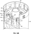
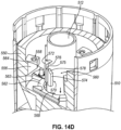
- FIG. 14B shows the position of staple driver member (550) in the fired position as also shown in FIG. 13C .
- FIG. 14B shows cam feature (568) of knife coupling ring (562) located at a distal position of guide channel (575), prior to engaging cam surface (576). Therefore, ledge engagement bodies (563) are still suitably coupled with a respective firing ledge (556).
- bias element (580) actuates knife member (540) toward floor surface (577) of stapler driver member (550) into a retracted position.
- cam feature (568) may engage second cam surface (578) in order to ensure cam feature (568) does not accidentally re-enter channel (575). It should be understood that with knife member (540) in the retracted position, sharp circular cutting edge (542) is retracted proximally within bore (554) such that cutting edge (542) may not be actuated distally past deck surface (522) a second time.
- motor activation module (180) may respond to the signal received from displacement sensor assembly (502) by activating motor (160) to distally acuate staple drivers (552) past deck surface (522) a second time, as shown in FIG. 13H , and then proximally actuate staple drivers (552) toward the pre-fired position. Therefore, displacement sensor assembly (502) may be configured to enable and/or provide for the second actuation of staple drivers (522) in response to anvil (400) releasing tissue after the stapling and severing of tissue in accordance with the description herein.
Landscapes
- Health & Medical Sciences (AREA)
- Life Sciences & Earth Sciences (AREA)
- Surgery (AREA)
- Heart & Thoracic Surgery (AREA)
- Engineering & Computer Science (AREA)
- Biomedical Technology (AREA)
- Nuclear Medicine, Radiotherapy & Molecular Imaging (AREA)
- Medical Informatics (AREA)
- Molecular Biology (AREA)
- Animal Behavior & Ethology (AREA)
- General Health & Medical Sciences (AREA)
- Public Health (AREA)
- Veterinary Medicine (AREA)
- Surgical Instruments (AREA)
Claims (16)
- Chirurgisches Klammerinstrument (10), umfassend:(a) einen Amboss (400), der eine Vielzahl von Klammerformungstaschen (414) definiert;(b) eine Klammerkopfanordnung (500), umfassend:(i) einen Körper (510),(ii) ein Kupplungsglied (530), das konfiguriert ist, um relativ zu dem Körper (510) betätigt zu werden, um dadurch den Amboss (400) relativ zu dem Körper (510) zu betätigen,(iii) eine Deckoberfläche (522), wobei der Amboss (400) und die Deckoberfläche (522) konfiguriert sind, um gemeinsam Gewebe zu greifen,(iv) eine Klammertreiberanordnung (550), die konfiguriert ist, um distal und proximal über einen ersten Ausstoßhub betätigt zu werden, um eine Vielzahl von Klammern (90) gegen die Klammerformungstaschen (414) des Ambosses (400) zu treiben, wobei die Klammertreiberanordnung (550) konfiguriert ist, um distal und proximal über einen zweiten Ausstoßhub betätigt zu werden, und(v) ein Messerglied (540), umfassend eine Schneidkante (542);(c) das Instrument (10) ferner eine Rückzugsanordnung (560) umfasst, die konfiguriert ist, um das Messerglied (540) während des ersten Ausstoßhubs in die zurückgezogene Position zu treiben.
dadurch gekennzeichnet, dass:(vi) ein Teil der Klammertreiberanordnung (550) konfiguriert ist, um während des zweiten Ausstoßhubs distal über die Deckoberfläche (522) hinaus betätigt zu werden,(vii) das Messerglied (540) konfiguriert ist, um während des ersten Ausstoßhubs mit der Klammertreiberanordnung (550) betätigt zu werden, um Gewebe zu durchtrennen, wobei das Messerglied (540) konfiguriert ist, um relativ zu der Klammertreiberanordnung (550) derart in einer zurückgezogenen Position zu bleiben, dass die Schneidkante (542) über den ganzen zweiten Ausstoßhub relativ zu der Deckoberfläche (522) proximal bleibt; und - Chirurgisches Klammerinstrument (10) nach Anspruch 1, wobei die Rückzugsanordnung (560) einen Messerkupplungsring (562), der an dem Messerglied (540) angebracht ist, und eine Nockenanordnung (570), die dem Körper (510) zugeordnet ist, umfasst, wobei die Nockenanordnung (570) konfiguriert ist, um den Messerkupplungsring (562) und das Messerglied (540) während des ersten Ausstoßhubs zu drehen.
- Chirurgisches Klammerinstrument (10) nach Anspruch 2, wobei die Klammertreiberanordnung (550) einen Ausstoßabsatz (556) umfasst, wobei der Messerkupplungsring (562) einen Absatzeingriffskörper (563) umfasst, der konfiguriert ist, um den Ausstoßabsatz (556) während des ersten Ausstoßhubs in Eingriff zu nehmen, um die Schneidkante (542) zu betätigen, um Gewebe zu durchtrennen, wobei die Nockenanordnung (570) konfiguriert ist, um den Absatzeingriffskörper (563) während des ersten Ausstoßhubs von dem Ausstoßabsatz (556) weg zu drehen.
- Chirurgisches Klammerinstrument (10) nach Anspruch 2 oder 3, wobei der Messerkupplungsring (562) einen Vorsprung (568) umfasst, der bemessen ist, um innerhalb eines Führungspfads (575), der durch die Nockenanordnung (570) definiert ist, zu passen.
- Chirurgisches Instrument (10) nach einem der Ansprüche 2 bis 4, wobei der Körper (510) ein röhrenförmiges Außenglied und ein Innenkernglied (512) umfasst, wobei die Nockenanordnung (570) dem Innenkernglied (512) zugeordnet ist.
- Chirurgisches Instrument (10) nach Anspruch 5, wobei der Messerkupplungsring (562) eine zentrale Öffnung (565) definiert, wobei das Innenkernglied (512) innerhalb der zentralen Öffnung (565) des Messerkupplungsrings (562) eingerichtet ist.
- Chirurgisches Instrument (10) nach einem der vorstehenden Ansprüche, wobei das Messerglied (540) ein zylindrisches Messer umfasst.
- Chirurgisches Instrument (10) nach einem der vorstehenden Ansprüche, ferner umfassend einen Motor (160), der konfiguriert ist, um die Klammertreiberanordnung (550) über den ersten Hub und den zweiten Hub anzutreiben.
- Chirurgisches Instrument (10) nach einem der vorstehenden Ansprüche, ferner umfassend einen Verschiebungssensor (502), der konfiguriert ist, um die Längsposition des Kupplungsglieds (530) relativ zu dem Körper (510) zu messen.
- Chirurgisches Instrument (10) nach Anspruch 8, ferner umfassend einen Verschiebungssensor (502), der konfiguriert ist, um die Längsposition des Kupplungsglieds (530) relativ zu dem Körper (510) zu messen, und wobei der Motor (160) konfiguriert ist, um den zweiten Hub basierend auf einer Messung von dem Verschiebungssensor (502) einzuleiten.
- Chirurgisches Instrument (10) nach einem der vorstehenden Ansprüche, wobei das Messerglied (540) mittels eines Vorspannelements (580) zu der zurückgezogenen Position hin vorgespannt ist.
- Chirurgisches Instrument (10) nach Anspruch 11, wobei das Vorspannelement (580) eine Feder umfasst.
- Chirurgisches Instrument (10) nach Anspruch 12, wobei die Feder (580) zwischen einer Bodenoberfläche (557) der Klammertreiberanordnung (550) und dem Messerglied (540) eingeschoben ist.
- Chirurgisches Instrument (10) nach einem der vorstehenden Ansprüche, ferner umfassend eine Griffanordnung (100).
- Chirurgisches Instrument (10) nach Anspruch 14, ferner umfassend einen Drehknopf (130), der der Griffanordnung (100) zugeordnet ist, wobei der Drehknopf (130) konfiguriert ist, um eine Betätigung des Kupplungsglieds (530) relativ zu dem Körper (510) anzutreiben.
- Chirurgisches Klammerinstrument (10) nach Anspruch 1, wobei:die Schneidkante (542) konfiguriert ist, um sich während des ersten Ausstoßhubs distal über die Deckoberfläche (522) hinaus zu erstrecken; unddie Rückzugsanordnung (560) umfasst:(i) ein Vorspannelement (580),(ii) eine erste Nockenoberfläche (576), die dem Körper (510) zugeordnet ist, und(iii) eine zweite Nockenoberfläche (578), die dem Messerglied (540) zugeordnet ist, wobei die erste Nockenoberfläche (576) und die zweite Nockenoberfläche (578) konfiguriert sind, um das Messerglied (540) während des ersten Ausstoßhubs derart aus einem betriebsfähigen Eingriff mit der Klammertreiberanordnung (550) zu treiben, dass das Vorspannelement (580) das Messerglied (540) in die zurückgezogene Position betätigt.
Applications Claiming Priority (2)
| Application Number | Priority Date | Filing Date | Title |
|---|---|---|---|
| US17/489,871 US12064116B2 (en) | 2021-09-30 | 2021-09-30 | Circular surgical stapler with anastomosis release feature |
| PCT/IB2022/059171 WO2023052989A1 (en) | 2021-09-30 | 2022-09-27 | Circular surgical stapler with anastomosis release feature |
Publications (3)
| Publication Number | Publication Date |
|---|---|
| EP4236829A1 EP4236829A1 (de) | 2023-09-06 |
| EP4236829C0 EP4236829C0 (de) | 2024-07-10 |
| EP4236829B1 true EP4236829B1 (de) | 2024-07-10 |
Family
ID=83691128
Family Applications (1)
| Application Number | Title | Priority Date | Filing Date |
|---|---|---|---|
| EP22789685.9A Active EP4236829B1 (de) | 2021-09-30 | 2022-09-27 | Ringförmiges chirurgisches klammergerät mit anastomosefreisetzungsfunktion |
Country Status (3)
| Country | Link |
|---|---|
| US (1) | US12064116B2 (de) |
| EP (1) | EP4236829B1 (de) |
| WO (1) | WO2023052989A1 (de) |
Families Citing this family (6)
| Publication number | Priority date | Publication date | Assignee | Title |
|---|---|---|---|---|
| US11911039B2 (en) | 2021-08-13 | 2024-02-27 | Cilag Gmbh International | Circular surgical stapler having staples with expandable crowns |
| US11998209B2 (en) | 2021-08-13 | 2024-06-04 | Cilag Gmbh International | Staple forming features for circular surgical stapler |
| US12256934B2 (en) | 2021-08-13 | 2025-03-25 | Cilag Gmbh International | Methods of forming an anastomosis between organs with an expandable pattern |
| US11944310B2 (en) | 2021-08-13 | 2024-04-02 | Cilag Gmbh International | Non-circular end effector features for surgical stapler |
| US12201301B2 (en) * | 2021-08-13 | 2025-01-21 | Cilag Gmbh International | Circular surgical stapler end effector having staple line alignment feature |
| US12064116B2 (en) * | 2021-09-30 | 2024-08-20 | Cilag Gmbh International | Circular surgical stapler with anastomosis release feature |
Family Cites Families (48)
| Publication number | Priority date | Publication date | Assignee | Title |
|---|---|---|---|---|
| US4198982A (en) * | 1978-03-31 | 1980-04-22 | Memorial Hospital For Cancer And Allied Diseases | Surgical stapling instrument and method |
| US4556058A (en) * | 1983-08-17 | 1985-12-03 | United States Surgical Corporation | Apparatus for ligation and division with fixed jaws |
| US4903697A (en) * | 1986-03-27 | 1990-02-27 | Semion Resnick | Cartridge assembly for a surgical stapling instrument |
| US5222963A (en) * | 1991-01-17 | 1993-06-29 | Ethicon, Inc. | Pull-through circular anastomosic intraluminal stapler with absorbable fastener means |
| US5333773A (en) | 1991-08-23 | 1994-08-02 | Ethicon, Inc. | Sealing means for endoscopic surgical anastomosis stapling instrument |
| GR920100358A (el) | 1991-08-23 | 1993-06-07 | Ethicon Inc | Οργανο συρραφής χειρουργικής αναστομώσεως. |
| US5350104A (en) | 1991-08-23 | 1994-09-27 | Ethicon, Inc. | Sealing means for endoscopic surgical anastomosis stapling instrument |
| US5271543A (en) | 1992-02-07 | 1993-12-21 | Ethicon, Inc. | Surgical anastomosis stapling instrument with flexible support shaft and anvil adjusting mechanism |
| US7207472B2 (en) | 2003-12-30 | 2007-04-24 | Ethicon Endo-Surgery, Inc. | Cartridge with locking knife for a curved cutter stapler |
| US8931682B2 (en) * | 2007-06-04 | 2015-01-13 | Ethicon Endo-Surgery, Inc. | Robotically-controlled shaft based rotary drive systems for surgical instruments |
| US8267301B2 (en) * | 2009-08-19 | 2012-09-18 | Tyco Healthcare Group Lp | Surgical stapler |
| US8439246B1 (en) * | 2010-07-20 | 2013-05-14 | Cardica, Inc. | Surgical stapler with cartridge-adjustable clamp gap |
| US9877720B2 (en) * | 2010-09-24 | 2018-01-30 | Ethicon Llc | Control features for articulating surgical device |
| US8746532B2 (en) | 2011-05-19 | 2014-06-10 | Ethicon Endo-Surgery, Inc. | Anvil and cartridge alignment configuration for a circular stapler |
| US9168042B2 (en) * | 2012-01-12 | 2015-10-27 | Covidien Lp | Circular stapling instruments |
| US9186141B2 (en) * | 2012-04-12 | 2015-11-17 | Covidien Lp | Circular anastomosis stapling apparatus utilizing a two stroke firing sequence |
| US9572572B2 (en) * | 2012-11-09 | 2017-02-21 | Covidien Lp | Circular stapler mechanical lockout |
| CN103156660B (zh) * | 2012-12-26 | 2015-05-06 | 苏州天臣国际医疗科技有限公司 | 圆管型吻合器 |
| CN104902826B (zh) * | 2012-12-31 | 2017-10-27 | 直观外科手术操作公司 | 具有增大的刀间隙的外科手术钉仓 |
| US9351724B2 (en) * | 2013-01-11 | 2016-05-31 | Covidien Lp | Circular stapling instrument |
| US9504470B2 (en) * | 2013-02-25 | 2016-11-29 | Covidien Lp | Circular stapling device with buttress |
| US9814463B2 (en) * | 2013-03-13 | 2017-11-14 | Covidien Lp | Surgical stapling apparatus |
| US9750503B2 (en) * | 2013-07-11 | 2017-09-05 | Covidien Lp | Methods and devices for performing a surgical anastomosis |
| US10709452B2 (en) | 2013-09-23 | 2020-07-14 | Ethicon Llc | Methods and systems for performing circular stapling |
| US20150083772A1 (en) | 2013-09-23 | 2015-03-26 | Ethicon Endo-Surgery, Inc. | Surgical stapler with rotary cam drive and return |
| US9936949B2 (en) | 2013-09-23 | 2018-04-10 | Ethicon Llc | Surgical stapling instrument with drive assembly having toggle features |
| US9907552B2 (en) | 2013-09-23 | 2018-03-06 | Ethicon Llc | Control features for motorized surgical stapling instrument |
| US9713469B2 (en) | 2013-09-23 | 2017-07-25 | Ethicon Llc | Surgical stapler with rotary cam drive |
| US20180132849A1 (en) | 2016-11-14 | 2018-05-17 | Ethicon Endo-Surgery, Llc | Staple forming pocket configurations for circular surgical stapler anvil |
| US9730694B2 (en) * | 2014-07-01 | 2017-08-15 | Covidien Lp | Loading unit including shipping assembly |
| US9757133B2 (en) * | 2014-07-09 | 2017-09-12 | Covidien Lp | Methods and devices for performing a surgical anastomosis |
| WO2018071497A1 (en) * | 2016-10-11 | 2018-04-19 | Intuitive Surgical Operations, Inc. | Stapler cartridge with an integral knife |
| US10499922B2 (en) * | 2016-11-04 | 2019-12-10 | Covidien Lp | Stapling device with self-releasing knife carrier pusher |
| US10542993B2 (en) * | 2017-02-24 | 2020-01-28 | Covidien Lp | Anvil assembly of circular stapling device including alignment splines |
| CN116138828B (zh) | 2017-02-27 | 2025-12-05 | 苏州法兰克曼医疗器械有限公司 | 一种外科切割吻合器 |
| US10687819B2 (en) | 2018-02-06 | 2020-06-23 | Ethicon Llc | Clamping mechanism for linear surgical stapler |
| US10667818B2 (en) | 2018-02-06 | 2020-06-02 | Ethicon Llc | Lockout assembly for linear surgical stapler |
| US10631866B2 (en) | 2018-02-06 | 2020-04-28 | Ethicon Llc | Release mechanism for linear surgical stapler |
| US10874398B2 (en) | 2018-02-06 | 2020-12-29 | Ethicon Llc | Firing lever assembly for linear surgical stapler |
| US10932781B2 (en) | 2018-02-06 | 2021-03-02 | Ethicon Llc | Features to align and close linear surgical stapler |
| US11278285B2 (en) | 2018-08-13 | 2022-03-22 | Cilag GbmH International | Clamping assembly for linear surgical stapler |
| US10898187B2 (en) | 2018-08-13 | 2021-01-26 | Ethicon Llc | Firing system for linear surgical stapler |
| US11033266B2 (en) | 2018-08-13 | 2021-06-15 | Cilag Gmbh International | Decoupling mechanism for linear surgical stapler |
| US10905419B2 (en) | 2018-10-11 | 2021-02-02 | Ethicon Llc | Closure assembly for linear surgical stapler |
| US11045193B2 (en) | 2018-10-11 | 2021-06-29 | Cilag Gmbh International | Anvil assembly for linear surgical stapler |
| US11331782B2 (en) * | 2019-03-01 | 2022-05-17 | Covidien Lp | Reload assembly for a circular stapling device |
| US11229433B2 (en) | 2019-08-09 | 2022-01-25 | Cilag Gmbh International | Linear surgical stapler |
| US12064116B2 (en) * | 2021-09-30 | 2024-08-20 | Cilag Gmbh International | Circular surgical stapler with anastomosis release feature |
-
2021
- 2021-09-30 US US17/489,871 patent/US12064116B2/en active Active
-
2022
- 2022-09-27 EP EP22789685.9A patent/EP4236829B1/de active Active
- 2022-09-27 WO PCT/IB2022/059171 patent/WO2023052989A1/en not_active Ceased
Also Published As
| Publication number | Publication date |
|---|---|
| EP4236829C0 (de) | 2024-07-10 |
| EP4236829A1 (de) | 2023-09-06 |
| US20230102965A1 (en) | 2023-03-30 |
| WO2023052989A1 (en) | 2023-04-06 |
| US12064116B2 (en) | 2024-08-20 |
Similar Documents
| Publication | Publication Date | Title |
|---|---|---|
| EP4236829B1 (de) | Ringförmiges chirurgisches klammergerät mit anastomosefreisetzungsfunktion | |
| US11744579B2 (en) | Surgical stapler with anvil seating detection | |
| EP3639765B1 (de) | Rückstellbares chirurgisches klammergerät | |
| US11013513B2 (en) | Motor driven rotary input circular stapler with modular end effector | |
| US10492788B2 (en) | Powered surgical circular stapler with removable cartridge and variable staple height | |
| CN108135603B (zh) | 具有轴释放、动力击发和动力关节运动的外科缝合器械 | |
| EP3117778A1 (de) | Verriegelungsvorrichtung für ein bewegliches schneidelement eines chirurgisches instruments | |
| EP3795095B1 (de) | Ambossrückhalte- und -freigabefunktionen für angetriebene kreisförmige chirurgische klammergeräte | |
| US12201301B2 (en) | Circular surgical stapler end effector having staple line alignment feature | |
| US12035916B2 (en) | Surgical stapler with reversible polarity | |
| EP3420973B1 (de) | Angetriebenes kreisförmiges klammergerät mit kolbenantriebselement zur bereitstellung von unabhängigem klammern und schneiden von gewebe | |
| US12433595B2 (en) | Staple driver and guide assembly for circular surgical stapler | |
| EP4106640B1 (de) | Messer für ein kreisförmiges chirurgisches klammergerät | |
| EP3563778A2 (de) | Chirurgisches klammergerät mit umkehrbarer polarität |
Legal Events
| Date | Code | Title | Description |
|---|---|---|---|
| STAA | Information on the status of an ep patent application or granted ep patent |
Free format text: STATUS: UNKNOWN |
|
| STAA | Information on the status of an ep patent application or granted ep patent |
Free format text: STATUS: THE INTERNATIONAL PUBLICATION HAS BEEN MADE |
|
| PUAI | Public reference made under article 153(3) epc to a published international application that has entered the european phase |
Free format text: ORIGINAL CODE: 0009012 |
|
| STAA | Information on the status of an ep patent application or granted ep patent |
Free format text: STATUS: REQUEST FOR EXAMINATION WAS MADE |
|
| 17P | Request for examination filed |
Effective date: 20230530 |
|
| AK | Designated contracting states |
Kind code of ref document: A1 Designated state(s): AL AT BE BG CH CY CZ DE DK EE ES FI FR GB GR HR HU IE IS IT LI LT LU LV MC MK MT NL NO PL PT RO RS SE SI SK SM TR |
|
| GRAP | Despatch of communication of intention to grant a patent |
Free format text: ORIGINAL CODE: EPIDOSNIGR1 |
|
| STAA | Information on the status of an ep patent application or granted ep patent |
Free format text: STATUS: GRANT OF PATENT IS INTENDED |
|
| DAV | Request for validation of the european patent (deleted) | ||
| DAX | Request for extension of the european patent (deleted) | ||
| INTG | Intention to grant announced |
Effective date: 20240402 |
|
| GRAS | Grant fee paid |
Free format text: ORIGINAL CODE: EPIDOSNIGR3 |
|
| GRAA | (expected) grant |
Free format text: ORIGINAL CODE: 0009210 |
|
| STAA | Information on the status of an ep patent application or granted ep patent |
Free format text: STATUS: THE PATENT HAS BEEN GRANTED |
|
| AK | Designated contracting states |
Kind code of ref document: B1 Designated state(s): AL AT BE BG CH CY CZ DE DK EE ES FI FR GB GR HR HU IE IS IT LI LT LU LV MC MK MT NL NO PL PT RO RS SE SI SK SM TR |
|
| REG | Reference to a national code |
Ref country code: CH Ref legal event code: EP |
|
| REG | Reference to a national code |
Ref country code: DE Ref legal event code: R096 Ref document number: 602022004511 Country of ref document: DE |
|
| U01 | Request for unitary effect filed |
Effective date: 20240726 |
|
| U07 | Unitary effect registered |
Designated state(s): AT BE BG DE DK EE FI FR IT LT LU LV MT NL PT RO SE SI Effective date: 20240902 |
|
| U20 | Renewal fee for the european patent with unitary effect paid |
Year of fee payment: 3 Effective date: 20240902 |
|
| PG25 | Lapsed in a contracting state [announced via postgrant information from national office to epo] |
Ref country code: NO Free format text: LAPSE BECAUSE OF FAILURE TO SUBMIT A TRANSLATION OF THE DESCRIPTION OR TO PAY THE FEE WITHIN THE PRESCRIBED TIME-LIMIT Effective date: 20241010 |
|
| PG25 | Lapsed in a contracting state [announced via postgrant information from national office to epo] |
Ref country code: GR Free format text: LAPSE BECAUSE OF FAILURE TO SUBMIT A TRANSLATION OF THE DESCRIPTION OR TO PAY THE FEE WITHIN THE PRESCRIBED TIME-LIMIT Effective date: 20241011 Ref country code: PL Free format text: LAPSE BECAUSE OF FAILURE TO SUBMIT A TRANSLATION OF THE DESCRIPTION OR TO PAY THE FEE WITHIN THE PRESCRIBED TIME-LIMIT Effective date: 20240710 |
|
| PG25 | Lapsed in a contracting state [announced via postgrant information from national office to epo] |
Ref country code: IS Free format text: LAPSE BECAUSE OF FAILURE TO SUBMIT A TRANSLATION OF THE DESCRIPTION OR TO PAY THE FEE WITHIN THE PRESCRIBED TIME-LIMIT Effective date: 20241110 |
|
| PG25 | Lapsed in a contracting state [announced via postgrant information from national office to epo] |
Ref country code: HR Free format text: LAPSE BECAUSE OF FAILURE TO SUBMIT A TRANSLATION OF THE DESCRIPTION OR TO PAY THE FEE WITHIN THE PRESCRIBED TIME-LIMIT Effective date: 20240710 |
|
| PG25 | Lapsed in a contracting state [announced via postgrant information from national office to epo] |
Ref country code: ES Free format text: LAPSE BECAUSE OF FAILURE TO SUBMIT A TRANSLATION OF THE DESCRIPTION OR TO PAY THE FEE WITHIN THE PRESCRIBED TIME-LIMIT Effective date: 20240710 Ref country code: RS Free format text: LAPSE BECAUSE OF FAILURE TO SUBMIT A TRANSLATION OF THE DESCRIPTION OR TO PAY THE FEE WITHIN THE PRESCRIBED TIME-LIMIT Effective date: 20241010 |
|
| PG25 | Lapsed in a contracting state [announced via postgrant information from national office to epo] |
Ref country code: RS Free format text: LAPSE BECAUSE OF FAILURE TO SUBMIT A TRANSLATION OF THE DESCRIPTION OR TO PAY THE FEE WITHIN THE PRESCRIBED TIME-LIMIT Effective date: 20241010 Ref country code: PL Free format text: LAPSE BECAUSE OF FAILURE TO SUBMIT A TRANSLATION OF THE DESCRIPTION OR TO PAY THE FEE WITHIN THE PRESCRIBED TIME-LIMIT Effective date: 20240710 Ref country code: NO Free format text: LAPSE BECAUSE OF FAILURE TO SUBMIT A TRANSLATION OF THE DESCRIPTION OR TO PAY THE FEE WITHIN THE PRESCRIBED TIME-LIMIT Effective date: 20241010 Ref country code: IS Free format text: LAPSE BECAUSE OF FAILURE TO SUBMIT A TRANSLATION OF THE DESCRIPTION OR TO PAY THE FEE WITHIN THE PRESCRIBED TIME-LIMIT Effective date: 20241110 Ref country code: HR Free format text: LAPSE BECAUSE OF FAILURE TO SUBMIT A TRANSLATION OF THE DESCRIPTION OR TO PAY THE FEE WITHIN THE PRESCRIBED TIME-LIMIT Effective date: 20240710 Ref country code: GR Free format text: LAPSE BECAUSE OF FAILURE TO SUBMIT A TRANSLATION OF THE DESCRIPTION OR TO PAY THE FEE WITHIN THE PRESCRIBED TIME-LIMIT Effective date: 20241011 Ref country code: ES Free format text: LAPSE BECAUSE OF FAILURE TO SUBMIT A TRANSLATION OF THE DESCRIPTION OR TO PAY THE FEE WITHIN THE PRESCRIBED TIME-LIMIT Effective date: 20240710 |
|
| PG25 | Lapsed in a contracting state [announced via postgrant information from national office to epo] |
Ref country code: SM Free format text: LAPSE BECAUSE OF FAILURE TO SUBMIT A TRANSLATION OF THE DESCRIPTION OR TO PAY THE FEE WITHIN THE PRESCRIBED TIME-LIMIT Effective date: 20240710 |
|
| PG25 | Lapsed in a contracting state [announced via postgrant information from national office to epo] |
Ref country code: MC Free format text: LAPSE BECAUSE OF FAILURE TO SUBMIT A TRANSLATION OF THE DESCRIPTION OR TO PAY THE FEE WITHIN THE PRESCRIBED TIME-LIMIT Effective date: 20240710 |
|
| PG25 | Lapsed in a contracting state [announced via postgrant information from national office to epo] |
Ref country code: CZ Free format text: LAPSE BECAUSE OF FAILURE TO SUBMIT A TRANSLATION OF THE DESCRIPTION OR TO PAY THE FEE WITHIN THE PRESCRIBED TIME-LIMIT Effective date: 20240710 |
|
| PG25 | Lapsed in a contracting state [announced via postgrant information from national office to epo] |
Ref country code: SK Free format text: LAPSE BECAUSE OF FAILURE TO SUBMIT A TRANSLATION OF THE DESCRIPTION OR TO PAY THE FEE WITHIN THE PRESCRIBED TIME-LIMIT Effective date: 20240710 |
|
| PLBE | No opposition filed within time limit |
Free format text: ORIGINAL CODE: 0009261 |
|
| STAA | Information on the status of an ep patent application or granted ep patent |
Free format text: STATUS: NO OPPOSITION FILED WITHIN TIME LIMIT |
|
| 26N | No opposition filed |
Effective date: 20250411 |
|
| PG25 | Lapsed in a contracting state [announced via postgrant information from national office to epo] |
Ref country code: IE Free format text: LAPSE BECAUSE OF NON-PAYMENT OF DUE FEES Effective date: 20240927 |
|
| U20 | Renewal fee for the european patent with unitary effect paid |
Year of fee payment: 4 Effective date: 20250807 |
|
| PG25 | Lapsed in a contracting state [announced via postgrant information from national office to epo] |
Ref country code: CY Free format text: LAPSE BECAUSE OF FAILURE TO SUBMIT A TRANSLATION OF THE DESCRIPTION OR TO PAY THE FEE WITHIN THE PRESCRIBED TIME-LIMIT; INVALID AB INITIO Effective date: 20220927 |
|
| PG25 | Lapsed in a contracting state [announced via postgrant information from national office to epo] |
Ref country code: HU Free format text: LAPSE BECAUSE OF FAILURE TO SUBMIT A TRANSLATION OF THE DESCRIPTION OR TO PAY THE FEE WITHIN THE PRESCRIBED TIME-LIMIT; INVALID AB INITIO Effective date: 20220927 |