EP4237157B1 - Séparateur - Google Patents
Séparateur Download PDFInfo
- Publication number
- EP4237157B1 EP4237157B1 EP21802259.8A EP21802259A EP4237157B1 EP 4237157 B1 EP4237157 B1 EP 4237157B1 EP 21802259 A EP21802259 A EP 21802259A EP 4237157 B1 EP4237157 B1 EP 4237157B1
- Authority
- EP
- European Patent Office
- Prior art keywords
- discharge
- opening
- intermediate phase
- phase
- discharge device
- Prior art date
- Legal status (The legal status is an assumption and is not a legal conclusion. Google has not performed a legal analysis and makes no representation as to the accuracy of the status listed.)
- Active
Links
Images


Classifications
-
- B—PERFORMING OPERATIONS; TRANSPORTING
- B04—CENTRIFUGAL APPARATUS OR MACHINES FOR CARRYING-OUT PHYSICAL OR CHEMICAL PROCESSES
- B04B—CENTRIFUGES
- B04B1/00—Centrifuges with rotary bowls provided with solid jackets for separating predominantly liquid mixtures with or without solid particles
- B04B1/10—Centrifuges with rotary bowls provided with solid jackets for separating predominantly liquid mixtures with or without solid particles with discharging outlets in the plane of the maximum diameter of the bowl
- B04B1/14—Centrifuges with rotary bowls provided with solid jackets for separating predominantly liquid mixtures with or without solid particles with discharging outlets in the plane of the maximum diameter of the bowl with periodical discharge
-
- B—PERFORMING OPERATIONS; TRANSPORTING
- B04—CENTRIFUGAL APPARATUS OR MACHINES FOR CARRYING-OUT PHYSICAL OR CHEMICAL PROCESSES
- B04B—CENTRIFUGES
- B04B11/00—Feeding, charging, or discharging bowls
- B04B11/04—Periodical feeding or discharging; Control arrangements therefor
Definitions
- the invention relates to a self-emptying separator for the centrifugal separation of a suspension S into at least one light liquid phase LP, one heavy solid phase SP and one medium-heavy intermediate phase IP, which has a centrifugal drum rotatable about a rotational axis D according to the preamble of claim 1 and a method according to claim 17.
- discontinuous self-draining separators In addition to one or more continuous outlets for one or more liquid phases, generic discontinuous self-draining separators have a discharge system with a piston valve that can be moved alternately into an open and a closed position by a fluid, particularly with liquid as the fluid.
- the piston valve opens (open position) and closes (closed position) one or more solids discharge openings in the drum wall. In the open position, a solid phase is ejected from the centrifugal drum and thus removed from the drum. In the closed position, the solids discharge openings are closed, preventing this from happening.
- an incoming suspension is separated in the drum into a lighter or less dense liquid phase, a medium-heavy or medium-dense intermediate phase that is usually still flowable, and a heavier (possibly also still flowable) or denser solid phase.
- the light phase is the least dense phase
- the medium-heavy phase is a phase with a relatively higher density
- the heavy phase is one with an even higher density.
- the mechanically acting opening and closing means of the first discharge device is a piston slide arranged in or on the outside of the centrifugal drum, in particular a hydraulically controllable piston slide, which can be moved into different positions in order to open the one or more solids discharge openings in an open position or to close them in a closed position.
- the mechanically acting opening and closing means of the first discharge device has at least one or more electrically or fluidically controllable valves, in particular piston valves, which are assigned to the respective solids discharge opening(s) in order to open them or to close them in a closed position.
- the mechanically acting opening and closing means of the second discharge device is a piston slide which is arranged on the outside of the centrifugal drum and is in particular hydraulically controllable and which can be moved into different positions in order to open the one or more discharge openings for the intermediate phase IP in an open position or to close them in a closed position, or it can be provided that the mechanically acting opening and closing means of the second discharge device has at least one or more electrically or fluidically controllable valves, in particular piston valves, which are assigned to the respective discharge opening(s) for the intermediate phase IP in order to open them or to close them in a closed position.
- the mechanically acting opening and closing means of the first discharge device is a piston slide arranged in the centrifugal drum, in particular a hydraulically controllable piston valve
- the mechanically acting opening and closing means of the second discharge device is at least one controllable piston valve which is assigned to the respective discharge openings for the intermediate phase IP in order to open them or to close them in a closed position.
- the mechanically acting opening and closing means of the first discharge device has controllable piston valves which are assigned to the respective solids discharge openings in order to open them or to close them in a closed position
- the mechanically acting opening and closing means of the second discharge device has controllable piston valves which are assigned to the respective discharge openings for the intermediate phase IP in order to open them or to close them in a closed position.
- radius R3 is smaller than radius R2, where the solid discharge openings are located, but larger than radius R1, where the liquid phase LP is discharged. This advantageously results in a defined discharge of each phase, largely eliminating mixing with the other phases.
- a paring disc can be assigned to the liquid discharge.
- the liquid discharge can also be implemented in other ways.
- the discharged solid phase SP is expelled through the at least one solid discharge opening into a first annular space serving as a solids catcher.
- the first annular space is arranged in a hood-like housing and has a nozzle arranged radially on the first annular space for connecting a hose or a line for further discharge of the solid phase SP.
- the discharged intermediate phase IP passes through the at least one discharge opening into a further annular space arranged in the hood-like housing and having a nozzle arranged radially on the further annular space for connecting a hose or a line for further discharge of the intermediate phase IP.
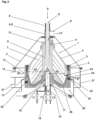
- the light liquid phase LP which flows radially inward from the disc pack 7, flows into a paring disc chamber 10, which rotates with the centrifugal drum 1.
- a paring disc 11 is arranged in the paring disc chamber 10. This paring disc 11 is non-rotatable in the paring disc chamber 10, i.e., is arranged stationary.
- the paring disc 11 - also referred to as a gripper - which operates as a centripetal pump
- the liquid phase LP is diverted from the centrifugal field forming in the operating centrifugal drum 1 on a radius R1 and guided or directed out of the centrifugal drum 1 via the liquid discharge 9, the annular space 9', and the nozzle 9".
- the discharge of the liquid phase LP thus takes place continuously.
- a fluidically and/or electrically - here fluidically - controllable and mechanically acting opening and closing means is provided, which is designed here as an - inner - piston slide 12 arranged in the centrifugal drum 1.
- the inner piston valve 12 is provided for opening and closing at least one solids discharge opening 13.
- several of the solids discharge openings 13 can be circumferentially distributed in the region of the largest diameter—on a radius R2—of the centrifugal drum 1.
- the discharged solid phase SP passes into a first solids trap-like annular space 14, which is arranged in the housing 2 and can have a nozzle 14' arranged radially on the first annular space 14 for connecting a hose or a line for further discharge of the solid phase SP.
- a first discharge device 15 For discharging the solid phase SP, a first discharge device 15 is provided, which comprises a mechanically acting opening and closing means that can be fluidically actuated by actuators to carry out opening and closing movements.
- the first discharge device 15 can comprise an injection chamber 16 for opening fluid and an injection chamber 17 for closing fluid, to which a fluid, in particular water, for activating the opening and closing movements of the inner piston slide 12 can be supplied via an opening fluid supply 18 and a closing fluid supply 19, in which a first opening fluid valve V1 and a first closing fluid valve V2 are arranged.
- the closing process of the solids discharge openings 13, i.e., in this case, a lifting of the inner piston slide 12, can be achieved by closing fluid, which is injected into a chamber below the inner piston slide 12.
- the closing fluid is metered via the closing fluid valve V2.
- the chamber is connected to piston valves 20, which are arranged in the wall of the centrifugal drum 1 in such a way that they can be closed by the centrifugal force prevailing in the centrifugal drum 1 when in operation.
- the opening process of the solids discharge openings 13, i.e., the lowering of the inner piston slide 12, is achieved by opening fluid, which opens the piston valves 20, which in turn allows the closing fluid below the inner piston slide 12 to escape from the chamber.
- opening fluid which opens the piston valves 20, which in turn allows the closing fluid below the inner piston slide 12 to escape from the chamber.
- a small amount of opening fluid is briefly fed through a supply line via an opening fluid injection chamber 16 into connecting lines in the drum base 3.
- the opening fluid ensures the buildup of all-round fluid pressure, which moves a closing piston against the centrifugal force in a radial direction toward the rotational axis D, thus opening the piston valve 20 of the centrifugal drum 1.
- the opening fluid is dosed via the opening fluid valve V1.
- the closing fluid escapes into a second annular space 21, which is arranged in the housing 2 and can have a nozzle 21' arranged radially on the second annular space 21 for connecting a hose or a line for further discharge of the fluid.
- the outer, second piston valve 22 is arranged below the centrifugal drum 1 on its outer side.
- the piston valve 22 is intended to close or open the discharge openings 25 so that the intermediate phase IP can be discharged from the discharge openings 25.
- the piston valve 22 is movable in the axial direction.
- the piston valve 22 is movably guided in a support ring 22'.
- the support ring 22' has lines 27, 28, and possibly an overflow bore 32, which can be supplied with opening or closing fluid as required, which will be described in more detail below.
- the intermediate phase IP can be discharged through nozzle-like pipes 23, which are mounted in bores in the inner piston valve 12 distributed around the circumference and whose length is adjusted so that it extends into the layer of the intermediate phase IP that forms during rotation of the centrifugal drum 1, which is characterized here by a radius R3.
- the intermediate phase IP reaches at least one, preferably several, discharge openings 25 distributed around the circumference of the centrifugal drum 1, which can be closed or opened by the outer piston valve 22.
- the radius R3 is smaller than a larger radius R2 on which the inlets of the heavy solids discharge openings 13 are arranged, but larger than the radius R1 on which the light liquid phase LP is discharged by the paring disc 11.
- a discontinuously operating second discharge device 26 is provided, which comprises the mechanical opening and closing means, which can be fluidically actuated by actuators to carry out opening and closing movements.
- piston valves 31 are provided, each of which serves or is used for a controlled discharge of the fluid used to carry out the opening and closing movements of the outer piston slide 22.
- the closing fluid escapes through the piston valves 31 into a fourth annular space 34, which is arranged in the housing 2 and can have a nozzle 34' arranged radially on the fourth annular space 34 for connecting a hose or a line for further discharge of the fluid.
- the actuation of the inner piston slide 12 and the actuation of the outer piston slide 22 can be controlled independently of each other by a control unit (not shown here).
- the control unit can also be a central control unit for controlling the separator, which, in addition to controlling the two Piston slide 12, 22 is also intended for other control and/or regulation tasks of the centrifuge.
- FIG. 2 Another separator is shown.
- the basic structure largely corresponds to that of the separator of the Fig. 1 .
- the following mainly describes deviations and/or additions to the design variant of the Fig. 1 described.
- a first opening fluid valve V5 is provided here to supply opening fluid and a first closing fluid valve V6 is provided to supply closing fluid.
- the discharge of the intermediate phase IP takes place according to the design variant of the Fig. 2 initially again through nozzle-like pipes 23, which are mounted in initially radially extending bores in the inner piston slide 12, which merge into axial bores 24 in the drum base 3 or with which they correspond, and whose length is adapted so that they reach into the layer of the intermediate phase IP that forms upon rotation of the centrifugal drum 1, here characterized by a radius R3.
- the radius R3 is smaller than the radius R2, on which the solids discharge openings 13 are arranged, but larger than the radius R1, on which the liquid phase LP is discharged by the paring disc 11.
- the actuation of the inner piston slide 12 and the actuation of the controllable piston valves 35 can be controlled independently of each other by a control unit (not shown here).
- the control unit can also be a central centrifuge control unit, which, in addition to controlling the inner piston slide and the piston valves 35, is also intended for other control and regulation tasks of the centrifuge.
- the intermediate phase IP is controlled by at least one, preferably several piston valves 35, which are distributed around the circumference of the centrifugal drum 1 - as already described for the embodiment according to Fig. 2 described - derived from the centrifugal drum 1.
- the piston valves 35 here are the opening and closing means of the discontinuously operating, second discharge device 26, which serves to discharge the intermediate phase IP from the centrifugal drum 1.
- the solid phase SP is also Fig. 3 by at least one, preferably several piston valves 38, which are distributed around the circumference of the centrifugal drum 1, from the centrifugal drum 1.
- the piston valves 38 are here the opening and closing means of the discontinuously operating, first discharge device 15, which serves to discharge the solid phase SP from the centrifugal drum 1.
- both the solid phase SP and the intermediate phase IP reach the respective piston valves 35, 38, which are mounted at different heights (relative to a bottom of the centrifugal drum 1 or the drum base 3) in the outer wall of the drum base 3 of the centrifugal drum 1.
- the radius R3, on which the inlet opening of the pipe 23 for discharging the intermediate phase IP is arranged, is smaller than the radius R2, on which the solid discharge openings 13 are arranged, but larger than the radius R1, on which the liquid phase LP is discharged by the paring disc 11.
- the first discharge device 15 comprises an opening fluid supply 39 for fluidically actuating the respective piston valve 38, via which control fluid can be supplied to the respective piston valve 38.
- the control fluid can open the respective piston valve 38 when the solid phase SP is to be discharged from the centrifuge drum 1.
- the second discharge device 26 also includes an opening fluid supply 36 for fluidic actuation of the respective piston valve 35, via which control fluid can be supplied to the respective piston valve 35.
- the control fluid can open the respective piston valve 35 when the intermediate phase IP is to be discharged from the centrifuge drum 1.
- the opening time of the respective piston valves 35, 38 can be adjusted by the duration of the control fluid supplied.
- the piston valves 35, 38 are each arranged in the wall of the drum base 3 of the centrifugal drum 1 in such a way that they are closed by centrifugal force.
- the opening fluid for the piston valves 35, 38 is metered via corresponding opening fluid valves V8, V9, which are each inserted into opening fluid supplies 17, 18.
- the discharge openings 13, 25 arranged at different heights in the wall of the drum base 3 for the intermediate phase IP and for the solid phase SP, respectively, are assigned annular spaces 37, 14, so that both the solid phase SP and the intermediate phase IP can be discharged separately.
- Each annular space 37, 14 has a nozzle 37', 14' arranged radially on the respective annular space 37, 14.
- the respective nozzle 37', 14' is intended for connecting a hose or line for further discharge of the respective phase.
- valves V1 to V9 of the various embodiments are preferably designed as controllable valves, in particular as electrically controllable valves, which can be connected to the control device.
Landscapes
- Centrifugal Separators (AREA)
Claims (20)
- Séparateur à vidange automatique pour la séparation centrifuge d'une suspension S en au moins une phase liquide légère LP, une phase solide lourde SP et une phase intermédiaire de poids moyen IP, comprenant les éléments suivants :a) un tambour centrifuge (1) capable de rotation autour d'un axe de rotation D, dans lequel la suspension à traiter S peut être amenée,b) au moins une sortie de liquide (9) pour la phase liquide légère,c) au moins une ou plusieurs ouvertures d'extraction de solides (13) fonctionnant de façon discontinue pour la phase solide lourde SP, auxquelles est associée au moins une première installation d'extraction (15) pouvant être commandée, avec laquelle l'au moins une ou les plusieurs ouvertures d'extraction de solides (13) peuvent être ouvertes et refermées de façon discontinue, etd) au moins une ou plusieurs ouvertures d'extraction (25) fonctionnant de façon discontinue pour la phase intermédiaire IP, auxquelles est associé au moins une deuxième installation d'extraction (26) pouvant être commandée, avec laquelle l'au moins une ou les plusieurs ouvertures d'extraction (25) pour la phase intermédiaire IP peuvent être ouvertes et refermées de façon discontinue,
dans lequel la deuxième installation d'extraction (26) à fonctionnement discontinu peut être commandée par la première installation d'extraction (15) à fonctionnement discontinu de telle sorte que l'extraction de la phase intermédiaire IP puisse avoir lieu indépendamment dans le temps de l'extraction de la phase solide SP,
caractérisé en ce quee) sont placés dans ou sur les ouvertures d'extraction (25) pour la phase intermédiaire des tuyaux (23) en forme de piquages dont la longueur est dimensionnée de telle façon qu'ils aillent dans le sens radial jusqu'à un rayon R3 dans une couche de la phase intermédiaire IP qui se forme dans le sens radial lors de la rotation du tambour centrifuge (1), de sorte que l'extraction de la phase intermédiaire IP hors du tambour centrifuge (1) s'effectue sur ce rayon R3. - Séparateur à vidange automatique selon la revendication 1, caractérisé en ce que- la première installation d'extraction (15) comprend au moins un moyen d'ouverture et de fermeture à commande fluidique, en particulier hydraulique, et/ou à commande électrique et à action mécanique, avec lequel l'au moins une ou les plusieurs ouvertures d'extraction de solides (13) peuvent être ouvertes et fermées, et- la deuxième installation d'extraction (26) comprend au moins un moyen d'ouverture et de fermeture à commande fluidique, en particulier hydraulique, et/ou à commande électrique et à action mécanique, avec lequel l'au moins une ou les plusieurs ouvertures d'extraction (25) pour la phase intermédiaire IP peuvent être ouvertes et fermées.
- Séparateur à vidange automatique selon la revendication 2, caractérisé en ce que le moyen d'ouverture et de fermeture à action mécanique de la première installation d'extraction (15) est une vanne à piston (12) disposée dans le tambour centrifuge (1) ou sur celui-ci à l'extérieur et en particulier à commande hydraulique, qui peut être amenée dans différentes positions pour ouvrir les une ou plusieurs ouvertures d'extraction de solides (13) dans une position d'ouverture ou les fermer dans une position de fermeture.
- Séparateur à vidange automatique selon l'une des revendications précédentes, caractérisé en ce que le moyen d'ouverture et de fermeture à action mécanique de la première installation d'extraction (15) comporte au moins une ou plusieurs vannes à commande électrique ou fluidique, en particulier des vannes à piston (38), qui sont associées à l'ouverture ou aux ouvertures d'extraction de solides (13) respectives pour ouvrir celles-ci ou les fermer dans une position de fermeture.
- Séparateur à vidange automatique selon l'une des revendications précédentes, caractérisé en ce que le moyen d'ouverture et de fermeture à action mécanique de la deuxième installation d'extraction (26) est une vanne à piston (22) disposée sur le tambour centrifuge (1) à l'extérieur de celui-ci et en particulier à commande hydraulique, qui peut être amenée dans différentes positions pour ouvrir les une ou plusieurs ouvertures d'extraction (25) pour la phase intermédiaire IP dans une position d'ouverture ou les fermer dans une position de fermeture.
- Séparateur à vidange automatique selon l'une des revendications précédentes, caractérisé en ce que le moyen d'ouverture et de fermeture à action mécanique de la deuxième installation d'extraction (26) comporte au moins une ou plusieurs vannes à commande électrique ou fluidique, en particulier des vannes à piston (35), qui sont associées à la ou à des ouvertures d'extraction (25) respectives pour la phase intermédiaire pour ouvrir celles-ci ou les fermer dans une position de fermeture.
- Séparateur à vidange automatique selon l'une des revendications 2 à 6, caractérisé en ce que le moyen d'ouverture et de fermeture à action mécanique de la première installation d'extraction est une vanne à piston (12) disposée dans le tambour centrifuge (1) et en particulier à commande hydraulique et en ce que le moyen d'ouverture et de fermeture à action mécanique de la deuxième installation d'extraction (26) est une autre vanne à piston (22) disposée sur le tambour centrifuge (1) à l'extérieur de celui-ci et en particulier à commande hydraulique.
- Séparateur à vidange automatique selon l'une des revendications 2 à 6, caractérisé en ce que le moyen d'ouverture et de fermeture à action mécanique de la première installation d'extraction est une vanne à piston (12) disposée dans le tambour centrifuge (1) et en particulier à commande hydraulique et en ce que le moyen d'ouverture et de fermeture à action mécanique de la deuxième installation d'extraction (26) comporte des vannes à piston (35) à commande hydraulique ou électrique qui sont associées aux ouvertures respectives pour la phase intermédiaire IP pour ouvrir celles-ci ou les fermer dans une position de fermeture.
- Séparateur à vidange automatique selon l'une des revendications 2 à 6, caractérisé en ce que le moyen d'ouverture et de fermeture à action mécanique de la première installation d'extraction comporte des vannes à piston (38) à commande hydraulique ou électrique qui sont associées aux ouvertures d'extraction de solides respectives pour ouvrir celles-ci ou les fermer dans une position de fermeture et en ce que le moyen d'ouverture et de fermeture à action mécanique de la deuxième installation d'extraction (26) comporte d'autres vannes à piston (35) à commande hydraulique ou électrique qui sont associées aux ouvertures d'extraction respectives pour la phase intermédiaire IP pour ouvrir celles-ci ou les fermer dans une position de fermeture.
- Séparateur à vidange automatique selon l'une des revendications précédentes, caractérisé en ce que les tuyaux en forme de piquages (23) sont répartis sur la circonférence d'une partie inférieure de tambour (3).
- Séparateur à vidange automatique selon l'une des revendications 1 à 8, caractérisé en ce que les tuyaux en forme de piquages (23) sont répartis sur la circonférence de la vanne à piston intérieure (12).
- Séparateur à vidange automatique selon l'une des revendications précédentes, caractérisé en ce que le rayon R3 est plus petit qu'un rayon R2 sur lequel les ouvertures d'extraction de solides (13) sont disposées, mais plus grand qu'un rayon R1 sur lequel la phase liquide LP est extraite.
- Séparateur à vidange automatique selon l'une des revendications précédentes, caractérisé en ce qu'un disque racleur (11) est associé à la sortie de liquide (9).
- Séparateur à vidange automatique selon l'une des revendications précédentes, caractérisé en ce que la suspension S à traiter peut être amenée dans le tambour centrifuge (1) par un tuyau d'arrivée (8) et un distributeur (6).
- Séparateur à vidange automatique selon l'une des revendications précédentes, caractérisé en ce que la phase solide SP extraite parvient à travers l'au moins une ouverture d'extraction de solides (13) dans un premier espace annulaire (14) qui est disposé dans un caisson en forme de hotte (2) et qui comporte un piquage (14') disposé radialement sur le premier espace annulaire (14) pour le raccordement d'un flexible ou d'une conduite servant à l'évacuation de la phase solide SP.
- Séparateur à vidange automatique selon l'une des revendications précédentes, caractérisé en ce que la phase intermédiaire IP extraite parvient à travers l'au moins une ouverture d'extraction (25) dans un autre espace annulaire (33, 37) qui est disposé dans le caisson en forme de hotte (2) et qui comporte un piquage (33', 37') disposé radialement sur l'autre espace annulaire (33, 37) pour le raccordement d'un flexible ou d'une conduite servant à l'évacuation de la phase intermédiaire IP.
- Procédé pour le fonctionnement d'un séparateur à vidange automatique selon l'une des revendications précédentes, caractérisé en ce qu'il comprend les étapes suivantes :a) préparation du séparateur à vidange automatique en service et d'une suspension S,b) introduction de la suspension S dans un champ centrifuge d'un tambour centrifuge (1) du séparateur par un tuyau d'arrivée (8) et un distributeur (6),c) extraction d'au moins une phase liquide LP à travers la sortie de liquide (9),d) extraction discontinue d'une phase solide SP à travers au moins une ouverture d'extraction de phase solide (13) à laquelle est associée une première installation d'extraction (15) avec laquelle l'au moins une ouverture d'extraction de solides (13) peut être ouverte et fermée de façon discontinue,e) extraction discontinue d'une phase intermédiaire IP à travers l'au moins une ouverture d'extraction (25) pour la phase intermédiaire IP à laquelle est associée la deuxième installation d'extraction (26) avec laquelle l'au moins une ouverture d'extraction (25) pour la phase intermédiaire IP peut être ouverte et fermée de façon discontinue,f) la deuxième installation d'extraction (26) pouvant être commandée et étant commandée indépendamment de la première installation d'extraction (15), de sorte que l'extraction de la phase intermédiaire IP peut être dissociée de l'extraction de la phase solide SP.
- Procédé selon la revendication 17, caractérisé en ce que les étapes b) à f) du procédé sont exécutées en parallèle dans le temps.
- Procédé selon la revendication 17 ou 18, caractérisé en ce que les étapes d) et e) du procédé sont exécutées de façon périodique ou apériodique.
- Procédé selon l'une des revendications 17 à 19, caractérisé en ce que les étapes d) et e) du procédé ont une durée de période différente.
Applications Claiming Priority (2)
| Application Number | Priority Date | Filing Date | Title |
|---|---|---|---|
| DE102020128748.8A DE102020128748A1 (de) | 2020-11-02 | 2020-11-02 | Separator |
| PCT/EP2021/079934 WO2022090370A1 (fr) | 2020-11-02 | 2021-10-28 | Séparateur |
Publications (2)
| Publication Number | Publication Date |
|---|---|
| EP4237157A1 EP4237157A1 (fr) | 2023-09-06 |
| EP4237157B1 true EP4237157B1 (fr) | 2025-04-09 |
Family
ID=78516798
Family Applications (1)
| Application Number | Title | Priority Date | Filing Date |
|---|---|---|---|
| EP21802259.8A Active EP4237157B1 (fr) | 2020-11-02 | 2021-10-28 | Séparateur |
Country Status (6)
| Country | Link |
|---|---|
| US (1) | US20230390788A1 (fr) |
| EP (1) | EP4237157B1 (fr) |
| CN (1) | CN116507421B (fr) |
| AU (1) | AU2021370917B2 (fr) |
| DE (1) | DE102020128748A1 (fr) |
| WO (1) | WO2022090370A1 (fr) |
Families Citing this family (1)
| Publication number | Priority date | Publication date | Assignee | Title |
|---|---|---|---|---|
| CN116764824B (zh) * | 2023-08-25 | 2023-11-07 | 山东万佳食品有限公司 | 一种味精生产用离心机 |
Family Cites Families (23)
| Publication number | Priority date | Publication date | Assignee | Title |
|---|---|---|---|---|
| DE654635C (de) * | 1937-12-24 | Friedrich Kinscher | Schleudertrommel mit zeitweiser Schlammaustragung | |
| US2779536A (en) * | 1952-02-15 | 1957-01-29 | Dorr Oliver Inc | Anti-foaming centrifugal methods and apparatus |
| BE550623A (fr) * | 1956-01-19 | |||
| FR2322663A1 (fr) * | 1975-09-03 | 1977-04-01 | Westfalia Separator Ag | Bol de centrifugeur avec buses d'evacuation |
| DE2609663C3 (de) | 1976-03-09 | 1980-06-26 | Westfalia Separator Ag, 4740 Oelde | Schleudertrommel mit hydraulisch steuerbaren Auslaßventilen |
| SE436840B (sv) * | 1980-02-28 | 1985-01-28 | Alfa Laval Ab | En centrifugalseparator vars rotor uppvisar, vid sin periferi, flera oppningsbara ventiler |
| DE3644098A1 (de) * | 1986-12-23 | 1988-07-07 | Westfalia Separator Ag | Selbstentleerende schleudertrommel |
| DE4436459C2 (de) * | 1994-10-12 | 1997-04-24 | Flottweg Gmbh | Schleudertrommel |
| DE10115381A1 (de) * | 2001-03-28 | 2002-10-24 | Heinkel Ag | Stülpfilterzentrifuge |
| DE10156589A1 (de) * | 2001-11-20 | 2003-08-21 | Hks Technology Gmbh | Zentrifuge |
| DE102005021331A1 (de) * | 2005-05-04 | 2006-11-09 | Westfalia Separator Ag | Drei-Phasen-Trennseparator mit einer Schälscheibe und Feststoffaustragsöffnungen |
| CN101189068B (zh) * | 2006-05-11 | 2011-09-28 | 威斯特伐利亚分离器股份公司 | 三相分离器及其应用和三相分离方法 |
| DE102008051499A1 (de) | 2008-10-13 | 2010-04-15 | Gea Westfalia Separator Gmbh | Verfahren zur Reduzierung des Pülpegehaltes von pülpehaltigen Fruchtsäften |
| DE102010038195A1 (de) * | 2010-10-14 | 2012-04-19 | Gea Mechanical Equipment Gmbh | Verfahren zur Phasentrennung eines Produktes mit einer Zentrifuge |
| DE102012105499A1 (de) * | 2012-06-25 | 2014-01-02 | Gea Mechanical Equipment Gmbh | Separator |
| ITAN20120088A1 (it) | 2012-07-12 | 2014-01-13 | Pieralisi Maip Societa Per Azioni | Separatore centrifugo o decanter provvisto di sistema di chiusura perfezionato. |
| DE102013111586A1 (de) * | 2013-10-21 | 2015-04-23 | Gea Mechanical Equipment Gmbh | Verfahren zur kontinuierlichen Klärung einer fließfähigen Suspension mit schwankendem Feststoffgehalt mit einer Zentrifuge, insbesondere einem selbstentleerenden Separator |
| EP3207995B1 (fr) * | 2016-02-22 | 2020-07-01 | Alfa Laval Corporate AB | Séparateur centrifuge doté d'un système de décharge intermittente |
| DE202016101272U1 (de) * | 2016-03-08 | 2017-06-09 | Gea Mechanical Equipment Gmbh | Separator |
| DE102017106801B3 (de) * | 2017-03-29 | 2018-08-02 | Gea Mechanical Equipment Gmbh | Selbstentleerender Separator zum schonenden Austrag von scherempfindlichen Produkten sowie Verfahren zu seinem Betrieb |
| DE102017112553A1 (de) * | 2017-06-07 | 2018-12-13 | Gea Mechanical Equipment Gmbh | Verfahren zur Feststoffentleerung einer Zentrifuge |
| EP3666387B1 (fr) * | 2018-12-10 | 2023-06-21 | Alfa Laval Corporate AB | Procédé de commande d'un séparateur centrifuge et séparateur centrifuge |
| US10654050B1 (en) * | 2019-05-21 | 2020-05-19 | Empirical Innovations, Inc. | Centrifugal separators and separation methods employing multiple pistons and facilitating intermediate material ejection |
-
2020
- 2020-11-02 DE DE102020128748.8A patent/DE102020128748A1/de active Pending
-
2021
- 2021-10-28 CN CN202180073529.4A patent/CN116507421B/zh active Active
- 2021-10-28 AU AU2021370917A patent/AU2021370917B2/en active Active
- 2021-10-28 WO PCT/EP2021/079934 patent/WO2022090370A1/fr not_active Ceased
- 2021-10-28 EP EP21802259.8A patent/EP4237157B1/fr active Active
- 2021-10-28 US US18/034,162 patent/US20230390788A1/en active Pending
Also Published As
| Publication number | Publication date |
|---|---|
| CN116507421A (zh) | 2023-07-28 |
| EP4237157A1 (fr) | 2023-09-06 |
| WO2022090370A1 (fr) | 2022-05-05 |
| US20230390788A1 (en) | 2023-12-07 |
| AU2021370917B2 (en) | 2026-05-07 |
| AU2021370917A1 (en) | 2023-05-04 |
| CN116507421B (zh) | 2026-05-12 |
| DE102020128748A1 (de) | 2022-05-05 |
Similar Documents
| Publication | Publication Date | Title |
|---|---|---|
| EP3426405B1 (fr) | Séparateur | |
| EP2902112B1 (fr) | Dispositif d'évacuation et centrifugeuse à vis a bol plein | |
| EP1097001B1 (fr) | Centrifugeuse et procede pour la faire fonctionner | |
| DE10209925B4 (de) | Dreiphasen-Vollmantel-Schneckenzentrifuge, Vollmantel-Schneckenzentrifuge und Verfahren zum Betreiben einer Dreiphasen-Vollmantel-Schneckenzentrifuge | |
| EP3930909B1 (fr) | Séparateur | |
| EP1901849B1 (fr) | Centrifugeuse a vis sans fin, a bol plein et a trois phases, et procede pour reguler le processus de separation | |
| EP3328550A1 (fr) | Tambour de séparateur et séparateur | |
| WO2019170586A1 (fr) | Centrifugeuse à vis sans fin et à bol plein | |
| WO2022090370A1 (fr) | Séparateur | |
| DE19922236C2 (de) | Zentrifuge und Verfahren zu deren Betrieb | |
| DE69730453T2 (de) | Konzentrische, rohrförmige zentrifuge | |
| EP1998896B1 (fr) | Centrifugeuse a vis et enveloppe pleine dotee d'ouvertures d'evacuation pour le vidage partiel et le vidage residuel du tambour | |
| DE102016115557A1 (de) | Zentrifuge mit einer Schälscheibe | |
| EP4504419B1 (fr) | Séparateur | |
| DE102009024029A1 (de) | Selbstentleerender Tellerseparator | |
| EP4475996B1 (fr) | Séparateur | |
| DE3243046C2 (de) | Selbstreinigende Trommel für Zentrifugalseparatoren | |
| EP0706829A1 (fr) | Tambour centrifuge | |
| DE102024102414A1 (de) | Zentrifuge mit einer Schleudertrommel mit einer Kühleinrichtung | |
| DE3000381A1 (de) | Hydraulisch gesteuerte zentrifuge | |
| DE4337620C1 (de) | Stülpfilterzentrifuge (Trommeldeckel-Verriegelung) | |
| DE3141356A1 (de) | Zentrifuge mit volumetrisch dosiertem austrag der dichteren komponente | |
| DE10156589A1 (de) | Zentrifuge | |
| DE102023133053A1 (de) | Zentrifuge mit einer Schälscheibe | |
| DE1532707B2 (de) | Trennzentrifuge zum kontinuierlichen trennen zweier fluessigkeitsphasen verschiedener dichte |
Legal Events
| Date | Code | Title | Description |
|---|---|---|---|
| STAA | Information on the status of an ep patent application or granted ep patent |
Free format text: STATUS: UNKNOWN |
|
| STAA | Information on the status of an ep patent application or granted ep patent |
Free format text: STATUS: THE INTERNATIONAL PUBLICATION HAS BEEN MADE |
|
| PUAI | Public reference made under article 153(3) epc to a published international application that has entered the european phase |
Free format text: ORIGINAL CODE: 0009012 |
|
| STAA | Information on the status of an ep patent application or granted ep patent |
Free format text: STATUS: REQUEST FOR EXAMINATION WAS MADE |
|
| 17P | Request for examination filed |
Effective date: 20230502 |
|
| AK | Designated contracting states |
Kind code of ref document: A1 Designated state(s): AL AT BE BG CH CY CZ DE DK EE ES FI FR GB GR HR HU IE IS IT LI LT LU LV MC MK MT NL NO PL PT RO RS SE SI SK SM TR |
|
| DAV | Request for validation of the european patent (deleted) | ||
| DAX | Request for extension of the european patent (deleted) | ||
| GRAP | Despatch of communication of intention to grant a patent |
Free format text: ORIGINAL CODE: EPIDOSNIGR1 |
|
| STAA | Information on the status of an ep patent application or granted ep patent |
Free format text: STATUS: GRANT OF PATENT IS INTENDED |
|
| INTG | Intention to grant announced |
Effective date: 20241212 |
|
| GRAS | Grant fee paid |
Free format text: ORIGINAL CODE: EPIDOSNIGR3 |
|
| GRAA | (expected) grant |
Free format text: ORIGINAL CODE: 0009210 |
|
| STAA | Information on the status of an ep patent application or granted ep patent |
Free format text: STATUS: THE PATENT HAS BEEN GRANTED |
|
| P01 | Opt-out of the competence of the unified patent court (upc) registered |
Free format text: CASE NUMBER: APP_7253/2025 Effective date: 20250212 |
|
| AK | Designated contracting states |
Kind code of ref document: B1 Designated state(s): AL AT BE BG CH CY CZ DE DK EE ES FI FR GB GR HR HU IE IS IT LI LT LU LV MC MK MT NL NO PL PT RO RS SE SI SK SM TR |
|
| REG | Reference to a national code |
Ref country code: GB Ref legal event code: FG4D Free format text: NOT ENGLISH |
|
| REG | Reference to a national code |
Ref country code: CH Ref legal event code: EP |
|
| REG | Reference to a national code |
Ref country code: DE Ref legal event code: R096 Ref document number: 502021007191 Country of ref document: DE |
|
| REG | Reference to a national code |
Ref country code: IE Ref legal event code: FG4D Free format text: LANGUAGE OF EP DOCUMENT: GERMAN |
|
| REG | Reference to a national code |
Ref country code: SE Ref legal event code: TRGR |
|
| REG | Reference to a national code |
Ref country code: NL Ref legal event code: MP Effective date: 20250409 |
|
| PG25 | Lapsed in a contracting state [announced via postgrant information from national office to epo] |
Ref country code: NL Free format text: LAPSE BECAUSE OF FAILURE TO SUBMIT A TRANSLATION OF THE DESCRIPTION OR TO PAY THE FEE WITHIN THE PRESCRIBED TIME-LIMIT Effective date: 20250409 |
|
| PG25 | Lapsed in a contracting state [announced via postgrant information from national office to epo] |
Ref country code: FI Free format text: LAPSE BECAUSE OF FAILURE TO SUBMIT A TRANSLATION OF THE DESCRIPTION OR TO PAY THE FEE WITHIN THE PRESCRIBED TIME-LIMIT Effective date: 20250409 Ref country code: ES Free format text: LAPSE BECAUSE OF FAILURE TO SUBMIT A TRANSLATION OF THE DESCRIPTION OR TO PAY THE FEE WITHIN THE PRESCRIBED TIME-LIMIT Effective date: 20250409 Ref country code: PT Free format text: LAPSE BECAUSE OF FAILURE TO SUBMIT A TRANSLATION OF THE DESCRIPTION OR TO PAY THE FEE WITHIN THE PRESCRIBED TIME-LIMIT Effective date: 20250811 |
|
| REG | Reference to a national code |
Ref country code: LT Ref legal event code: MG9D |
|
| PG25 | Lapsed in a contracting state [announced via postgrant information from national office to epo] |
Ref country code: NO Free format text: LAPSE BECAUSE OF FAILURE TO SUBMIT A TRANSLATION OF THE DESCRIPTION OR TO PAY THE FEE WITHIN THE PRESCRIBED TIME-LIMIT Effective date: 20250709 Ref country code: GR Free format text: LAPSE BECAUSE OF FAILURE TO SUBMIT A TRANSLATION OF THE DESCRIPTION OR TO PAY THE FEE WITHIN THE PRESCRIBED TIME-LIMIT Effective date: 20250710 |
|
| PG25 | Lapsed in a contracting state [announced via postgrant information from national office to epo] |
Ref country code: PL Free format text: LAPSE BECAUSE OF FAILURE TO SUBMIT A TRANSLATION OF THE DESCRIPTION OR TO PAY THE FEE WITHIN THE PRESCRIBED TIME-LIMIT Effective date: 20250409 |
|
| PG25 | Lapsed in a contracting state [announced via postgrant information from national office to epo] |
Ref country code: BG Free format text: LAPSE BECAUSE OF FAILURE TO SUBMIT A TRANSLATION OF THE DESCRIPTION OR TO PAY THE FEE WITHIN THE PRESCRIBED TIME-LIMIT Effective date: 20250409 |
|
| PG25 | Lapsed in a contracting state [announced via postgrant information from national office to epo] |
Ref country code: HR Free format text: LAPSE BECAUSE OF FAILURE TO SUBMIT A TRANSLATION OF THE DESCRIPTION OR TO PAY THE FEE WITHIN THE PRESCRIBED TIME-LIMIT Effective date: 20250409 |
|
| PG25 | Lapsed in a contracting state [announced via postgrant information from national office to epo] |
Ref country code: RS Free format text: LAPSE BECAUSE OF FAILURE TO SUBMIT A TRANSLATION OF THE DESCRIPTION OR TO PAY THE FEE WITHIN THE PRESCRIBED TIME-LIMIT Effective date: 20250709 |
|
| PG25 | Lapsed in a contracting state [announced via postgrant information from national office to epo] |
Ref country code: IS Free format text: LAPSE BECAUSE OF FAILURE TO SUBMIT A TRANSLATION OF THE DESCRIPTION OR TO PAY THE FEE WITHIN THE PRESCRIBED TIME-LIMIT Effective date: 20250809 |
|
| PG25 | Lapsed in a contracting state [announced via postgrant information from national office to epo] |
Ref country code: LV Free format text: LAPSE BECAUSE OF FAILURE TO SUBMIT A TRANSLATION OF THE DESCRIPTION OR TO PAY THE FEE WITHIN THE PRESCRIBED TIME-LIMIT Effective date: 20250409 |
|
| PGFP | Annual fee paid to national office [announced via postgrant information from national office to epo] |
Ref country code: DE Payment date: 20251030 Year of fee payment: 5 |
|
| REG | Reference to a national code |
Ref country code: DE Ref legal event code: R097 Ref document number: 502021007191 Country of ref document: DE |
|
| PG25 | Lapsed in a contracting state [announced via postgrant information from national office to epo] |
Ref country code: DK Free format text: LAPSE BECAUSE OF FAILURE TO SUBMIT A TRANSLATION OF THE DESCRIPTION OR TO PAY THE FEE WITHIN THE PRESCRIBED TIME-LIMIT Effective date: 20250409 Ref country code: SM Free format text: LAPSE BECAUSE OF FAILURE TO SUBMIT A TRANSLATION OF THE DESCRIPTION OR TO PAY THE FEE WITHIN THE PRESCRIBED TIME-LIMIT Effective date: 20250409 |
|
| PGFP | Annual fee paid to national office [announced via postgrant information from national office to epo] |
Ref country code: AT Payment date: 20260113 Year of fee payment: 5 |
|
| PGFP | Annual fee paid to national office [announced via postgrant information from national office to epo] |
Ref country code: IT Payment date: 20251030 Year of fee payment: 5 |
|
| PGFP | Annual fee paid to national office [announced via postgrant information from national office to epo] |
Ref country code: TR Payment date: 20251014 Year of fee payment: 5 |
|
| PGFP | Annual fee paid to national office [announced via postgrant information from national office to epo] |
Ref country code: SE Payment date: 20251024 Year of fee payment: 5 |
|
| PG25 | Lapsed in a contracting state [announced via postgrant information from national office to epo] |
Ref country code: CZ Free format text: LAPSE BECAUSE OF FAILURE TO SUBMIT A TRANSLATION OF THE DESCRIPTION OR TO PAY THE FEE WITHIN THE PRESCRIBED TIME-LIMIT Effective date: 20250409 |
|
| PG25 | Lapsed in a contracting state [announced via postgrant information from national office to epo] |
Ref country code: EE Free format text: LAPSE BECAUSE OF FAILURE TO SUBMIT A TRANSLATION OF THE DESCRIPTION OR TO PAY THE FEE WITHIN THE PRESCRIBED TIME-LIMIT Effective date: 20250409 |
|
| PG25 | Lapsed in a contracting state [announced via postgrant information from national office to epo] |
Ref country code: SK Free format text: LAPSE BECAUSE OF FAILURE TO SUBMIT A TRANSLATION OF THE DESCRIPTION OR TO PAY THE FEE WITHIN THE PRESCRIBED TIME-LIMIT Effective date: 20250409 |
|
| PLBE | No opposition filed within time limit |
Free format text: ORIGINAL CODE: 0009261 |
|
| STAA | Information on the status of an ep patent application or granted ep patent |
Free format text: STATUS: NO OPPOSITION FILED WITHIN TIME LIMIT |
|
| REG | Reference to a national code |
Ref country code: CH Ref legal event code: L10 Free format text: ST27 STATUS EVENT CODE: U-0-0-L10-L00 (AS PROVIDED BY THE NATIONAL OFFICE) Effective date: 20260218 |
|
| PG25 | Lapsed in a contracting state [announced via postgrant information from national office to epo] |
Ref country code: RO Free format text: LAPSE BECAUSE OF FAILURE TO SUBMIT A TRANSLATION OF THE DESCRIPTION OR TO PAY THE FEE WITHIN THE PRESCRIBED TIME-LIMIT Effective date: 20250409 |
|
| 26N | No opposition filed |
Effective date: 20260112 |