EP4237164B1 - Vorrichtung und verfahren zum sortieren eines partikelstroms - Google Patents
Vorrichtung und verfahren zum sortieren eines partikelstroms Download PDFInfo
- Publication number
- EP4237164B1 EP4237164B1 EP21802704.3A EP21802704A EP4237164B1 EP 4237164 B1 EP4237164 B1 EP 4237164B1 EP 21802704 A EP21802704 A EP 21802704A EP 4237164 B1 EP4237164 B1 EP 4237164B1
- Authority
- EP
- European Patent Office
- Prior art keywords
- sieve
- fluidized bed
- ash
- screw
- stream
- Prior art date
- Legal status (The legal status is an assumption and is not a legal conclusion. Google has not performed a legal analysis and makes no representation as to the accuracy of the status listed.)
- Active
Links
Images


Classifications
-
- F—MECHANICAL ENGINEERING; LIGHTING; HEATING; WEAPONS; BLASTING
- F23—COMBUSTION APPARATUS; COMBUSTION PROCESSES
- F23C—METHODS OR APPARATUS FOR COMBUSTION USING FLUID FUEL OR SOLID FUEL SUSPENDED IN A CARRIER GAS OR AIR
- F23C10/00—Fluidised bed combustion apparatus
- F23C10/02—Fluidised bed combustion apparatus with means specially adapted for achieving or promoting a circulating movement of particles within the bed or for a recirculation of particles entrained from the bed
- F23C10/04—Fluidised bed combustion apparatus with means specially adapted for achieving or promoting a circulating movement of particles within the bed or for a recirculation of particles entrained from the bed the particles being circulated to a section, e.g. a heat-exchange section or a return duct, at least partially shielded from the combustion zone, before being reintroduced into the combustion zone
- F23C10/08—Fluidised bed combustion apparatus with means specially adapted for achieving or promoting a circulating movement of particles within the bed or for a recirculation of particles entrained from the bed the particles being circulated to a section, e.g. a heat-exchange section or a return duct, at least partially shielded from the combustion zone, before being reintroduced into the combustion zone characterised by the arrangement of separation apparatus, e.g. cyclones, for separating particles from the flue gases
- F23C10/10—Fluidised bed combustion apparatus with means specially adapted for achieving or promoting a circulating movement of particles within the bed or for a recirculation of particles entrained from the bed the particles being circulated to a section, e.g. a heat-exchange section or a return duct, at least partially shielded from the combustion zone, before being reintroduced into the combustion zone characterised by the arrangement of separation apparatus, e.g. cyclones, for separating particles from the flue gases the separation apparatus being located outside the combustion chamber
-
- B—PERFORMING OPERATIONS; TRANSPORTING
- B03—SEPARATION OF SOLID MATERIALS USING LIQUIDS OR USING PNEUMATIC TABLES OR JIGS; MAGNETIC OR ELECTROSTATIC SEPARATION OF SOLID MATERIALS FROM SOLID MATERIALS OR FLUIDS; SEPARATION BY HIGH-VOLTAGE ELECTRIC FIELDS
- B03B—SEPARATING SOLID MATERIALS USING LIQUIDS OR USING PNEUMATIC TABLES OR JIGS
- B03B9/00—General arrangement of separating plant, e.g. flow sheets
- B03B9/04—General arrangement of separating plant, e.g. flow sheets specially adapted for furnace residues, smeltings, or foundry slags
-
- B—PERFORMING OPERATIONS; TRANSPORTING
- B07—SEPARATING SOLIDS FROM SOLIDS; SORTING
- B07B—SEPARATING SOLIDS FROM SOLIDS BY SIEVING, SCREENING, SIFTING OR BY USING GAS CURRENTS; SEPARATING BY OTHER DRY METHODS APPLICABLE TO BULK MATERIAL, e.g. LOOSE ARTICLES FIT TO BE HANDLED LIKE BULK MATERIAL
- B07B1/00—Sieving, screening, sifting, or sorting solid materials using networks, gratings, grids, or the like
- B07B1/18—Drum screens
- B07B1/20—Stationary drums with moving interior agitators
-
- B—PERFORMING OPERATIONS; TRANSPORTING
- B07—SEPARATING SOLIDS FROM SOLIDS; SORTING
- B07B—SEPARATING SOLIDS FROM SOLIDS BY SIEVING, SCREENING, SIFTING OR BY USING GAS CURRENTS; SEPARATING BY OTHER DRY METHODS APPLICABLE TO BULK MATERIAL, e.g. LOOSE ARTICLES FIT TO BE HANDLED LIKE BULK MATERIAL
- B07B1/00—Sieving, screening, sifting, or sorting solid materials using networks, gratings, grids, or the like
- B07B1/46—Constructional details of screens in general; Cleaning or heating of screens
- B07B1/50—Cleaning
- B07B1/54—Cleaning with beating devices
-
- B—PERFORMING OPERATIONS; TRANSPORTING
- B07—SEPARATING SOLIDS FROM SOLIDS; SORTING
- B07B—SEPARATING SOLIDS FROM SOLIDS BY SIEVING, SCREENING, SIFTING OR BY USING GAS CURRENTS; SEPARATING BY OTHER DRY METHODS APPLICABLE TO BULK MATERIAL, e.g. LOOSE ARTICLES FIT TO BE HANDLED LIKE BULK MATERIAL
- B07B13/00—Grading or sorting solid materials by dry methods, not otherwise provided for; Sorting articles otherwise than by indirectly controlled devices
- B07B13/003—Separation of articles by differences in their geometrical form or by difference in their physical properties, e.g. elasticity, compressibility, hardness
-
- B—PERFORMING OPERATIONS; TRANSPORTING
- B07—SEPARATING SOLIDS FROM SOLIDS; SORTING
- B07B—SEPARATING SOLIDS FROM SOLIDS BY SIEVING, SCREENING, SIFTING OR BY USING GAS CURRENTS; SEPARATING BY OTHER DRY METHODS APPLICABLE TO BULK MATERIAL, e.g. LOOSE ARTICLES FIT TO BE HANDLED LIKE BULK MATERIAL
- B07B13/00—Grading or sorting solid materials by dry methods, not otherwise provided for; Sorting articles otherwise than by indirectly controlled devices
- B07B13/04—Grading or sorting solid materials by dry methods, not otherwise provided for; Sorting articles otherwise than by indirectly controlled devices according to size
- B07B13/07—Apparatus in which aggregates or articles are moved along or past openings which increase in size in the direction of movement
-
- F—MECHANICAL ENGINEERING; LIGHTING; HEATING; WEAPONS; BLASTING
- F23—COMBUSTION APPARATUS; COMBUSTION PROCESSES
- F23C—METHODS OR APPARATUS FOR COMBUSTION USING FLUID FUEL OR SOLID FUEL SUSPENDED IN A CARRIER GAS OR AIR
- F23C2206/00—Fluidised bed combustion
- F23C2206/10—Circulating fluidised bed
Definitions
- the present invention relates to a device for continuously sorting a particulate stream, the use of this device for the separation of a particulate ash stream from a fluidized bed boiler, and a method for operating a fluidized bed boiler.
- Fluidized bed combustion is a well-known technique, wherein the fuel is suspended in a hot fluidized bed of solid particulate material, typically silica sand and/or fuel ash. Other bed materials are also possible.
- a fluidizing gas is passed with a specific fluidization velocity through a solid particulate bed material.
- the bed material serves as a mass and heat carrier to promote rapid mass and heat transfer. At very low gas velocities the bed remains static. Once the velocity of the fluidization gas rises above the minimum fluidization velocity, at which the force of the fluidization gas balances the gravity force acting on the particles, the solid bed material behaves in many ways similarly to a fluid and the bed is said to be fluidized.
- the fluidization gas is passed through the bed material to form bubbles in the bed, facilitating the transport of the gas through the bed material and allowing for a better control of the combustion conditions (better temperature and mixing control) when compared with grate combustion.
- the fluidization gas is passed through the bed material at a fluidization velocity where the majority of the particles are carried away by the fluidization gas stream. The particles are then separated from the gas stream, e.g., by means of a cyclone, and recirculated back into the furnace, usually via a loop seal.
- oxygen containing gas typically air or a mixture of air and recirculated flue gas
- the fluidizing gas typically air or a mixture of air and recirculated flue gas
- a fraction of the bed material fed to the combustor escapes from the boiler with the various ash streams leaving the boiler, in particular with the bottom ash. Removal of bottom ash, i.e.
- ash in the bed bottom is generally a continuous process, which is carried out to remove alkali metals (Na, K) and coarse inorganic particles/lumps from the bed and any agglomerates formed during boiler operation, and to keep the differential pressure over the bed sufficient.
- bed material lost with the various ash streams is replenished with fresh bed material.
- Ilmenite is a naturally occurring mineral which consists mainly of iron titanium oxide (FeTiOs) and can be repeatedly oxidized and reduced. Due to the reducing/oxidizing feature of ilmenite, the material can be used as oxygen carrier in fluidized bed combustion. The combustion process can be carried out at lower air-to-fuel ratios with the bed comprising ilmenite particles as compared with non-active bed materials, e.g., 100 wt.-% of silica sand or fuel ash particles.
- FeTiOs iron titanium oxide
- EP 2 676 742 A2 discloses the preamble of claim 1 and shows a centrifugal sifting apparatus comprising a machine housing having an upstream end section and a downstream end section; a stationary screen of cylindrical or frustoconical form mounted inside the housing in the downstream end section; an auger screw provided in the upstream end section on a shaft; and a paddle assembly provided in the downstream end section.
- US 6 484 882 B1 relates to a plant for the processing of residue from a thermal waste disposal plant.
- the residue has a combustible carbon-containing constituent and a non combustible constituent, and the plant has a first device for the substantial separation of the combustible constituent from the non-combustible constituent.
- US 6 953 517 B1 refers to relates to a plant for the treatment of inhomogeneous residue from a thermal waste disposal plant, in particular from a pyrolysis plant.
- the problem underlying the invention is to provide a device and method allowing to improve bed management cycles.
- the screw conveyor serves to convey a particulate stream, typically a particulate stream having particles in a size range of several um to mm.
- a preferred example of such a particulate stream is an ash stream from a fluidized bed boiler as explained below.
- the invention is not limited thereto and might be used in the context of other particulate streams.
- the term "particulate stream" is intended to cover streams of granules or other particulate matter. In the context of the invention, this particulate stream may be contaminated with elongate objects as will be explained below.
- Screw conveyors are well known to persons skilled in the art.
- a sieve as used in the present invention typically has a mesh size adapted to the particle size of the particulate stream so that it can separate this particulate stream into a coarse and a fine fraction.
- the device according to the present invention further comprises a pre-sieve with elongated sieve openings.
- This pre-sieve is located between the conveyor outlet and the sieve. Located between means that the particulate stream from the outlet of the screw conveyor passes the pre-sieve prior to the parts or fractions of the particle stream passing this pre-sieve entering the sieve.
- Elongated sieve openings have a ratio of length to maximum width of 4 or more, preferably 10 or more.
- a typical upper limit of this ratio is 100, preferred upper limits are 80, 60, 40 or 20.
- the invention is based on the finding that particulate streams, in particular ash streams from fluidized bed boilers, may be contaminated with elongated objects, in particular metallic objects like threads or wires. This is a particularly prominent problem for boilers burning waste, wood residues or the like. Such objects tend to clog and block sieves used for separating the ash stream according to size.
- the pre-sieve according to the present invention allows to separate such elongate objects from the particulate stream prior to feeding the particulate stream to the sieve.
- the elongated sieve openings cause particulate material to fall through whereas elongated objects are typically transported over the area of the elongated openings and are falling off the pre-sieve at the far end. The elongated objects therefore can be effectively separated from the particulate stream.
- the elongate openings tend not to be clogged by the elongate objects as standard sieves in the prior art.
- the pre-sieve encloses part of the circumference of the conveyor screw in an axial end portion of the conveyor screw. This means that the pre-sieve is in close proximity to an end portion of the conveyor screw so that this conveyor screw conveys all material not falling through the elongated openings towards the end of the pre-sieve so that particularly threads and wires are easily separated from the particulate material falling through the elongated openings. This close proximity also prevents clogging of or material nest buildup on the pre-sieve.
- the radial distance between the conveyor screw and the pre-sieve is less than 10%, preferably less than 5% of the conveyor screw diameter.
- the pre-sieve comprises elongate openings formed by fingers extending towards an end portion of the pre-sieve with the tips of the fingers not being connected in that end portion.
- This structure effectively prevents clogging and material buildup on the pre-sieve as any material reaching the end portion of the pre-sieve can easily fall off without structural elements transversal to the conveying direction potentially blocking the material. In particular, wires and threads cannot be blocked or get entangled at this end portion.
- Fluidized bed boiler is a term well known in the art.
- the invention can be used in particular for bubbling fluidized bed (BFB) boilers, and circulating fluidized bed (CFB) boilers.
- BFB bubbling fluidized bed
- CFB circulating fluidized bed
- the pre-sieve comprises elongated sieve openings including an angle of -40° to 40° with the conveying direction of the screw conveyor.
- the conveying direction corresponds to the axis of the screw.
- the acute angle of -40° to 40° is defined between the conveying direction and the longitudinal axis of the elongated openings. This angle relative to the conveying direction allows efficient separation of the particulate stream from elongated objects without or with minimal clogging.
- the width of the elongate openings increases from the base to the tip of the fingers. This contributes to preventing material buildup or material nests on the pre-sieve.
- the increase in width is by a factor of 2 to 6, preferably 3 to 5.
- the device further comprises a mechanical impact device for providing mechanical impacts to the pre-sieve.
- the mechanical impact device effectively prevents finer particles of the particulate stream, particularly bottom ash, from forming a layer of material on the pre-sieve.
- the mechanical impact device will cause any layer to disintegrate, with the fine-grained particles falling down through the pre-sieve to the mechanical sieve and the coarse material passing over the pre-sieve continuing to the reject container.
- the mechanical impact device is a hammer or piston-vibrator.
- the impacting force and impacting frequency of the mechanical impact device is controllable and may be set in an electronic control system of the whole device.
- the impact device or hammer may e.g. comprise a pneumatic or electric drive mechanism.
- no layer of blocking layer of ash is formed on the pre-sieve.
- the mechanical impact device provides impacts in the area of the base of the fingers of the pre-sieve. More than one mechanical impact device, optionally at different locations of the pre-sieve, may be used.
- Another aspect of the present invention is the use of a device as heretofore disclosed for the separation of a particulate ash stream from a fluidized bed boiler.
- Another aspect of the invention is a method for operating a fluidized bed boiler, comprising the steps of:
- the boiler may for example be a bubbling fluidized bed boiler (BFB) or a circulating fluidized bed boiler (CFB), CFB boilers being preferred.
- BFB bubbling fluidized bed boiler
- CFB circulating fluidized bed boiler
- the method of the invention is particularly advantageous for a boiler wherein a fraction of or all of the standard silica sand bed material is replaced with ilmenite particles.
- the method allows to recirculate ilmenite particles from the ash stream back into the fluidized bed as will be explained in greater detail below.
- the fluidized bed and the ash stream from the fluidized bed comprise ilmenite particles and the separated recirculated particle fraction is enriched in ilmenite.
- the separation includes a step of using a magnetic separator comprising a field strength of 2,000 Gauss or more, preferably 4,500 Gauss or more.
- the field strength of the magnetic separator is preferably determined on the surface of the transport means for the bed material undergoing magnetic separation.
- the fraction of ilmenite in the bed material can be kept at 25 wt.% or more, preferably 30 wt.% or more.
- preferred ilmenite concentrations in the bed are between 10 wt.% and 95 wt.-%, more preferably between 50 wt.-% and 95 wt.%, more preferably between 75 wt.-% and 95 wt.-%.
- Ilmenite particles can be conveniently separated from the boiler ash using a three-stage separation process including pre-sieving as heretofore disclosed, sieving and subsequent magnetic separation. Even after extended use as bed material in a fluidized bed boiler, ilmenite still shows good oxygen-carrying properties and reactivity towards oxidizing carbon monoxide (CO) into carbon dioxide (CO 2 ), so called “gas conversion” and good mechanical strength. The attrition rate of the ilmenite particles decreases after an extended residence time in the boiler and the mechanical strength is still very good after the ilmenite has been utilized as bed material for an extended period of time.
- CO carbon monoxide
- CO 2 carbon dioxide
- Ilmenite sand can be found in placer deposits of heavy minerals occurring for example in South Africa, Australia, North America and Asia. Generally, sand ilmenites stem from weathered rock deposits. The weathering causes the iron content to decrease while increasing the concentration of TiO2. Due to the natural iron oxidation and dissolution, hence also called altered ilmenite, the TiO2 content can be as high as 90 wt.%.
- the shape factor of sand ilmenites typically is in the range 0.8 - 1 with a mean factor value of around 0.9.
- the fresh ilmenite particles comprise a particle size distribution with a maximum at 100 to 400, further preferred 150 to 300 um.
- the majority of ilmenite in the bottom ash comprises a particle size of 500 um or lower so that the sieve provides a fine particle size fraction having a more homogenous size distribution while still comprising the majority of the ilmenite particles.
- the magnetic separation in the second step can then be carried out more efficiently.
- the initial pre-sieving with a pre-sieve comprising elongated sieve openings contributes to protect both the sieve and the magnetic separator from elongated objects such as nails, wires or threads which could otherwise block the sieve or damage the magnetic separator or its parts.
- the magnetic separator comprises a rare earth roll (RER) or rare earth drum (RED) magnet.
- RER rare earth roll
- RED rare earth drum
- Corresponding magnetic separators are known in the art per se and are e.g. available from Eriez Manufacturing Co. (www.erie.com).
- Rare earth roll magnetic separators are high intensity, high gradient, permanent magnetic separators for the separation of magnetic and weakly magnetic iron-containing particles from dry products.
- the ash stream is transported on a belt which runs around a roll or drum comprising rare earth permanent magnets. While being transported around the roll ilmenite remains attracted to the belt whereas the nonmagnetic particle fraction falls off.
- a mechanical separator blade helps to separate these two particle fractions.
- the magnetic field is axial, i.e. parallel to the rotational axis of the drum or roll.
- An axial magnetic field with the magnets having a fixed direction causes strongly magnetic material to tumble as it passes from north to south poles, releasing any entrapped nonmagnetic or paramagnetic materials.
- the average residence time of the ilmenite particles in the fluidized bed boiler is at least 100 h, further preferably at least 200 h, further preferably at least 300 h. Even after approx. 300 h of continuous operation in a fluidized bed boiler, ilmenite particles still show very good oxygen-carrying properties, gas conversion and mechanical strength, clearly indicating that even higher residence times are achievable.
- the average residence time of the ilmenite particles may be less than 600 h, further preferably less than 500 h, further preferably less than 400 h, further preferably less than 350 h. All combinations of stated lower and upper values for the average residence time are possible within the context of the invention and herewith explicitly disclosed.
- the separation efficiency of the method for ilmenite bed material is at least 0.5 by mass, preferably at least 0.7 by mass. That means that at least 50 or 70 wt.% of ilmenite comprised in the ash stream can be separated from the ash and recirculated into the boiler.
- the term wt.% is used as a synonym for mass%.
- the recirculation capacity and separation efficiency are also affected by the ash flow temperature where there is a trade-off between the separation efficiency and the ash flow temperature.
- a higher temperature will decrease the efficiency of the magnetic separation and leads to the use of more expensive heat resistant materials in the system used to carry out the inventive method.
- the system can also be equipped with temperature sensors and ash flow splitters that will allow the flow to be redirected and bypassing the separation system in case of temporary high temperatures.
- Boiler P14 is operated with an ilmenite containing fluidized bed and an Improbed Loop TM system as schematically disclosed in WO 2018/188786 A1 .
- Improbed Loop TM results in an increased concentration of ilmenite in the boiler, hence an improved distribution of oxygen, which increases the boiler efficiency, which can be utilized to increase the fuel throughput, which gives increased gate fee income, increased production of steam, electric power and heat, i.e. an improved process economy.
- Improbed Loop TM has been reduced by mechanical blockages of the mechanical sieve by metallic objects, e.g. threads and wires.
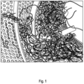
- Fig. 1 visualizes the problem. Metal threads make their way into the sieve and get stuck. The threads build up nests that eventually block the sieve inlet and holes in the sieve. Consequently, the recovery of the fine-grained part of the bottom ash will cease and the ilmenite is lost through the ash discharge.
- the threads originate from the waste fuel and have managed to pass the various magnets installed in the fuel preparation and transportation system.
- the reason is that pieces of e.g. copper, aluminium and stainless steel are not magnetic. This is a typical situation for waste fired boilers.
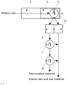
- Fig. 2 schematically shows a device according to the invention.
- a screw conveyor 1 conveys bottom ash from the boiler towards an end portion 2 in which the lower part of the circumference of the screw is circumferentially surrounded by a pre-sieve 3.
- Particulate material falling through the pre-sieve 3 is falling through the front part 4 of a chute comprising a division wall 5 separating front part 4 and rear part 6.
- This particulate material is then falling onto a sieve 7 as in the existing prior art system to mechanically separate coarse and fine particulate fraction.
- the fine particulate fraction is then further separated in a magnetic separator 8 as disclosed in WO 2018/188786 A1 .
- Threads and other elongated objects are moved by the conveyor screw over the pre-sieve 3 and fall off at the end of this pre-sieve into the rear part 6 of the chute leading towards an ash elevator and are being discarded.
- the location of the pre-sieve and the principal form is shown in Fig. 3 . It is a view from inside the classifier screw 2 looking down to the chute with the division wall 5 separating the path 4 to the existing sieve in the Improbed Loop TM system to the right and the path 6 to the ash elevator to the left.
- the pre-sieve 3 has the geometry of multiple fingers oriented in the axial direction of the screw. The pre-sieve is mounted just below the last part of the screw. Small particles, i.e. the accept fraction, are supposed to fall between the finger-type pre-sieve down to the sieve in the Improbed Loop TM system, whereas elongated objects and metal threads, i.e. the reject fraction, are moved by the screw over the pre-sieve to the chute leading to the ash elevator. The pre-sieve will hence be continuously cleaned by the screw. Therefore, no nesting of threads or other types of blockages caused by the ash can occur.
- the fingers are tapered in the flow direction in order to achieve an increasing gap between the fingers. This decreases the risk for blockages, e.g. due to formation of nests of metal threads.
- the sieve is formed to fit the screw diameter and is located just below the end part of the screw so that the screw continuously moves the material over the pre-sieve and prevents it from blocking the pre-sieve.
- the size of the gap between the screw and the pre-sieve preferably should be less than 5% of the conveyor screw diameter.
- the pre-sieve is designed for easy replacement.
- FIG. 6 An experimental test set up for testing the effectiveness of the pre-sieve according to the invention is shown in Fig. 6 .
- the screw 1 corresponds to the bottom ash screw in boiler P14. It was operated during the test with similar rpm (speed) as the P14 screw.
- the screw motor is controlled by a frequency converter.
- the casing of screw 1 has the inner diameter 231,9 mm and the diameter of the screw threads is 200,0 mm.
- An inspection box2 with two of the sides made of plexiglass, was mounted at the end of the screw.
- the screw was arranged with a 12° inclination upwards, i.e. like the inclination of the P14 screw.
- the pre-sieve 3 was mounted under the screw end, in the inspection box. In the series of tests, the two last tests were performed with the screw in horizontal position.
- a sieve with the mesh 0.71 mm was used for dividing a fraction of the bottom ash sample into two fractions; a finer passing the sieve and a coarser remaining on the sieve.
- the mass of the fractions was measured; 11400 g fine fraction and 15200 g coarse fraction.
- the two fractions were mixed again and approximately 300 g of metal scrap from the extra bucket, mainly metal threads, was added to the mixture.
- trials 1 through 6 the pre-sieve to be tested was mounted approximately 1 cm below the screw thread. In trials 7 and 8 the pre-sieve was moved down to a distance from the screw of 15-20 cm and bent to the angle 30° downwards. The idea was to test the function of the pre-sieve with the material falling by gravity onto and along the pre-sieve instead of being pushed upwards be the screw. Table 1. Operating parameters and settings in the 8 trials.
- Trial Sieve Screw inclination downstreams Screw speed (RPM) 1 Straight Upwards 0.92 2 Right Upwards 0.92 3 Right Upwards 0.92 4 Left Upwards 0.92 5 Left Upwards 0,92 6 Left Upwards 1.33 7 Straight / inclined and lower position Horizontal 0.92 + higher 8 Straight / inclined and lower position Downwards 0.92
- the operation was visually observed and recorded by a video camera.
- the mass of the fine and coarse fractions was measured.
- Trials 1 through 4 used the same operating conditions and settings except that the three different pre-sieves were used.
- the pre-sieve shall be self-cleaning. By locating the pre-sieve close to the screw and by tapering the pre-sieve fingers, the screw is supposed to remove fastened threads or nests from the pre-sieve and transport it to the end of the screw. Trial 5 aimed at testing this idea by simulating a case in which metal threads get stuck in the pre-sieve. A nest of threads was manually made and fastened in the pre-sieve.
- Trial 6 was like trial 4 except that the rotation speed of the screw was increased by 45%.
- Trials 7 and 8 were carried out in order to test if the self-cleaning function observed in trials 1 through 6 was necessary for the sieving performance or if similar good results could be obtained if the ash and metal scrap mixture was accelerated by gravity down onto the pre-sieve.
- the removal of scrap and threads is one of the important goals with installing the pre-sieve. Besides, it is important that the loss of fine material, potentially containing ilmenite, is low.
- the latter aspect was evaluated by measuring the mass of fine material in the reject box, after each trial, and comparing it with the total mass of fine material used in the trial.
- the loss, ⁇ was defined as by eq. 1 where m fine,reject is the mass of fine material in the reject and m fine,accept is the mass of fine material in the accept.
- ⁇ m fine , rejekt m fine , accept + m fine , reject ⁇ 100
- the pre-sieve arrangement in trials 7 and 8 did not work well.
- the performance with only gravel and sand type ash was acceptable but as soon as metal threads appeared in the ash stream problems occurred.
- the threads got stuck in the pre-sieve and blocked the ash flow.
- the threads contribute to form blockages with the ash particles, even with the finer ash.
- the threads act as reinforcement in the blockages.
- the entire pre-sieve surface is covered by blockages. The sieving function is lost, and the whole material flow goes to the reject box.
- Table 2 contains the measured accept and reject mass fractions in each of the eight tests and the loss of the fine particles to the reject, ⁇ , defined in Eq.1.
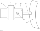
- Fig. 7 shows the mechanical impact device in the form of a piston-vibrator (9). It comprises a body (10) and a piston head (14).
- the piston-vibrator (9) is mounted to the casing of the bottom ash screw (not shown in Fig. 7 ) by means of the mounting (11).
- a rubber cushion (12) surrounds the body (10) of the piston-vibrator (9) in order to minimize vibrations induced from the casing of the bottom ash screw.
- the piston head (14) protrudes through a hole in the casing (15) and hits the pre-sieve on the inside of the casing (not shown). It is operated continuously.
- the pre-sieve can be inclined downwards in the direction of the end portion.
- the piston head (9) vibrates with a frequency of 1860 Hz at 2 bar and 2220 Hz at 6 bar pressure. It hits with a force of 50 to 200 N, preferably 80 to 150 N.
- the maximum sound pressure level is 80 dB(A), which is acceptable in a boiler house.
- the piston head (9) hits the pre-sieve with high frequency, it induces a vibration of the pre-sieve. This vibration prevents finer particles such as bottom ash from forming a layer of material on the pre-sieve.
Landscapes
- Engineering & Computer Science (AREA)
- Chemical & Material Sciences (AREA)
- Combustion & Propulsion (AREA)
- Mechanical Engineering (AREA)
- General Engineering & Computer Science (AREA)
- Combined Means For Separation Of Solids (AREA)
Claims (15)
- Vorrichtung zum kontinuierlichen Sortieren eines Partikelstroms, umfassend:a) eine Förderschnecke (1) zum Befördern des Partikelstroms zu einer Trennvorrichtung,b) ein Sieb (7) zum Auftrennen des Partikelstroms nach Größe,
ferner umfassendc) ein Vorsieb (3), das langgestreckte, von Fingern gebildete Sieböffnungen umfasst, die zu einem Endteil des Vorsiebs verlaufen, wobei die Spitzen der Finger in diesem Endteil nicht verbunden sind, wobei das Vorsieb (3) zwischen dem Auslass der Fördervorrichtung und dem Sieb angeordnet ist, undd) wobei der radiale Abstand zwischen der Förderschnecke (1) und dem Vorsieb (3) weniger als 10 %, vorzugsweise weniger als 5 %, des Förderschneckendurchmessers beträgt.
dadurch gekennzeichnet, dasse) das Vorsieb (3) einen Teil des Umfangs der Förderschnecke in einem axialen Endteil der Förderschnecke umschließt. - Vorrichtung gemäß Anspruch 1, dadurch gekennzeichnet, dass das Vorsieb (3) langgestreckte Sieböffnungen umfasst, die einen Winkel von -40° bis 40° mit der Förderrichtung der Förderschnecke einschließen.
- Vorrichtung gemäß Anspruch 1 oder 2, dadurch gekennzeichnet, dass die Breite der langgestreckten Öffnungen von der Basis zu der Spitze der Finger zunimmt.
- Vorrichtung gemäß Anspruch 3, dadurch gekennzeichnet, dass die Zunahme der Breite um einen Faktor von 2 bis 6, vorzugsweise von 3 bis 5, ist.
- Vorrichtung gemäß einem der Ansprüche 1 bis 4, umfassend wenigstens eines von:a) die Breite der langgestreckten Öffnungen an der Basis beträgt zwischen 1 und 5 mm, vorzugsweise 2 und 4 mm;b) die Breite der langgestreckten Öffnungen an der Spitze der Finger beträgt zwischen 4 und 20 mm, vorzugsweise 8 und 16 mm, bevorzugter 10 und 14 mm;c) die Länge der Finger von der Basis zu der Spitze beträgt zwischen 100 und 500 mm, vorzugsweise 100 und 400 mm, bevorzugter 150 und 250 mm;d) die Maschengröße des Siebs (7) beträgt zwischen 200 und 1.000 µm, vorzugsweise 300 und 800 µm.
- Vorrichtung gemäß einem der Ansprüche 1 bis 5, dadurch gekennzeichnet, dass sie ferner ein mechanisches Schlagwerk zur Bereitstellung von mechanischen Schlägen an das Vorsieb (3) umfasst.
- Vorrichtung gemäß Anspruch 6, dadurch gekennzeichnet, dass das mechanische Schlagwerk ein Hammer- oder Kolbenvibrator ist.
- Vorrichtung gemäß Anspruch 6 oder 7, dadurch gekennzeichnet, dass Schlagkraft und Schlagfrequenz des mechanischen Schlagwerks steuerbar sind.
- Vorrichtung gemäß einem der Ansprüche 6 bis 8, dadurch gekennzeichnet, dass das mechanische Schlagwerk Schläge in dem Bereich der Basis der Finger des Vorsiebs (3) bereitstellt.
- Verwendung der Vorrichtung gemäß einem der Ansprüche 1 bis 8 zum Auftrennen eines partikelförmigen Aschestroms aus einem Wirbelschichtkessel.
- Verfahren zum Betreiben eines Wirbelschichtkessels, umfassend die Schritte:a) Durchführen eines Wirbelschicht-Verbrennungsverfahrens;b) Entfernen wenigstens eines Aschestroms aus dem Wirbelschichtkessel;c) Auftrennen des Aschestroms in wenigstens zwei Fraktionen, wobei das Auftrennen einen Trennschritt unter Verwendung einer Vorrichtung gemäß einem der Ansprüche 1 bis 8 aufweist;d) Rezirkulieren einer abgetrennten Partikelfraktion in das Bett des Wirbelschichtkessels.
- Verfahren gemäß Anspruch 11, dadurch gekennzeichnet, dass der Kessel ein Zirkulations-Wirbelschichtkessel (CFB) oder ein stationärer Wirbelschichtkessel (BFB) ist.
- Verfahren gemäß Anspruch 11 oder 12, dadurch gekennzeichnet, dass die Wirbelschicht und der Aschestrom aus der Wirbelschicht Ilmenitpartikel umfassen und dass die abgetrennte rezirkulierte Partikelfraktion an Ilmenit angereichert ist.
- Verfahren gemäß Anspruch 13, dadurch gekennzeichnet, dass das Auftrennen einen Schritt der Verwendung eines Magnetabscheiders (12) einschließt
, der eine Feldstärke von 2.000 Gauss oder mehr, vorzugsweise 4.500 Gauss oder mehr, umfasst. - Verfahren gemäß Anspruch 13 oder 14, dadurch gekennzeichnet, dass der Anteil von Ilmenit in dem Bettmaterial 25 Gew.-% oder mehr, vorzugsweise 30 Gew.-% oder mehr, beträgt.
Applications Claiming Priority (2)
| Application Number | Priority Date | Filing Date | Title |
|---|---|---|---|
| EP20205149 | 2020-11-02 | ||
| PCT/EP2021/080398 WO2022090572A1 (en) | 2020-11-02 | 2021-11-02 | Device and method for sorting a particulate stream |
Publications (3)
| Publication Number | Publication Date |
|---|---|
| EP4237164A1 EP4237164A1 (de) | 2023-09-06 |
| EP4237164C0 EP4237164C0 (de) | 2025-01-01 |
| EP4237164B1 true EP4237164B1 (de) | 2025-01-01 |
Family
ID=73043161
Family Applications (2)
| Application Number | Title | Priority Date | Filing Date |
|---|---|---|---|
| EP21802704.3A Active EP4237164B1 (de) | 2020-11-02 | 2021-11-02 | Vorrichtung und verfahren zum sortieren eines partikelstroms |
| EP21802345.5A Active EP4237163B1 (de) | 2020-11-02 | 2021-11-02 | Vorrichtung und verfahren zum sortieren eines partikelstroms |
Family Applications After (1)
| Application Number | Title | Priority Date | Filing Date |
|---|---|---|---|
| EP21802345.5A Active EP4237163B1 (de) | 2020-11-02 | 2021-11-02 | Vorrichtung und verfahren zum sortieren eines partikelstroms |
Country Status (4)
| Country | Link |
|---|---|
| US (2) | US12196414B2 (de) |
| EP (2) | EP4237164B1 (de) |
| CN (2) | CN116367933B (de) |
| WO (2) | WO2022090571A1 (de) |
Families Citing this family (1)
| Publication number | Priority date | Publication date | Assignee | Title |
|---|---|---|---|---|
| CN116367933B (zh) * | 2020-11-02 | 2026-01-06 | 意昂能源基础设施公司 | 用于筛分颗粒流的装置和方法 |
Family Cites Families (36)
| Publication number | Priority date | Publication date | Assignee | Title |
|---|---|---|---|---|
| US856894A (en) | 1905-06-26 | 1907-06-11 | Merrell Soule Co | Corn-silking machine. |
| JPS53103864A (en) * | 1977-02-21 | 1978-09-09 | Satake Eng Co Ltd | Rotating type grain separator |
| GB1604221A (en) * | 1977-05-02 | 1981-12-02 | Appa Thermal Exchanges Ltd | Removal of ash from fluidised beds |
| DE3205366C2 (de) * | 1982-02-16 | 1984-06-07 | Deutsche Kommunal-Anlagen Miete GmbH, 8000 München | Austragsvorrichtung für einen Drehrohrofen |
| JPS6017192U (ja) | 1983-04-12 | 1985-02-05 | 岡村 静勇志 | すべり出し石けん箱 |
| FR2545385B3 (fr) | 1983-05-05 | 1986-07-25 | Raggi Jacques | Grille pour crible de premiere separation de calibrage pour produits heterogenes contenant des elements filiformes |
| US4839035A (en) * | 1988-02-25 | 1989-06-13 | Iafrate John A | Cylindrical screen separator with spirally arranged clearing and conveying blades |
| CA2007825C (en) * | 1989-03-01 | 1999-04-20 | Raymond W. Sherman | Material separating apparatus |
| DE4135864A1 (de) * | 1991-10-31 | 1993-05-06 | Metallgesellschaft Ag, 6000 Frankfurt, De | Vorrichtung zum trennen von hohlglaskoerpern und bruchmaterial |
| US5632380A (en) | 1995-10-17 | 1997-05-27 | Shaneway, Inc. | Ferrous material recovery system |
| AU8421398A (en) * | 1997-09-15 | 1999-03-25 | De Beers Consolidated Mines Limited | Sorting apparatus |
| DE19822991C2 (de) | 1998-05-22 | 2002-11-14 | Siemens Ag | Anlage zur Reststoffbehandlung |
| DE19822996C1 (de) * | 1998-05-22 | 1999-04-22 | Siemens Ag | Abscheidevorrichtung für langgestreckte Feststoffteile |
| DE19822993C2 (de) | 1998-05-22 | 2002-11-14 | Siemens Ag | Anlage zur Aufbereitung von Reststoff |
| US6221329B1 (en) * | 1999-03-09 | 2001-04-24 | Svedala Industries, Inc. | Pyrolysis process for reclaiming desirable materials from vehicle tires |
| JP2003251280A (ja) | 2002-03-06 | 2003-09-09 | Kubota Corp | 回転式スクリーン装置 |
| SE526412C2 (sv) * | 2003-02-03 | 2005-09-13 | Svante Bjoerk Ab | Arrangemang för avskiljning av partiklar, avskiljningsmetod samt arrangemang för optisk avsyning i samband med en process för tillverkning av elektriska kraftkablar |
| DE10335881A1 (de) | 2003-08-06 | 2005-03-03 | Huning Maschinenbau Gmbh | Fördervorrichtung mit Verstellsieb |
| IES20050413A2 (en) * | 2005-06-17 | 2006-12-29 | Aughey Res And Designs Ltd | A material screening apparatus |
| US7438188B2 (en) * | 2006-01-20 | 2008-10-21 | Wade Stolworthy | Device for use in placer mining operations and method |
| JP6017192B2 (ja) | 2012-06-19 | 2016-10-26 | 住友大阪セメント株式会社 | 回転篩装置 |
| GB2503233A (en) | 2012-06-19 | 2013-12-25 | Kek Gardner Ltd | Centrifugal sifting apparatus |
| JP5948223B2 (ja) | 2012-11-02 | 2016-07-06 | ユニ・チャーム株式会社 | 吸収性物品に係る材料の分離装置、及び分離方法 |
| CN205236354U (zh) | 2015-12-23 | 2016-05-18 | 江苏晨丰机电设备制造有限公司 | 粉料清理筛 |
| JP6722447B2 (ja) * | 2015-12-25 | 2020-07-15 | 川崎重工業株式会社 | グリズリ装置及び主灰排出システム |
| EP3266517A1 (de) * | 2016-07-07 | 2018-01-10 | Casale SA | Granulator für flüssige substanzen, insbesondere für harnstoff |
| DE102016225248A1 (de) * | 2016-12-16 | 2018-06-21 | Siltronic Ag | Abscheidevorrichtung für Polysilicium |
| EP3388744B1 (de) | 2017-04-12 | 2019-10-30 | Improbed AB | System und verfahren zum recycling von wirbelschichtkesselmaterial |
| EP3392564A1 (de) | 2017-04-19 | 2018-10-24 | Improbed AB | Verfahren zum betrieb eines wirbelbettkessels |
| CN108212797A (zh) * | 2017-12-06 | 2018-06-29 | 贵州中烟工业有限责任公司 | 一种烟用爆珠加工设备及其粒径筛选装置 |
| AU2018400359B2 (en) | 2018-01-04 | 2022-01-06 | Flsmidth A/S | Mobile crushing system having an eccentric roller crusher and finger screen |
| CN109290205A (zh) | 2018-09-18 | 2019-02-01 | 南县三缘米业有限公司 | 一种大米加工筛分装置 |
| CN209424016U (zh) | 2018-12-24 | 2019-09-24 | 高州创建铸造有限公司 | 一种原料筛粉机 |
| US20210008596A1 (en) * | 2019-04-03 | 2021-01-14 | Grainflow Dynamics Inc. | System and method for size separating conveyor |
| CN210146203U (zh) * | 2019-04-17 | 2020-03-17 | 福建南方路面机械有限公司 | 一种具有集成预筛装置的振动箅条式给料机 |
| CN116367933B (zh) * | 2020-11-02 | 2026-01-06 | 意昂能源基础设施公司 | 用于筛分颗粒流的装置和方法 |
-
2021
- 2021-11-02 CN CN202180074445.2A patent/CN116367933B/zh active Active
- 2021-11-02 EP EP21802704.3A patent/EP4237164B1/de active Active
- 2021-11-02 WO PCT/EP2021/080397 patent/WO2022090571A1/en not_active Ceased
- 2021-11-02 EP EP21802345.5A patent/EP4237163B1/de active Active
- 2021-11-02 US US18/032,398 patent/US12196414B2/en active Active
- 2021-11-02 US US18/032,215 patent/US12613029B2/en active Active
- 2021-11-02 CN CN202180074447.1A patent/CN116438019B/zh active Active
- 2021-11-02 WO PCT/EP2021/080398 patent/WO2022090572A1/en not_active Ceased
Also Published As
| Publication number | Publication date |
|---|---|
| WO2022090572A1 (en) | 2022-05-05 |
| US20240009705A1 (en) | 2024-01-11 |
| US20230392784A1 (en) | 2023-12-07 |
| EP4237164C0 (de) | 2025-01-01 |
| CN116367933A (zh) | 2023-06-30 |
| CN116367933B (zh) | 2026-01-06 |
| EP4237163B1 (de) | 2024-09-25 |
| EP4237163A1 (de) | 2023-09-06 |
| CN116438019B (zh) | 2026-03-17 |
| EP4237163C0 (de) | 2024-09-25 |
| US12613029B2 (en) | 2026-04-28 |
| WO2022090571A1 (en) | 2022-05-05 |
| CN116438019A (zh) | 2023-07-14 |
| US12196414B2 (en) | 2025-01-14 |
| EP4237164A1 (de) | 2023-09-06 |
Similar Documents
| Publication | Publication Date | Title |
|---|---|---|
| CN1418131B (zh) | 用于分离材料的方法和装置 | |
| KR830002053B1 (ko) | 산화철 환원으로부터의 배출폐기물내 미세 탄화물 입자회수를 위한 공기 세광(洗光) 방법 | |
| EP4237164B1 (de) | Vorrichtung und verfahren zum sortieren eines partikelstroms | |
| SK17272000A3 (sk) | Zariadenie na spracovanie zvyškového materiálu | |
| EP3091284B1 (de) | Vergasungsschmelzanlage | |
| JP3732429B2 (ja) | 灰溶融炉の前処理設備および前処理方法 | |
| JP6612655B2 (ja) | 流動層炉における流動媒体の処理方法および装置 | |
| CN110582672B (zh) | 用于操作流化床锅炉的方法 | |
| EP4037845B1 (de) | Vorrichtung zum sortieren von pulverteilchen | |
| JP2020073839A (ja) | 風力式分級装置 | |
| KR20010021279A (ko) | 가스화 용융로내에 생성되는 노바닥 잔사의 처리방법 | |
| JP3975041B2 (ja) | 熱分解残渣処理装置および廃棄物処理システム | |
| JP5308224B2 (ja) | 高炉ガス用ダストキャッチャ | |
| JP3909514B2 (ja) | ガス化溶融炉の炉底残渣の処理方法 | |
| JP3827976B2 (ja) | 灰溶融炉の前処理方法及び前処理装置 | |
| JP3732430B2 (ja) | 竪型破砕機の運転方法 | |
| JP2005066423A (ja) | 熱分解残渣分離装置 | |
| JP3137713U (ja) | 主灰の前処理設備 | |
| RU2251457C1 (ru) | Установка измельчения и сортировки материалов повышенной твердости, например металлического хрома | |
| JP2001153324A (ja) | ガス化溶融炉の炉底残渣の処理方法 | |
| RU36267U1 (ru) | Установка измельчения и сортировки материалов повышенной твердости, например, металлического хрома | |
| JP2024063580A (ja) | 振動ふるい装置、ストーカ式焼却炉及びストーカ式焼却炉の灰からの有価金属類の回収方法 | |
| PL395273A1 (pl) | Urzadzenie do czyszczenia i separacji drobnych odpadów metalurgicznych oraz sposób czyszczenia i separacji drobnych odpadów metalurgicznych | |
| PL190297B1 (pl) | Sposób i urządzenie do mielenia substancji stałych na sucho |
Legal Events
| Date | Code | Title | Description |
|---|---|---|---|
| STAA | Information on the status of an ep patent application or granted ep patent |
Free format text: STATUS: UNKNOWN |
|
| STAA | Information on the status of an ep patent application or granted ep patent |
Free format text: STATUS: THE INTERNATIONAL PUBLICATION HAS BEEN MADE |
|
| PUAI | Public reference made under article 153(3) epc to a published international application that has entered the european phase |
Free format text: ORIGINAL CODE: 0009012 |
|
| STAA | Information on the status of an ep patent application or granted ep patent |
Free format text: STATUS: REQUEST FOR EXAMINATION WAS MADE |
|
| 17P | Request for examination filed |
Effective date: 20230512 |
|
| AK | Designated contracting states |
Kind code of ref document: A1 Designated state(s): AL AT BE BG CH CY CZ DE DK EE ES FI FR GB GR HR HU IE IS IT LI LT LU LV MC MK MT NL NO PL PT RO RS SE SI SK SM TR |
|
| DAV | Request for validation of the european patent (deleted) | ||
| DAX | Request for extension of the european patent (deleted) | ||
| GRAP | Despatch of communication of intention to grant a patent |
Free format text: ORIGINAL CODE: EPIDOSNIGR1 |
|
| STAA | Information on the status of an ep patent application or granted ep patent |
Free format text: STATUS: GRANT OF PATENT IS INTENDED |
|
| INTG | Intention to grant announced |
Effective date: 20240626 |
|
| GRAJ | Information related to disapproval of communication of intention to grant by the applicant or resumption of examination proceedings by the epo deleted |
Free format text: ORIGINAL CODE: EPIDOSDIGR1 |
|
| STAA | Information on the status of an ep patent application or granted ep patent |
Free format text: STATUS: REQUEST FOR EXAMINATION WAS MADE |
|
| GRAP | Despatch of communication of intention to grant a patent |
Free format text: ORIGINAL CODE: EPIDOSNIGR1 |
|
| STAA | Information on the status of an ep patent application or granted ep patent |
Free format text: STATUS: GRANT OF PATENT IS INTENDED |
|
| INTC | Intention to grant announced (deleted) | ||
| GRAS | Grant fee paid |
Free format text: ORIGINAL CODE: EPIDOSNIGR3 |
|
| INTG | Intention to grant announced |
Effective date: 20240909 |
|
| GRAA | (expected) grant |
Free format text: ORIGINAL CODE: 0009210 |
|
| STAA | Information on the status of an ep patent application or granted ep patent |
Free format text: STATUS: THE PATENT HAS BEEN GRANTED |
|
| AK | Designated contracting states |
Kind code of ref document: B1 Designated state(s): AL AT BE BG CH CY CZ DE DK EE ES FI FR GB GR HR HU IE IS IT LI LT LU LV MC MK MT NL NO PL PT RO RS SE SI SK SM TR |
|
| REG | Reference to a national code |
Ref country code: GB Ref legal event code: FG4D |
|
| REG | Reference to a national code |
Ref country code: CH Ref legal event code: EP |
|
| REG | Reference to a national code |
Ref country code: DE Ref legal event code: R096 Ref document number: 602021024346 Country of ref document: DE |
|
| REG | Reference to a national code |
Ref country code: IE Ref legal event code: FG4D |
|
| U01 | Request for unitary effect filed |
Effective date: 20250120 |
|
| U07 | Unitary effect registered |
Designated state(s): AT BE BG DE DK EE FI FR IT LT LU LV MT NL PT RO SE SI Effective date: 20250124 |
|
| PG25 | Lapsed in a contracting state [announced via postgrant information from national office to epo] |
Ref country code: PL Free format text: LAPSE BECAUSE OF FAILURE TO SUBMIT A TRANSLATION OF THE DESCRIPTION OR TO PAY THE FEE WITHIN THE PRESCRIBED TIME-LIMIT Effective date: 20250101 |
|
| PG25 | Lapsed in a contracting state [announced via postgrant information from national office to epo] |
Ref country code: ES Free format text: LAPSE BECAUSE OF FAILURE TO SUBMIT A TRANSLATION OF THE DESCRIPTION OR TO PAY THE FEE WITHIN THE PRESCRIBED TIME-LIMIT Effective date: 20250101 |
|
| PG25 | Lapsed in a contracting state [announced via postgrant information from national office to epo] |
Ref country code: NO Free format text: LAPSE BECAUSE OF FAILURE TO SUBMIT A TRANSLATION OF THE DESCRIPTION OR TO PAY THE FEE WITHIN THE PRESCRIBED TIME-LIMIT Effective date: 20250401 Ref country code: IS Free format text: LAPSE BECAUSE OF FAILURE TO SUBMIT A TRANSLATION OF THE DESCRIPTION OR TO PAY THE FEE WITHIN THE PRESCRIBED TIME-LIMIT Effective date: 20250501 |
|
| PG25 | Lapsed in a contracting state [announced via postgrant information from national office to epo] |
Ref country code: HR Free format text: LAPSE BECAUSE OF FAILURE TO SUBMIT A TRANSLATION OF THE DESCRIPTION OR TO PAY THE FEE WITHIN THE PRESCRIBED TIME-LIMIT Effective date: 20250101 |
|
| PG25 | Lapsed in a contracting state [announced via postgrant information from national office to epo] |
Ref country code: GR Free format text: LAPSE BECAUSE OF FAILURE TO SUBMIT A TRANSLATION OF THE DESCRIPTION OR TO PAY THE FEE WITHIN THE PRESCRIBED TIME-LIMIT Effective date: 20250402 |
|
| PG25 | Lapsed in a contracting state [announced via postgrant information from national office to epo] |
Ref country code: CZ Free format text: LAPSE BECAUSE OF FAILURE TO SUBMIT A TRANSLATION OF THE DESCRIPTION OR TO PAY THE FEE WITHIN THE PRESCRIBED TIME-LIMIT Effective date: 20250101 |
|
| PG25 | Lapsed in a contracting state [announced via postgrant information from national office to epo] |
Ref country code: SM Free format text: LAPSE BECAUSE OF FAILURE TO SUBMIT A TRANSLATION OF THE DESCRIPTION OR TO PAY THE FEE WITHIN THE PRESCRIBED TIME-LIMIT Effective date: 20250101 |
|
| PG25 | Lapsed in a contracting state [announced via postgrant information from national office to epo] |
Ref country code: SK Free format text: LAPSE BECAUSE OF FAILURE TO SUBMIT A TRANSLATION OF THE DESCRIPTION OR TO PAY THE FEE WITHIN THE PRESCRIBED TIME-LIMIT Effective date: 20250101 |
|
| PLBE | No opposition filed within time limit |
Free format text: ORIGINAL CODE: 0009261 |
|
| STAA | Information on the status of an ep patent application or granted ep patent |
Free format text: STATUS: NO OPPOSITION FILED WITHIN TIME LIMIT |
|
| 26N | No opposition filed |
Effective date: 20251002 |
|
| U20 | Renewal fee for the european patent with unitary effect paid |
Year of fee payment: 5 Effective date: 20251117 |
|
| PGFP | Annual fee paid to national office [announced via postgrant information from national office to epo] |
Ref country code: GB Payment date: 20251120 Year of fee payment: 5 |