EP4237629B1 - Capsules de protection pour engins de chantier - Google Patents
Capsules de protection pour engins de chantier Download PDFInfo
- Publication number
- EP4237629B1 EP4237629B1 EP21801906.5A EP21801906A EP4237629B1 EP 4237629 B1 EP4237629 B1 EP 4237629B1 EP 21801906 A EP21801906 A EP 21801906A EP 4237629 B1 EP4237629 B1 EP 4237629B1
- Authority
- EP
- European Patent Office
- Prior art keywords
- capsule
- cavity
- cover
- walls
- axis
- Prior art date
- Legal status (The legal status is an assumption and is not a legal conclusion. Google has not performed a legal analysis and makes no representation as to the accuracy of the status listed.)
- Active
Links
Images




Classifications
-
- E—FIXED CONSTRUCTIONS
- E02—HYDRAULIC ENGINEERING; FOUNDATIONS; SOIL SHIFTING
- E02F—DREDGING; SOIL-SHIFTING
- E02F9/00—Component parts of dredgers or soil-shifting machines, not restricted to one of the kinds covered by groups E02F3/00 - E02F7/00
- E02F9/28—Small metalwork for digging elements, e.g. teeth scraper bits
- E02F9/2883—Wear elements for buckets or implements in general
-
- E—FIXED CONSTRUCTIONS
- E02—HYDRAULIC ENGINEERING; FOUNDATIONS; SOIL SHIFTING
- E02F—DREDGING; SOIL-SHIFTING
- E02F9/00—Component parts of dredgers or soil-shifting machines, not restricted to one of the kinds covered by groups E02F3/00 - E02F7/00
- E02F9/26—Indicating devices
- E02F9/267—Diagnosing or detecting failure of vehicles
-
- E—FIXED CONSTRUCTIONS
- E02—HYDRAULIC ENGINEERING; FOUNDATIONS; SOIL SHIFTING
- E02F—DREDGING; SOIL-SHIFTING
- E02F9/00—Component parts of dredgers or soil-shifting machines, not restricted to one of the kinds covered by groups E02F3/00 - E02F7/00
- E02F9/28—Small metalwork for digging elements, e.g. teeth scraper bits
- E02F9/2808—Teeth
- E02F9/2816—Mountings therefor
-
- H—ELECTRICITY
- H05—ELECTRIC TECHNIQUES NOT OTHERWISE PROVIDED FOR
- H05K—PRINTED CIRCUITS; CASINGS OR CONSTRUCTIONAL DETAILS OF ELECTRIC APPARATUS; MANUFACTURE OF ASSEMBLAGES OF ELECTRICAL COMPONENTS
- H05K5/00—Casings, cabinets or drawers for electric apparatus
- H05K5/0026—Casings, cabinets or drawers for electric apparatus provided with connectors and printed circuit boards [PCB], e.g. automotive electronic control units
- H05K5/0047—Casings, cabinets or drawers for electric apparatus provided with connectors and printed circuit boards [PCB], e.g. automotive electronic control units having a two-part housing enclosing a PCB
-
- E—FIXED CONSTRUCTIONS
- E02—HYDRAULIC ENGINEERING; FOUNDATIONS; SOIL SHIFTING
- E02F—DREDGING; SOIL-SHIFTING
- E02F9/00—Component parts of dredgers or soil-shifting machines, not restricted to one of the kinds covered by groups E02F3/00 - E02F7/00
- E02F9/26—Indicating devices
- E02F9/264—Sensors and their calibration for indicating the position of the work tool
-
- E—FIXED CONSTRUCTIONS
- E02—HYDRAULIC ENGINEERING; FOUNDATIONS; SOIL SHIFTING
- E02F—DREDGING; SOIL-SHIFTING
- E02F9/00—Component parts of dredgers or soil-shifting machines, not restricted to one of the kinds covered by groups E02F3/00 - E02F7/00
- E02F9/28—Small metalwork for digging elements, e.g. teeth scraper bits
- E02F9/2808—Teeth
- E02F9/2816—Mountings therefor
- E02F9/2825—Mountings therefor using adapters
Definitions
- the present disclosure relates to the field of earth moving machines. More particularly, the present disclosure relates to capsules for earth moving machines that, for instance, can be introduced in wear elements thereof or the digging implements, to name a few devices of said machines.
- Earth moving machines such as excavators or loaders, for example, comprise digging implements, e.g. bucket, shovel, dredgehead, etc., in which the material is pushed, pulled and/or collected.
- the digging implements e.g. the bucket
- the digging implements are subjected to high stresses and significant wear, mainly in the area referred to as blade.
- blades usually have a plurality of protective elements installed thereto which protect the blade and the digging implements against wear. Protective elements also increase the penetration of the digging implements into the terrain and the scratching of the terrain by the digging implements.
- wear elements All these elements are subjected to intense mechanical requirements, straining and heavy wear. For this reason, they usually must be replaced with certain frequency, when the wear experienced requires it. As a whole, these protective elements are usually referred to as wear elements or ground engaging tools, i.e. GETs.
- the different parts of the earth moving machine can include sensing devices that measure said magnitudes, e.g. the strain they are subjected to or any other parameter.
- the measurements and information resulting from processing the same remain within the location of the sensing devices, e.g. wear elements, traction means, a boom, a stick, a hydraulic cylinder, the digging implements, etc., since that is the location where the electronic devices for sensing are provided.
- wireless communications links are usually necessary to send the data to a remote device, for example a cabin of the earth moving machine, a control center, an Internet cloud, etc.
- devices of the machine like wear elements when devices of the machine like wear elements include sensing devices, they typically also include means for radiating and capturing electromagnetic waves such as RFID tags, antennas for near-field communications or antennas in the form of e.g. monopoles, in this way data of the sensing devices can be wirelessly communicated.
- electromagnetic waves such as RFID tags, antennas for near-field communications or antennas in the form of e.g. monopoles, in this way data of the sensing devices can be wirelessly communicated.
- the reach of the electromagnetic waves is usually limited.
- mechanical reliability of said antennas cannot be high enough so as to cope with the stresses that wear elements are subject to; also, the volume that said antennas require may preclude the integration thereof in certain devices like the wear elements, especially the lower the frequency of operation has to be.
- the WO2016/131015 pertains to a device and system for identifying and monitoring characteristics such as part identification, presence, condition, usage and/or performance of ground-engaging products such as ground engaging tools, wear plates, buckets, truck trays, and the like used on various kinds of earth working equipment.
- the system may include at least one monitoring device associated with a ground engaging product, at least one remote device to cooperate with the monitoring device, and programmable logic to process the information communicated between the devices.
- capsules for earth moving machines are also problematic.
- the cavities where capsules are typically introduced get deformed as a result of the stresses they are subjected to. This, in turn, results in the narrowing of the cavity or the opening thereof through which the capsule was introduced in the first place.
- soil and different solids or liquids tend to enter into the parts of the machine where the capsules are arranged. Especially the soil and other solid particles get compacted during operation of the machine and apply pressure on the capsules, which consequently deform.
- EP3715537 discloses a capsule for protecting an electronic device inside a wear element of an earth moving machine.
- the capsule comprises a container provided with an inner chamber for housing an electronic device, and has a front part provided with a flange, and a rear part.
- the capsule also comprises a cover that can be removably coupled to said container and configured for covering said rear part of said container.
- a first aspect of the disclosure relates to a capsule according to the subject-matter of claim 1, for protecting an electronic device for an earth moving machine, the capsule comprising: one or more walls arranged so as to form both an inner chamber configured for housing an electronic device, and an opening through which the inner chamber is accessed, the opening being at least partially covered by a cover, and wherein the one or more walls provide the capsule in at least one portion thereof with a geometry that is convex and adapted for allowing extraction of the capsule from a cavity of the earth moving machine by rotating the capsule about a rotating axis, where a cross-section of the capsule where the at least one portion starts extends over a plane defined by both the longitudinal axis of the capsule and an axis transverse thereto, the plane of the cross-section being parallel to said opening and to said cover, where the rotating axis is parallel to the axis transverse to the longitudinal axis.
- capsules in an earth moving machine When capsules in an earth moving machine are to undergo maintenance tasks, for instance for replacement of the electronic device or components thereof, or are to be either dismantled or decommissioned, for instance for recycling the capsule, they first need to be extracted from the cavity they are introduced.
- the present capsule which makes possible to protect an electronic device or one or more components thereof, can be extracted with more ease than other capsules owing to the geometry of the wall or walls thereof.
- the wall or walls can feature a cuboid or prismed shape, for example, that forms a protruding geometry; since the inner chamber is delimited by the wall or walls, the inner chamber protrudes as well.
- the rotation of the capsule is about a rotating axis such that, by applying a torque on the capsule to rotate it, the protruding geometry of the capsule does not collide or has reduced collisions with the geometry of the cavity.
- the capsule rotates several degrees so that at least a portion of the capsule protrudes is not lying flat within the cavity and, preferably, protrudes from the cavity, at which point the capsule can be pulled out manually or by means of a pulling device, e.g. claws, pliers, etc.
- the rotating axis is defined by way of axes of a cross-section of the capsule where the at least one portion starts. Said cross-section of the capsule extends over a plane defined by both the longitudinal axis of the capsule and an axis transverse thereto. The rotating axis is parallel to the axis transverse to the longitudinal axis.
- the cover comprises a slot antenna.
- the cover comprises or is of an electrically conductive material at least on a portion where the slot antenna is formed.
- the capsule thus further makes it possible to wirelessly transmit data of the electronic device to an electronic apparatus remote from the capsule and/or wirelessly receive data from a remote electronic apparatus and provide it to the electronic device.
- the electronic device and/or one or more components thereof are, for example but without limitation, one or more sensing devices, one or more batteries, one or more memory units, etc.
- the electronic apparatus can be a controller for supervising and/or operating the earth moving machine, and can be located e.g. in a control center, or in the earth moving machine, for example in a cabin thereof.
- the dielectric material can be part of the wall or walls where the slot antenna is formed, be part of one or more components adapted to fill the slot of the slot antenna in a removable manner, for example a removably couplable lid or cap, or be part of a filling material that fills both the slot and the inner chamber with the electronic device therein by way of e.g. a potting process. Concerning the latter, as the material also fills the inner chamber it likewise protects the electronic device within the inner chamber.
- the dielectric material preferably fills the slot as much as possible so as to hermetically seal the inner chamber, thereby reducing or completely preventing the ingress of particles of the soil, for instance, or other particles capable of short-circuiting or affecting the radioelectric performance of the slot antenna.
- the dielectric material can be, for instance, epoxy, silicone, plastic, etc.
- At least one of the walls of the capsule has a maximum length, i.e. the greatest dimension of the at least one of the walls where the slot antenna is arranged, in a particular longitudinal direction, a maximum width in a particular first transversal direction and a thickness in a second transversal direction, the maximum length is greater than or equal to the maximum width and the slot antenna has a maximum length, i.e. the greatest dimension of the slot antenna on the at least one of the walls, in the longitudinal direction which is at least 60% and is less than or equal to 100% of the maximum length of the at least one of the walls.
- the slot antenna is not a straight slot.
- the slot antenna can include a plurality of segments, each segment being connected to one or more other segments along the length thereof such that longitudinal directions of the respective segments forms an angle therebetween, that is to say, two directly adjacent segments are connected such that they are not parallel. In this way, the effective length of the slot antenna that will determine the frequency or frequencies of operation can be increased.
- the measurements and/or any estimations made therefrom can be used for supervision of the part or component of the machine, predicting maintenance therefor, informing an operator of the earth moving machine or within a control center of the ground engaging operations, controlling the earth moving machine (e.g. adjustments of the angle of attack, adjustments of the trajectory of digging implements when engaging the ground, adjustments of the force applied by the earth moving machine, etc.) by feeding the data to a controller that automatically adjusts operation of the earth moving machine, etc.
- controlling the earth moving machine e.g. adjustments of the angle of attack, adjustments of the trajectory of digging implements when engaging the ground, adjustments of the force applied by the earth moving machine, etc.
- the cap comprises a recess that fits within the one or more protruding surfaces of the cover.
- the capsule has a cuboid shape, and at least two opposite edges of the one or more walls are rounded.
- Figure 14A shows a perspective view of a capsule 10 according to embodiments
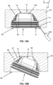
- Figures 14B and 14C show two different cross-sections of the capsule 10.
- the capsule 10 comprises one or more walls 15b that enclose an inner chamber 16.
- a cover 15a (for example, but without limitation, the first wall 15a of Figures 1-6 and 12A-12E ) on a first end 11 of the capsule 10 is to be mechanically coupled with the one or more walls 15b so as to at least partially cover an opening through which the inner chamber 16 is accessible.
- the cover 15a comprises a slot antenna, for example the slot antenna 20 as described with reference to previous Figures.
- Figure 18 shows a perspective view of a tooth 100 with magnets 91 arranged therein for cooperating with sensors of capsules in accordance with embodiments.
- the poka-yoke coupling member 55 is a protruding member that cooperates with a poka-yoke coupling member, in the form of a recess, in a cavity receiving the capsule 10.
- the cavity including said poka-yoke coupling member can be any one of the cavities described with reference to previous Figures.
- Figure 20 shows an imaginary box 500 enclosing a capsule 10 according to embodiments.
- the imaginary box 500 is represented with dashed lines for illustrative purposes only.
- the box 500 is a cube or a square cuboid with each of its six faces thereof being tangent to at least one point on the outer surface of at least one wall of the capsule 10.
- the imaginary box 500 is the box 500 having the minimum volume possible, i.e. the box 500 that simultaneously has faces tangent to at least one point on the outer surface of at least one wall of the capsule 10 and is minimally-sized.
- the capsule 10 includes a cap 70 like in the embodiments of Figure 20 , one or more faces of the box 500 may go through the cap 70 or not even touch it.
- Longitudinal, transverse and vertical axes (the latter two being also referred to as width and depth axes, or depth and width axes) of the capsule 10, and preferably of the geometry formed by the walls thereof, can be, for instance, defined by way of the imaginary box 500.
- the longest edge of the box 500 corresponds to a longitudinal axis of the capsule 10 (in this example, the longest edge is parallel to axis Y and has length L A , said length L A is likewise the maximum length measured along the longitudinal axis);
- a width axis of the capsule 10 preferably corresponds to an edge perpendicular thereto, and it is preferably the edge defining a plane containing (or parallel to a plane containing) with the end of a convex portion of the geometry of the capsule 10 (in this example, it defines top face 500a) and/or containing (or parallel to a plane containing) the opening of the capsule 10 (in this example, it defines bottom face 500b), which, in this example, is parallel to axis X and has length W A , said length W A is likewise the maximum length measured along the width axis; and a depth axis of the capsule 10 preferably corresponds to an edge perpendicular to both edges corresponding to the longitudinal and width axes, in this example being parallel
- the length of the edge corresponding to the width axis is shorter than the length of the edge corresponding to the depth axis. In some embodiments, the length of the edges corresponding to the width and depth axes is equal. In some less preferred embodiments, the length of the edge corresponding to the width axis is longer than the length of the edge corresponding to the depth axis.
- Figure 21 shows a cross-section of walls 15b forming a capsule according to embodiments in a portion thereof providing the capsule with a geometry that is convex.
- the cross-section is with respect to plane represented as A-A' in Figures 14B and 14C , and the view of Figure 21 is in the protruding direction D shown in Figures 14B and 14C , i.e. towards the inside of the capsule.
- the walls 15b enclose a two-dimensional area extending from the outermost side of the walls 15b and including the projection of the cavity 16, thus said area covers the entirety of the surface shown with striped patterns.
- Said area extends in the cross-section plane that is defined by two axes: the longitudinal axis (corresponding to the Y axis illustrated) and the width axis (corresponding to the X axis illustrated) of the capsule 10 as described e.g. with reference to Figure 20 .
- a length of the area along the longitudinal axis is shown as L C and the length of the area along the width axis is shown as W C .
Landscapes
- Engineering & Computer Science (AREA)
- Mining & Mineral Resources (AREA)
- Civil Engineering (AREA)
- General Engineering & Computer Science (AREA)
- Structural Engineering (AREA)
- Microelectronics & Electronic Packaging (AREA)
- Arrangements For Transmission Of Measured Signals (AREA)
- Medical Preparation Storing Or Oral Administration Devices (AREA)
- Manufacturing Of Micro-Capsules (AREA)
- Soil Working Implements (AREA)
- Lift-Guide Devices, And Elevator Ropes And Cables (AREA)
- Types And Forms Of Lifts (AREA)
- Catching Or Destruction (AREA)
- Vending Machines For Individual Products (AREA)
- Agricultural Chemicals And Associated Chemicals (AREA)
Claims (16)
- Capsule (10) de protection d'un dispositif électronique (30) pour un engin de terrassement (300), la capsule (10) comprenant une ou plusieurs parois (15b-15d) agencées de façon à former à la fois une chambre intérieure (16) configurée pour loger un dispositif électronique (30), et une ouverture à travers laquelle la chambre intérieure (16) est accessible, l'ouverture étant au moins partiellement recouverte par un couvercle (15a), caractérisée en ce que les une ou plusieurs parois (15b-15d) fournissent la capsule (10) dans au moins une partie de celles-ci avec une géométrie qui est convexe et adaptée pour permettre l'extraction de la capsule (10) à partir d'une cavité (97, 125-127, 225-229) de l'engin de terrassement (300) par rotation de la capsule (10) autour d'un axe de rotation (R1), où une section transversale de la capsule (10) où commence l'au moins une partie s'étend sur un plan défini à la fois par l'axe longitudinal (Y) de la capsule (10) et un axe (X) transversal à celui-ci, le plan de la section transversale étant parallèle à ladite ouverture et audit couvercle (15a), où l'axe de rotation (R1) est parallèle à l'axe (X) transversal à l'axe longitudinal (Y).
- Capsule (10) selon la revendication 1, dans laquelle l'ouverture et le couvercle de la capsule (10) sont définis dans la longueur maximale le long de l'axe longitudinal (Y).
- Capsule (10) selon la revendication 1 ou la revendication 2, dans laquelle le couvercle (15a) se trouve sur une première extrémité (11) de la capsule (10) et la géométrie est convexe vers une deuxième extrémité (12) de la capsule (10), la deuxième extrémité (12) étant opposée à la première extrémité (11).
- Capsule (10) selon l'une quelconque des revendications précédentes, dans laquelle le couvercle (15a) comprend une ou plusieurs surfaces saillantes (65) pour permettre à un outil d'extraction (400) d'appliquer un couple sur celles-ci afin d'extraire la capsule (10) à partir de la cavité (97, 125-127, 225-229), les une ou plusieurs surfaces saillantes (65) s'étendant parallèlement à une surface la plus grande du couvercle (15a).
- Capsule (10) selon l'une quelconque des revendications précédentes, dans laquelle la capsule (10) comprend en outre un capuchon (70) pouvant être accouplé de manière amovible au couvercle (15a), le capuchon (70) comprenant une ou plusieurs saillies (71) pour entrer en contact avec les parois (99) de la cavité (97, 125-127, 225-229), lorsque la cavité est formée et dimensionnée selon une forme et des dimensions de la capsule.
- Capsule (10) selon l'une quelconque des revendications précédentes, dans laquelle la capsule (10) présente une forme cuboïde et deux bords opposés des une ou plusieurs parois (15b-15d) sont arrondis ou chanfreinés.
- Capsule (10) selon l'une quelconque des revendications précédentes, dans laquelle le couvercle (15a) est doté d'un ou plusieurs bords (17a-17d) et les un ou plusieurs bords (17a-17d) sont perpendiculaires à la surface la plus grande du couvercle (15a).
- Capsule (10) selon l'une quelconque des revendications précédentes, dans laquelle le couvercle (15a) comprend une antenne à fente (20).
- Dispositif (95, 100, 200, 301-307) pour un engin de terrassement (300) comprenant : une cavité (97, 125-127, 225-229) ; et la capsule (10) selon l'une quelconque des revendications 1 à 8, la capsule pouvant être introduite dans la cavité (97, 125-127, 225-229), caractérisé en ce que la géométrie de l'au moins une partie de la capsule (10) s'ajuste dans au moins une partie de la cavité (97, 125-127, 225-229), et une géométrie (98) de l'au moins une partie de la cavité est adaptée pour permettre l'extraction de la capsule (10) à partir de la cavité (97, 125-127, 225-229) par rotation de la capsule (10) autour de l'axe de rotation (R1).
- Dispositif selon la revendication 9, dans lequel la géométrie (98) de l'au moins une partie de la capsule (10) et de l'au moins une partie de la cavité (97, 125-127, 225-229) est adaptée pour permettre l'extraction de la capsule (10) à partir de la cavité (97, 125-127, 225-229) avec l'application d'une force ou d'une pression sur le couvercle (15a) décalée par rapport au milieu du couvercle (15) qui résulte en un couple qui a tendance à faire tourner la capsule (10) à extraire autour de l'axe de rotation (R1).
- Dispositif selon l'une quelconque des revendications 9 à 10, dans lequel le dispositif (100, 200, 301-307) est un élément d'usure comprenant un adaptateur ou un adaptateur intermédiaire (200), l'adaptateur ou l'adaptateur intermédiaire (200) ayant une partie mâle (205) adaptée pour être insérée dans une partie femelle (110) d'une dent (100) et délimitant une première extrémité de l'élément d'usure, et une partie arrière (207) délimitant une deuxième extrémité (202) de l'élément d'usure, dans lequel la cavité (97, 225-227) est agencée à un emplacement dans la partie mâle (205), l'emplacement étant :une surface (206) au niveau d'une extrémité de mise en prise de dent (201) ; ouadjacent à un trou traversant (220) de l'adaptateur ou de l'adaptateur intermédiaire (200) pour recevoir une goupille pour l'accouplement mécanique de l'adaptateur ou de l'adaptateur intermédiaire (200) à la dent (100), et entre le trou traversant (220) et la deuxième extrémité (202) ; ouadjacent au trou traversant (220), et entre le trou traversant (220) et l'extrémité de mise en prise de dent (201).
- Ensemble comprenant : un premier dispositif (95, 100, 200, 301-307) selon l'une quelconque des revendications 9 à 11, et un deuxième dispositif (95, 100, 200, 301-307) pour un engin de terrassement, le deuxième dispositif étant fixé ou pouvant être fixé au premier dispositif ; la capsule (10) du premier dispositif comprenant au moins un capteur à effet Hall situé chacun sur une rainure des une ou plusieurs rainures (25), et le deuxième dispositif comprenant un ou plusieurs aimants (91) agencés de sorte que chaque aimant (91) se trouve à une distance d'un capteur à effet Hall lorsque le deuxième dispositif est fixé au premier dispositif, la distance étant inférieure à 5 cm.
- Processus comprenant : la fabrication d'une capsule (10) de protection d'un dispositif électronique (30) pour un engin de terrassement (300), la capsule (10) comprenant une ou plusieurs parois (15b-15d) agencées de façon à former à la fois une chambre intérieure (16) configurée pour loger un dispositif électronique (30), et une ouverture à travers laquelle la chambre intérieure (16) est accessible ; la formation d'un couvercle (15a) ; l'accouplement du couvercle (15a) aux une ou plusieurs parois (15b-15d) de façon à recouvrir au moins partiellement l'ouverture ; caractérisé par la formation des une ou plusieurs parois (15b-15d) de sorte que la capsule (10) comprenne, dans au moins une partie de celle-ci, une géométrie convexe et adaptée pour permettre l'extraction de la capsule (10) à partir d'une cavité (97, 125-127, 225-229) de l'engin de terrassement (300) par rotation de la capsule (10) autour d'un axe de rotation (R1), où une section transversale de la capsule (10) où commence l'au moins une partie s'étend sur un plan défini à la fois par l'axe longitudinal (Y) de la capsule (10) et un axe (X) transversal à celui-ci, le plan de la section transversale étant parallèle à ladite ouverture et audit couvercle (15a), où l'axe de rotation (R1) est parallèle à l'axe (X) transversal à l'axe longitudinal (Y).
- Processus selon la revendication 13, dans lequel la capsule (10) est fabriquée avec un processus d'enrobage où l'enrobage est réalisé dans un moule formé selon la capsule (10).
- Processus selon la revendication 14, comprenant en outre : l'agencement d'un dispositif (95, 100, 200, 301-307) pour un engin de terrassement (300) ; la formation de la cavité (97, 125-127, 225-229) dans le dispositif (95) dans lequel la capsule (10) peut être introduite dans la cavité (97, 125-127, 225-229), dans lequel la cavité (97, 125-127, 225-229) est formée de sorte que la géométrie de l'au moins une partie de la capsule (10) s'ajuste dans au moins une partie de la cavité (97, 125-127, 225-229), dans lequel une géométrie (98) de l'au moins une partie de la cavité est adaptée pour permettre l'extraction de la capsule (10) à partir de la cavité (97, 125-127, 225-229) par rotation de la capsule (10) autour de l'axe de rotation (R1).
- Processus d'extraction d'une capsule selon la revendication 4, ou selon l'une quelconque des revendications 5 à 8 lorsqu'elle dépend directement ou indirectement de la revendication 4, à partir d'un dispositif selon l'une quelconque des revendications 9 à 11, le procédé comprenant : pendant que la capsule (10) est introduite dans la cavité (97, 125-127, 225-229) de sorte qu'une première extrémité (11) de la capsule (10) soit orientée vers l'extérieur à partir de la cavité, l'agencement d'un outil d'extraction (400) sur l'une des une ou plusieurs surfaces saillantes (65) du couvercle (15a) et l'application d'un couple sur celle-ci pour extraire la capsule (10) à partir de la cavité par rotation de la capsule (10) autour de l'axe de rotation (R1) ; dans lequel le couvercle (15a) se trouve sur la première extrémité (11) de la capsule (10) et la géométrie de l'au moins une partie de la capsule (10) est convexe vers une deuxième extrémité (12) de la capsule (10), la deuxième extrémité (12) étant opposée à la première extrémité (11).
Applications Claiming Priority (3)
| Application Number | Priority Date | Filing Date | Title |
|---|---|---|---|
| EP20382939 | 2020-10-28 | ||
| EP21382114 | 2021-02-12 | ||
| PCT/EP2021/080027 WO2022090411A1 (fr) | 2020-10-28 | 2021-10-28 | Capsules de protection pour machines de terrassement |
Publications (3)
| Publication Number | Publication Date |
|---|---|
| EP4237629A1 EP4237629A1 (fr) | 2023-09-06 |
| EP4237629B1 true EP4237629B1 (fr) | 2025-04-02 |
| EP4237629C0 EP4237629C0 (fr) | 2025-04-02 |
Family
ID=78500626
Family Applications (1)
| Application Number | Title | Priority Date | Filing Date |
|---|---|---|---|
| EP21801906.5A Active EP4237629B1 (fr) | 2020-10-28 | 2021-10-28 | Capsules de protection pour engins de chantier |
Country Status (9)
| Country | Link |
|---|---|
| US (1) | US12612769B2 (fr) |
| EP (1) | EP4237629B1 (fr) |
| AU (1) | AU2021370385B2 (fr) |
| CA (1) | CA3195215A1 (fr) |
| CL (1) | CL2023001211A1 (fr) |
| ES (1) | ES3033624T3 (fr) |
| MX (1) | MX2023004945A (fr) |
| PE (1) | PE20231287A1 (fr) |
| WO (1) | WO2022090411A1 (fr) |
Families Citing this family (2)
| Publication number | Priority date | Publication date | Assignee | Title |
|---|---|---|---|---|
| US12188210B2 (en) * | 2020-03-27 | 2025-01-07 | Metalogenia Research & Technologies S.L. | Capsule for protecting an electronic device inside a wear element of an earth moving machine |
| EP4553238A3 (fr) * | 2020-10-28 | 2025-07-16 | Metalogenia Research & Technologies S.L. | Capsules de protection pour engins de chantier avec une antenne à fente |
Citations (5)
| Publication number | Priority date | Publication date | Assignee | Title |
|---|---|---|---|---|
| WO2012116408A1 (fr) * | 2011-03-01 | 2012-09-07 | Encore Automation Pty Ltd | Système de détection |
| WO2016131015A2 (fr) * | 2015-02-13 | 2016-08-18 | Esco Corporation | Surveillance de produits d'attaque du sol destinés à un équipement de terrassement |
| WO2017017289A1 (fr) * | 2015-07-24 | 2017-02-02 | Metalogenia Research & Technologies S.L. | Capteur d'usure et élément d'usure, et ensemble et utilisation correspondants |
| CN108387641A (zh) * | 2017-02-02 | 2018-08-10 | 卡特彼勒公司 | 超声感测地面接合工具的磨损寿命 |
| EP3715537A1 (fr) * | 2019-03-29 | 2020-09-30 | Metalogenia Research & Technologies S.L. | Capsule pour protéger un dispositif électronique à l'intérieur d'un élément d'usure d'un engin de terrassement |
Family Cites Families (4)
| Publication number | Priority date | Publication date | Assignee | Title |
|---|---|---|---|---|
| CL2011000274A1 (es) | 2011-02-08 | 2011-05-20 | Sergio Monzon Osorio 90% | Sistema de alarma para detectar el desprendimiento de dientes y/o adaptadores en cucharones de palas de retroexcavacion. |
| DE102012016004B4 (de) | 2012-08-11 | 2017-12-28 | Identec Solutions Ag | Verfahren und Vorrichtung zur Erfassung der Anwesenheit von steinbrechenden Werkzeugen an Erdbewegungsmaschinen |
| AR119029A1 (es) * | 2019-05-31 | 2021-11-17 | Esco Group Llc | Monitoreo de productos de corte para equipos de movimiento de tierra |
| JP2022537174A (ja) | 2019-06-17 | 2022-08-24 | エスコ・グループ・エルエルシー | 地面係合製品の監視 |
-
2021
- 2021-10-28 CA CA3195215A patent/CA3195215A1/fr active Pending
- 2021-10-28 ES ES21801906T patent/ES3033624T3/es active Active
- 2021-10-28 WO PCT/EP2021/080027 patent/WO2022090411A1/fr not_active Ceased
- 2021-10-28 US US18/250,986 patent/US12612769B2/en active Active
- 2021-10-28 MX MX2023004945A patent/MX2023004945A/es unknown
- 2021-10-28 AU AU2021370385A patent/AU2021370385B2/en active Active
- 2021-10-28 EP EP21801906.5A patent/EP4237629B1/fr active Active
- 2021-10-28 PE PE2023001511A patent/PE20231287A1/es unknown
-
2023
- 2023-04-27 CL CL2023001211A patent/CL2023001211A1/es unknown
Patent Citations (5)
| Publication number | Priority date | Publication date | Assignee | Title |
|---|---|---|---|---|
| WO2012116408A1 (fr) * | 2011-03-01 | 2012-09-07 | Encore Automation Pty Ltd | Système de détection |
| WO2016131015A2 (fr) * | 2015-02-13 | 2016-08-18 | Esco Corporation | Surveillance de produits d'attaque du sol destinés à un équipement de terrassement |
| WO2017017289A1 (fr) * | 2015-07-24 | 2017-02-02 | Metalogenia Research & Technologies S.L. | Capteur d'usure et élément d'usure, et ensemble et utilisation correspondants |
| CN108387641A (zh) * | 2017-02-02 | 2018-08-10 | 卡特彼勒公司 | 超声感测地面接合工具的磨损寿命 |
| EP3715537A1 (fr) * | 2019-03-29 | 2020-09-30 | Metalogenia Research & Technologies S.L. | Capsule pour protéger un dispositif électronique à l'intérieur d'un élément d'usure d'un engin de terrassement |
Also Published As
| Publication number | Publication date |
|---|---|
| US12612769B2 (en) | 2026-04-28 |
| MX2023004945A (es) | 2023-05-24 |
| CA3195215A1 (fr) | 2022-05-05 |
| ES3033624T3 (en) | 2025-08-06 |
| EP4237629C0 (fr) | 2025-04-02 |
| CL2023001211A1 (es) | 2023-11-24 |
| US20240011254A1 (en) | 2024-01-11 |
| WO2022090411A1 (fr) | 2022-05-05 |
| AU2021370385B2 (en) | 2025-05-08 |
| AU2021370385A1 (en) | 2023-05-25 |
| PE20231287A1 (es) | 2023-08-22 |
| EP4237629A1 (fr) | 2023-09-06 |
Similar Documents
| Publication | Publication Date | Title |
|---|---|---|
| EP4237629B1 (fr) | Capsules de protection pour engins de chantier | |
| EP3976892B1 (fr) | Surveillance de produits entrant en contact avec le sol pour équipement de terrassement | |
| US20260049462A1 (en) | Protective capsules for earth moving machines having a slot antenna | |
| EP4647558A2 (fr) | Ensembles d'éléments d'usure pour machines de terrassement à connexion câblée et dispositif de protection associé | |
| EP3992376B1 (fr) | Appareils pour machines de terrassement avec des capacités de transmission de données | |
| AU2021333657A1 (en) | Monitoring ground-engaging products for earth working equipment | |
| RU2847362C1 (ru) | Капсула для защиты электронного устройства для землеройной машины, устройство для землеройной машины, содержащее такую капсулу, способ изготовления такой капсулы, система для контроля степени износа одного или более устройств землеройной машины, устройство с функциональными возможностями беспроводной передачи и/или приема для землеройной машины, устройство для землеройной машины, содержащее такое устройство, способ установки такого устройства в полости землеройной машины и землеройная машина | |
| CN116685745A (zh) | 土方机械的保护性舱盒 | |
| BR112023007920B1 (pt) | Cápsulas de proteção para máquinas de movimentação de terra | |
| JP2023549707A5 (fr) |
Legal Events
| Date | Code | Title | Description |
|---|---|---|---|
| STAA | Information on the status of an ep patent application or granted ep patent |
Free format text: STATUS: UNKNOWN |
|
| STAA | Information on the status of an ep patent application or granted ep patent |
Free format text: STATUS: THE INTERNATIONAL PUBLICATION HAS BEEN MADE |
|
| PUAI | Public reference made under article 153(3) epc to a published international application that has entered the european phase |
Free format text: ORIGINAL CODE: 0009012 |
|
| STAA | Information on the status of an ep patent application or granted ep patent |
Free format text: STATUS: REQUEST FOR EXAMINATION WAS MADE |
|
| 17P | Request for examination filed |
Effective date: 20230526 |
|
| AK | Designated contracting states |
Kind code of ref document: A1 Designated state(s): AL AT BE BG CH CY CZ DE DK EE ES FI FR GB GR HR HU IE IS IT LI LT LU LV MC MK MT NL NO PL PT RO RS SE SI SK SM TR |
|
| DAV | Request for validation of the european patent (deleted) | ||
| DAX | Request for extension of the european patent (deleted) | ||
| GRAP | Despatch of communication of intention to grant a patent |
Free format text: ORIGINAL CODE: EPIDOSNIGR1 |
|
| STAA | Information on the status of an ep patent application or granted ep patent |
Free format text: STATUS: GRANT OF PATENT IS INTENDED |
|
| INTG | Intention to grant announced |
Effective date: 20240524 |
|
| GRAJ | Information related to disapproval of communication of intention to grant by the applicant or resumption of examination proceedings by the epo deleted |
Free format text: ORIGINAL CODE: EPIDOSDIGR1 |
|
| STAA | Information on the status of an ep patent application or granted ep patent |
Free format text: STATUS: REQUEST FOR EXAMINATION WAS MADE |
|
| GRAP | Despatch of communication of intention to grant a patent |
Free format text: ORIGINAL CODE: EPIDOSNIGR1 |
|
| STAA | Information on the status of an ep patent application or granted ep patent |
Free format text: STATUS: GRANT OF PATENT IS INTENDED |
|
| INTC | Intention to grant announced (deleted) | ||
| RIN1 | Information on inventor provided before grant (corrected) |
Inventor name: FERRANDIZ BORRAS, VICENT Inventor name: GIMENO TORDERA, ALBERT Inventor name: MARQUEZ LLINAS, JORDI |
|
| INTG | Intention to grant announced |
Effective date: 20241023 |
|
| GRAS | Grant fee paid |
Free format text: ORIGINAL CODE: EPIDOSNIGR3 |
|
| GRAA | (expected) grant |
Free format text: ORIGINAL CODE: 0009210 |
|
| STAA | Information on the status of an ep patent application or granted ep patent |
Free format text: STATUS: THE PATENT HAS BEEN GRANTED |
|
| AK | Designated contracting states |
Kind code of ref document: B1 Designated state(s): AL AT BE BG CH CY CZ DE DK EE ES FI FR GB GR HR HU IE IS IT LI LT LU LV MC MK MT NL NO PL PT RO RS SE SI SK SM TR |
|
| REG | Reference to a national code |
Ref country code: GB Ref legal event code: FG4D |
|
| REG | Reference to a national code |
Ref country code: CH Ref legal event code: EP |
|
| REG | Reference to a national code |
Ref country code: DE Ref legal event code: R096 Ref document number: 602021028620 Country of ref document: DE |
|
| REG | Reference to a national code |
Ref country code: IE Ref legal event code: FG4D |
|
| U01 | Request for unitary effect filed |
Effective date: 20250430 |
|
| U07 | Unitary effect registered |
Designated state(s): AT BE BG DE DK EE FI FR IT LT LU LV MT NL PT RO SE SI Effective date: 20250508 |
|
| REG | Reference to a national code |
Ref country code: ES Ref legal event code: FG2A Ref document number: 3033624 Country of ref document: ES Kind code of ref document: T3 Effective date: 20250806 |
|
| PG25 | Lapsed in a contracting state [announced via postgrant information from national office to epo] |
Ref country code: NO Free format text: LAPSE BECAUSE OF FAILURE TO SUBMIT A TRANSLATION OF THE DESCRIPTION OR TO PAY THE FEE WITHIN THE PRESCRIBED TIME-LIMIT Effective date: 20250702 Ref country code: GR Free format text: LAPSE BECAUSE OF FAILURE TO SUBMIT A TRANSLATION OF THE DESCRIPTION OR TO PAY THE FEE WITHIN THE PRESCRIBED TIME-LIMIT Effective date: 20250703 |
|
| PG25 | Lapsed in a contracting state [announced via postgrant information from national office to epo] |
Ref country code: PL Free format text: LAPSE BECAUSE OF FAILURE TO SUBMIT A TRANSLATION OF THE DESCRIPTION OR TO PAY THE FEE WITHIN THE PRESCRIBED TIME-LIMIT Effective date: 20250402 |
|
| PG25 | Lapsed in a contracting state [announced via postgrant information from national office to epo] |
Ref country code: HR Free format text: LAPSE BECAUSE OF FAILURE TO SUBMIT A TRANSLATION OF THE DESCRIPTION OR TO PAY THE FEE WITHIN THE PRESCRIBED TIME-LIMIT Effective date: 20250402 |
|
| PG25 | Lapsed in a contracting state [announced via postgrant information from national office to epo] |
Ref country code: RS Free format text: LAPSE BECAUSE OF FAILURE TO SUBMIT A TRANSLATION OF THE DESCRIPTION OR TO PAY THE FEE WITHIN THE PRESCRIBED TIME-LIMIT Effective date: 20250702 |
|
| PG25 | Lapsed in a contracting state [announced via postgrant information from national office to epo] |
Ref country code: IS Free format text: LAPSE BECAUSE OF FAILURE TO SUBMIT A TRANSLATION OF THE DESCRIPTION OR TO PAY THE FEE WITHIN THE PRESCRIBED TIME-LIMIT Effective date: 20250802 |
|
| U20 | Renewal fee for the european patent with unitary effect paid |
Year of fee payment: 5 Effective date: 20251027 |
|
| PG25 | Lapsed in a contracting state [announced via postgrant information from national office to epo] |
Ref country code: SM Free format text: LAPSE BECAUSE OF FAILURE TO SUBMIT A TRANSLATION OF THE DESCRIPTION OR TO PAY THE FEE WITHIN THE PRESCRIBED TIME-LIMIT Effective date: 20250402 |
|
| PG25 | Lapsed in a contracting state [announced via postgrant information from national office to epo] |
Ref country code: CZ Free format text: LAPSE BECAUSE OF FAILURE TO SUBMIT A TRANSLATION OF THE DESCRIPTION OR TO PAY THE FEE WITHIN THE PRESCRIBED TIME-LIMIT Effective date: 20250402 |
|
| PG25 | Lapsed in a contracting state [announced via postgrant information from national office to epo] |
Ref country code: SK Free format text: LAPSE BECAUSE OF FAILURE TO SUBMIT A TRANSLATION OF THE DESCRIPTION OR TO PAY THE FEE WITHIN THE PRESCRIBED TIME-LIMIT Effective date: 20250402 |
|
| PGFP | Annual fee paid to national office [announced via postgrant information from national office to epo] |
Ref country code: ES Payment date: 20251103 Year of fee payment: 5 |
|
| PLBE | No opposition filed within time limit |
Free format text: ORIGINAL CODE: 0009261 |
|
| STAA | Information on the status of an ep patent application or granted ep patent |
Free format text: STATUS: NO OPPOSITION FILED WITHIN TIME LIMIT |
|
| REG | Reference to a national code |
Ref country code: CH Ref legal event code: L10 Free format text: ST27 STATUS EVENT CODE: U-0-0-L10-L00 (AS PROVIDED BY THE NATIONAL OFFICE) Effective date: 20260211 |
|
| 26N | No opposition filed |
Effective date: 20260105 |