EP4238433A1 - Appareil de génération d'aérosol - Google Patents
Appareil de génération d'aérosol Download PDFInfo
- Publication number
- EP4238433A1 EP4238433A1 EP21885160.8A EP21885160A EP4238433A1 EP 4238433 A1 EP4238433 A1 EP 4238433A1 EP 21885160 A EP21885160 A EP 21885160A EP 4238433 A1 EP4238433 A1 EP 4238433A1
- Authority
- EP
- European Patent Office
- Prior art keywords
- heating element
- change rate
- preset
- resistance
- resistance change
- Prior art date
- Legal status (The legal status is an assumption and is not a legal conclusion. Google has not performed a legal analysis and makes no representation as to the accuracy of the status listed.)
- Pending
Links
Images


Classifications
-
- A—HUMAN NECESSITIES
- A24—TOBACCO; CIGARS; CIGARETTES; SIMULATED SMOKING DEVICES; SMOKERS' REQUISITES
- A24F—SMOKERS' REQUISITES; MATCH BOXES; SIMULATED SMOKING DEVICES
- A24F40/00—Electrically operated smoking devices; Component parts thereof; Manufacture thereof; Maintenance or testing thereof; Charging means specially adapted therefor
- A24F40/50—Control or monitoring
- A24F40/53—Monitoring, e.g. fault detection
-
- A—HUMAN NECESSITIES
- A24—TOBACCO; CIGARS; CIGARETTES; SIMULATED SMOKING DEVICES; SMOKERS' REQUISITES
- A24F—SMOKERS' REQUISITES; MATCH BOXES; SIMULATED SMOKING DEVICES
- A24F40/00—Electrically operated smoking devices; Component parts thereof; Manufacture thereof; Maintenance or testing thereof; Charging means specially adapted therefor
- A24F40/10—Devices using liquid inhalable precursors
-
- A—HUMAN NECESSITIES
- A24—TOBACCO; CIGARS; CIGARETTES; SIMULATED SMOKING DEVICES; SMOKERS' REQUISITES
- A24F—SMOKERS' REQUISITES; MATCH BOXES; SIMULATED SMOKING DEVICES
- A24F40/00—Electrically operated smoking devices; Component parts thereof; Manufacture thereof; Maintenance or testing thereof; Charging means specially adapted therefor
- A24F40/40—Constructional details, e.g. connection of cartridges and battery parts
-
- A—HUMAN NECESSITIES
- A24—TOBACCO; CIGARS; CIGARETTES; SIMULATED SMOKING DEVICES; SMOKERS' REQUISITES
- A24F—SMOKERS' REQUISITES; MATCH BOXES; SIMULATED SMOKING DEVICES
- A24F40/00—Electrically operated smoking devices; Component parts thereof; Manufacture thereof; Maintenance or testing thereof; Charging means specially adapted therefor
- A24F40/40—Constructional details, e.g. connection of cartridges and battery parts
- A24F40/42—Cartridges or containers for inhalable precursors
-
- A—HUMAN NECESSITIES
- A24—TOBACCO; CIGARS; CIGARETTES; SIMULATED SMOKING DEVICES; SMOKERS' REQUISITES
- A24F—SMOKERS' REQUISITES; MATCH BOXES; SIMULATED SMOKING DEVICES
- A24F40/00—Electrically operated smoking devices; Component parts thereof; Manufacture thereof; Maintenance or testing thereof; Charging means specially adapted therefor
- A24F40/40—Constructional details, e.g. connection of cartridges and battery parts
- A24F40/46—Shape or structure of electric heating means
-
- A—HUMAN NECESSITIES
- A24—TOBACCO; CIGARS; CIGARETTES; SIMULATED SMOKING DEVICES; SMOKERS' REQUISITES
- A24F—SMOKERS' REQUISITES; MATCH BOXES; SIMULATED SMOKING DEVICES
- A24F40/00—Electrically operated smoking devices; Component parts thereof; Manufacture thereof; Maintenance or testing thereof; Charging means specially adapted therefor
- A24F40/50—Control or monitoring
-
- A—HUMAN NECESSITIES
- A24—TOBACCO; CIGARS; CIGARETTES; SIMULATED SMOKING DEVICES; SMOKERS' REQUISITES
- A24F—SMOKERS' REQUISITES; MATCH BOXES; SIMULATED SMOKING DEVICES
- A24F40/00—Electrically operated smoking devices; Component parts thereof; Manufacture thereof; Maintenance or testing thereof; Charging means specially adapted therefor
- A24F40/50—Control or monitoring
- A24F40/57—Temperature control
-
- G—PHYSICS
- G01—MEASURING; TESTING
- G01F—MEASURING VOLUME, VOLUME FLOW, MASS FLOW OR LIQUID LEVEL; METERING BY VOLUME
- G01F23/00—Indicating or measuring liquid level or level of fluent solid material, e.g. indicating in terms of volume or indicating by means of an alarm
- G01F23/22—Indicating or measuring liquid level or level of fluent solid material, e.g. indicating in terms of volume or indicating by means of an alarm by measuring physical variables, other than linear dimensions, pressure or weight, dependent on the level to be measured, e.g. by difference of heat transfer of steam or water
- G01F23/24—Indicating or measuring liquid level or level of fluent solid material, e.g. indicating in terms of volume or indicating by means of an alarm by measuring physical variables, other than linear dimensions, pressure or weight, dependent on the level to be measured, e.g. by difference of heat transfer of steam or water by measuring variations of resistance of resistors due to contact with conductor fluid
- G01F23/241—Indicating or measuring liquid level or level of fluent solid material, e.g. indicating in terms of volume or indicating by means of an alarm by measuring physical variables, other than linear dimensions, pressure or weight, dependent on the level to be measured, e.g. by difference of heat transfer of steam or water by measuring variations of resistance of resistors due to contact with conductor fluid for discrete levels
Definitions
- This application relates to the field of cigarette device technologies, and in particular, to an aerosol generation apparatus.
- One type of aerosol generation apparatus is to heat e-liquid to generate smoke for a user to inhale, and generally includes two parts: a vaporizer and a battery assembly.
- the vaporizer stores the e-liquid and is arranged with a vaporization core for heating the e-liquid.
- the battery assembly can supply power to the vaporization core to generate high temperature to heat the e-liquid.
- the patent document with the application publication No. CN103338665A discloses an electrically operated aerosol generation system.
- the slope of a temperature curve of a heater increases with the emptying of a liquid storage part during the 0s to 0.2s period of each inhalation action. Therefore, the linear characteristics of the temperature rise rate in an "empty" region between X1 and X2 inhalation can be used to measure the amount of a remaining aerosol-forming substrate in the liquid storage part. Therefore, the change of the temperature level can be determined more quickly and the risk of worsening of the aerosol characteristics can be reduced.
- the problem with this method is that the temperature of the heater rises sharply between 0s and 0.2s of each inhalation action, and the duration of this period is very short and the temperature data fluctuates greatly. Therefore, the method of monitoring the slope of the temperature curve of the heater during this period cannot accurately determine whether the amount of the liquid storage part has decreased to the threshold.
- This application provides an aerosol generation apparatus to resolve the problem of how to accurately identify the liquid loss of the aerosol generation apparatus at an appropriate time during the inhalation of the aerosol generation apparatus.
- an aerosol generation apparatus including:
- the circuit determines whether the liquid stored in the liquid storage unit has decreased to the threshold according to a comparison result of amplitudes of the resistance change rate of the heating element and a preset resistance change rate.
- the preset time point may be predetermined according to the aerosol generation apparatus with a determined heater, for example, the preset time point is after the heating element starts for continuous heating for 600 ms. Preferably, the preset time point is after the heating element starts for continues heating for 800 ms; and further preferably, the preset time point is after the heating element starts for continuous heating for 1000 ms.
- a heating temperature rise curve or a resistance change curve of the heater can be obtained through a test in advance, so that the resistance change rate can be calculated according to the curve, and when the resistance change rate of the heater decreases to a specific value (for example, the first resistance change rate is 1% ⁇ 30% of the resistance change rate at the initial heating), the corresponding preset time point can be determined.
- the preset time point can also be determined by a time when the resistance change rate of the heater monitored in real time during the heating period decreases to a specific value.
- this application provides an aerosol generation apparatus, including:
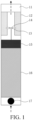
- FIG. 1 is a schematic diagram of an aerosol generation apparatus according to an embodiment of this application.
- the aerosol generation apparatus includes a suction nozzle 11, a liquid storage unit 12, a liquid transfer unit 13, a heating element 14, a circuit 15, a power supply 16, and a sensor 17.
- the suction nozzle 11 is configured for a user to inhale an aerosol generated by heating.
- the liquid storage unit 12 is configured to store a liquid for generating an aerosol.
- the liquid may be a liquid including tobacco substances containing volatile tobacco flavor components, or may be a liquid including non-tobacco substances.
- the liquid may include water, a solvent, ethanol, a plant extract, a spice, a fragrance, or a vitamin mixture.
- the spice may include menthol, peppermint, green mint oil, and various fruit flavor ingredients, but is not limited thereto.
- the fragrance may include ingredients that can provide a variety of smells or flavors to users.
- the vitamin mixture may be a substance mixed with at least one of vitamin A, vitamin B, vitamin C, and vitamin E, but is not limited thereto.
- the liquid may include an aerosol forming agent, such as glycerol and propylene glycol.
- the liquid transfer unit 13 can transfer the liquid stored in the liquid storage unit 12 to the heating element 14.
- the liquid transfer unit 13 may be cotton fiber, ceramic fiber, or glass fiber, but is not limited thereto.
- the heating element 14 is a component for heating the liquid transferred by the liquid transfer unit 13.
- the heating element 14 may be a metal wire, a metal plate, or a ceramic heater, but is not limited thereto.
- the heating element 14 may be composed of a conductive heating wire such as a nickel-chromium wire, and may be arranged into a structure wound on the liquid transfer unit 13. The heating element 14 may be heated by a current supply and transfer heat to the liquid in contact with the heating element 14 to heat the liquid, to generate the aerosol.
- the heating element 14 is made of a material with resistance temperature coefficient characteristics, such as: stainless steel 316, titanium, nickel, or nickel-chromium alloy.
- the circuit 15 can control the overall operation of the aerosol generation apparatus. Specifically, the circuit 15 not only controls the operation of the power supply 16 and the heating element 14, but also controls the operation of other elements in the aerosol generation apparatus. In addition, the circuit 15 can determine whether the aerosol generation apparatus is operable by checking the status of the components of the aerosol generation apparatus.
- the circuit 15 includes at least one processor.
- the processor may include a logic gate array, or may include a combination of a general-purpose microprocessor and a memory that stores an executable program in the microprocessor.
- a person skilled in the art should understand that the circuit 15 may include another type of hardware.
- the power supply 16 is configured to provide power for operating the aerosol generation apparatus.
- the power supply 16 can provide power to heat the heating element 14, and can provide power required for operating the circuit 15.
- the power supply 16 can provide power required for operating a sensor, a motor, and the like provided in the aerosol generation apparatus.
- the power supply 16 may be, but is not limited to, a lithium iron phosphate (LiFePO4) battery.
- the power supply 16 may be a lithium cobaltate (LiCoO2) battery or a lithium titanate battery.
- the power supply 16 may be a rechargeable battery or a disposable battery.
- the sensor 17 is configured to detect an inhalation action of a user and generate a corresponding electrical signal, so that the circuit 15 controls the operation of the power supply 16, the heating element 14, and the like according to the electrical signal.
- the sensor 17 may be a common pressure sensor, a differential pressure sensor, an airflow sensor, or the like.
- An air inlet hole is provided at a position at which the aerosol generation apparatus is close to the sensor 17.
- an airflow enters through the air inlet hole, flows through the sensor 17, the power supply 16, the circuit 15, the heating element 14, and the like, and then flows out through the suction nozzle 11.
- the dotted arrow in the figure roughly shows the airflow path.
- FIG. 1 merely shows components related to this embodiment.
- the aerosol generation apparatus may further include other general components besides those shown in FIG. 1 .
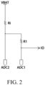
- FIG. 2 is a schematic diagram of a resistance detection circuit according to an embodiment of this application.
- Ri is the heating element 14, and R1 is a sampling resistor.
- the heating element 14 and the sampling resistor R1 are connected in series between the power supply 16 (shown by VBAT in the figure) and a push-pull output port IO of a processor.
- a first voltage sampling port ADC1 of the processor is connected at one end of the sampling resistor R1
- a second voltage sampling port ADC2 of the processor is connected at the other end of the sampling resistor R1.
- a switch tube connected in series with the sampling resistor R1 and an associated resistor thereof (with a larger resistance) are omitted.
- FIG. 3 is a schematic diagram of another resistance detection circuit according to an embodiment of this application.
- the circuit 15 includes a switch tube Q8, the heating element 14 (connected to ends D+ and D- in the figure), and a sampling resistor R4 connected in series successively between the positive and negative poles of the power supply 16 (shown by VBAT in the figure), and U1 is the sensor 17.
- a control end of the switch tube Q8 is connected to a control port OUT_CTR of the processor.
- the control port OUT_CTR can control connection or disconnection of the switch tube Q8.
- a first voltage sampling port AT-DET of the processor is arranged between the switch tube Q8 and the heating element 14, and a second voltage sampling port OUT1-ADC of the processor is arranged between the heating element 14 and the sampling resistor R4.
- the switch tube connected in series with the sampling resistor R1 and an associated resistor thereof are also omitted, and instead, a main circuit is used to detect the resistance.
- the circuit 15 is configured to determine whether the liquid stored in the liquid storage unit has decreased to a threshold after a corresponding preset time point when a resistance change rate of the heating element 14 decreases to the first resistance change rate during a period when the heating element 14 starts for heating.
- the value of the first resistance change rate herein is usually small, and is less than the resistance change rate of the heating element during the heating period just starting.
- the preset time point is determined according to a corresponding time when the resistance change rate of the heating element 14 decreases from a second resistance change rate of the heating element 14 at the initial startup of heating to the first resistance change rate, and the first resistance change rate is 1%-30% of the second resistance change rate.
- the second resistance change rate can be considered as the resistance change rate of the heating element 14 in a short period of time at the initial startup, and the resistance change rate in this period is usually large.
- whether the liquid stored in the liquid storage unit 12 has decreased to the threshold may be determined after the resistance change rate of the heating element decreases to 5% ⁇ 30% of the second resistance change rate; further preferably, whether the liquid stored in the liquid storage unit 12 has decreased to the threshold may be determined after the resistance change rate of the heating element decreases to 5% ⁇ 25% of the second resistance change rate; further preferably, whether the liquid stored in the liquid storage unit 12 has decreased to the threshold may be determined after the resistance change rate of the heating element decreases to 5% ⁇ 20% of the second resistance change rate; further preferably, whether the liquid stored in the liquid storage unit 12 has decreased to the threshold may be determined after the resistance change rate of the heating element decreases to 10% ⁇ 20% of the second resistance change rate.
- the preset time point is after the heating element starts for continuous heating for 600 ms (including 600 ms); preferably, the preset time point is after the heating element starts for continuous heating for 800 ms (including 800 ms); and further preferably, the preset time point is after the heating element starts for continuous heating for 1000 ms (including 1000 ms).
- the circuit 15 is configured to determine whether the liquid stored in the liquid storage unit 12 has decreased to the threshold according to amplitudes of the resistance change rate of the heating element 14 and a preset resistance change rate.
- the circuit 15 is further configured to control the power supply to stop outputting power to the heating element 14.
- the circuit 15 is configured to determine whether the liquid stored in the liquid storage unit 12 has decreased to the threshold according to a quantity of times that the resistance change rate of the heating element 14 continuously exceeds the preset resistance change rate.
- the circuit 15 is further configured to control the power supply to stop outputting power to the heating element 14.
- the circuit 15 is configured to determine whether the liquid stored in the liquid storage unit 12 has decreased to the threshold according to amplitudes of the real-time resistance of the heating element 14 and an over-temperature threshold.
- circuit 15 is configured to:
- the over-temperature threshold is a resistance corresponding to a maximum vaporization temperature acceptable by the aerosol generation apparatus during inhalation.
- the over-temperature threshold may be a default threshold or a dynamic threshold, which is determined according to different materials of the heating element 14.
- the preset temperature is a vaporization temperature that the aerosol generation apparatus is expected to maintain during inhalation to achieve the best vaporization effect.
- That the temperature of the heating element 14 has not been successfully maintained as the preset temperature or the real-time resistance of the heating element 14 has not been successfully maintained as the resistance corresponding to the preset temperature means that during the period when the power outputted to the heating element 14 decreases to the preset power, the real-time resistance or the temperature of the heating element 14 continues to rise. Specifically, the real-time resistance of the heating element 14 exceeds the resistance corresponding to the preset temperature, or the temperature of the heating element 14 exceeds the preset temperature.
- the temperature of the heating element 14 is generally excessively high due to continuous inhalation.
- the normal liquid supply still leads to the situation that the temperature of the heating element 14 has not been successfully maintained as the preset temperature, or the real-time resistance of the heating element 14 has not been successfully maintained as the resistance corresponding to the preset temperature.
- circuit 15 is configured to:
- N different values are set for identification.
- the N preset differences are empirical values or test values, for example, obtained by integrating test data through a large number of tests.
- N is a positive integer.
- N ranges from 8 to 16, preferably 8 to 14, and further preferably 8 to 12.
- a detection interval time of N real-time resistances ranges from 40 ms to 100 ms, preferably 40 ms to 80 ms.
- circuit 15 is configured to:
- whether the liquid stored in the liquid storage unit 12 has decreased to the threshold can also be determined by comparing the real-time resistance of the heating element 14 with the preset maximum threshold.
- the preset maximum threshold is greater than the above over-temperature threshold.
- FIG. 4 is a schematic diagram of a control process of an aerosol generation apparatus according to an embodiment of this application. The control process is described with specific cases, specifically including:
- a curve K1 is a curve during dry burning of the heating element 14 after the aerosol generation apparatus starts and before the aerosol generation apparatus is inhaled (for example, as shown by A in the figure)
- a curve K2 is a curve when no dry burning occurs in the heating element 14 after the aerosol generation apparatus starts and before the aerosol generation apparatus is inhaled.
- the ordinate in the figure is the resistance (milliohm) of the heating element 14, and the abscissa is the quantity of resistance detection times.
- a curve K3 is a curve of the heating element 14 when dry burning occurs when the aerosol generation apparatus is inhaled
- a curve K4 is a curve of the heating element 14 when dry burning does not occur when the aerosol generation apparatus is inhaled (dry burning occurs after the aerosol generation apparatus starts and before the aerosol generation apparatus is inhaled).
- the above determining method described in FIG. 6 is not suitable for the entire inhalation stage, such as the case shown in FIG. 5 . Since the resistance data fluctuates greatly during the period after the heating element 14 starts for heating to a specific time point (for example, a time point T1 in the figure), the above determining method can easily lead to inaccurate determining, which affects the inhalation experience of the user.
- the time point can be determined according to a time when the resistance change rate of the heating element 14 is reduced to 1% ⁇ 30% of the resistance change rate when the heating element 14 starts for heating.
- the time point T1 is used as an example for description.
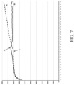
- a curve K5 is a curve during dry burning of the heating element 14 when the aerosol generation apparatus is inhaled
- a curve K6 is a curve when no dry burning occurs in the heating element 14 when the aerosol generation apparatus is inhaled.
- the real-time resistance of the heating element 14 can also be re-obtained and compared with the over-temperature threshold. If the real-time resistance of the heating element 14 exceeds the over-temperature threshold, the power outputted to the heating element 14 is reduced. When the temperature of the heating element 14 is successfully maintained as the preset temperature, it can be determined that dry burning occurs in the heating element 14 when the aerosol generation apparatus is inhaled. As shown in D in the figure, the real-time resistance of the heating element 14 at this node exceeds the over-temperature threshold. After reducing the power output to the heating element 14, the temperature of the heating element 14 is successfully maintained as the preset temperature.
- the real-time resistance of the heating element 14 at this node exceeds the over-temperature threshold.
- the temperature of the heating element 14 has not been successfully maintained as the preset temperature, and the resistance of the heating element 14 is still rising. Therefore, it can be determined that dry burning occurs in the heating element 14 when the aerosol generation apparatus is inhaled.
Landscapes
- Physics & Mathematics (AREA)
- Thermal Sciences (AREA)
- Fluid Mechanics (AREA)
- General Physics & Mathematics (AREA)
- Control Of Resistance Heating (AREA)
Applications Claiming Priority (2)
| Application Number | Priority Date | Filing Date | Title |
|---|---|---|---|
| CN202011160206.2A CN114468380B (zh) | 2020-10-27 | 2020-10-27 | 气溶胶生成装置 |
| PCT/CN2021/126447 WO2022089433A1 (fr) | 2020-10-27 | 2021-10-26 | Appareil de génération d'aérosol |
Publications (2)
| Publication Number | Publication Date |
|---|---|
| EP4238433A1 true EP4238433A1 (fr) | 2023-09-06 |
| EP4238433A4 EP4238433A4 (fr) | 2024-06-12 |
Family
ID=81381943
Family Applications (1)
| Application Number | Title | Priority Date | Filing Date |
|---|---|---|---|
| EP21885160.8A Pending EP4238433A4 (fr) | 2020-10-27 | 2021-10-26 | Appareil de génération d'aérosol |
Country Status (4)
| Country | Link |
|---|---|
| US (1) | US20240023627A1 (fr) |
| EP (1) | EP4238433A4 (fr) |
| CN (2) | CN120938166A (fr) |
| WO (1) | WO2022089433A1 (fr) |
Families Citing this family (3)
| Publication number | Priority date | Publication date | Assignee | Title |
|---|---|---|---|---|
| CN117491758A (zh) * | 2022-07-25 | 2024-02-02 | 深圳麦时科技有限公司 | 故障检测方法及其装置、可读存储介质和气溶胶雾化装置 |
| CN118203153A (zh) * | 2022-12-15 | 2024-06-18 | 深圳麦时科技有限公司 | 检测方法、检测装置、可读存储介质和气溶胶雾化装置 |
| CN118614654A (zh) * | 2023-03-10 | 2024-09-10 | 深圳市合元科技有限公司 | 电子雾化装置及其控制方法 |
Family Cites Families (11)
| Publication number | Priority date | Publication date | Assignee | Title |
|---|---|---|---|---|
| EP2468117A1 (fr) * | 2010-12-24 | 2012-06-27 | Philip Morris Products S.A. | Système de génération d'aérosol disposant de supports pour déterminer la déplétion d'un substrat liquide |
| CN107440157B (zh) * | 2017-08-15 | 2020-04-07 | 惠州市新泓威科技有限公司 | 电子烟的防干烧装置及其防干烧控制方法 |
| CN108851233B (zh) * | 2018-04-04 | 2020-02-28 | 赫斯提亚深圳生物科技有限公司 | 一种气溶胶生成装置及其控制方法 |
| JP7382347B2 (ja) * | 2018-05-30 | 2023-11-16 | フィリップ・モーリス・プロダクツ・ソシエテ・アノニム | 電気加熱式エアロゾル発生システムにおける有害なヒーター状態の検出 |
| JP6869436B2 (ja) * | 2018-06-22 | 2021-05-12 | 日本たばこ産業株式会社 | エアロゾル生成装置並びにこれを動作させる方法及びプログラム |
| KR20250102128A (ko) * | 2018-07-25 | 2025-07-04 | 필립모리스 프로덕츠 에스.에이. | 에어로졸 발생 시스템에서 가열을 제어하는 방법 |
| CN111134371B (zh) * | 2018-11-02 | 2022-05-17 | 常州市派腾电子技术服务有限公司 | 电子烟控制方法、电子烟及计算机存储介质 |
| CN109588785B (zh) * | 2019-01-21 | 2023-12-19 | 深圳市太美亚电子科技有限公司 | 一种电子烟的防干烧控制电路 |
| CN110558617B (zh) * | 2019-07-30 | 2022-12-27 | 深圳麦克韦尔科技有限公司 | 电子雾化装置、加热控制方法、装置和存储介质 |
| CN110487848A (zh) * | 2019-07-30 | 2019-11-22 | 深圳麦克韦尔科技有限公司 | 雾化组件含油量检测方法、装置及电子雾化装置 |
| CN111000294B (zh) * | 2019-12-17 | 2022-07-08 | 深圳麦克韦尔科技有限公司 | 雾化器的加热方法、装置、计算机设备和存储介质 |
-
2020
- 2020-10-27 CN CN202511298700.8A patent/CN120938166A/zh active Pending
- 2020-10-27 CN CN202011160206.2A patent/CN114468380B/zh active Active
-
2021
- 2021-10-26 US US18/034,358 patent/US20240023627A1/en active Pending
- 2021-10-26 EP EP21885160.8A patent/EP4238433A4/fr active Pending
- 2021-10-26 WO PCT/CN2021/126447 patent/WO2022089433A1/fr not_active Ceased
Also Published As
| Publication number | Publication date |
|---|---|
| CN114468380A (zh) | 2022-05-13 |
| WO2022089433A1 (fr) | 2022-05-05 |
| EP4238433A4 (fr) | 2024-06-12 |
| CN120938166A (zh) | 2025-11-14 |
| CN114468380B (zh) | 2025-09-09 |
| US20240023627A1 (en) | 2024-01-25 |
Similar Documents
| Publication | Publication Date | Title |
|---|---|---|
| EP4238433A1 (fr) | Appareil de génération d'aérosol | |
| US20230301366A1 (en) | E-cigarette and control method thereof | |
| DK2896104T3 (en) | Portable electronic system including charging device and method for charging a secondary battery | |
| US20230240379A1 (en) | Inhalation component generating device, control circuit, and control method and control program of inhalation component generating device | |
| RU2735592C1 (ru) | Устройство, генерирующее компонент для вдыхания, способ управления устройством, генерирующим компонент для вдыхания, и компьютерно-читаемый носитель данных | |
| KR102203851B1 (ko) | 에어로졸 생성 장치 및 이를 제어하는 방법 | |
| US11271481B2 (en) | Inhalation component generating device, control circuit, and control method and control program of inhalation component generating device | |
| CN107105774B (zh) | 用于电子吸烟设备的动态输出电源管理 | |
| EA039494B1 (ru) | Устройство, генерирующее компонент для вдыхания, способ управления устройством, генерирующим компонент для вдыхания, и программа | |
| KR20190035486A (ko) | 에어로졸 생성장치의 피드백 제어기능을 구현하는 방법 및 그 에어로졸 생성장치 | |
| EA039450B1 (ru) | Устройство, генерирующее компонент для вдыхания, способ управления устройством, генерирующим компонент для вдыхания, система, генерирующая компонент для вдыхания, и программа | |
| US20250185724A1 (en) | Electronic atomization apparatus and control method for electronic atomization apparatus | |
| WO2025157026A1 (fr) | Dispositif de génération d'aérosol et son procédé de commande | |
| US20230126544A1 (en) | Method for determining at least one parameter for the vaporization in an inhaler, and an inhaler | |
| EP4678037A1 (fr) | Appareil d'atomisation électronique et son procédé de commande | |
| JP7510996B2 (ja) | 吸引成分生成装置、吸引成分生成装置を制御する方法、及びプログラム | |
| CN222941814U (zh) | 气溶胶生成装置 | |
| CN120660920A (zh) | 气溶胶生成装置及其控制方法 | |
| WO2026012262A1 (fr) | Dispositif de génération d'aérosol et son procédé de commande | |
| CN121445117A (zh) | 气溶胶生成装置及其控制方法 | |
| CN120827223A (zh) | 气溶胶生成装置 | |
| WO2025025973A1 (fr) | Procédé de mesure du nombre de bouffées et dispositif de génération d'aérosol | |
| CN121286790A (zh) | 气溶胶生成装置及其方法 | |
| HK40026437B (zh) | 吸气组分生成设备、控制电路、控制方法 | |
| HK1246512B (en) | Portable electronic system including charging device and method of charging a secondary battery |
Legal Events
| Date | Code | Title | Description |
|---|---|---|---|
| STAA | Information on the status of an ep patent application or granted ep patent |
Free format text: STATUS: THE INTERNATIONAL PUBLICATION HAS BEEN MADE |
|
| PUAI | Public reference made under article 153(3) epc to a published international application that has entered the european phase |
Free format text: ORIGINAL CODE: 0009012 |
|
| STAA | Information on the status of an ep patent application or granted ep patent |
Free format text: STATUS: REQUEST FOR EXAMINATION WAS MADE |
|
| 17P | Request for examination filed |
Effective date: 20230512 |
|
| AK | Designated contracting states |
Kind code of ref document: A1 Designated state(s): AL AT BE BG CH CY CZ DE DK EE ES FI FR GB GR HR HU IE IS IT LI LT LU LV MC MK MT NL NO PL PT RO RS SE SI SK SM TR |
|
| DAV | Request for validation of the european patent (deleted) | ||
| DAX | Request for extension of the european patent (deleted) | ||
| REG | Reference to a national code |
Ref country code: DE Ref legal event code: R079 Free format text: PREVIOUS MAIN CLASS: A24F0040460000 Ipc: A24F0040530000 |
|
| STAA | Information on the status of an ep patent application or granted ep patent |
Free format text: STATUS: EXAMINATION IS IN PROGRESS |
|
| A4 | Supplementary search report drawn up and despatched |
Effective date: 20240513 |
|
| RIC1 | Information provided on ipc code assigned before grant |
Ipc: A24F 40/10 20200101ALI20240506BHEP Ipc: A24F 40/53 20200101AFI20240506BHEP |
|
| 17Q | First examination report despatched |
Effective date: 20240524 |