EP4238683B1 - Schnellwechselvorrichtung und -verfahren für den schweisskopf einer ultraschall-metallschweissmaschine - Google Patents
Schnellwechselvorrichtung und -verfahren für den schweisskopf einer ultraschall-metallschweissmaschine Download PDFInfo
- Publication number
- EP4238683B1 EP4238683B1 EP23157843.6A EP23157843A EP4238683B1 EP 4238683 B1 EP4238683 B1 EP 4238683B1 EP 23157843 A EP23157843 A EP 23157843A EP 4238683 B1 EP4238683 B1 EP 4238683B1
- Authority
- EP
- European Patent Office
- Prior art keywords
- mounting plate
- welding head
- fixing
- block
- quick
- Prior art date
- Legal status (The legal status is an assumption and is not a legal conclusion. Google has not performed a legal analysis and makes no representation as to the accuracy of the status listed.)
- Active
Links
Images



Classifications
-
- B—PERFORMING OPERATIONS; TRANSPORTING
- B23—MACHINE TOOLS; METAL-WORKING NOT OTHERWISE PROVIDED FOR
- B23K—SOLDERING OR UNSOLDERING; WELDING; CLADDING OR PLATING BY SOLDERING OR WELDING; CUTTING BY APPLYING HEAT LOCALLY, e.g. FLAME CUTTING; WORKING BY LASER BEAM
- B23K20/00—Non-electric welding by applying impact or other pressure, with or without the application of heat, e.g. cladding or plating
- B23K20/10—Non-electric welding by applying impact or other pressure, with or without the application of heat, e.g. cladding or plating making use of vibrations, e.g. ultrasonic welding
-
- B—PERFORMING OPERATIONS; TRANSPORTING
- B23—MACHINE TOOLS; METAL-WORKING NOT OTHERWISE PROVIDED FOR
- B23K—SOLDERING OR UNSOLDERING; WELDING; CLADDING OR PLATING BY SOLDERING OR WELDING; CUTTING BY APPLYING HEAT LOCALLY, e.g. FLAME CUTTING; WORKING BY LASER BEAM
- B23K20/00—Non-electric welding by applying impact or other pressure, with or without the application of heat, e.g. cladding or plating
- B23K20/10—Non-electric welding by applying impact or other pressure, with or without the application of heat, e.g. cladding or plating making use of vibrations, e.g. ultrasonic welding
- B23K20/106—Features related to sonotrodes
-
- B—PERFORMING OPERATIONS; TRANSPORTING
- B23—MACHINE TOOLS; METAL-WORKING NOT OTHERWISE PROVIDED FOR
- B23K—SOLDERING OR UNSOLDERING; WELDING; CLADDING OR PLATING BY SOLDERING OR WELDING; CUTTING BY APPLYING HEAT LOCALLY, e.g. FLAME CUTTING; WORKING BY LASER BEAM
- B23K20/00—Non-electric welding by applying impact or other pressure, with or without the application of heat, e.g. cladding or plating
- B23K20/26—Auxiliary equipment
Definitions
- the present application relates to the technical field of ultrasonic metal welding, and more particularly to a quick-replace device and method for welding head of ultrasonic metal welding machine.
- the ultrasonic metal welding machine is generally consisted of a framework, an ultrasonic generator and an ultrasonic triplet.
- the ultrasonic triplet includes a transducer, an amplitude modulator and a welding head.
- the framework drives the welding head to move to the workpiece to be welded.
- the ultrasonic triplet converts the electric energy generated by the ultrasonic generator with a certain frequency into the mechanical energy of the same frequency and outputs it through the welding head.
- High-frequency mechanical vibration is transferred from the welding head to the surface of the workpiece, which causes the friction of the surface of the workpiece to form fusion between the molecular layers, so as to weld the workpiece.
- ultrasonic welding has the characteristics of fast welding speed, high welding strength, good sealing, low cost, clean and pollution-free, so it is widely used.
- a triple-group mounting seat fixing device of an ultrasonic welding machine comprises a welding machine body and a triplet group mounting seat, the welding machine body is provided with a guide groove extending along the linear direction, the end face of the guide groove is provided with an opening, and the triplet group mounting seat is inserted into the guide groove from the opening.
- a guide groove is formed in the middle of the three-group mounting base, a guide arm extending towards the direction of the three-group mounting base is arranged on the groove wall of the guide groove, convex blocks are arranged on the two sides of the three-group mounting base, a side face pressing block is arranged in the guide groove, and an operation piece used for pushing the side face pressing block to press the three-group mounting base is arranged on the guide groove.
- a quick-replace device for the welding head of the ultrasonic metal welding machine includes a fixing mechanism for fixedly connecting a framework and a movable mechanism for fixing an ultrasonic triplet including a transducer, an amplitude modulator and a welding head, the movable mechanism being detachably mounted in the fixing mechanism, and including a mounting plate and a connecting assembly for fixing the ultrasonic triplet, the connecting assembly being arranged on the mounting plate;
- the fixing mechanism including a fixing block for a fixed connection to the framework, a mounting groove being defined in the fixing block with at least one side thereof being open and extending in use in a direction perpendicular to the framework, the mounting plate being slidably mounted in the mounting groove, and an abutting block for fixing the mounting plate being mounted in the fixing block.
- a positioning block is detachably mounted on the fixing block in a direction perpendicular to the sliding direction of the mounting plate and abuts against the mounting plate in a direction perpendicular to the adjusting direction of the
- the mounting plate is slidably mounted into the mounting groove.
- the position limiting bars at two sides of the mounting plate are in the first limiting groove and second limiting groove, respectively.
- the cooperation of the position limiting bars with the first and second limiting grooves on the one hand realizes the support of the mounting groove to the mounting plate, and on the other hand realizes the guiding function to the mounting plate, facilitating the sliding installation of the mounting plate.
- the guiding block on the abutting block slides in the guiding groove to guide and limit the sliding direction of the abutting block, making the sliding of the abutting block more stable.
- a positioning block is detachably mounted on the fixing block and abuts against the mounting plate in a direction perpendicular to the adjusting direction of the abutting block.
- the positioning block is mounted on the fixing block after the mounting plate is assembled.
- the positioning block is pressed against the mounting plate and cooperates with the framework to limit the sliding direction of the mounting plate, so as to further fix the mounting plate.
- the positioning block needs to be removed firstly.
- a position plate for facilitating positioning of the welding head during assembly of the welding head is provided on the mounting plate.
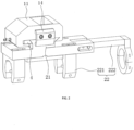
- the welding head holding device is consisted of two separate parts, i.e., the fixing mechanism 1 and the movable mechanism 2, only the movable mechanism 2 needs to be disassembled and assembled for replacing the welding head 26, which reduces the overall weight of the part to be replaced and makes the replacement of the welding head 26 more labor-saving.
- the fixing mechanism 1 includes a fixing block 11, which is fixedly mounted onto the side wall of the framework 23.
- the fixing block 11 defines a mounting groove 3 which extends along a direction perpendicular to the framework 23. Both ends of the mounting groove 3 are open, and one of the open ends of the mounting groove 3 close to the framework 23 abuts against the framework 23.
- the movable mechanism 2 includes a mounting plate 21 and a connecting assembly 22.
- the mounting plate 21 is slidably mounted into the mounting groove 3 along the direction perpendicular to framework 23.
- the connecting assembly 22 is used to fix the ultrasonic triplet, and is fixedly mounted at an end of the mounting plate 21 away from the fixing block 11.
- An abutting block 4 is slidably mounted into the fixing block 11 along a direction perpendicular to the sliding direction of the mounting plate 21, and abuts against the mounting plate 21.
- a positioning block 14 which is generally C-shaped is detachably mounted to a side wall of the fixing block 11 away from the framework 23 by bolts. One end face of the positioning block 14 abuts against the fixing block 11, and the other end face of the positioning block 14 abuts against the mounting plate 21.
- the abutting block 4 cooperates with the mounting groove 3 to fix the mounting plate 21 in a direction perpendicular to the sliding direction of the mounting plate 21, and the positioning block 14 cooperates with the framework 23 to fix the mounting plate 21 in the sliding direction of the mounting plate 21.
- Two guiding grooves 12 are defined in the fixing block 11 along the sliding direction of the block 4, two guiding blocks 13 are fixedly mounted to a side wall of the block 4 close to the guide grooves 12 by bolts, and the guiding blocks 13 are slidably engaged into the guide grooves 12 along the sliding direction of the abutting block 4.
- the adjusting member 9 is rotated to drive the abutting block 4 to move.
- the guiding blocks 13 cooperate with the guide grooves 12 to make the movement of the abutting block 4 more stable.
- the fastener 10 is rotated to fix the adjusting member 9 to make the abutting block 4 be fixed more stable.
- two side walls of the mounting plate 21 are respectively provided with a position limiting bar 5 at an end thereof close to the fixing block 11.
- the position limiting bar 5 is fixed to the sidewall, and extends along the sliding direction of the mounting plate 21.
- a cross section of the position limiting bar 5 is generally triangular-shaped, and a width of the cross section gradually increases from bottom to top.
- a first limiting groove 6 is defined in an end of the fixing block 11 away from the abutting block 4, and communicates with the mounting groove 3.
- a chamfer 7 is formed on the abutting block 4, which cooperates with a bottom wall of the mounting groove 3 to form a second limiting groove 8.
- Cross sections of the first limiting groove 6 and second limiting groove 8 are the same as the cross section of the position limiting bar 5, and an adjustment range of the abutting block 4 is less than the maximum width of the cross section of the position limiting bar 5.
- the two position limiting bars 5 are slidably mounted into the first limiting groove 6 and second limiting groove 8 along the sliding direction of the mounting plate 21, respectively.
- the mounting groove 3 provides a support to the mounting plate 21, which makes the mounting plate 21 not easy to have a safety risk of falling of the ultrasonic triplet during the disassembly of the welding head 26 by the workers, and thus a single worker can disassemble the welding head 26 by himself.
- the steps of assembly of the welding head 26 are opposite to the above steps, and a single worker can also assemble the welding head 26 by himself. Therefore, the replacement of the welding head 26 is time-saving and labor-saving, and is more convenient and fast.
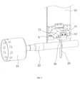
- the connection assembly 22 includes two clamping jaws 221 and a clamping member 222, wherein the clamping jaws 221 are used to fixedly clamp the welding head 26, and the clamping member 222 is used to fixedly clamp the amplitude modulator 25.
- Four sliding grooves 32 are defined in the mounting plate 21 and extend along the axial direction of the ultrasonic triplet.
- the two clamping jaws 221 are fixed to a side wall of the mounting plate 21 away from the fixing block 11 by bolts.
- the bolts are slidably mounted in the sliding grooves 32, and the two clamping jaws 221 are provided with threaded holes. When the clamping jaws 221 clamp the welding head 26, the bolts extend through the threaded holes to fix the welding head 26.
- the clamping member 222 is mounted to a side wall of the mounting plate 21, and is capable of being adjusted along the axis direction of the ultrasonic triplet.
- the clamping member 222 includes a connecting rod 2221 and a hose clamp 2222.
- a position limiting groove 19 is defined in the mounting plate 21, and the connecting rod 2221 slides into the position limiting groove 19 of the mounting plate 21 along the axis direction of the ultrasonic triplet.
- the hose clamp 2222 is fixed to an end of the connecting rod 2221 away from the mounting plate 21 by bolts, and is perpendicular to the connecting rod 2221 for fixing the amplitude modulator 25.
- a plurality of second mounting holes 29 are defined in the connecting rod 2221 and evenly spaced from each other along the sliding direction of the connecting rod 2221.
- Three first mounting holes 28 are defined in the mounting plate 21 and evenly spaced from each other, and communicate with the position limiting groove 19.
- a fixture 18 is screwed in the first mounting hole 28 of the mounting plate 21. The fixture 18 extends through the first mounting hole 28 and then threads in the second mounting hole 29.
- Two fixtures 18 are provided and mounted in the first mounting holes 28 at two ends of the connecting rod 2221 in the sliding direction of the connecting rod 2221, respectively. In this application, the fixtures 18 may be bolts. After the connecting rod 2221 slides to adjust positions, it is fixed by the fixtures 18. By means of the two fixtures 18 which are arranged at two ends of the connecting rod 2221 in the sliding direction, the fixing effect of the fixtures 18 is improved.
- a position plate 15 is detachably connected to a side wall of the mounting plate 21 far away from the fixing block 11 by bolts and located between the two clamping jaws 221.
- a width of the position plate 15 is about one half of that of the mounting plate 21, and a latching slot 27 is defined in a side wall of the position plate 15 which is close to a middle of the mounting plate 21 in the width direction.
- the welding head 26 abuts a side wall of the mounting plate 21 close to the position plate 15 and is engaged in the latching slot 27.
- a position limiting slot 16 is defined in a side wall of the mounting plate 21 close to the position plate 15 and extends along the width direction of the mounting plate 21.
- a position limiting bar 17 is provided on a side wall of the position plate 15 close to the mounting plate 21 and extends along the width direction of the position plate 15.
- the position limiting bar 17 is slidably engaged into the position limiting slot 16.
- the bolts are rotated to fix the clamping jaws 221, and at the same time, the welding head 26 in the clamping jaw 221 is fixed by the bolts .
- the position plate 15 is removed. By means of using the position plate 15 to pre-position the welding head 26, the positioning of the welding head 26 is more convenient and accurate during installation. At the same time, using the position plate 15 enables the workers with different work experience to assemble the welding head 26 accurately, thereby reducing the assembly difficulty of the welding head 26.
- the implementation principle of the second embodiment is as follows: during assembly of the welding head 26, the mounting plate 21 slides into the mounting groove 3 of the fixing block 11 to make the position limiting bar 5 slide into the first limit guide groove 6 and second limit guide groove 8, the adjusting member 9 is then rotated to drive the abutting block 4 to move to fix the mounting plate 21, the fastener 10 is then rotated to fix the adjusting member 9, and finally the positioning block 14 is fixed to the fixing block 11 by bolts to complete the assembly of the welding head 26.
- the welding head 26 can be disassembled by reverse operation according to the above steps.
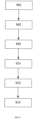
- the ultrasonic triplet is mounted to the mounting plate 21, and then the mounting plate 21 slides into the fixing block 11 from the open side of the mounting groove 3.
- the mounting groove 3 of the fixing block 11 supports the mounting plate 21, and then the abutting block 4 is used to fix the mounting plate 21, thus assembly of the welding head 26 is completed.
- the whole assembly process can be completed by a single worker, and it can effectively avoid the safety risk of falling of the ultrasonic triplet.
- the method further comprises disassembling a welding head 26 to be replaced before step S11, and disassembling the welding head 26 to be replaced comprises the following steps:
- the abutting block 4 is adjusted to release the fixed state with the mounting plate 21.
- the mounting groove 3 of the fixing block 11 supports the mounting plate 21, and the ultrasonic triplet is not prone to the safety risk of falling, and then the mounting plate 21 slides out of the mounting groove 3 to complete the disassembly of the welding head 26.
- the whole disassembly process can be completed by a single worker, and it can effectively avoid the safety risk of falling of the ultrasonic triplet.
- the method further comprises: providing a positioning block 14 and connecting the positioning block 14 to the open side of the mounting groove 3 of the fixing block 11 after step S13, so as to limit the movement of the mounting plate 21 along the fourth direction; and removing the positioning block 14 which is connected to the open side of the mounting groove 3 of the fixing block 11 before step S01.
- the positioning block 14 is mounted onto the fixing block 11 to limit the sliding of the mounting plate 21 after the assembly of the mounting plate 21 is finished, so as to further fix the mounting plate 21. Similarly, during disassembly of the mounting plate 21, it is necessary to remove the positioning block 14 firstly.
- the step S11 comprises: providing a position plate 15 with a latching slot 27 and connecting the position plate 15 to the mounting plate 21 detachably; docking the welding head 26 to be assembled with the latching slot 27 for positioning, so that the welding head 26 is perpendicular to the mounting plate 21; clamping the welding head 26 through the connecting assembly 22 and moving relative to the mounting plate 21 until the connecting assembly 22 contacts with the position plate 15; fixing the connecting assembly 22 to the mounting plate 21; and removing the position plate 15 from the mounting plate 21.
- the position plate 15 is mounted onto the mounting plate 21 for positing the welding head 26, making the positioning of the welding head 26 more convenient and accurate during installation.
Landscapes
- Engineering & Computer Science (AREA)
- Mechanical Engineering (AREA)
- Pressure Welding/Diffusion-Bonding (AREA)
- Lining Or Joining Of Plastics Or The Like (AREA)
Claims (13)
- Eine Schnellwechselvorrichtung für einen Schweißkopf einer Ultraschallmetallschweißmaschine, wobeidie Schnellwechselvorrichtung umfasst:einen Befestigungsmechanismus (1) für eine feste Verbindung an einen Rahmen undeinen bewegbaren Mechanismus (2) zum Befestigen eines Ultraschall-Tripletts, wobei das Ultraschall-Triplett einen Wandler, einen Amplitudenschallgeber und einen Schweißkopf umfasst,der bewegliche Mechanismus (2) lösbar in dem Befestigungsmechanismus (1) montiert ist, und eine Montageplatte (21) und eine Verbindungsbaugruppe (22) zum Befestigen des Ultraschall-Tripletts umfasst, wobei die Verbindungsbaugruppe (22) auf der Montageplatte (21) angeordnet ist;der Befestigungsmechanismus (1) einen Befestigungsblock (11) für die feste Verbindung an dem Rahmen umfasst,ein Anschlagblock (4) zum Befestigen der Montageplatte (21) in dem Befestigungsblock (11) montiert ist, undein Positionierblock (14) der lösbar auf dem Befestigungsblock (11) in einer Richtung senkrecht zu einer Gleitrichtung der Montageplatte (21) montiert ist und an der Montageplatte (21) in einer Richtung senkrecht zu der Verstellrichtung des Anschlagblocks (4) anschlägt, dadurch gekennzeichnet, dassder Befestigungsmechanismus (1) eine Montagenut (3) umfasst, die in dem Befestigungsblock (11) definiert ist, wobei mindestens eine Seite davon offen ist und sich bei Verwendung in einer Richtung senkrecht zu dem Rahmen erstreckt, wobei die Montageplatte (21) gleitbar in der Montagenut (3) montiert ist.
- Die Schnellwechselvorrichtung für einen Schweißkopf einer Ultraschallmetallschweißmaschine gemäß Anspruch 1, wobei
zwei Seiten der Montageplatte (21) entlang ihrer Gleitrichtung mit zwei positionseinschränkenden Balken (5) versehen sind, eine erste einschränkende Nut (6), die mit der Montagenut (3) in Verbindung steht, in dem ersten Befestigungsblock (11) definiert ist, eine Fase (7) an einem Ende des Anschlagblocks (4) nahe der Montageplatte (21) ausgebildet ist und mit einem Boden der Montagenut (3) zusammenwirkt, um eine zweite eingrenzende Nut (8) auszubilden, und die zwei positionseinschränkenden Balken (5) sind gleitbar in der ersten einschränkenden Nut (6) bzw. der zweiten einschränkenden Nut (8) entlang der Gleitrichtung der Montageplatte (21) montiert. - Die Schnellwechselvorrichtung für einen Schweißkopf einer Ultraschallmetallschweißmaschine gemäß Anspruch 1, wobei
ein Ende des Anschlagblocks (4) entfernt von der Montageplatte (21) mit einem Verstellteil (9) zum Anpassen einer Position des Anschlagblocks (4) versehen ist, und die Befestigung des Verstellteils (9) ist mit einem Befestigungselement (10) versehen, um sich selbst zu befestigen. - Die Schnellwechselvorrichtung für einen Schweißkopf einer Ultraschallmetallschweißmaschine gemäß Anspruch 1, wobei
eine Führungsnut (12) in dem Befestigungsblock (11) definiert ist, ein Führungsblock (13) an dem Anschlagblock (4) bereitgestellt ist, und der Führungsblock (13) zu der Führungsnut (12) passt und gleitbar in der Führungsnut (12) entlang einer Verstellrichtung des Anschlagblocks (4) montiert ist. - Die Schnellwechselvorrichtung für einen Schweißkopf einer Ultraschallmetallschweißmaschine gemäß Anspruch 1, wobei
die Verbindungsbaugruppe (22) eine Spannbacke (221) zum Befestigen des Schweißkopfes und ein Spannteil (222) zum Befestigen des Amplitudenschallgebers umfasst, und das Spannteil (222) ist auf der Montageplatte (21) montiert und entlang einer Achsenrichtung des Ultraschall-Tripletts verstellbar. - Die Schnellwechselvorrichtung für einen Schweißkopf einer Ultraschallmetallschweißmaschine gemäß Anspruch 5, wobei
das Spannteil (222) eine Verbindungsstange (2221) und eine Schlauchklemme (2222) umfasst, die Verbindungsstange (2221) gleitbar auf der Montageplatte (21) entlang der Achsenrichtung des Ultraschall-Tripletts montiert ist, die Schlauchklemme (2222) an einem Ende der Verbindungsstange (2221) entfernt von der Montageplatte (21) zum Befestigen des Amplitudenschallgebers montiert ist, und eine Befestigung (18) zum Befestigen der Verbindungsstange (2221) an der Montageplatte (21) montiert ist. - Die Schnellwechselvorrichtung für einen Schweißkopf einer Ultraschallmetallschweißmaschine gemäß Anspruch 6, wobei
eine positionseinschränkende Nut (19) in der Montageplatte (21) entlang einer Gleitrichtung der Verbindungsstange (2221) definiert ist und die Verbindungsstange (2221) passt zu und ist gleitbar in der positionseinschränkenden Nut (19) montiert. - Die Schnellwechselvorrichtung für einen Schweißkopf einer Ultraschallmetallschweißmaschine gemäß Anspruch 1, wobei
eine Positionierplatte (15) zum Vereinfachen des Positionierens des Schweißkopfes während des Zusammenbaus des Schweißkopfes an der Montageplatte (21) bereitgestellt ist. - Die Schnellwechselvorrichtung eines Schweißkopfes einer Ultraschallmetallschweißmaschine gemäß Anspruch 8, wobei
ein positionseinschränkender Schlitz (16) in einer Seitenwand der Montageplatte (21) nahe der Positionierplatte (15) definiert ist, und ein positionseinschränkender Balken (17) ist an einer Seitenwand der Positionierplatte (15) nahe der Montageplatte (21) bereitgestellt, und der positionseinschränkende Balken (17) passt zu und ist aufgenommen in dem positionseinschränkenden Schlitz (16). - Ein Schnellwechselverfahren für einen Schweißkopf einer Ultraschallmetallschweißmaschine, dadurch gekennzeichnet, dass das Verfahren von einer Schnellwechselvorrichtung für den Schweißkopf der Ultraschallmetallschweißmaschine gemäß einem der Ansprüche 1-9 durchgeführt wird, und das Schnellwechselverfahren umfasst die folgenden Schritte:S11, Verbinden eine zusammenzubauenden Schweißkopfes (26) mit der Montageplatte (21) des bewegbaren Mechanismus (2)S12, Montieren der Montageplatte (21) in der Montagenut (3) des Befestigungsblocks (11) des Befestigungsmechanismus (1) entlang einer ersten Richtung;S13, Bewegen des Anschlagblocks (4) entlang einer zweiten Richtung, um die Montageplatte (21) in der Montagenut (3) zu befestigen, wobei die zweite Richtung und die erste Richtung miteinander einen Winkel bilden, wobei das Verfahren weiterhin umfasst:Bereitstellen eines Positionierblocks (14) und Verbinden des Positionierblocks (14) mit der offenen Seite der Montagenut (3) des Befestigungsblocks (11) nach Schritt S13, um die Bewegung der Montageplatte (21) entlang der vierten Richtung einzuschränken; undEntfernen des Positionierblocks (14), der mit der offenen Seite der Montagenut (3) des Befestigungsblocks (11) verbunden ist, vor Schritt S01.
- Das Schnellwechselverfahren gemäß Anspruch 10, wobei das Verfahren des Weiteren umfasst: Auseinanderbauen eines zu ersetzenden Schweißkopfes (26) vor Schritt S11, was die folgenden Schritte umfasst:S01, Bewegen des Anschlagblocks (4) entlang einer dritten Richtung, um die Montageplatte (21) zu lockern, die in der Montagenut (3) durch den Anschlagblock (4) befestigt ist, wobei die dritte Richtung entgegengesetzt zu der zweiten Richtung ist;S02, Entnehmen der Montageplatte (21) aus der Montagenut (3) entlang einer vierten Richtung, wobei die vierte Richtung entgegengesetzt zu der ersten Richtung ist;S03, Entfernen des zu ersetzenden Schweißkopfes (26) von der Montageplatte (21), mit der er verbunden ist.
- Das Schnellwechselverfahren gemäß Anspruch 10, wobei der Schritt S11 umfasst:Bereitstellen einer Positionierplatte (15) mit einem Verriegelungsschlitz (27) und lösbares Verbinden der Positionierplatte (15) mit der Montageplatte (21);Andocken des zusammenzubauenden Schweißkopfes (26) an den Verriegelungsschlitz (27) zum Positionieren, sodass der Schweißkopf (26) senkrecht zu der Montageplatte (21) ist;Klemmen des Schweißkopfes (26) durch die Verbindungsbaugruppe (22) und relatives Bewegen zu der Montageplatte (21), bis die Verbindungsbaugruppe (22) die Positionierplatte (15) berührt;Befestigen der Verbindungsbaugruppe (22) an die Montageplatte (21); undEntfernen der Positionierplatte (15) von der Montageplatte (21).
- Das Schnellwechselverfahren gemäß Anspruch 10, wobei die erste Richtung und die zweite Richtung senkrecht zueinander sind, und Kontaktoberflächen des Anschlagblocks (4) und der Montageplatte (21) sind in einem bestimmen Winkel bezogen auf die erste Richtung und die zweite Richtung geneigt.
Applications Claiming Priority (1)
| Application Number | Priority Date | Filing Date | Title |
|---|---|---|---|
| CN202210160112.8A CN114589391B (zh) | 2022-02-22 | 2022-02-22 | 一种超声波金属焊机焊头快换装置 |
Publications (3)
| Publication Number | Publication Date |
|---|---|
| EP4238683A1 EP4238683A1 (de) | 2023-09-06 |
| EP4238683B1 true EP4238683B1 (de) | 2025-04-09 |
| EP4238683C0 EP4238683C0 (de) | 2025-04-09 |
Family
ID=81806316
Family Applications (1)
| Application Number | Title | Priority Date | Filing Date |
|---|---|---|---|
| EP23157843.6A Active EP4238683B1 (de) | 2022-02-22 | 2023-02-21 | Schnellwechselvorrichtung und -verfahren für den schweisskopf einer ultraschall-metallschweissmaschine |
Country Status (2)
| Country | Link |
|---|---|
| EP (1) | EP4238683B1 (de) |
| CN (1) | CN114589391B (de) |
Families Citing this family (5)
| Publication number | Priority date | Publication date | Assignee | Title |
|---|---|---|---|---|
| CN116532778B (zh) * | 2023-04-24 | 2023-11-07 | 东莞市索莱德自动化科技有限公司 | 一种超声波滚焊设备 |
| CN117532886B (zh) * | 2023-12-01 | 2024-11-12 | 江苏驰耐特防腐科技有限公司 | 一种防腐储罐内衬焊接四氟的装置 |
| CN117733344B (zh) * | 2024-02-21 | 2024-05-10 | 山西建投装备制造有限公司 | 一种施工升降机标准节自动焊接设备及方法 |
| CN117921272B (zh) * | 2024-03-22 | 2024-06-21 | 安徽鸿昊钢结构彩板有限公司 | 一种活动板房轻钢结构、组装焊接方法及装置 |
| CN119927495B (zh) * | 2025-04-08 | 2025-06-20 | 山西瑞铭科技有限公司 | 一种混凝土电杆钢筋骨架焊接成型装置 |
Citations (3)
| Publication number | Priority date | Publication date | Assignee | Title |
|---|---|---|---|---|
| CN211165374U (zh) | 2019-10-31 | 2020-08-04 | 无锡邦能超声科技有限公司 | 一种超声波焊接机的焊接装置抱紧机构 |
| CN213135413U (zh) | 2020-09-04 | 2021-05-07 | 深圳市深发源精密科技有限公司 | 一种超声波焊接机的施焊机构 |
| CN214602498U (zh) | 2021-03-02 | 2021-11-05 | 上海幸义超声技术有限公司 | 一种超声波焊机的三联组安装座固定装置 |
Family Cites Families (6)
| Publication number | Priority date | Publication date | Assignee | Title |
|---|---|---|---|---|
| US9545751B2 (en) * | 2010-10-26 | 2017-01-17 | Rinco Ultrasonics USA, Inc. | Pedestal-mounted ultrasonic welding device |
| JP5737562B2 (ja) * | 2011-02-09 | 2015-06-17 | 株式会社アドウェルズ | 共振器の支持装置 |
| CN207494778U (zh) * | 2017-11-15 | 2018-06-15 | 东莞新能源科技有限公司 | 焊接装置 |
| JP7214991B2 (ja) * | 2018-06-28 | 2023-01-31 | Tdk株式会社 | 超音波接合ヘッド、超音波接合装置および超音波接合方法 |
| CN211276959U (zh) * | 2020-05-25 | 2020-08-18 | 常青智能科技(天津)有限公司 | 一种快换式超声波焊接装置 |
| CN217551420U (zh) * | 2022-02-22 | 2022-10-11 | 必能信超声(上海)有限公司 | 一种超声波金属焊机焊头快换装置 |
-
2022
- 2022-02-22 CN CN202210160112.8A patent/CN114589391B/zh active Active
-
2023
- 2023-02-21 EP EP23157843.6A patent/EP4238683B1/de active Active
Patent Citations (3)
| Publication number | Priority date | Publication date | Assignee | Title |
|---|---|---|---|---|
| CN211165374U (zh) | 2019-10-31 | 2020-08-04 | 无锡邦能超声科技有限公司 | 一种超声波焊接机的焊接装置抱紧机构 |
| CN213135413U (zh) | 2020-09-04 | 2021-05-07 | 深圳市深发源精密科技有限公司 | 一种超声波焊接机的施焊机构 |
| CN214602498U (zh) | 2021-03-02 | 2021-11-05 | 上海幸义超声技术有限公司 | 一种超声波焊机的三联组安装座固定装置 |
Also Published As
| Publication number | Publication date |
|---|---|
| EP4238683C0 (de) | 2025-04-09 |
| CN114589391B (zh) | 2025-09-26 |
| CN114589391A (zh) | 2022-06-07 |
| EP4238683A1 (de) | 2023-09-06 |
Similar Documents
| Publication | Publication Date | Title |
|---|---|---|
| EP4238683A1 (de) | Schnellwechselvorrichtung und -verfahren für den schweisskopfe einer ultraschall-metallschweissmaschine | |
| KR200499458Y1 (ko) | 초음파 금속 용접기의 용접 헤드 신속 교체 장치 | |
| CN1590010A (zh) | 管子夹持组件 | |
| KR101767345B1 (ko) | 다양한 반지름을 갖는 곡선 금속판 제작용 용접 지그 및 이를 이용한 용접 방법 | |
| CN117259818B (zh) | 一种传动轴叉类零件镗孔装置 | |
| CN116100335B (zh) | 一种工件加工辅助夹持工装 | |
| CN219562246U (zh) | 一种工装夹具 | |
| CN112318021A (zh) | 一种焊接定位工装夹具 | |
| CN218904389U (zh) | 一种异形薄板件端面加工夹具 | |
| CN219004634U (zh) | 一种机床楔式定心涨紧机床工装夹具 | |
| CN215281007U (zh) | 一种异形零件的半自动液压工装 | |
| CN212191807U (zh) | 一种带有定位装置的焊接机器人 | |
| CN209936389U (zh) | 一种自动调整臂壳体的加工装置 | |
| CN220295876U (zh) | 一种机器人夹具 | |
| CN224196303U (zh) | 一种铆压结构 | |
| CN222768181U (zh) | 一种定位工装 | |
| CN223603465U (zh) | 一种可快速更换的车床卡盘 | |
| CN222289912U (zh) | 一种高效安装加工设备的夹具 | |
| CN222971400U (zh) | 自定心滚花装置 | |
| CN217912911U (zh) | 一种机床卡爪装置 | |
| CN221247242U (zh) | 一种滑块沟槽线切割加工夹具 | |
| CN224209887U (zh) | 一种轴承辅助拆装设备 | |
| CN221211459U (zh) | 工装夹具 | |
| CN114346566B (zh) | 一种焊接夹具及焊接设备 | |
| CN219837479U (zh) | 一种用于医疗器械的多点式机加工夹具 |
Legal Events
| Date | Code | Title | Description |
|---|---|---|---|
| PUAI | Public reference made under article 153(3) epc to a published international application that has entered the european phase |
Free format text: ORIGINAL CODE: 0009012 |
|
| STAA | Information on the status of an ep patent application or granted ep patent |
Free format text: STATUS: THE APPLICATION HAS BEEN PUBLISHED |
|
| AK | Designated contracting states |
Kind code of ref document: A1 Designated state(s): AL AT BE BG CH CY CZ DE DK EE ES FI FR GB GR HR HU IE IS IT LI LT LU LV MC ME MK MT NL NO PL PT RO RS SE SI SK SM TR |
|
| STAA | Information on the status of an ep patent application or granted ep patent |
Free format text: STATUS: REQUEST FOR EXAMINATION WAS MADE |
|
| 17P | Request for examination filed |
Effective date: 20231010 |
|
| RBV | Designated contracting states (corrected) |
Designated state(s): AL AT BE BG CH CY CZ DE DK EE ES FI FR GB GR HR HU IE IS IT LI LT LU LV MC ME MK MT NL NO PL PT RO RS SE SI SK SM TR |
|
| STAA | Information on the status of an ep patent application or granted ep patent |
Free format text: STATUS: EXAMINATION IS IN PROGRESS |
|
| 17Q | First examination report despatched |
Effective date: 20240124 |
|
| GRAP | Despatch of communication of intention to grant a patent |
Free format text: ORIGINAL CODE: EPIDOSNIGR1 |
|
| STAA | Information on the status of an ep patent application or granted ep patent |
Free format text: STATUS: GRANT OF PATENT IS INTENDED |
|
| INTG | Intention to grant announced |
Effective date: 20240816 |
|
| GRAJ | Information related to disapproval of communication of intention to grant by the applicant or resumption of examination proceedings by the epo deleted |
Free format text: ORIGINAL CODE: EPIDOSDIGR1 |
|
| STAA | Information on the status of an ep patent application or granted ep patent |
Free format text: STATUS: EXAMINATION IS IN PROGRESS |
|
| GRAP | Despatch of communication of intention to grant a patent |
Free format text: ORIGINAL CODE: EPIDOSNIGR1 |
|
| STAA | Information on the status of an ep patent application or granted ep patent |
Free format text: STATUS: GRANT OF PATENT IS INTENDED |
|
| INTC | Intention to grant announced (deleted) | ||
| INTG | Intention to grant announced |
Effective date: 20241206 |
|
| GRAS | Grant fee paid |
Free format text: ORIGINAL CODE: EPIDOSNIGR3 |
|
| GRAA | (expected) grant |
Free format text: ORIGINAL CODE: 0009210 |
|
| STAA | Information on the status of an ep patent application or granted ep patent |
Free format text: STATUS: THE PATENT HAS BEEN GRANTED |
|
| AK | Designated contracting states |
Kind code of ref document: B1 Designated state(s): AL AT BE BG CH CY CZ DE DK EE ES FI FR GB GR HR HU IE IS IT LI LT LU LV MC ME MK MT NL NO PL PT RO RS SE SI SK SM TR |
|
| REG | Reference to a national code |
Ref country code: GB Ref legal event code: FG4D |
|
| REG | Reference to a national code |
Ref country code: CH Ref legal event code: EP |
|
| REG | Reference to a national code |
Ref country code: DE Ref legal event code: R096 Ref document number: 602023002773 Country of ref document: DE |
|
| REG | Reference to a national code |
Ref country code: IE Ref legal event code: FG4D |
|
| U01 | Request for unitary effect filed |
Effective date: 20250507 |
|
| U07 | Unitary effect registered |
Designated state(s): AT BE BG DE DK EE FI FR IT LT LU LV MT NL PT RO SE SI Effective date: 20250513 |
|
| PG25 | Lapsed in a contracting state [announced via postgrant information from national office to epo] |
Ref country code: ES Free format text: LAPSE BECAUSE OF FAILURE TO SUBMIT A TRANSLATION OF THE DESCRIPTION OR TO PAY THE FEE WITHIN THE PRESCRIBED TIME-LIMIT Effective date: 20250409 |
|
| PG25 | Lapsed in a contracting state [announced via postgrant information from national office to epo] |
Ref country code: NO Free format text: LAPSE BECAUSE OF FAILURE TO SUBMIT A TRANSLATION OF THE DESCRIPTION OR TO PAY THE FEE WITHIN THE PRESCRIBED TIME-LIMIT Effective date: 20250709 Ref country code: GR Free format text: LAPSE BECAUSE OF FAILURE TO SUBMIT A TRANSLATION OF THE DESCRIPTION OR TO PAY THE FEE WITHIN THE PRESCRIBED TIME-LIMIT Effective date: 20250710 |
|
| PG25 | Lapsed in a contracting state [announced via postgrant information from national office to epo] |
Ref country code: PL Free format text: LAPSE BECAUSE OF FAILURE TO SUBMIT A TRANSLATION OF THE DESCRIPTION OR TO PAY THE FEE WITHIN THE PRESCRIBED TIME-LIMIT Effective date: 20250409 |
|
| PG25 | Lapsed in a contracting state [announced via postgrant information from national office to epo] |
Ref country code: HR Free format text: LAPSE BECAUSE OF FAILURE TO SUBMIT A TRANSLATION OF THE DESCRIPTION OR TO PAY THE FEE WITHIN THE PRESCRIBED TIME-LIMIT Effective date: 20250409 |
|
| PG25 | Lapsed in a contracting state [announced via postgrant information from national office to epo] |
Ref country code: RS Free format text: LAPSE BECAUSE OF FAILURE TO SUBMIT A TRANSLATION OF THE DESCRIPTION OR TO PAY THE FEE WITHIN THE PRESCRIBED TIME-LIMIT Effective date: 20250709 |
|
| PG25 | Lapsed in a contracting state [announced via postgrant information from national office to epo] |
Ref country code: IS Free format text: LAPSE BECAUSE OF FAILURE TO SUBMIT A TRANSLATION OF THE DESCRIPTION OR TO PAY THE FEE WITHIN THE PRESCRIBED TIME-LIMIT Effective date: 20250809 |
|
| PG25 | Lapsed in a contracting state [announced via postgrant information from national office to epo] |
Ref country code: SM Free format text: LAPSE BECAUSE OF FAILURE TO SUBMIT A TRANSLATION OF THE DESCRIPTION OR TO PAY THE FEE WITHIN THE PRESCRIBED TIME-LIMIT Effective date: 20250409 |
|
| PLBI | Opposition filed |
Free format text: ORIGINAL CODE: 0009260 |
|
| PG25 | Lapsed in a contracting state [announced via postgrant information from national office to epo] |
Ref country code: CZ Free format text: LAPSE BECAUSE OF FAILURE TO SUBMIT A TRANSLATION OF THE DESCRIPTION OR TO PAY THE FEE WITHIN THE PRESCRIBED TIME-LIMIT Effective date: 20250409 |
|
| REG | Reference to a national code |
Ref country code: CH Ref legal event code: L10 Free format text: ST27 STATUS EVENT CODE: U-0-0-L10-L00 (AS PROVIDED BY THE NATIONAL OFFICE) Effective date: 20260121 |
|
| PG25 | Lapsed in a contracting state [announced via postgrant information from national office to epo] |
Ref country code: SK Free format text: LAPSE BECAUSE OF FAILURE TO SUBMIT A TRANSLATION OF THE DESCRIPTION OR TO PAY THE FEE WITHIN THE PRESCRIBED TIME-LIMIT Effective date: 20250409 |
|
| 26 | Opposition filed |
Opponent name: HERRMANN ULTRASCHALLTECHNIK GMBH & CO. KG Effective date: 20260109 |
|
| PLAX | Notice of opposition and request to file observation + time limit sent |
Free format text: ORIGINAL CODE: EPIDOSNOBS2 |
|
| U20 | Renewal fee for the european patent with unitary effect paid |
Year of fee payment: 4 Effective date: 20260226 |