EP4238689A1 - Appareil de marquage et procédé de marquage - Google Patents
Appareil de marquage et procédé de marquage Download PDFInfo
- Publication number
- EP4238689A1 EP4238689A1 EP22160156.0A EP22160156A EP4238689A1 EP 4238689 A1 EP4238689 A1 EP 4238689A1 EP 22160156 A EP22160156 A EP 22160156A EP 4238689 A1 EP4238689 A1 EP 4238689A1
- Authority
- EP
- European Patent Office
- Prior art keywords
- laser beam
- solid material
- vegetable fibers
- mark
- controller
- Prior art date
- Legal status (The legal status is an assumption and is not a legal conclusion. Google has not performed a legal analysis and makes no representation as to the accuracy of the status listed.)
- Granted
Links
Images



Classifications
-
- B—PERFORMING OPERATIONS; TRANSPORTING
- B23—MACHINE TOOLS; METAL-WORKING NOT OTHERWISE PROVIDED FOR
- B23K—SOLDERING OR UNSOLDERING; WELDING; CLADDING OR PLATING BY SOLDERING OR WELDING; CUTTING BY APPLYING HEAT LOCALLY, e.g. FLAME CUTTING; WORKING BY LASER BEAM
- B23K26/00—Working by laser beam, e.g. welding, cutting or boring
- B23K26/34—Laser welding for purposes other than joining
-
- B—PERFORMING OPERATIONS; TRANSPORTING
- B23—MACHINE TOOLS; METAL-WORKING NOT OTHERWISE PROVIDED FOR
- B23K—SOLDERING OR UNSOLDERING; WELDING; CLADDING OR PLATING BY SOLDERING OR WELDING; CUTTING BY APPLYING HEAT LOCALLY, e.g. FLAME CUTTING; WORKING BY LASER BEAM
- B23K26/00—Working by laser beam, e.g. welding, cutting or boring
- B23K26/352—Working by laser beam, e.g. welding, cutting or boring for surface treatment
-
- B—PERFORMING OPERATIONS; TRANSPORTING
- B23—MACHINE TOOLS; METAL-WORKING NOT OTHERWISE PROVIDED FOR
- B23K—SOLDERING OR UNSOLDERING; WELDING; CLADDING OR PLATING BY SOLDERING OR WELDING; CUTTING BY APPLYING HEAT LOCALLY, e.g. FLAME CUTTING; WORKING BY LASER BEAM
- B23K26/00—Working by laser beam, e.g. welding, cutting or boring
- B23K26/02—Positioning or observing the workpiece, e.g. with respect to the point of impact; Aligning, aiming or focusing the laser beam
- B23K26/06—Shaping the laser beam, e.g. by masks or multi-focusing
- B23K26/062—Shaping the laser beam, e.g. by masks or multi-focusing by direct control of the laser beam
- B23K26/0626—Energy control of the laser beam
-
- B—PERFORMING OPERATIONS; TRANSPORTING
- B23—MACHINE TOOLS; METAL-WORKING NOT OTHERWISE PROVIDED FOR
- B23K—SOLDERING OR UNSOLDERING; WELDING; CLADDING OR PLATING BY SOLDERING OR WELDING; CUTTING BY APPLYING HEAT LOCALLY, e.g. FLAME CUTTING; WORKING BY LASER BEAM
- B23K26/00—Working by laser beam, e.g. welding, cutting or boring
- B23K26/02—Positioning or observing the workpiece, e.g. with respect to the point of impact; Aligning, aiming or focusing the laser beam
- B23K26/06—Shaping the laser beam, e.g. by masks or multi-focusing
- B23K26/064—Shaping the laser beam, e.g. by masks or multi-focusing by means of optical elements, e.g. lenses, mirrors or prisms
-
- B—PERFORMING OPERATIONS; TRANSPORTING
- B23—MACHINE TOOLS; METAL-WORKING NOT OTHERWISE PROVIDED FOR
- B23K—SOLDERING OR UNSOLDERING; WELDING; CLADDING OR PLATING BY SOLDERING OR WELDING; CUTTING BY APPLYING HEAT LOCALLY, e.g. FLAME CUTTING; WORKING BY LASER BEAM
- B23K26/00—Working by laser beam, e.g. welding, cutting or boring
- B23K26/08—Devices involving relative movement between laser beam and workpiece
- B23K26/082—Scanning systems, i.e. devices involving movement of the laser beam relative to the laser head
-
- B—PERFORMING OPERATIONS; TRANSPORTING
- B23—MACHINE TOOLS; METAL-WORKING NOT OTHERWISE PROVIDED FOR
- B23K—SOLDERING OR UNSOLDERING; WELDING; CLADDING OR PLATING BY SOLDERING OR WELDING; CUTTING BY APPLYING HEAT LOCALLY, e.g. FLAME CUTTING; WORKING BY LASER BEAM
- B23K26/00—Working by laser beam, e.g. welding, cutting or boring
- B23K26/352—Working by laser beam, e.g. welding, cutting or boring for surface treatment
- B23K26/355—Texturing
-
- B—PERFORMING OPERATIONS; TRANSPORTING
- B41—PRINTING; LINING MACHINES; TYPEWRITERS; STAMPS
- B41J—TYPEWRITERS; SELECTIVE PRINTING MECHANISMS, i.e. MECHANISMS PRINTING OTHERWISE THAN FROM A FORME; CORRECTION OF TYPOGRAPHICAL ERRORS
- B41J2/00—Typewriters or selective printing mechanisms characterised by the printing or marking process for which they are designed
- B41J2/435—Typewriters or selective printing mechanisms characterised by the printing or marking process for which they are designed characterised by selective application of radiation to a printing material or impression-transfer material
- B41J2/475—Typewriters or selective printing mechanisms characterised by the printing or marking process for which they are designed characterised by selective application of radiation to a printing material or impression-transfer material for heating selectively by radiation or ultrasonic waves
- B41J2/4753—Typewriters or selective printing mechanisms characterised by the printing or marking process for which they are designed characterised by selective application of radiation to a printing material or impression-transfer material for heating selectively by radiation or ultrasonic waves using thermosensitive substrates, e.g. paper
-
- B—PERFORMING OPERATIONS; TRANSPORTING
- B23—MACHINE TOOLS; METAL-WORKING NOT OTHERWISE PROVIDED FOR
- B23K—SOLDERING OR UNSOLDERING; WELDING; CLADDING OR PLATING BY SOLDERING OR WELDING; CUTTING BY APPLYING HEAT LOCALLY, e.g. FLAME CUTTING; WORKING BY LASER BEAM
- B23K2103/00—Materials to be soldered, welded or cut
- B23K2103/30—Organic materials
-
- B—PERFORMING OPERATIONS; TRANSPORTING
- B23—MACHINE TOOLS; METAL-WORKING NOT OTHERWISE PROVIDED FOR
- B23K—SOLDERING OR UNSOLDERING; WELDING; CLADDING OR PLATING BY SOLDERING OR WELDING; CUTTING BY APPLYING HEAT LOCALLY, e.g. FLAME CUTTING; WORKING BY LASER BEAM
- B23K2103/00—Materials to be soldered, welded or cut
- B23K2103/30—Organic materials
- B23K2103/36—Wood or similar materials
-
- B—PERFORMING OPERATIONS; TRANSPORTING
- B23—MACHINE TOOLS; METAL-WORKING NOT OTHERWISE PROVIDED FOR
- B23K—SOLDERING OR UNSOLDERING; WELDING; CLADDING OR PLATING BY SOLDERING OR WELDING; CUTTING BY APPLYING HEAT LOCALLY, e.g. FLAME CUTTING; WORKING BY LASER BEAM
- B23K2103/00—Materials to be soldered, welded or cut
- B23K2103/30—Organic materials
- B23K2103/38—Fabrics; Fibrous materials
-
- B—PERFORMING OPERATIONS; TRANSPORTING
- B23—MACHINE TOOLS; METAL-WORKING NOT OTHERWISE PROVIDED FOR
- B23K—SOLDERING OR UNSOLDERING; WELDING; CLADDING OR PLATING BY SOLDERING OR WELDING; CUTTING BY APPLYING HEAT LOCALLY, e.g. FLAME CUTTING; WORKING BY LASER BEAM
- B23K2103/00—Materials to be soldered, welded or cut
- B23K2103/30—Organic materials
- B23K2103/40—Paper
-
- B—PERFORMING OPERATIONS; TRANSPORTING
- B41—PRINTING; LINING MACHINES; TYPEWRITERS; STAMPS
- B41J—TYPEWRITERS; SELECTIVE PRINTING MECHANISMS, i.e. MECHANISMS PRINTING OTHERWISE THAN FROM A FORME; CORRECTION OF TYPOGRAPHICAL ERRORS
- B41J2/00—Typewriters or selective printing mechanisms characterised by the printing or marking process for which they are designed
- B41J2/435—Typewriters or selective printing mechanisms characterised by the printing or marking process for which they are designed characterised by selective application of radiation to a printing material or impression-transfer material
- B41J2/44—Typewriters or selective printing mechanisms characterised by the printing or marking process for which they are designed characterised by selective application of radiation to a printing material or impression-transfer material using single radiation source per colour, e.g. lighting beams or shutter arrangements
- B41J2/442—Typewriters or selective printing mechanisms characterised by the printing or marking process for which they are designed characterised by selective application of radiation to a printing material or impression-transfer material using single radiation source per colour, e.g. lighting beams or shutter arrangements using lasers
Definitions
- the invention relates to a marking apparatus and a marking method.
- a carbon dioxide laser can be used to make dark markings such as data matrices and barcodes on cardboard.
- dark markings such as data matrices and barcodes
- care should be taken because a right amount of optical power should be delivered to the cardboard in order to avoid burning but still ensuring a clearly readable marks.
- this kind of careful marking to the surface of cardboard requires several process stages. Additionally, the present marking possibilities do not respond properly to the desired variety of the markings.
- the present invention seeks to provide an improvement in the markings.
- Figures illustrate various embodiments, they are simplified diagrams that only show some structures and/or functional entities.
- the connections shown in the Figures may refer to logical or physical connections. It is apparent to a person skilled in the art that the described apparatus may also comprise other functions and structures than those described in Figures and text. It should be appreciated that details of some functions, structures, and the signalling used for measurement and/or controlling are irrelevant to the actual invention. Therefore, they need not be discussed in more detail here.
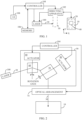
- Fig. 1 illustrates an example of a marking apparatus.
- the marking apparatus comprises at least one carbon dioxide laser 100, which output a laser beam 30, and at least one laser beam directing apparatus 102, which directs the laser beam 30 to a marking area 20. From this on the at least one laser beam directing apparatus 102 is called the laser beam directing apparatus 102, for simplicity.
- the marking area 20 is for a solid material 10 of vegetable fibers with natural hue.
- the solid material 10 of vegetable fibers may be cardboard or paper which is unbleached or only partially bleached having more or less the natural hue.
- a representation 40 of at least one mark of the one or more marks information on which is in one or more memories 108, can be formed, in the following manner, on the solid material 10 of vegetable fibers.
- the representation 40 is an image of the at least one mark.
- At least one controller 104 receives information on the at least one mark from the one or more memories 108. From this on the at least one controller 104 is called the controller 104, for simplicity. Then the controller 104 controls the laser beam directing apparatus 102 and/or the at least one carbon dioxide laser 100 based on the information on the at least one mark to perform a selection of an energy-per-unit-area range from a first energy range and a second energy range. The selection may vary as a function of time during a single process stage from start to finish. The first energy range and the second energy range may be predetermined ranges, which are known because they depend on the material of the solid material 10 of vegetable fibers. The selection is based on the at least one mark each requiring at least one energy-per-unit-area range.
- Energy of the laser beam 30 per surface area of the solid material of the vegetable fibers 10 may be based on control parameters of the laser 100 and/or the laser beam directing apparatus 102 such as travelling speed of the laser beam 30, power and frequency of pulsation of the laser 100 (the laser may also output the optical radiation continuously). Energy of the laser beam 30 per surface area of the solid material of the vegetable fibers 10 may be based on hatching distance and their angle with respect to representation 40 or a sub-feature of the representation 40.
- the first energy range for the laser beam 30 causes the solid material 10 of vegetable fibers to become visibly darker than the natural hue in response to interaction with the laser beam 30 and the second energy range causes the solid material 10 of vegetable fibers to become visibly lighter than the natural hue in response to interaction with the laser beam 30. That is, the change to visibly darker or lighter hue takes place at an area hit by the laser beam 30 and it is caused by the laser beam 30.
- the change to visibly darker can be considered to mean that a ratio of the visible light reflected from the solid material 10 of vegetable fibers with respect to the visible light directed to it becomes lower.
- the change to visibly lighter can be considered to mean that a ratio of the visible light reflected from the solid material 10 of vegetable fibers with respect to the visible light directed to it becomes higher. It can be considered that brightness of the surface of the solid material of vegetable fibers 10 changes.
- the laser beam directing apparatus 102 causes the laser beam 30 to travel over the solid material 10 of vegetable fibers in response to the control by the controller 104.
- the travelling of the laser beam 30 is based on the at least one mark for forming the representation 40 of said at least one mark on a surface of the solid material 10 of vegetable fibers with the selected at least one energy-per-unit-area range in the single process stage from start to finish.
- a process cycle can be defined as a single process phase or stage that completes a single manufacturing operation, from start to finish, meaning that a product passes through the single stage of its production.
- the single stage of production includes formation of visible marks on the solid material 10 made of vegetable fibers of natural hue.
- the single process stage can be understood to mean that once the program, which causes the at least one desired mark that is to be transferred to the solid material of vegetable fibers 10, is triggered to start, it continues without a break till the end of the program and all of the at least one desired mark is replicated on the solid material of vegetable fibers 10 in a continuous manner.
- the natural hue may mean that a part of the fibers, which means less than all fibers, have been partially or fully bleached while another part of the fibers have not been bleached at all and they have the full natural hue.
- That the representation 40 is visible means that the representation 40 is seen with a naked eye of a human being in illumination of visible light.
- the visible light means one or more optical bands of electromagnetic radiation within a range from about 400 nm to about 750 nm.
- the wavelength of the carbon dioxide laser 100 may be about 10 600 nm ⁇ about 2 000 nm.
- the controller 104 may control the wavelength of the laser 100 with respect to the natural hue and/or composition of the solid material 10 of vegetable fibers. Additionally or alternatively, the controller 104 may control the wavelength of the laser 100 with respect to at least one mark that is to be transferred on a surface of the solid material 10 of vegetable fibers.
- the laser beam 30 may be made to travel over the solid material 10 of vegetable fibers by moving the laser 100 with respect to the solid material 10 of vegetable fibers.
- the laser 100 may be moved by an actuator, which may comprise electric, pneumatic or hydraulic motors, for example.
- the laser beam 30 may be made to travel over the solid material 10 of vegetable fibers by moving the solid material 10 of vegetable fibers with respect to the laser 100.
- the solid material 10 of vegetable fibers may be moved by an actuator, which may comprise electric, pneumatic or hydraulic mover(s)/motor(s), conveyor belt, for example.
- the actuator may be a roll-to-roll system. A person skilled in the art is familiar with these kinds of movement arrangements, per se.
- the laser beam directing apparatus 104 may comprise at least one laser beam deflector 50. From this on the at least one laser beam deflector 50 is called the laser beam deflector 50, for simplicity.
- the carbon dioxide laser 100 may direct the laser beam 30 to the laser beam deflector 50, which deflects the laser beam 30 to a marking area 20 which is meant to have the solid material 10 of vegetable fibers with natural hue for forming the representation 40 of the at least one mark of the one or more marks thereon.
- the laser beam deflector 50 may comprise a first direction reflector 60 and a second direction reflector 70 which may rotate by turning with respect to their rotation axes.
- the first direction X and the second direction Y may be orthogonal and they can be parallel to unit vectors of a Cartesian coordinate system.
- the reflectors 60 and 70 may comprise silicon, molybdenum, nickel copper alloy (NiCu), aluminum and/or copper mirrors, for example, without limiting to these.
- the reflectors 60, 70 may covered with gold or silver, for example.
- the first direction reflector 60 receives the laser beam 30 and deflects it in the first direction toward the second direction reflector 60 that then deflects the laser beam 30 in the second direction and directs the laser beam 30 toward the marking area 20 where the solid material 10 of vegetable fibers is.
- the first and second reflector 60, 70 rotate round their rotational axes 80 and 90 they cause the laser beam 30 to travel over the solid material 10 of the vegetable fibers according to and following a geometrical shape defined the at least one mark, the geometrical shape resulting in the representation 40 on the solid material 10 of the vegetable fibers.
- the laser beam deflector 50 may comprise an acousto-optic modulator and/or magneto-optic modulator for making the laser beam 30 to travel on the surface of the solid material of vegetable fibers 10 in order to replicate the at least one mark as the representation to the surface.
- the mark comprises information on one or more graphical patterns, one or more alphanumerical signs and/or writing symbols of the representation 40.
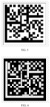
- Figs 3, 4 and 5 examples of representations 40 of a data matrix are presented.
- Figs 3, 4 , 5, 6 , 7 and 8 the natural hue is shown with hatched lines, white area is bleached visibly lighter than that of the natural hue by the laser beam 30, and the black area is made visibly darker than that of the natural hue by the laser beam 30.
- the controller 104 may control the carbon dioxide laser 100 and/or the laser beam directing apparatus 102 to direct the laser beam 30 within an energy range about 0.5 J/cm 2 and about 30 J/cm 2 , without limiting to these values.
- the energy range may refer to a fixed energy range or an average energy range.
- the energy of the laser beam 30 at the surface of the solid material 10 of vegetable fibers depends in general on both a travelling speed of the laser beam 30 caused by the laser beam directing apparatus 102 and the optical power of the laser beam 30. Additionally, the energy range or values may depend on the type or quality of the solid material 10 of the vegetable fibers.
- only the second energy range which causes the solid material 10 of vegetable fibers to become visibly lighter than the natural hue, may be selected for forming the representation 40 defined by a combination of areas, where one area has the natural hue and another area is visibly lighter than the natural hue.
- the background 300 which is at least the size of the one or more graphical patterns, one or more alphanumerical signs and/or writing symbols of the representation 40, has been made visibly lighter that the natural hue, and the graphical data matrix 302 is presented with the natural hue on the background 300. That is, the laser beam 30 has interacted with the solid material 10 of the vegetable fibers only in the area of the background 300.
- the laser beam 30 has been directed to only an area of the one or more graphical patterns, one or more alphanumerical signs and/or writing symbols of the representation 40, which is a data matrix in Fig. 8 .
- the controller 104 may control the carbon dioxide laser 100 and/or the laser beam directing apparatus 104 to direct the laser beam 30 of the second energy range within an energy range about 0.5 J/cm 2 and about 4.5 J/cm 2 , without limiting to these values, in order to cause the solid material 10 of the vegetable fibers to become visibly lighter than the natural hue of the solid material 10 of the vegetable fibers (see Figs. 3 , 5 , 7 and 8 ).
- the energy range may refer to a fixed energy range or an average energy range. Additionally, the energy range or values may depend on the type or quality of the solid material 10 of the vegetable fibers.
- the controller 104 is configured to select only the first energy range for forming the representation 40 defined by a combination of areas, one having the natural hue and another being visibly darker than the natural hue.
- the laser beam 30 has been directed to only an area of the one or more graphical patterns, one or more alphanumerical signs and/or writing symbols of the representation 40, which is a data matrix in Fig. 4 .
- the laser beam 30 has been directed to only an area of the background of the representation 40, and the area of the one or more graphical patterns, one or more alphanumerical signs and/or writing symbols of the representation 40 is left to have the natural hue. That is, the data matrix has the natural hue in Fig. 6 .
- the controller 104 may control the carbon dioxide laser 100 and/or the laser beam directing apparatus 102 to direct a laser beam of the first energy range within an energy range about 4.5 J/cm 2 and about 30 J/cm 2 , without limiting to these values, in order to cause the solid material 10 of the vegetable fibers to become darker than the natural hue of the solid material 10 of the vegetable fibers (see Figs. 4 , 5 , 6 and 7 ).
- the energy range may refer to a fixed energy range or an average energy range. Additionally, the energy range or values may depend on the type or quality of the solid material 10 of the vegetable fibers.
- the solid material 10 of vegetable fibers may move and the laser beam directing apparatus 102 may cause the laser beam 30 to travel over the moving solid material 10 of vegetable fibers in response to the control by the controller 104 based on the at least one mark and information on the movement of the solid material 10 of vegetable fibers. That is, the marking of the solid material 10 of vegetable fibers may be performed on the fly.
- the solid material 10 of vegetable fibers may move at a constant speed and the controller 104 may have the information of the constant speed which enables the controller 104 to regulate the speed of the laser beam 30 suitably with respect to the speed of the solid material 10 of vegetable fibers.
- the controller 104 may control also the speed of the solid material 10 of vegetable fibers and the speed of the solid material 10 of vegetable fibers may be constant or variable. As the information of the speed of the solid material 10 of vegetable fibers is available to the controller 104, it may regulate the speed of the laser beam 30 suitably with respect to the speed of the solid material 10 of vegetable fibers. In this manner, it is possible to move the laser beam at a desired or constant speed with respect to the solid material 10 of vegetable fibers in any direction on the surface of the solid material 10 of vegetable fibers. That means that the movement of the laser beam with respect to the solid material 10 of vegetable fibers can be kept the same in a direction parallel to the movement of the solid material 10 of vegetable fibers and in the direction vertical to it and in any direction therebetween. A person skilled in the art is familiar with this kind of speed control, per se.
- the controller 104 may receive the information on the speed of the solid material 10 of vegetable fibers from an external source, and based on the received information the controller 104 may regulate the speed of the laser beam 30 suitably with respect to the speed of the solid material 10 of vegetable fibers.
- the controller 104 may regulate the speed of the laser beam 30 suitably with respect to the speed of the solid material 10 of vegetable fibers.
- the controller 104 may set the first and/or second energy range for the laser beam 30 based on the properties and/or composition of the solid material 10 of vegetable fibers, for example.
- the controller 104 may also increase or decrease energy of the first and/or second energy ranges. Properties may be, for example, natural hue and/or humidity of the solid material 10 of vegetable fibers without limiting to these.
- the energy range may refer to a fixed energy range or an average energy range.
- the marking apparatus comprises at least one optical arrangement 74 for forming the laser beam 30. From this on the at least one optical arrangement 74 is called the optical arrangement 74, for simplicity.
- the carbon dioxide laser 100 comprises the optical arrangement 74.
- the optical arrangement 74 is related to the resonator cavity of the carbon dioxide laser 100.
- the at least one optical arrangement 74 of the marking apparatus may have additional and separate optical components for manipulating the laser beam 30.
- the solid material 10 of vegetable fibers may move and the laser beam directing apparatus 102 may receive information on the moving solid material 10 of vegetable fibers.
- the controller 104 may control, in response to the information on the movement of the solid material 10 of vegetable fibers, the carbon dioxide laser 100 to output the laser beam 30 with suitable energy-per-unit-area range. That is, the marking of the solid material 10 of vegetable fibers may be performed on the fly.
- the solid material 10 of vegetable fibers may move at a constant speed and the controller 104 may have the information of the constant speed which enables the controller 104 to regulate the carbon dioxide laser 100. In this manner, the laser beam 30 does not need to be optically deflected although it may also be deflected.
- the controller 104 may control at least one optical arrangement 74 which comprises at least one optical component of the optical arrangement that may cause divergence and/or convergence.
- the at least one optical component may comprise at least one lens that forms a real image and/or at least one lens that forms a virtual image.
- the diameter of the laser beam 30 may be altered by one of the presented manner or by a combination of the presented manners.
- the marking apparatus may comprise a user interface 108, and the controller 104 may present information on advancement of the formation of the representation 40 on the surface of the solid material 10 of vegetable fibers.
- a representation may be divided into a plurality of sub-features which may be letters of alphabets or writing character such as kanji-signs, hiragana signs, katakana-signs, Arab, Korean, (Indian) devanagari, Burmese writing symbols, or numbers, any of their combination or the like, for example.
- the sub-features may be geometrical figures such as lines, curves or polygons, any of their combination or the like, for example.
- the monitoring of the advancement may be based on a comparison how many of the sub-features have already been formed and how many still needs to be formed on the surface of the surface of the solid material 10 of vegetable fibers.
- the monitoring of the advancement may be based on time used for formation of a representation.
- the controller 104 may have predetermined information on a duration how long it takes to transfer a sub-feature or a whole representation to the surface of the surface of the solid material 10 of vegetable fibers.
- the controller 104 may monitor the time used for the formation of the representation.
- the percentage of used time for the formation or the representation with respect to the predetermined information may be a suitable measure of the advancement.
- the controller 104 comprises one or more processors 900.
- the one or more memories 106 includes a computer program code.
- the one or more memories 106 and the computer program code may, with the one or more processors 900, cause the controller 104 to control the laser beam directing apparatus 102 and/or the carbon dioxide laser 100 to perform the selection of the energy-per-unit-area range from the first energy range and the second energy range based on the at least one mark.
- the one or more memories 106 and the computer program code may, with the one or more processors 900, cause the controller 104 to cause the laser beam directing apparatus 102 to cause the laser beam 30 to travel over the solid material 10 of vegetable fibers based on geometry of the at least one mark.
- Figure 10 illustrates an example of a marking method.
- the method steps may be performed in the following order. However, the order may also be different.
- at least one controller 104 receives information on the at least one mark from one or more memories 106.
- a laser beam 30 is output by at least one carbon dioxide laser 100.
- the laser beam 30 is directed, by a laser beam directing apparatus 102, to a marking area 20 which is configured to have solid material 10 of vegetable fibers with natural hue for forming a representation 40 of at least one mark of the one or more marks thereon.
- the at least one controller 104 controls the laser beam directing apparatus 102 based on the information on the at least one mark and/or the at least one carbon dioxide laser 100 to perform a selection of an energy-per-unit-area range from a first energy range for a laser beam 30 that is configured to cause the solid material 10 of vegetable fibers to become visibly darker than the natural hue in response to interaction with the laser beam 30 and a second energy range that is configured to cause the solid material 10 of vegetable fibers to become visibly lighter than the natural hue in response to interaction with the laser beam 30.
- the selection is based on the at least one mark each requiring at least one energy-per-unit-area range.
- the laser beam directing apparatus 102 causes the laser beam 30 to travel over the solid material 10 of vegetable fibers in response to the control by the at least one controller 104 based on the at least one mark for forming the representation 40 of the at least one mark on a surface of the solid material 10 of vegetable fibers based on the travelling of the laser beam 30 with the selected at least one energy-per-unit-area range over the solid material 10 of vegetable fibers in a single process stage from start to finish.
- the marking method shown in Figure 10 may be implemented as a logic circuit solution or computer program.
- the computer program may be placed on a computer program distribution means for the distribution thereof.
- the computer program distribution means is readable by a data processing device, and it encodes the computer program commands, carries out the measurements and optionally controls the processes on the basis of the measurements.
- the marking apparatus may comprise without going to basic prior art details which the person skilled in the art is familiar with optical galvanometer(s), servo motor(s), step motor(s), rotating polygon mirror(s) (mirror(s), see Fig. 2 ), beam expander(s), focusing optic(s), dynamic Z-axis control etc.
- the software for the marking method may contain CAD (Computer Aided Design) features that make it a tool for designing marking templates for different purposes.
- marking can contain bitmap graphics, vector graphics, texts, barcodes and 2D-codes.
- the software may driven by a PC (Personal Computer) that controls the marking apparatus. That is, the at least one controller 104 shown in Fig. 1 may be at least partly in the PC. Alternatively, the software may be driven directly in the at least one controller 104 that is integrated with the laser 100. Thus, the PC, per se, may not be necessary.
- the marks and the control parameters of the at least one laser 100 may be stored in the at least one memory 106.
- the computer program may be distributed using a distribution medium which may be any medium readable by the at least one controller.
- the medium may be a program storage medium, a memory, a software distribution package, or a compressed software package.
- the distribution may be performed using at least one of the following: a near field communication signal, a short distance signal, and a telecommunications signal.
Landscapes
- Physics & Mathematics (AREA)
- Optics & Photonics (AREA)
- Engineering & Computer Science (AREA)
- Plasma & Fusion (AREA)
- Mechanical Engineering (AREA)
- Health & Medical Sciences (AREA)
- General Health & Medical Sciences (AREA)
- Toxicology (AREA)
- Laser Beam Processing (AREA)
Priority Applications (6)
| Application Number | Priority Date | Filing Date | Title |
|---|---|---|---|
| EP22160156.0A EP4238689B1 (fr) | 2022-03-04 | 2022-03-04 | Appareil de marquage et procédé de marquage |
| PL22160156.0T PL4238689T3 (pl) | 2022-03-04 | 2022-03-04 | Urządzenie do znakowania i sposób znakowania |
| ES22160156T ES2998664T3 (en) | 2022-03-04 | 2022-03-04 | Marking apparatus and marking method |
| HUE22160156A HUE069691T2 (hu) | 2022-03-04 | 2022-03-04 | Jelölõ berendezés és jelölõ eljárás |
| PCT/EP2023/054930 WO2023165960A1 (fr) | 2022-03-04 | 2023-02-28 | Appareil de marquage et procédé de marquage |
| US18/843,456 US20250187116A1 (en) | 2022-03-04 | 2023-02-28 | Marking apparatus and marking method |
Applications Claiming Priority (1)
| Application Number | Priority Date | Filing Date | Title |
|---|---|---|---|
| EP22160156.0A EP4238689B1 (fr) | 2022-03-04 | 2022-03-04 | Appareil de marquage et procédé de marquage |
Publications (3)
| Publication Number | Publication Date |
|---|---|
| EP4238689A1 true EP4238689A1 (fr) | 2023-09-06 |
| EP4238689B1 EP4238689B1 (fr) | 2024-11-20 |
| EP4238689C0 EP4238689C0 (fr) | 2024-11-20 |
Family
ID=80628956
Family Applications (1)
| Application Number | Title | Priority Date | Filing Date |
|---|---|---|---|
| EP22160156.0A Active EP4238689B1 (fr) | 2022-03-04 | 2022-03-04 | Appareil de marquage et procédé de marquage |
Country Status (6)
| Country | Link |
|---|---|
| US (1) | US20250187116A1 (fr) |
| EP (1) | EP4238689B1 (fr) |
| ES (1) | ES2998664T3 (fr) |
| HU (1) | HUE069691T2 (fr) |
| PL (1) | PL4238689T3 (fr) |
| WO (1) | WO2023165960A1 (fr) |
Cited By (2)
| Publication number | Priority date | Publication date | Assignee | Title |
|---|---|---|---|---|
| WO2025083033A1 (fr) * | 2023-10-17 | 2025-04-24 | Cajo Technologies Oy | Appareil de marquage et procédé de marquage |
| US12441124B2 (en) | 2023-06-02 | 2025-10-14 | Markem-Imaje Corporation | Method and system for increasing rub resistance |
Families Citing this family (1)
| Publication number | Priority date | Publication date | Assignee | Title |
|---|---|---|---|---|
| GB2643007A (en) | 2024-07-26 | 2026-02-04 | Domino Uk Ltd | Printing machine-readable indicia on cardboard substrates |
Citations (2)
| Publication number | Priority date | Publication date | Assignee | Title |
|---|---|---|---|---|
| EP0894896A2 (fr) * | 1997-07-30 | 1999-02-03 | MERCK PATENT GmbH | Papiers et cartons marquables par laser |
| EP3548295B1 (fr) * | 2016-12-02 | 2021-08-25 | Videojet Technologies Inc. | Système et procédé de marquage laser de substrats |
Family Cites Families (3)
| Publication number | Priority date | Publication date | Assignee | Title |
|---|---|---|---|---|
| WO2020109615A1 (fr) | 2018-11-30 | 2020-06-04 | Macsa Id, S.A. | Procédé et dispositif de carbonisation à sélection de position d'un substrat |
| WO2020109617A1 (fr) | 2018-11-30 | 2020-06-04 | Macsa Id, S.A. | Procédé et dispositif de carbonisation à sélection de position d'un substrat |
| WO2020109612A1 (fr) | 2018-11-30 | 2020-06-04 | Macsa Id, S.A. | Procédé d'impression sans encre, imprimante sans encre, et substrat imprimé |
-
2022
- 2022-03-04 HU HUE22160156A patent/HUE069691T2/hu unknown
- 2022-03-04 EP EP22160156.0A patent/EP4238689B1/fr active Active
- 2022-03-04 ES ES22160156T patent/ES2998664T3/es active Active
- 2022-03-04 PL PL22160156.0T patent/PL4238689T3/pl unknown
-
2023
- 2023-02-28 WO PCT/EP2023/054930 patent/WO2023165960A1/fr not_active Ceased
- 2023-02-28 US US18/843,456 patent/US20250187116A1/en active Pending
Patent Citations (2)
| Publication number | Priority date | Publication date | Assignee | Title |
|---|---|---|---|---|
| EP0894896A2 (fr) * | 1997-07-30 | 1999-02-03 | MERCK PATENT GmbH | Papiers et cartons marquables par laser |
| EP3548295B1 (fr) * | 2016-12-02 | 2021-08-25 | Videojet Technologies Inc. | Système et procédé de marquage laser de substrats |
Cited By (2)
| Publication number | Priority date | Publication date | Assignee | Title |
|---|---|---|---|---|
| US12441124B2 (en) | 2023-06-02 | 2025-10-14 | Markem-Imaje Corporation | Method and system for increasing rub resistance |
| WO2025083033A1 (fr) * | 2023-10-17 | 2025-04-24 | Cajo Technologies Oy | Appareil de marquage et procédé de marquage |
Also Published As
| Publication number | Publication date |
|---|---|
| HUE069691T2 (hu) | 2025-04-28 |
| ES2998664T3 (en) | 2025-02-21 |
| WO2023165960A1 (fr) | 2023-09-07 |
| EP4238689B1 (fr) | 2024-11-20 |
| EP4238689C0 (fr) | 2024-11-20 |
| US20250187116A1 (en) | 2025-06-12 |
| PL4238689T3 (pl) | 2025-03-24 |
Similar Documents
| Publication | Publication Date | Title |
|---|---|---|
| US20250187116A1 (en) | Marking apparatus and marking method | |
| CN109532005B (zh) | 一种3d光固化动态聚焦自适应光斑打印方法 | |
| US6396616B1 (en) | Direct laser imaging system | |
| US5198843A (en) | Optical marking system having marking mode selecting function | |
| CN108620730B (zh) | 激光打标机及其打标方法 | |
| US6727460B2 (en) | System for high-speed production of high quality laser-induced damage images inside transparent materials | |
| CN109849528A (zh) | 激光打标方法、装置及计算机可读存储介质 | |
| JP6011271B2 (ja) | 情報処理装置、システム、情報処理方法、プログラム、記憶媒体 | |
| JP2008272830A (ja) | レーザ加工装置 | |
| CN104647906A (zh) | 一种pcb板直接覆码方法 | |
| CN115121941B (zh) | 一种基于矢量化路径和光场调控的多焦点激光加工方法及加工系统 | |
| EP0624421A2 (fr) | Méthode et appareil pour créer une image par un faisceau laser pulsé, à l'intérieur d'un matériau transparent | |
| CN216462460U (zh) | 增材制造设备用多光路结构 | |
| CN207088485U (zh) | 多激光器多振镜动态变焦扫描光路系统 | |
| KR100797717B1 (ko) | 빔주사 타이밍 및 빔량의 조절 방법 및 그를 이용한 주사장치 | |
| CN114346449A (zh) | 一种激光直写方法和激光直写系统 | |
| JPS60106686A (ja) | レ−ザ・マ−キング装置 | |
| JP3365363B2 (ja) | レーザマーキング装置及びその加工方法 | |
| US20190126396A1 (en) | Laser machining apparatus projecting guide pattern onto workpiece by irradiating visible laser beam thereon | |
| EP1335234B1 (fr) | Appareil de projection d'images | |
| JP7630081B2 (ja) | レーザ加工装置及びレーザ加工方法 | |
| JPH0318491A (ja) | レーザ印字装置 | |
| JP2009107002A (ja) | レーザ加工装置、投影像投射方法 | |
| CN114571087A (zh) | 一种可编辑曲面3d纹理的激光刻印方法 | |
| CN115685686B (zh) | 曝光系统及曝光装置 |
Legal Events
| Date | Code | Title | Description |
|---|---|---|---|
| PUAI | Public reference made under article 153(3) epc to a published international application that has entered the european phase |
Free format text: ORIGINAL CODE: 0009012 |
|
| STAA | Information on the status of an ep patent application or granted ep patent |
Free format text: STATUS: THE APPLICATION HAS BEEN PUBLISHED |
|
| AK | Designated contracting states |
Kind code of ref document: A1 Designated state(s): AL AT BE BG CH CY CZ DE DK EE ES FI FR GB GR HR HU IE IS IT LI LT LU LV MC MK MT NL NO PL PT RO RS SE SI SK SM TR |
|
| STAA | Information on the status of an ep patent application or granted ep patent |
Free format text: STATUS: REQUEST FOR EXAMINATION WAS MADE |
|
| 17P | Request for examination filed |
Effective date: 20240109 |
|
| RBV | Designated contracting states (corrected) |
Designated state(s): AL AT BE BG CH CY CZ DE DK EE ES FI FR GB GR HR HU IE IS IT LI LT LU LV MC MK MT NL NO PL PT RO RS SE SI SK SM TR |
|
| REG | Reference to a national code |
Ref legal event code: R079 Ipc: B23K0026060000 Ref country code: DE Ref legal event code: R079 Ref document number: 602022007785 Country of ref document: DE Free format text: PREVIOUS MAIN CLASS: B23K0026340000 Ipc: B23K0026060000 |
|
| GRAP | Despatch of communication of intention to grant a patent |
Free format text: ORIGINAL CODE: EPIDOSNIGR1 |
|
| STAA | Information on the status of an ep patent application or granted ep patent |
Free format text: STATUS: GRANT OF PATENT IS INTENDED |
|
| RIC1 | Information provided on ipc code assigned before grant |
Ipc: B23K 26/352 20140101ALI20240527BHEP Ipc: B23K 26/34 20140101ALI20240527BHEP Ipc: B23K 103/00 20060101ALI20240527BHEP Ipc: B23K 26/082 20140101ALI20240527BHEP Ipc: B23K 26/06 20140101AFI20240527BHEP |
|
| INTG | Intention to grant announced |
Effective date: 20240613 |
|
| GRAS | Grant fee paid |
Free format text: ORIGINAL CODE: EPIDOSNIGR3 |
|
| GRAA | (expected) grant |
Free format text: ORIGINAL CODE: 0009210 |
|
| STAA | Information on the status of an ep patent application or granted ep patent |
Free format text: STATUS: THE PATENT HAS BEEN GRANTED |
|
| AK | Designated contracting states |
Kind code of ref document: B1 Designated state(s): AL AT BE BG CH CY CZ DE DK EE ES FI FR GB GR HR HU IE IS IT LI LT LU LV MC MK MT NL NO PL PT RO RS SE SI SK SM TR |
|
| REG | Reference to a national code |
Ref country code: GB Ref legal event code: FG4D |
|
| REG | Reference to a national code |
Ref country code: CH Ref legal event code: EP |
|
| REG | Reference to a national code |
Ref country code: DE Ref legal event code: R096 Ref document number: 602022007785 Country of ref document: DE |
|
| REG | Reference to a national code |
Ref country code: IE Ref legal event code: FG4D |
|
| U01 | Request for unitary effect filed |
Effective date: 20241212 |
|
| U07 | Unitary effect registered |
Designated state(s): AT BE BG DE DK EE FI FR IT LT LU LV MT NL PT RO SE SI Effective date: 20250102 |
|
| REG | Reference to a national code |
Ref country code: SK Ref legal event code: T3 Ref document number: E 45632 Country of ref document: SK |
|
| REG | Reference to a national code |
Ref country code: ES Ref legal event code: FG2A Ref document number: 2998664 Country of ref document: ES Kind code of ref document: T3 Effective date: 20250221 |
|
| REG | Reference to a national code |
Ref country code: GR Ref legal event code: EP Ref document number: 20240403034 Country of ref document: GR Effective date: 20250211 |
|
| PG25 | Lapsed in a contracting state [announced via postgrant information from national office to epo] |
Ref country code: IS Free format text: LAPSE BECAUSE OF FAILURE TO SUBMIT A TRANSLATION OF THE DESCRIPTION OR TO PAY THE FEE WITHIN THE PRESCRIBED TIME-LIMIT Effective date: 20250320 Ref country code: HR Free format text: LAPSE BECAUSE OF FAILURE TO SUBMIT A TRANSLATION OF THE DESCRIPTION OR TO PAY THE FEE WITHIN THE PRESCRIBED TIME-LIMIT Effective date: 20241120 |
|
| U20 | Renewal fee for the european patent with unitary effect paid |
Year of fee payment: 4 Effective date: 20250311 |
|
| REG | Reference to a national code |
Ref country code: HU Ref legal event code: AG4A Ref document number: E069691 Country of ref document: HU |
|
| PG25 | Lapsed in a contracting state [announced via postgrant information from national office to epo] |
Ref country code: RS Free format text: LAPSE BECAUSE OF FAILURE TO SUBMIT A TRANSLATION OF THE DESCRIPTION OR TO PAY THE FEE WITHIN THE PRESCRIBED TIME-LIMIT Effective date: 20250220 |
|
| PG25 | Lapsed in a contracting state [announced via postgrant information from national office to epo] |
Ref country code: SM Free format text: LAPSE BECAUSE OF FAILURE TO SUBMIT A TRANSLATION OF THE DESCRIPTION OR TO PAY THE FEE WITHIN THE PRESCRIBED TIME-LIMIT Effective date: 20241120 |
|
| PGFP | Annual fee paid to national office [announced via postgrant information from national office to epo] |
Ref country code: ES Payment date: 20250604 Year of fee payment: 4 |
|
| PGFP | Annual fee paid to national office [announced via postgrant information from national office to epo] |
Ref country code: CH Payment date: 20250401 Year of fee payment: 4 |
|
| PLBI | Opposition filed |
Free format text: ORIGINAL CODE: 0009260 |
|
| PLAX | Notice of opposition and request to file observation + time limit sent |
Free format text: ORIGINAL CODE: EPIDOSNOBS2 |
|
| 26 | Opposition filed |
Opponent name: MACSA ID, S.A. Effective date: 20250801 |
|
| PLBB | Reply of patent proprietor to notice(s) of opposition received |
Free format text: ORIGINAL CODE: EPIDOSNOBS3 |
|
| REG | Reference to a national code |
Ref country code: CH Ref legal event code: U11 Free format text: ST27 STATUS EVENT CODE: U-0-0-U10-U11 (AS PROVIDED BY THE NATIONAL OFFICE) Effective date: 20260401 |
|
| PGFP | Annual fee paid to national office [announced via postgrant information from national office to epo] |
Ref country code: GB Payment date: 20260310 Year of fee payment: 5 |
|
| PGFP | Annual fee paid to national office [announced via postgrant information from national office to epo] |
Ref country code: MC Payment date: 20260316 Year of fee payment: 5 |
|
| PGFP | Annual fee paid to national office [announced via postgrant information from national office to epo] |
Ref country code: NO Payment date: 20260317 Year of fee payment: 5 Ref country code: IE Payment date: 20260310 Year of fee payment: 5 |
|
| U20 | Renewal fee for the european patent with unitary effect paid |
Year of fee payment: 5 Effective date: 20260310 |
|
| PGFP | Annual fee paid to national office [announced via postgrant information from national office to epo] |
Ref country code: HU Payment date: 20260206 Year of fee payment: 5 |
|
| PGFP | Annual fee paid to national office [announced via postgrant information from national office to epo] |
Ref country code: TR Payment date: 20260217 Year of fee payment: 5 |
|
| PGFP | Annual fee paid to national office [announced via postgrant information from national office to epo] |
Ref country code: CZ Payment date: 20260205 Year of fee payment: 5 |
|
| PGFP | Annual fee paid to national office [announced via postgrant information from national office to epo] |
Ref country code: PL Payment date: 20260204 Year of fee payment: 5 Ref country code: GR Payment date: 20260313 Year of fee payment: 5 |
|
| PGFP | Annual fee paid to national office [announced via postgrant information from national office to epo] |
Ref country code: SK Payment date: 20260204 Year of fee payment: 5 |