EP4238909A1 - Moyen de traction de transfert, système et dispositif de transport comprenant un tel moyen de traction de transfert - Google Patents
Moyen de traction de transfert, système et dispositif de transport comprenant un tel moyen de traction de transfert Download PDFInfo
- Publication number
- EP4238909A1 EP4238909A1 EP23159498.7A EP23159498A EP4238909A1 EP 4238909 A1 EP4238909 A1 EP 4238909A1 EP 23159498 A EP23159498 A EP 23159498A EP 4238909 A1 EP4238909 A1 EP 4238909A1
- Authority
- EP
- European Patent Office
- Prior art keywords
- transfer
- chain
- traction means
- adapter
- conveyor
- Prior art date
- Legal status (The legal status is an assumption and is not a legal conclusion. Google has not performed a legal analysis and makes no representation as to the accuracy of the status listed.)
- Pending
Links
- 238000012546 transfer Methods 0.000 title claims abstract description 130
- 238000002347 injection Methods 0.000 claims description 3
- 239000007924 injection Substances 0.000 claims description 3
- 230000001360 synchronised effect Effects 0.000 claims description 2
- 230000000977 initiatory effect Effects 0.000 claims 1
- 230000032258 transport Effects 0.000 description 10
- 230000008878 coupling Effects 0.000 description 8
- 238000010168 coupling process Methods 0.000 description 8
- 238000005859 coupling reaction Methods 0.000 description 8
- 230000005540 biological transmission Effects 0.000 description 3
- 238000013461 design Methods 0.000 description 3
- 238000004519 manufacturing process Methods 0.000 description 3
- 238000000034 method Methods 0.000 description 3
- 238000003860 storage Methods 0.000 description 2
- 239000000969 carrier Substances 0.000 description 1
- OWZREIFADZCYQD-NSHGMRRFSA-N deltamethrin Chemical compound CC1(C)[C@@H](C=C(Br)Br)[C@H]1C(=O)O[C@H](C#N)C1=CC=CC(OC=2C=CC=CC=2)=C1 OWZREIFADZCYQD-NSHGMRRFSA-N 0.000 description 1
- 230000001419 dependent effect Effects 0.000 description 1
- 238000011161 development Methods 0.000 description 1
- 238000009826 distribution Methods 0.000 description 1
- 238000012423 maintenance Methods 0.000 description 1
- 239000000463 material Substances 0.000 description 1
- 239000000243 solution Substances 0.000 description 1
Images



Classifications
-
- B—PERFORMING OPERATIONS; TRANSPORTING
- B65—CONVEYING; PACKING; STORING; HANDLING THIN OR FILAMENTARY MATERIAL
- B65G—TRANSPORT OR STORAGE DEVICES, e.g. CONVEYORS FOR LOADING OR TIPPING, SHOP CONVEYOR SYSTEMS OR PNEUMATIC TUBE CONVEYORS
- B65G17/00—Conveyors having an endless traction element, e.g. a chain, transmitting movement to a continuous or substantially-continuous load-carrying surface or to a series of individual load-carriers; Endless-chain conveyors in which the chains form the load-carrying surface
- B65G17/20—Conveyors having an endless traction element, e.g. a chain, transmitting movement to a continuous or substantially-continuous load-carrying surface or to a series of individual load-carriers; Endless-chain conveyors in which the chains form the load-carrying surface comprising load-carriers suspended from overhead traction chains
-
- B—PERFORMING OPERATIONS; TRANSPORTING
- B65—CONVEYING; PACKING; STORING; HANDLING THIN OR FILAMENTARY MATERIAL
- B65G—TRANSPORT OR STORAGE DEVICES, e.g. CONVEYORS FOR LOADING OR TIPPING, SHOP CONVEYOR SYSTEMS OR PNEUMATIC TUBE CONVEYORS
- B65G23/00—Driving gear for endless conveyors; Belt- or chain-tensioning arrangements
- B65G23/02—Belt- or chain-engaging elements
- B65G23/04—Drums, rollers, or wheels
Definitions
- the invention relates to a transfer traction device according to claim 1, a system with such a transfer traction device according to claim 8 and a conveyor device for conveying hanging objects with such a transfer traction device according to claim 10.
- a conveyor device for transporting hanging objects is a sorting and distribution device and plays an important role in intralogistics, where it is often used as an interface between storage and delivery.
- the conveyor devices are subject to constant further development, especially with regard to process reliability and efficiency.
- Generic conveyor devices have rail profiles on which holding adapters are mounted and guided.
- the holding adapters which are preferably equipped with rollers, are mounted and guided in particular in a lower area of the rail profile, in particular in a so-called free running rail.
- the hanging objects are detachably fastened to the holding adapters, preferably below the free running rail.
- a conveyor chain of the conveyor device is arranged in the rail profiles, with which the holding adapters can be coupled for their transport.
- carriers of the conveyor chain act in particular on a head part of the holding adapter, which preferably extends into an area of the rail profile located above the free running rail.
- the rail profiles are connected to one another via so-called points.
- the holding adapters In order to achieve maximum throughput of the conveyor device, the holding adapters must be transferred very precisely to the switches. It is also to be ensured that the holding adapters transported away via the switch with the objects hanging on them are transported away from the first rail profile without these colliding with holding adapters transported further along the first rail profile or with objects hanging on them. In addition, a failure of the switch is to be avoided, since the failure of a single switch can affect the entire conveying device.
- the transfer of the holding adapter and thus the objects attached to it at the switches takes place from the conveyor chain to a transfer traction device.
- the further transport of the holding adapters in the points is also accomplished via the transfer traction means.
- the transfer traction means can be driven via a separate drive device.
- a conveyor device in which the switch has an overdrive.
- a drive belt of the switch is connected to a conveyor chain of the conveyor device by means of rollers and coupling elements in order to produce the overdrive.
- the drive belt is driven by the conveyor chain in such a way that the running speed of the drive belt is greater than the running speed of the conveyor chain during operation.
- the object of the present invention is to provide a transfer traction device, a system and a conveyor device with such a transfer traction device, with which a smooth and efficient transfer of hanging objects, for example at a switch of the conveyor device, is ensured.
- a non-driven transfer traction means of a conveyor device for conveying hanging objects wherein at least one Z-shaped adapter bracket with at least one driver tine is attached to the transfer traction means.
- the driver tine is offset parallel to a main body of the adapter bracket and extends substantially in the Substantially parallel to a main transverse direction of extension of the Transferzugsch and is suitable due to its positioning and shape, on a head part of a mounted on the conveyor and used to hold objects to be transported holding adapter to attack to allow further transport of the holding adapter.
- the Transferzugstoff - instead of from the EP 2 886 494 A1 known fingers protruding perpendicularly to a conveying direction of the conveying device and perpendicularly to the main transverse direction of extent of the transfer traction means - are provided with an adapter bracket which has a driver prong, which also extends perpendicularly to the conveying direction, but essentially parallel to the main transverse direction of extent of the transfer traction means.
- the main direction of transverse extent is to be distinguished in particular from a further direction of transverse extent arranged perpendicularly to the main direction of transverse extent.
- the transfer tension means has a greater transverse extent than in the further direction of transverse extent.
- the z-shape of the adapter console results from the fact that the driver prongs are arranged essentially offset parallel to the base body of the adapter console.
- the adapter console including the driver tine is - in contrast to the one from the EP 2 886 494 A1 well-known fingers - designed to be torsion-resistant, so that further transport is ensured even with heavy objects stored on the holding adapters.
- the base body is therefore preferably designed to be flat.
- the adapter bracket is preferably attached to the transfer traction means by means of a material connection.
- the transfer traction means in contrast to from the EP 2 886 494 A1 known solution, in which the finger acts on the neck of the holding adapter, it is possible with the transfer traction means according to the invention to guide the holding adapter only on its head part.
- the head part of the holding adapter is to be distinguished from the neck part of the holding adapter.
- the neck part is arranged on the side of the head part facing away from the transfer traction means and in particular in the area of conveyor rollers of the holding adapter, which is preferably mounted such that it can be rolled.
- the holding adapter has in particular two Conveyor rollers and an interface for receiving the object to be transported.
- the holding adapter is designed differently, ie has different, fewer or additional components.
- the transfer pulling means in particular the arrangement of the at least one driver tine, the efficiency and process reliability during the transfer of the holding adapter and thus the hanging objects can be increased and the maintenance effort can be reduced.
- a higher throughput of the conveyor can be achieved.
- the transfer traction means is a transfer chain, a transfer belt or a transfer cable.
- the driver tine extends essentially parallel to a link pin of the transfer chain.
- the transfer chain - instead of with the one from the EP 2 886 494 A1 known fingers protruding perpendicularly to a conveying direction of the conveying device and perpendicularly to a link pin of the transfer chain - provided with an adapter bracket which has a driver tine which also extends perpendicularly to the conveying direction but essentially parallel to a link pin of the transfer chain.
- the "basic structure" of the transfer chain is designed in particular as a roller chain, which generically includes outer link plates, inner link plates, chain pins and rollers.
- a 10B-1 size roller chain can be used.
- the "basic structure” of the transfer chain is designed as a bolt chain, which then includes the aforementioned elements but without the rollers.
- the adapter bracket is fastened in particular to the outer plate connecting two chain links. This simplifies production of the transfer chain according to the invention.
- the outer bracket and the adapter bracket can also be made in one piece.
- the adapter bracket comprises a second driver prong, which is also arranged offset substantially parallel to the base body of the adapter bracket and is substantially parallel to the Main transverse direction of the Transferzugstoff extends.
- the two driver tines of the adapter bracket are then arranged at a distance from one another like the tines of a fork.
- the second driver tine is also suitable for engaging a head part of a holding adapter in order to enable the holding adapter to be transported further.
- the second entraining prong has the advantage that a distance between a plurality of holding adapters arranged in the conveyor device can be made more variable than with adapter brackets that only have one entraining prong. It is also conceivable that the adapter bracket includes more than two driver prongs, each of which is suitable due to its positioning and shape to act on a head part of the holding adapter.
- At least one engagement element is fastened to the transfer traction means, in particular to the base body of the adapter bracket, by means of which the transfer traction means can be coupled to another chain, in particular a conveyor chain of the conveyor device.
- the engagement element can therefore be provided for engaging in a further chain, in particular in order to produce an overdrive from a driven chain to the non-driven transfer traction means.
- the engagement element can be designed as a pinion tooth or as a cone.
- a form-fitting coupling occurs between the transfer traction means and the conveyor chain when it engages in the conveyor chain.
- the size and, if applicable, the shape of the pinion tooth advantageously correspond to the size and shape of a tooth from a chain wheel used to deflect the further chain. This has the advantage that the engagement of the pinion tooth in the further chain is possible in a process-reliable manner.
- the size and shape of the pinion tooth may correspond to that of a tooth from a 36-tooth sprocket.
- the engagement element is designed as a cone, a positive and non-positive coupling can arise between the transfer traction means and the conveyor chain when it engages in the conveyor chain.
- the engagement element can also be fastened to another part of the transfer traction means, for example an additional positioning and fastening element. It is then possible, for example, to alternately provide an adapter bracket and a positioning and fastening element for the engagement element in a longitudinal extension of the transfer traction means.
- the engagement element can also be fastened directly to the transfer traction means, in which case this has a shape or structure which enables the engagement element to be positioned as required for the intended use.
- the transfer traction means designed in this way has the advantage that the complexity and the number of parts of the conveyor device, in particular a switch arranged therein, can be reduced due to the omission of a separate drive or an overdrive, which provides a different speed for the transfer traction means than for the conveyor chain.
- the engagement element is advantageously arranged on the same side of the z-shaped adapter bracket to which the at least one driver prong is also arranged offset.
- the engagement element is therefore arranged in particular “beneath” the transfer traction means and on an inside of the adapter bracket, in particular on an inside of the base body.
- Such an arrangement of the engagement element has the advantage that a small deflection radius of the Transferzugstoff without collision between two next to each other arranged adapter brackets or engagement elements is made possible.
- the engagement element is designed as an injection molded part.
- the design of the engagement element as an injection molded part enables comparatively inexpensive production.
- the engagement element is fastened to the transfer traction means, in particular to the base body of the adapter console, by means of a detachable connection.
- the detachable connection is a snap connection, also referred to as a click or clip connection.
- the engagement element can be attached to the transfer traction means by means of another form-fitting or force-fitting, detachable connection, for example a screw connection or a rivet connection.
- the detachable attachment of the engagement element has the advantage that it can be replaced. Interchangeability can be necessary, for example, if a high level of wear of the engagement element, in particular a higher level of wear than on other parts of the transfer traction means, is to be expected.
- the adapter bracket is designed as a stamped/bent part.
- the design of the adapter bracket, also referred to as an adapter plate, as a stamped/bent part has the advantage that this(s) can be manufactured comparatively inexpensively.
- the invention is also aimed at a system with a driven conveyor chain, which can be moved continuously in a conveying direction, and a transfer traction device according to the invention.
- the conveyor chain and the transfer traction means are arranged relative to one another, in particular one above the other, in such a way that the at least one engagement element of the transfer traction means engages in the conveyor chain, in particular between two chain pins or rollers of the conveyor chain, in order to produce a power transmission from the conveyor chain to the transfer traction means and thereby to drive transfer traction means.
- the Transferzugstoff through the engagement of at least one Engaging element in the conveyor chain, which is provided for a promotion or a transport of the holding adapter and thus the hanging objects along a conveying direction in the conveyor, coupled with this.
- An overdrive is produced by coupling the transfer traction means to the conveyor chain.
- the size of the engagement element is adapted to the conveyor chain, in particular the distance between the outer and inner plates, the distance between the bolts or rollers and the radius of the bolts or rollers.
- At least four engagement elements of the transfer traction means are preferably engaged with the conveyor chain at the same time in order to ensure an even transmission of force.
- the system is not limited to the conveyor chain and the transfer traction means and can of course include other elements.
- the transfer traction means is designed as a transfer chain and the conveyor chain and the transfer chain have chain links of the same size and the engagement element of the transfer chain has a shape such that when the engagement is initiated, the speeds of both chains is done.
- chain links of the same size has the advantage that when the transfer chain engages with the conveyor chain, the pins of the two chains lie on top of each other, preferably exactly. This increases the accuracy when transferring the holding adapter and thus the hanging objects.
- the engagement element has a conical shape or flanks, the engagement then being initiated smoothly via one of the conical flanks. This reduces the mechanical stress on the system.
- the invention also relates to a conveyor system which is also referred to as an overhead conveyor Conveyor device for transporting hanging objects.
- the conveying device according to the invention has holding adapters for holding objects to be conveyed and a system according to the invention.
- the transfer traction means is arranged in particular on a diverter of the conveying device, in particular in a sorting area of the conveying device.
- driver fingers in particular in the form of extended chain pins, are arranged on the conveyor chain, by means of which the holding adapters mounted on the conveyor device can be conveyed, and the driver teeth of the adapter bracket have the same pitch as the driver fingers of the conveyor chain, so that when they are taken over of a holding adapter from the conveyor chain to the transfer traction means, the driver tines of the adapter console are arranged parallel to the driver fingers of the conveyor chain.
- the driver tines of the adapter bracket run at the same height as the driver fingers of the conveyor chain.
- the carrier fingers of the conveyor chain like the carrier tines of the adapter console, are suitable for gripping the head part of the holding adapter.
- the transfer traction device As soon as the transfer traction device is in engagement with the conveyor chain, its driver tines and driver fingers are positioned relative to one another in such a way that the holding adapter is first transported by both traction devices together before the transfer traction device or the conveyor chain then takes over the holding adapter on its own and transports it further. This enables a high level of accuracy when the holding adapter is transferred from the conveyor chain to the transfer traction device, but also from the transfer traction device to the conveyor chain.
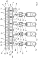
- FIG. 1 a schematic perspective view of a detail of an embodiment of the system according to the invention is shown.
- FIG 2 12 is another schematic perspective and fragmentary view of the embodiment of the system of FIG figure 1 shown.
- the system comprises a non-driven transfer chain 3 and a driven conveyor chain 4.
- the two chains 3, 4 are arranged one above the other in the system.
- Both the transfer chain 3 and the conveyor chain 4 are designed as roller chains in the embodiment shown.
- the transfer chain 3 has outer link plates 3a, inner link plates 3b, link pins 3c and rollers 3d.
- the transfer chain 3 includes a large number of the aforementioned components. However, for the sake of simplicity, only one pair of each component is shown.
- the transfer chain 3 also has an adapter bracket 1 .
- the adapter bracket 1 in the present embodiment has two driver tines 1b, which are arranged at a distance from one another like the tines of a fork.
- the adapter bracket 1 it is of course possible for the adapter bracket 1 to have one or more than two driver prongs 1b.
- the tines 1b are parallel offset to the base body 1a of the adapter bracket 1 is arranged.
- the resulting z-shape of the adapter bracket 1 can be seen clearly in both figures.
- the driver tines 1b also extend parallel to the chain pins 3c of the transfer chain 3, which can also be clearly seen in the aforementioned figures.
- the transfer chain 3 also includes a pinion tooth 2.
- the pinion tooth 2 is attached to the adapter bracket 1, more precisely, to the base body 1a of the adapter bracket 1.
- the pinion tooth 2 is arranged on the same side of the z-shaped adapter bracket 1 to which the driver tines 1b are also arranged offset.
- the pinion tooth 2 is by means of a snap connection (see also figure 4 ) detachably attached.
- the size and shape of the pinion tooth 2 can, for example, correspond to that of a tooth from a sprocket with 36 teeth.
- the pinion tooth 2 can also be attached to another part of the transfer chain 3, for example to an additional positioning and fastening element, or by means of an alternative form-fitting connection or a force-fitting connection, for example a screw connection, to the transfer chain 3. It is also possible for the pinion tooth 2 to be attached directly to the transfer chain 3, with the pinion tooth 2 then having a shape or structure corresponding to the intended use.
- the driven conveyor chain 4 also has driver fingers 4e, which in the embodiment shown represent an extension of the chain pins 4c.
- the conveyor chain 4 includes a large number of the aforementioned components. Again, only one pair of each component is shown for the sake of simplicity.
- driver tines 1b are arranged at the same height as the driver fingers 4e (see also Fig figure 3 ).
- FIG 3 a combined schematic and partial view comprising a sectional view of driver prongs 1b and driver fingers 4e and a top view of the holding adapter 5 is shown.
- Each holding adapter 5 has a head part 5a, a neck part 5b, two conveyor rollers 5c and one not shown (see figure 5 ) Interface 5d for receiving an object 10 to be transported.
- the holding adapter 5 is designed differently, ie has other, fewer or additional components.
- driver prongs 1b of the adapter bracket 1 have the same pitch as the driver fingers 4e of the conveyor chain 4 and that the driver prongs 1b and driver fingers 4e, which are arranged parallel or at the same height, rest on or engage the head part 5a of the holding adapter 5.
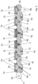
- FIG 4 a schematic and partial sectional view of a conveyor chain 4 and pinion teeth 2 engaging therein is shown.
- each pinion tooth 2 engages in the conveyor chain 4 .
- the pinion tooth 2 is located between two rollers 4d.
- the shape of the pinion tooth 2 can also be clearly seen in this view.
- the pinion tooth 2 has conically running flanks 2b, as a result of which the speeds of the two chains 3, 4 can be synchronized as smoothly as possible when the pinion tooth 2 engages with the conveyor chain 4.
- the snap connection with which the pinion tooth 2 is releasably attached to the base body 1a of the adapter bracket 1 comprises two snap hooks 2a in the embodiment shown.
- the snap hooks 2a engage around the base body 1a.
- the snap hooks 2a alternatively through the base body crack down.
- further “openings" of the pinion tooth 2 through the base body 1a are provided in the present case.
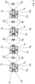
- FIG 5 12 is a schematic and fragmentary front view of the embodiment of the system of FIG figure 1 and several holding adapters 5 are shown.
- the holding adapters 5 also shown have an interface 5d for holding the objects 10 to be transported.
- the holding adapters 5 also have a conveyor roller 5c in the area of their neck part 5b and a head part 5a arranged above them. At the head part 5a is attacked by the conveyor chain 4, but also by the transfer chain 3 for further transport of the holding adapter 5.
- FIG 6 a schematic and partial top view of an embodiment of the conveyor device 100 according to the invention is shown.
- the excerpt or section shown can be referred to as a sorting section.
- the conveyor device 100 has a first rail profile 101 there, with the objects to be transported being transported along the first rail profile 101 .
- the objects to be transported are placed in the first rail profile 101 at a loading point (not shown).
- the conveyor chain 4 of the first rail profile 101 can be continuously moved in this in a conveying direction x 1 .
- the conveyor chain 4 can be driven in particular with the aid of friction rollers arranged along the first rail profile 101 .
- the holding adapters 5 are mounted and guided in the first rail profile 101 such that they can be rolled.
- the head part 5a of the holding adapter 5 can be coupled to the conveyor chain 4, as is the case, for example, in FIGS figures 4 and 5 is shown.
- Switches 103 are arranged at a number of positions along the first rail profile 101, by means of which retaining adapter 5 and any objects 10 stored thereon can be transferred to a second rail profile 102.
- the switches 103 are controlled or switched on the basis of a previous identification of the holding adapter 5 or the objects 10 .
- the identification can take place, for example, when the holding adapter 5 and thus the object 10 attached to it are placed in the first rail profile 101 .
- the switch 103 would then be controlled or switched by counting cycles, each corresponding to a predefined distance of the first rail profile 101, since the holding adapter 5 and thus the object 10 attached to it were placed in the first rail profile 101.
- the identification can be carried out by means of an identification unit which is arranged in a region of the first rail profile 101 in front of the respective points 103 and is also referred to as a reading unit.
- an identification unit which is arranged in a region of the first rail profile 101 in front of the respective points 103 and is also referred to as a reading unit.
- the identification shows that the holding adapter 5 or the object 10 to be transported is to be conveyed out of the first rail profile 101 via the switch 103
- an actuating element of the switch 103 is switched over accordingly, so that the holding adapter 5 can be moved during further transport by switching the Switch 103 in a rail profile 103a (see figure 7 ) of switch 103 is transferred and from there into the second rail profile 102 is transferred and transported further along the second rail profile 102 . If this does not result from the identification, transport continues along the first rail profile 101 .
- the second rail profiles 102 serve as a temporary storage facility in which the objects to be transported 10 are temporarily stored.
- the objects 10 stored on the second rail profile 102 can be further transported via further points 103 into a third rail profile 104 .
- FIG. 12 is a schematic sectional view of a switch 103 of the conveyor device 100.
- the retaining adapter 5 and thus any objects 10 stored thereon can be transferred from the first rail profile 101 to a second rail profile 102 or from the second rail profile 102 to the third rail profile 104 by means of the switch 103 .
- the switch 103 has an actuating element (not shown) and a rail profile 103a in which the head part 5a of the respective holding adapter 5 is mounted and guided.
- the switch 103 has a transfer chain 3 for transporting the holding adapter 5 and the objects hanging from it.
- the transfer chain 3 is deflected via sprockets 103b.
- the transfer chain 3 has, as in the Figures 1 to 5 is shown, adapter brackets 1 with driver prongs 1b for further transport of the holding adapter 5.
- the driver prongs 1b are in contact with the respective head parts 5a of the holding adapters 5 and move the holding adapters 5 towards them along the first rail profile 101 the second rail profile 102 or along the second rail profile 102 towards the third rail profile 104.
- the switch 103 does not have its own drive.
- the transfer chain 3 is driven by a coupling produced by means of pinion teeth 2 with a conveyor chain 4, which takes place in the coupling area A.
Landscapes
- Engineering & Computer Science (AREA)
- Mechanical Engineering (AREA)
- Intermediate Stations On Conveyors (AREA)
- Chain Conveyers (AREA)
Applications Claiming Priority (1)
| Application Number | Priority Date | Filing Date | Title |
|---|---|---|---|
| DE102022105189.7A DE102022105189A1 (de) | 2022-03-04 | 2022-03-04 | Transferzugmittel sowie System und Fördervorrichtung mit einem solchen Transferzugmittel |
Publications (1)
| Publication Number | Publication Date |
|---|---|
| EP4238909A1 true EP4238909A1 (fr) | 2023-09-06 |
Family
ID=85415258
Family Applications (1)
| Application Number | Title | Priority Date | Filing Date |
|---|---|---|---|
| EP23159498.7A Pending EP4238909A1 (fr) | 2022-03-04 | 2023-03-01 | Moyen de traction de transfert, système et dispositif de transport comprenant un tel moyen de traction de transfert |
Country Status (3)
| Country | Link |
|---|---|
| US (1) | US12344479B2 (fr) |
| EP (1) | EP4238909A1 (fr) |
| DE (1) | DE102022105189A1 (fr) |
Citations (6)
| Publication number | Priority date | Publication date | Assignee | Title |
|---|---|---|---|---|
| DE202014007861U1 (de) * | 2014-10-01 | 2014-11-18 | Jensen Sweden Ab | Befestigungselement zum Befestigen eines Mitnehmers an einer Kette |
| EP2886494A1 (fr) | 2013-12-23 | 2015-06-24 | SDI Group Germany Material Handling Solutions GmbH | Dispositif de transport pour le transport d'objets suspendus |
| EP2918520A1 (fr) * | 2014-03-11 | 2015-09-16 | Ferag AG | Procédé et dispositif de distribution de marchandises au détail à partir d'un dispositif de transport |
| EP3028960A1 (fr) * | 2014-11-27 | 2016-06-08 | Vanderlande Industries B.V. | Procede destine a desserrer un element de transport d'un support de transport d'une chaine a raclettes pour transporter une marchandise suspendue, chaine a raclettes, support de transport et element de transport |
| EP3225571A1 (fr) | 2016-03-29 | 2017-10-04 | Dematic GmbH | Dispositif de transport d'objets suspendus |
| EP3750834A1 (fr) * | 2019-06-11 | 2020-12-16 | BEUMER Group GmbH & Co. KG | Dispositif de séparation, dispositif de traction pourvu d'au moins un dispositif de séparation, système de transport et procédé de séparation et d'entraînement d'au moins un porteur de charge |
Family Cites Families (4)
| Publication number | Priority date | Publication date | Assignee | Title |
|---|---|---|---|---|
| DE10135659A1 (de) | 2001-07-21 | 2003-02-06 | Kolbus Gmbh & Co Kg | Fördereinrichtung zur Förderung von Gegenständen, insbesondere von Druckprodukten |
| US20070182953A1 (en) | 2006-02-06 | 2007-08-09 | Tassic Donald T | Inspection apparatus for conveyor system |
| DE102014105767B4 (de) | 2014-04-24 | 2018-01-04 | Fintec Textilpflegesysteme Gmbh | Schleppklinke für einen Klinkenförderer |
| DE102015002185A1 (de) * | 2015-02-20 | 2016-08-25 | Interroll Holding Ag | Befestigungselement zum Befestigen eines Laufwagens an einem Endlosfördermittel, Laufwagen, Fördervorrichtung und Befestigungsverfahren |
-
2022
- 2022-03-04 DE DE102022105189.7A patent/DE102022105189A1/de active Pending
-
2023
- 2023-03-01 EP EP23159498.7A patent/EP4238909A1/fr active Pending
- 2023-03-03 US US18/178,063 patent/US12344479B2/en active Active
Patent Citations (6)
| Publication number | Priority date | Publication date | Assignee | Title |
|---|---|---|---|---|
| EP2886494A1 (fr) | 2013-12-23 | 2015-06-24 | SDI Group Germany Material Handling Solutions GmbH | Dispositif de transport pour le transport d'objets suspendus |
| EP2918520A1 (fr) * | 2014-03-11 | 2015-09-16 | Ferag AG | Procédé et dispositif de distribution de marchandises au détail à partir d'un dispositif de transport |
| DE202014007861U1 (de) * | 2014-10-01 | 2014-11-18 | Jensen Sweden Ab | Befestigungselement zum Befestigen eines Mitnehmers an einer Kette |
| EP3028960A1 (fr) * | 2014-11-27 | 2016-06-08 | Vanderlande Industries B.V. | Procede destine a desserrer un element de transport d'un support de transport d'une chaine a raclettes pour transporter une marchandise suspendue, chaine a raclettes, support de transport et element de transport |
| EP3225571A1 (fr) | 2016-03-29 | 2017-10-04 | Dematic GmbH | Dispositif de transport d'objets suspendus |
| EP3750834A1 (fr) * | 2019-06-11 | 2020-12-16 | BEUMER Group GmbH & Co. KG | Dispositif de séparation, dispositif de traction pourvu d'au moins un dispositif de séparation, système de transport et procédé de séparation et d'entraînement d'au moins un porteur de charge |
Also Published As
| Publication number | Publication date |
|---|---|
| US20230278805A1 (en) | 2023-09-07 |
| DE102022105189A1 (de) | 2023-09-07 |
| US12344479B2 (en) | 2025-07-01 |
Similar Documents
| Publication | Publication Date | Title |
|---|---|---|
| DE2815353C2 (de) | Vorrichtung zum wahlweisen Umsetzen von Stückgütern | |
| DE2328206A1 (de) | Antriebsschiene fuer einen foerderer | |
| EP2428471B1 (fr) | Convoyeur | |
| DE3926735A1 (de) | Verfahren und vorrichtung zum zufuehren von flaschen oder dgl. | |
| EP2314529B1 (fr) | Unité de transport dotée de chaînes à petits rouleaux de retenue | |
| CH688279A5 (de) | Elastischer Greifer fuer die Mitnehmer von Schleppkettenförderern. | |
| AT500087A1 (de) | Vereinzelungseinrichtung für langteile sowie vorrichtung zum transport derselben | |
| WO2022122792A2 (fr) | Dispositif d'éjection | |
| EP2366640A2 (fr) | Unité de transport pour un système de transport pour articles | |
| DE60219978T2 (de) | Vorrichtung zum Anordnen von Behältern, insbesondere von Flaschen, in gleichen Abständen | |
| EP0681923A1 (fr) | Assembleuse et brocheuse combinées | |
| EP4238909A1 (fr) | Moyen de traction de transfert, système et dispositif de transport comprenant un tel moyen de traction de transfert | |
| EP0252461B1 (fr) | Dispositif de modification d'un flux de bouteilles à plusieurs rangs en un flux de bouteilles à un seul rang | |
| DE4314644B4 (de) | Vorrichtung zum Ablegen flacher Gegenstände in Hochkantlage auf einem Transportband oder dergleichen | |
| DE20200794U1 (de) | Vorrichtung zum Verteilen von Behältern | |
| DE112024002306T5 (de) | Vorrichtung zum auf- oder verteilen von aus einem ersten förderabschnitt kommenden einzelprodukten auf einen mehrere bahnreihen aufweisenden zweiten förderabschnitt | |
| DE69411786T2 (de) | Stapelvorrichtung | |
| DE102017222853B4 (de) | Fördervorrichtung | |
| DE19829176B4 (de) | Einrichtung an einer Verpackungsmaschine | |
| DE29521082U1 (de) | Gruppier- und Puffervorrichtung | |
| EP3502015B1 (fr) | Dispositif de transport | |
| DE29519805U1 (de) | Transfereinrichtung für Fördergut | |
| DE10124131A1 (de) | Fördersystem | |
| WO2021078506A1 (fr) | Dispositif de chargement de récipients pour une machine de traitement de récipients | |
| DE10239819B4 (de) | Vorrichtung zum Spannen eines flexiblen Fördermittels |
Legal Events
| Date | Code | Title | Description |
|---|---|---|---|
| PUAI | Public reference made under article 153(3) epc to a published international application that has entered the european phase |
Free format text: ORIGINAL CODE: 0009012 |
|
| STAA | Information on the status of an ep patent application or granted ep patent |
Free format text: STATUS: THE APPLICATION HAS BEEN PUBLISHED |
|
| AK | Designated contracting states |
Kind code of ref document: A1 Designated state(s): AL AT BE BG CH CY CZ DE DK EE ES FI FR GB GR HR HU IE IS IT LI LT LU LV MC ME MK MT NL NO PL PT RO RS SE SI SK SM TR |
|
| STAA | Information on the status of an ep patent application or granted ep patent |
Free format text: STATUS: REQUEST FOR EXAMINATION WAS MADE |
|
| 17P | Request for examination filed |
Effective date: 20240221 |
|
| RBV | Designated contracting states (corrected) |
Designated state(s): AL AT BE BG CH CY CZ DE DK EE ES FI FR GB GR HR HU IE IS IT LI LT LU LV MC ME MK MT NL NO PL PT RO RS SE SI SK SM TR |