EP4238932A1 - Système à double pression pour la production d'acide nitrique et son procédé de fonctionnement - Google Patents
Système à double pression pour la production d'acide nitrique et son procédé de fonctionnement Download PDFInfo
- Publication number
- EP4238932A1 EP4238932A1 EP22160016.6A EP22160016A EP4238932A1 EP 4238932 A1 EP4238932 A1 EP 4238932A1 EP 22160016 A EP22160016 A EP 22160016A EP 4238932 A1 EP4238932 A1 EP 4238932A1
- Authority
- EP
- European Patent Office
- Prior art keywords
- gas
- oxygen
- stream
- tail gas
- gas stream
- Prior art date
- Legal status (The legal status is an assumption and is not a legal conclusion. Google has not performed a legal analysis and makes no representation as to the accuracy of the status listed.)
- Withdrawn
Links
- GRYLNZFGIOXLOG-UHFFFAOYSA-N Nitric acid Chemical compound O[N+]([O-])=O GRYLNZFGIOXLOG-UHFFFAOYSA-N 0.000 title claims abstract description 118
- 229910017604 nitric acid Inorganic materials 0.000 title claims abstract description 118
- 238000000034 method Methods 0.000 title claims abstract description 69
- 230000009977 dual effect Effects 0.000 title abstract description 20
- 239000007789 gas Substances 0.000 claims abstract description 957
- QVGXLLKOCUKJST-UHFFFAOYSA-N atomic oxygen Chemical compound [O] QVGXLLKOCUKJST-UHFFFAOYSA-N 0.000 claims abstract description 358
- 239000001301 oxygen Substances 0.000 claims abstract description 358
- 229910052760 oxygen Inorganic materials 0.000 claims abstract description 358
- 238000004519 manufacturing process Methods 0.000 claims abstract description 91
- 238000004891 communication Methods 0.000 claims abstract description 45
- 239000012530 fluid Substances 0.000 claims abstract description 43
- QGZKDVFQNNGYKY-UHFFFAOYSA-N Ammonia Chemical compound N QGZKDVFQNNGYKY-UHFFFAOYSA-N 0.000 claims description 394
- 229910021529 ammonia Inorganic materials 0.000 claims description 184
- 238000010521 absorption reaction Methods 0.000 claims description 101
- MWUXSHHQAYIFBG-UHFFFAOYSA-N Nitric oxide Chemical compound O=[N] MWUXSHHQAYIFBG-UHFFFAOYSA-N 0.000 claims description 87
- 239000000203 mixture Substances 0.000 claims description 76
- XLYOFNOQVPJJNP-UHFFFAOYSA-N water Substances O XLYOFNOQVPJJNP-UHFFFAOYSA-N 0.000 claims description 66
- 238000002156 mixing Methods 0.000 claims description 62
- 238000011144 upstream manufacturing Methods 0.000 claims description 47
- 230000001276 controlling effect Effects 0.000 claims description 23
- 238000004061 bleaching Methods 0.000 claims description 22
- 238000010438 heat treatment Methods 0.000 claims description 20
- MYMOFIZGZYHOMD-UHFFFAOYSA-N Dioxygen Chemical compound O=O MYMOFIZGZYHOMD-UHFFFAOYSA-N 0.000 claims description 10
- 229910001882 dioxygen Inorganic materials 0.000 claims description 10
- 238000001816 cooling Methods 0.000 claims description 9
- GNFTZDOKVXKIBK-UHFFFAOYSA-N 3-(2-methoxyethoxy)benzohydrazide Chemical compound COCCOC1=CC=CC(C(=O)NN)=C1 GNFTZDOKVXKIBK-UHFFFAOYSA-N 0.000 claims description 8
- 230000001105 regulatory effect Effects 0.000 claims description 8
- YTAHJIFKAKIKAV-XNMGPUDCSA-N [(1R)-3-morpholin-4-yl-1-phenylpropyl] N-[(3S)-2-oxo-5-phenyl-1,3-dihydro-1,4-benzodiazepin-3-yl]carbamate Chemical compound O=C1[C@H](N=C(C2=C(N1)C=CC=C2)C1=CC=CC=C1)NC(O[C@H](CCN1CCOCC1)C1=CC=CC=C1)=O YTAHJIFKAKIKAV-XNMGPUDCSA-N 0.000 claims description 3
- 230000009467 reduction Effects 0.000 abstract description 2
- 229910002089 NOx Inorganic materials 0.000 description 212
- 239000003570 air Substances 0.000 description 149
- WFPZPJSADLPSON-UHFFFAOYSA-N dinitrogen tetraoxide Chemical compound [O-][N+](=O)[N+]([O-])=O WFPZPJSADLPSON-UHFFFAOYSA-N 0.000 description 20
- UFHFLCQGNIYNRP-UHFFFAOYSA-N Hydrogen Chemical compound [H][H] UFHFLCQGNIYNRP-UHFFFAOYSA-N 0.000 description 18
- 230000008569 process Effects 0.000 description 17
- MGWGWNFMUOTEHG-UHFFFAOYSA-N 4-(3,5-dimethylphenyl)-1,3-thiazol-2-amine Chemical compound CC1=CC(C)=CC(C=2N=C(N)SC=2)=C1 MGWGWNFMUOTEHG-UHFFFAOYSA-N 0.000 description 16
- 238000006243 chemical reaction Methods 0.000 description 11
- JCXJVPUVTGWSNB-UHFFFAOYSA-N nitrogen dioxide Inorganic materials O=[N]=O JCXJVPUVTGWSNB-UHFFFAOYSA-N 0.000 description 11
- 230000003647 oxidation Effects 0.000 description 11
- 238000007254 oxidation reaction Methods 0.000 description 11
- 239000006096 absorbing agent Substances 0.000 description 10
- BASFCYQUMIYNBI-UHFFFAOYSA-N platinum Chemical compound [Pt] BASFCYQUMIYNBI-UHFFFAOYSA-N 0.000 description 8
- 239000000243 solution Substances 0.000 description 8
- 230000008901 benefit Effects 0.000 description 7
- 239000001257 hydrogen Substances 0.000 description 7
- 229910052739 hydrogen Inorganic materials 0.000 description 7
- 230000001965 increasing effect Effects 0.000 description 7
- CURLTUGMZLYLDI-UHFFFAOYSA-N Carbon dioxide Chemical compound O=C=O CURLTUGMZLYLDI-UHFFFAOYSA-N 0.000 description 6
- 239000003054 catalyst Substances 0.000 description 6
- 238000005868 electrolysis reaction Methods 0.000 description 5
- GQPLMRYTRLFLPF-UHFFFAOYSA-N Nitrous Oxide Chemical compound [O-][N+]#N GQPLMRYTRLFLPF-UHFFFAOYSA-N 0.000 description 4
- IOVCWXUNBOPUCH-UHFFFAOYSA-N Nitrous acid Chemical compound ON=O IOVCWXUNBOPUCH-UHFFFAOYSA-N 0.000 description 4
- 239000012080 ambient air Substances 0.000 description 4
- 229910002092 carbon dioxide Inorganic materials 0.000 description 4
- 230000003197 catalytic effect Effects 0.000 description 4
- VNWKTOKETHGBQD-UHFFFAOYSA-N methane Chemical compound C VNWKTOKETHGBQD-UHFFFAOYSA-N 0.000 description 4
- 229910052697 platinum Inorganic materials 0.000 description 4
- KWYUFKZDYYNOTN-UHFFFAOYSA-M Potassium hydroxide Chemical compound [OH-].[K+] KWYUFKZDYYNOTN-UHFFFAOYSA-M 0.000 description 3
- 239000003792 electrolyte Substances 0.000 description 3
- 238000011084 recovery Methods 0.000 description 3
- 239000000126 substance Chemical group 0.000 description 3
- OKTJSMMVPCPJKN-UHFFFAOYSA-N Carbon Chemical compound [C] OKTJSMMVPCPJKN-UHFFFAOYSA-N 0.000 description 2
- PXHVJJICTQNCMI-UHFFFAOYSA-N Nickel Chemical compound [Ni] PXHVJJICTQNCMI-UHFFFAOYSA-N 0.000 description 2
- MCMNRKCIXSYSNV-UHFFFAOYSA-N Zirconium dioxide Chemical compound O=[Zr]=O MCMNRKCIXSYSNV-UHFFFAOYSA-N 0.000 description 2
- 230000015572 biosynthetic process Effects 0.000 description 2
- 229910052799 carbon Inorganic materials 0.000 description 2
- 239000001569 carbon dioxide Substances 0.000 description 2
- 238000000354 decomposition reaction Methods 0.000 description 2
- 238000003795 desorption Methods 0.000 description 2
- 239000002360 explosive Substances 0.000 description 2
- 239000003517 fume Substances 0.000 description 2
- 239000005431 greenhouse gas Substances 0.000 description 2
- 238000009434 installation Methods 0.000 description 2
- 230000010354 integration Effects 0.000 description 2
- 230000004048 modification Effects 0.000 description 2
- 238000012986 modification Methods 0.000 description 2
- 239000002808 molecular sieve Substances 0.000 description 2
- 239000003345 natural gas Substances 0.000 description 2
- 229910000069 nitrogen hydride Inorganic materials 0.000 description 2
- 238000004886 process control Methods 0.000 description 2
- 230000008929 regeneration Effects 0.000 description 2
- 238000011069 regeneration method Methods 0.000 description 2
- 229910052703 rhodium Inorganic materials 0.000 description 2
- 239000010948 rhodium Substances 0.000 description 2
- MHOVAHRLVXNVSD-UHFFFAOYSA-N rhodium atom Chemical compound [Rh] MHOVAHRLVXNVSD-UHFFFAOYSA-N 0.000 description 2
- 238000000926 separation method Methods 0.000 description 2
- URGAHOPLAPQHLN-UHFFFAOYSA-N sodium aluminosilicate Chemical compound [Na+].[Al+3].[O-][Si]([O-])=O.[O-][Si]([O-])=O URGAHOPLAPQHLN-UHFFFAOYSA-N 0.000 description 2
- 238000001179 sorption measurement Methods 0.000 description 2
- 238000003786 synthesis reaction Methods 0.000 description 2
- 229920000557 Nafion® Polymers 0.000 description 1
- 229910000831 Steel Inorganic materials 0.000 description 1
- 239000000654 additive Substances 0.000 description 1
- 239000012670 alkaline solution Substances 0.000 description 1
- 230000004888 barrier function Effects 0.000 description 1
- 239000007795 chemical reaction product Substances 0.000 description 1
- 229910017052 cobalt Inorganic materials 0.000 description 1
- 239000010941 cobalt Substances 0.000 description 1
- GUTLYIVDDKVIGB-UHFFFAOYSA-N cobalt atom Chemical compound [Co] GUTLYIVDDKVIGB-UHFFFAOYSA-N 0.000 description 1
- 230000000052 comparative effect Effects 0.000 description 1
- 150000001875 compounds Chemical group 0.000 description 1
- 230000006835 compression Effects 0.000 description 1
- 238000007906 compression Methods 0.000 description 1
- 238000005115 demineralization Methods 0.000 description 1
- 230000002328 demineralizing effect Effects 0.000 description 1
- 238000010292 electrical insulation Methods 0.000 description 1
- 239000012777 electrically insulating material Substances 0.000 description 1
- 238000003411 electrode reaction Methods 0.000 description 1
- 230000003028 elevating effect Effects 0.000 description 1
- 230000002708 enhancing effect Effects 0.000 description 1
- 229920002313 fluoropolymer Polymers 0.000 description 1
- 239000004811 fluoropolymer Substances 0.000 description 1
- 239000000446 fuel Substances 0.000 description 1
- 229910052741 iridium Inorganic materials 0.000 description 1
- GKOZUEZYRPOHIO-UHFFFAOYSA-N iridium atom Chemical compound [Ir] GKOZUEZYRPOHIO-UHFFFAOYSA-N 0.000 description 1
- 239000007788 liquid Substances 0.000 description 1
- 239000011244 liquid electrolyte Substances 0.000 description 1
- 229910052759 nickel Inorganic materials 0.000 description 1
- 239000005518 polymer electrolyte Substances 0.000 description 1
- 238000000746 purification Methods 0.000 description 1
- 230000003134 recirculating effect Effects 0.000 description 1
- 239000007787 solid Substances 0.000 description 1
- 239000010959 steel Substances 0.000 description 1
- 230000001629 suppression Effects 0.000 description 1
- 239000002918 waste heat Substances 0.000 description 1
Images



Classifications
-
- C—CHEMISTRY; METALLURGY
- C01—INORGANIC CHEMISTRY
- C01B—NON-METALLIC ELEMENTS; COMPOUNDS THEREOF; METALLOIDS OR COMPOUNDS THEREOF NOT COVERED BY SUBCLASS C01C
- C01B21/00—Nitrogen; Compounds thereof
- C01B21/20—Nitrogen oxides; Oxyacids of nitrogen; Salts thereof
- C01B21/24—Nitric oxide (NO)
- C01B21/26—Preparation by catalytic or non-catalytic oxidation of ammonia
-
- C—CHEMISTRY; METALLURGY
- C01—INORGANIC CHEMISTRY
- C01B—NON-METALLIC ELEMENTS; COMPOUNDS THEREOF; METALLOIDS OR COMPOUNDS THEREOF NOT COVERED BY SUBCLASS C01C
- C01B21/00—Nitrogen; Compounds thereof
- C01B21/20—Nitrogen oxides; Oxyacids of nitrogen; Salts thereof
- C01B21/24—Nitric oxide (NO)
- C01B21/26—Preparation by catalytic or non-catalytic oxidation of ammonia
- C01B21/28—Apparatus
-
- C—CHEMISTRY; METALLURGY
- C01—INORGANIC CHEMISTRY
- C01B—NON-METALLIC ELEMENTS; COMPOUNDS THEREOF; METALLOIDS OR COMPOUNDS THEREOF NOT COVERED BY SUBCLASS C01C
- C01B21/00—Nitrogen; Compounds thereof
- C01B21/20—Nitrogen oxides; Oxyacids of nitrogen; Salts thereof
- C01B21/38—Nitric acid
-
- B—PERFORMING OPERATIONS; TRANSPORTING
- B01—PHYSICAL OR CHEMICAL PROCESSES OR APPARATUS IN GENERAL
- B01D—SEPARATION
- B01D2252/00—Absorbents, i.e. solvents and liquid materials for gas absorption
- B01D2252/10—Inorganic absorbents
- B01D2252/103—Water
-
- B—PERFORMING OPERATIONS; TRANSPORTING
- B01—PHYSICAL OR CHEMICAL PROCESSES OR APPARATUS IN GENERAL
- B01D—SEPARATION
- B01D2258/00—Sources of waste gases
- B01D2258/02—Other waste gases
-
- B—PERFORMING OPERATIONS; TRANSPORTING
- B01—PHYSICAL OR CHEMICAL PROCESSES OR APPARATUS IN GENERAL
- B01D—SEPARATION
- B01D53/00—Separation of gases or vapours; Recovering vapours of volatile solvents from gases; Chemical or biological purification of waste gases, e.g. engine exhaust gases, smoke, fumes, flue gases, aerosols
- B01D53/34—Chemical or biological purification of waste gases
- B01D53/46—Removing components of defined structure
- B01D53/54—Nitrogen compounds
- B01D53/56—Nitrogen oxides
Definitions
- the present disclosure relates to the field of nitric acid production in a dual pressure plant.
- nitric acid is a clear, colorless liquid with a strong odor.
- Nitric acid is produced in large quantities principally by catalytic oxidation of ammonia (Ostwald process). Ammonia is converted to nitric acid in several stages. Ammonia is first oxidized in an ammonia burner on platinum gauzes (commonly called ammonia converter) or cobalt balls, producing nitric oxide (in this disclosure also called nitrogen monoxide (NO)) and water: 4 NH 3 (g) + 5 O 2 (g) ⁇ 4 NO (g) + 6 H 2 O (g) (1)
- reaction product from (1), nitric oxide, following cooling, is then oxidized to nitrogen dioxide (NO 2 ) and further to dinitrogen tetroxide N 2 O 4 (g) in an oxidation section: 2 NO (g) + O 2 (g) ⁇ 2 NO 2 (g) (2) 2 NO 2 (g) ⁇ N 2 O 4 (g) (3)
- Cooling of nitrogen oxide gases is accomplished first through the use of a waste heat recovery system recovering the heat from the conversion of ammonia into nitric oxide, then through the use of a cooler condenser in which condensed nitric acid is separated from nitric oxide, nitrogen dioxide and dinitrogen tetroxide and nitric acid gases, collectively called NO x gases, and finally by heating the tail gas released at the outlet of the absorption tower in which the NO x gases are absorbed.
- nitric acid which is up to 68 % (azeotrope) is obtained.
- concentration of nitric acid can be increased up to 99 % concentrated nitric acid.
- the total reaction is given by the following formula: NH 3 + 2 O 2 ⁇ HNO 3 + H 2 O (6)
- the main process units in a nitric acid production plant include an ammonia converter (conversion of ammonia into nitric oxides using oxygen over a suitable catalyst), an oxidation section (conversion of nitric oxide into nitrogen dioxide and nitrogen tetroxide), an absorber unit (for the absorption of NO x gases into water) and a bleacher unit (removal of unreacted dissolved gases, containing in particular NO x and gases, from the aqueous nitric acid solution, which give it its typical brownish color).
- ammonia converter conversion of ammonia into nitric oxides using oxygen over a suitable catalyst
- an oxidation section conversion of nitric oxide into nitrogen dioxide and nitrogen tetroxide
- an absorber unit for the absorption of NO x gases into water
- a bleacher unit removal of unreacted dissolved gases, containing in particular NO x and gases, from the aqueous nitric acid solution, which give it its typical brownish color.
- the process for the production of nitric acid can be differentiated into a mono pressure (single-pressure) and dual pressure (split-pressure) process.
- the absorber unit operates at a higher working pressure than the ammonia converter.
- Modern dual pressure processes feature a low-pressure ammonia converter operating typically at 2 to 6 bara, and a high-pressure absorber unit operating at 9 to 16 bara.
- a dual pressure process requires an air compressor to feed low-pressure air (which comprises about 21 vol% of oxygen) to the converter, and a NO x gas compressor to feed high-pressure NO x gases to the absorber unit.
- the working pressure of an air compressor is from 2 to 6 bara, inclusive, and the working pressure of a NO x gas compressor is from 9 to 16 bara, inclusive.
- the drive power for the air compressor typically originates from a tail gas turbine and a steam turbine or a power source such as an electric motor.
- the compressor train of a dual pressure nitric acid production plant typically comprises an air compressor, a NO x gas compressor, a tail gas turbine, and a steam turbine or a power source such as an electric motor.
- a dual pressure plant and process works as follows.
- Gaseous ammonia 32 optionally pre-heated in a pre-heater unit (not shown) is mixed with compressed air 34 pressurised to a low pressure using an air compressor 36, in a mixing apparatus 35, and the resulting ammonia/oxygen-enriched air mixture 14 is fed to an ammonia converter 37, operating at a low pressure, where ammonia is oxidized over a suitable catalyst, thus obtaining a LP NO x gas/steam mixture 15, comprising water and nitric oxide (NO).
- a LP NO x gas/steam mixture comprising water and nitric oxide (NO).
- the heat of the mixture coming out of the ammonia converter is recovered, after which the NO x gas/stream mixture is subsequently cooled down in a gas cooler/condenser 38 to temperature where the water condenses, and an aqueous diluted nitric acid mixture 17 is separated from a gaseous NO x stream 22.
- the gaseous NO x stream 22 is sent to a NO x gas compressor 40 wherein its pressure is elevated from a low pressure to a high pressure, being about equal to the operating pressure of an absorber unit 41.
- the aqueous diluted nitric acid mixture 17 is sent to the absorber unit 41, commonly called absorption tower.
- the pressurised NO x gas stream 24 is further oxidized to further convert the NO to NO 2 and N 2 O 4 , cooled in an additional gas cooler/condenser 39 and then directed to the absorption tower 41.
- the pressurised NO x gas stream 24 reacts with water to produce the tail gas 5 and a stream of raw nitric acid 27 also containing residual NO x gas, which is fed to a bleacher 62.
- the residual NO x gas in the raw nitric acid stream 27 is then stripped out with a gaseous medium 72 such as an oxygen-containing gas or air, inside the bleacher unit 62 operating at low-pressure; the bleacher unit is generally operated at about the same pressure as the ammonia converter.
- the drive power for both the air compressor 36 and the NO x gas compressor 40 originates from a tail gas expander 7 and a steam turbine 51 or a power source such as an electric motor (not shown).
- the heat generated in the ammonia converter 37 is used for heating the tail gas 5 in the tail gas heat exchanger 43 comprising the heat exchangers 66 and 67, the tail gas heater being therefore optionally present.
- the tail gas 5 exchanges heat with the NO x gas/steam mixture 15 in the heat exchange system 43 and is expanded in the tail gas expander 7.
- the air used for the oxidation of ammonia is commonly denoted as primary air; the air used as stripping medium in the bleacher unit is commonly denoted as secondary air.
- primary air The air used as stripping medium in the bleacher unit
- secondary air the air used as stripping medium in the bleacher unit
- the revamping of the nitric acid production plants to increase its capacity is commonly based on increasing the amount of primary air to the reactor, which leads to a proportional increase of the amount of nitric acid produced.
- the increase of the amount of primary air in the reactor entails the installation of a new air compressor or the revamping of the existing one.
- the increase of the primary air also causes a higher amount of gas to be processed subsequently into the NO x gas compressor.
- This entails the further revamping of the NO x gas compressor or the installation of a new one, and the modification or replacement of the tail gas and/or the steam-turbines and/or the electrical motor. Otherwise, the NO x gas compressor would easily achieve its process limit, thus becoming the bottleneck of the plant.
- the revamping has significant drawbacks. First of all, it entails elevated costs for the modification or replacement of the existing equipment, i.e. the air compressor, the NO x gas compressor and the corresponding turbines and electrical motor. In addition, the revamping of the equipment is also technically demanding leading to long plant downtime.
- nitric acid production plants Another problem related to nitric acid production plants is the high amount of energy required in order to operate the air compressor. Consequently, a high amount of energy is required to achieve the targeted nitric acid production throughput.
- a goal of the present invention is to provide a system and a method for operating the system which allows for the reduction or even suppression of power required to operate the air compressor in a dual nitric acid plant.
- Nitric acid is produced by a medium pressure method, which is characterized in that it comprises the following steps: the ammonia oxidation and absorption pressure is 0.5-0.6 MPa; enabling the tail gas leaving the absorption tower to pass through a carbon molecular sieve Temperature Swing Adsorption (TSA) treatment device to reduce the content of nitrogen oxides in the tail gas to be less than 100mg/Nm 3 ; the process air of the air compressor is used as the regeneration desorption gas of the carbon molecular sieve temperature swing adsorption treatment device, and the regeneration desorption gas containing the nitrogen oxide can be returned to the ammonia oxidation reactor for reuse; adding a layer of N 2 O decomposition catalyst in the oxidation reactor to reduce the content of N 2 O to 50-100 PPM through reaction; the nitric acid bleaching tower is arranged at the bottom of the absorption tower, and the two towers are integrated
- the same amount of air is to be compressed as would be in the absence of the TSA unit: in the presence of the TSA unit, the amount of air being compressed is initially split between the TSA unit and the ammonia oxidation reactor directly and, in the end, with the amount of compressed air leaving the TSA unit being directed also to the ammonia oxidation reactor, the total amount of air compressed by the air compressor ends up in the ammonia oxidation reactor.
- WO2018162150A1 discloses a dual pressure plant for the production of nitric acid comprising a reactor providing a gaseous effluent containing nitrogen oxides, an absorber unit in which nitrogen oxides react with water providing raw nitric acid and, the absorber unit operating at a pressure greater than the pressure of the reactor, a compressor elevating the pressure of the reactor effluent to the absorber unit pressure, the plant also comprising a first HP bleacher unit and a second LP bleacher unit, the first HP bleacher unit stripping with air the NO x gas from the output stream of the absorber unit, thus providing a partially stripped nitric acid stream and a nitrogen oxides-loaded air stream, the former being fed to the second LP-bleacher unit and the latter being recycled to the oxidation section, upstream of the NO x gas compressor.
- a further air compressor is also provided, which supplies the first HP bleacher unit with air. Hence, energy is required in order to operate a first HP bleacher unit at a high-pressure and then recycle NO x gases to the delivery side of the NO x gas compressor.
- a production plant for producing nitric acid at reduced power consumption and reduced emissions comprising:
- the production plant further comprises a means for controlling the flow of the first and/or third tail gas stream.
- the production plant further comprises the production plant further comprises one or more of:
- the production plant further comprises a bleacher for bleaching the stream of raw nitric acid-containing residual NO x gas, to provide a stream of bleached nitric acid, having an inlet in fluid communication with a high-pressure water electrolyser supplying an oxygen-rich bleaching gas, and an outlet for off-gases in fluid communication with any gas stream downstream the ammonia converter and upstream the NO x gas compressor if the bleacher operates at a pressure equal to or higher than P1 and up to equal to P2, or in fluid communication with any stream downstream the NO x gas compressor and upstream the absorption tower and upstream the absorption tower if the bleacher operates at a pressure higher than P2, such that the supply for the second oxygen-containing gas comes at least partly from the off-gases.
- a bleacher for bleaching the stream of raw nitric acid-containing residual NO x gas, to provide a stream of bleached nitric acid, having an inlet in fluid communication with a high-pressure water electrolyser supplying an
- the production plant further comprises a stream of a second oxygen-rich gas in direct fluid communication with any tail gas stream, particularly a stream of a pressurized oxygen-rich gas in direct fluid communication with any tail gas stream upstream the first pressure release means.
- the production plant further comprises the first oxygen-rich gas, the second oxygen-rich gas, the second oxygen-containing gas, the oxygen-rich bleaching gas and the off-gases are all at least partly provided by a high-pressure water electrolyser.
- a method for producing nitric acid at reduced power consumption and reduced emissions, in a production plant according to the production plant of the disclosure comprises the steps of:
- the method further comprises the step of: q) adjusting the flow of the first and/or the third tail gas stream.
- the first tail gas stream is mixed in step I), and wherein the expanded tail gas is splitted in step k), and wherein the method further comprises the steps of:
- the third tail gas stream is mixed in step I), and wherein the tail gas obtained in step g) is splitted in step k) into a third tail gas stream and a fourth tail gas stream.
- the method further comprises the step of: v) bleaching the stream of raw nitric acid-containing residual NO x gas obtained in step g) in the bleacher, thereby producing the stream of bleached nitric acid.
- the method further comprises the step of: w) supplying the stream of the second oxygen-rich gas, particularly as a stream of a pressurized oxygen-rich gas, to a tail gas stream, particularly upstream the first pressure release means.
- the method further comprises the step of:
- method for revamping a production plant for producing nitric acid comprising:
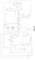
- first pressure release means 10 first tail gas stream 14 ammonia/oxygen-containing gas mixture 15 NO x gas/steam mixture 17 aqueous diluted nitric acid mixture 18, 22 gaseous NO x stream 24 compressed NO x gas having a pressure P2 27 stream of raw nitric acid-containing residual NO x gas 32 ammonia 34 compressed air 35 mixing apparatus 36 air compressor 37 ammonia converter operable at a pressure equal to or higher than P1 and lower than P2 38 gas cooler/condenser 39 additional gas cooler/condenser 40 NO x gas compressor 41 absorption tower 43 heat exchange system 50 first oxygen-rich gas 51 steam turbine 55 first means for splitting a tail gas stream 56 first oxygen-containing gas 60 second pressure release means 62 bleacher 63 high-pressure water electrolyser 64 expanded tail gas 66 first heat exchanger of the heat exchange system 43 67 second heat exchanger of the heat exchange system 43 68 second oxygen-containing gas having a pressure equal to or higher than P1 and up
- a production plant for producing nitric acid at reduced power consumption and reduced emissions comprising an air compressor 36 providing compressed air 34; a supply for a first oxygen-rich gas 50 in fluid communication with compressed air 34, the mixing of the first oxygen-rich gas 50 and of compressed air 34 providing part of a first oxygen-containing gas 56; a mixing apparatus 35, for mixing the first oxygen-containing gas 56 with an ammonia gas stream 32, to produce an ammonia/oxygen-containing gas mixture 14; an ammonia converter 37 operable at a pressure equal to or higher than P1 and lower than P2, for oxidising ammonia in the ammonia/oxygen-containing gas mixture 14, to produce a NO x gas/steam mixture 15 comprising water and nitric oxide; a means for regulating the concentration of ammonia and/or of oxygen in the ammonia converter 37, particularly a means for controlling the flow of the first oxygen-rich gas 50 in the oxygen-containing gas 56 and/or a means for controlling the flow of the ammonia gas stream
- the production plant is characterised in that the production plant further comprises a first and/or a second means for splitting 55, 82 a gas stream, wherein (i) the first means for splitting 55 is a means for splitting a tail gas stream into a first tail gas stream 10 and a second tail gas stream 80, wherein the first tail gas stream 10 has a pressure equal to or higher than P1 and up to P2 and is in fluid communication with the first oxygen-rich gas 50 and compressed air 34, and wherein the mixing of compressed air 34, the first oxygen-rich gas 50 and the first tail gas stream 10 provides the first oxygen-containing gas 56, and (ii) the second means for splitting 82 is a means for splitting a tail gas stream into a third tail gas stream 83 and a fourth tail gas stream 85, wherein the third tail gas stream 83 has a pressure equal to or higher than P1 and up to P2 and is in fluid communication with compressed air 34 and the first oxygen-rich gas 50, and wherein the mixing of the third tail gas 83, compressed air 34 and the first oxygen-rich
- an oxygen-rich gas is a gas comprising more than 21 vol% of oxygen, more in particular more than 30 vol%, more than 35 vol%, more than 40 vol%, more than 50 vol%, more than 60 vol%, more than 70 vol%, more than 80 vol%, more than 90 vol%, more than 95 vol%, more than 98 vol% and more than 99 vol%, more in particular 100 vol% of oxygen.
- An oxygen-rich gas can, for example, be provided by an air separation unit or by a water electrolyser.
- steam is water vapours.
- flow refers to either a volumetric flow or a mass flow.
- the heat exchange system 43 comprises at least two heat exchangers 66, 67.
- the person skilled in the art will realise that it is possible to split a stream of tail gas inside the heat exchange system, for example between the heat exchanger 66 and 67.
- the production plant comprises further heat exchange systems, such that the gaseous NO x stream 22 or the NO x compressed gas stream 24 exchange heat with the tail gas 5.
- a tail gas stream is any gas stream provided downstream the absorption tower, between the absorption tower 41 and the communication between the first tail gas stream 52 and the first oxygen-rich gas 50.
- a means for splitting is any means suitable for splitting a tail gas stream such as to generate e.g. a first tail gas stream 10 and a second sail gas stream 80, or a third tail gas stream 83,84 and a fourth tail gas stream 85.
- the means for splitting is a T-connection having one inlet and two outlets, such that a gas flowing through the inlet of the T-connection is splitted into two gas streams of identical chemical composition.
- pressure release means is any suitable means for reducing the pressure of a gas stream.
- the pressure release means is a gas expander or a gas ejector.
- the gas ejector provides the benefits of a simplified equipment, at the same time as the pressure of the tail gas stream being processed through the ejector is reduced.
- This tail gas stream being processed through the gas ejector is the motive gas and the second gas fed to the ejector can, for example, be ambient air at a pressure lower than the tail gas stream being processed through the gas ejector, for example atmospheric pressure.
- the tail gas stream is fed as the motive gas to the ejector and the second gas fed to the ejector is oxygen at a pressure lower than the tail gas stream being processed through the gas ejector.
- Both the feeding of air or oxygen through the gas ejector contribute to increasing the concentration in the first tail gas stream 10 and/or the third tail gas stream 83, 84 being recycled, thereby reducing the demand on the first oxygen-rich gas 50.
- the tail gas stream is fed as the motive gas to the ejector and the second gas fed to the ejector is the NO x gas/steam mixture 15 or the gaseous NO x stream 22.
- the means for splitting can be incorporated inside the pressure release means, provided that the pressure release means includes at least two outlets for the gas stream being depressurised.
- a means for regulating the concentration of ammonia and/or of oxygen is any means for suitable for achieving a target concentration of ammonia and/or of oxygen.
- gas flow control means in particular a flow control valve or an orifice or a guide vane, for controlling the flow of the first oxygen-rich gas 50 and/or of the ammonia gas stream 32.
- the means is an integrated process control system, in which the concentration of oxygen is measured and the target flow of oxygen is thereby determined and achieved from controlling the flow of the first oxygen-rich gas 50.
- the oxygen concentration can also be determined from computing, by using the oxygen concentration of the first oxygen-rich gas 50, the flow at which the first oxygen-rich gas 50 and of the ammonia gas stream 32 are introduced in the system, and the relative flow values at which the first oxygen-rich gas 50 and the ammonia gas stream 32 are mixed.
- P1 ranges from 2 to 6 bara and P2 ranges from 9 to 16 bara.
- the person skilled in the art will determine the optimal concentrations of oxygen in the gases entering the ammonia converter 37 and the absorption tower 41, in order for the catalytic conversion of ammonia to nitric oxide to proceed optimally in the ammonia converter 37 and for the absorption of NO x gases in the absorption tower 41 to proceed optimally.
- the person skilled in the art will also weigh out the benefits of increasing the oxygen content in the absorption tower 41, namely a reduced tower size due to improved absorption, against the drawback of a higher gas volume downstream the absorption tower 41, which implies equipment, such as heat exchangers, of a larger size, for heating tail gas.
- the inventors have found that, instead of supplying primary and secondary air solely as compressed air 34 provided by an air compressor 36, it is possible to recirculate the first tail gas stream 10 and/or the third tail gas stream 83, 84, provided by the first means for splitting 55 and the second means for splitting 82, respectively, particularly when controlling the oxygen content of the recirculated tail gas stream.
- the first oxygen-rich gas 50 having a pressure P1 and the second oxygen-containing gas 68 respectively provide oxygen to the ammonia converter 37 and to the absorption tower 41, such that, even at reduced amounts of compressed air 34 air provided by the air compressor 36, the concentration of oxygen in the ammonia converter 37 and in the absorption tower 41 is at least equal to that in a state-of-the-art dual pressure nitric acid plant.
- the person skilled in the art will realise that, if the pressure of the first oxygen-rich gas 50 is at a pressure such that the pressure of the first oxygen-containing gas 56 is, the relevant pressure drop being accounted for, lower than the operating pressure of the ammonia converter 37, the first oxygen-rich gas 50 can be compressed through the air compressor 36. The fluid communication between compressed air and the first oxygen-rich gas 50 is then introduced inside the air compressor 36.
- tail gas can be recirculated both as primary and secondary air. Consequently, less compressed air 34 is to be supplied such that less air has to be compressed and the power demand on the air compressor 34 is reduced.
- the size of the air compressor 36 and that of a conventional second pressure release means 60, in which the tail gas 5 is expanded in a state-of-the-art dual pressure nitric acid plant are reduced, such that the footprint of the plant is reduced.
- the NO x emissions leaving the production plant are also reduced. Consequently, the size of the treatment unit for treating those NO x emissions is reduced with respect to the size in the corresponding state-of-the art dual pressure nitric acid plant.
- the production plant further comprises a means for controlling the flow of the first and/or third tail gas stream 10, 83, 84.
- control of the flow of the first tail gas 10 enables to retain further control on the pressure and temperature inside the ammonia converter 37.
- control of the flow of the third tail gas 83, 84 enables to retain further control on the pressure and temperature inside the absorption tower 41.
- the production plant further comprises the production plant further comprises one or more of a steam turbine 51, wherein the steam turbine can at least partly power the NO x gas compressor 40; a heat exchanger 79, for exchanging heat between the first expanded tail gas 64 and a tail gas stream 5 wherein the first expanded tail gas exits the heat exchanger 79 at a temperature below 300 °C, wherein the first expanded tail gas 64 having exchanged heat with the tail gas 5 is further supplied to the first means for splitting 55, and/or the tail gas 5 at the outlet 6 of the absorption tower 41 is splitted into a third tail gas stream 83, 84 and a fourth tail gas stream 85; a De-NO x treatment unit 70; and a second pressure release means 60 for expanding the second tail gas stream 80 to atmospheric pressure, to produce a second expanded tail gas 69.
- a steam turbine 51 wherein the steam turbine can at least partly power the NO x gas compressor 40
- a heat exchanger 79 for exchanging heat between the first expanded tail gas 64 and a tail gas stream 5 wherein the
- means for converting steam into power are any mean for achieving power from steam.
- those means are a steam turbine connected to an electric generator.
- the first means for splitting 55 and/or the second means for splitting 82 is located downstream the heat exchange system 43. Indeed, both the first tail gas stream 10 and the second tail gas stream 80 are then at an optimal temperature.
- the first tail gas stream 10 is at a temperature below 300 °C, such that the first tail gas stream 10 can be fed to the ammonia converter 37 without the amount of ammonia fed through the stream 32 having to be adjusted, in order to maintain the temperature at which the ammonia converter 37 is operable.
- the ammonia converter is operated at a temperature ranging from 800 to 950 °C.
- the location of the first means for splitting 55 downstream the heat exchange system 43 confers to the second tail gas stream 80 an optimal temperature for being expanded such as to provide an optimum of energy which can be used to power, at least partly, the air compressor 36 or the NO x gas compressor 40.
- a steam turbine 51 allows for the recovery of the heat of the steam produced in the ammonia converter 37 and this recovered heat can be used, at least partly, for powering the air compressor 36 or the NO x gas compressor 40.
- the tail gas 5 exiting the outlet 6 of the absorption tower 41 is heated in the heat exchanger 73 from a temperature ranging from 20 to 250 °C, to a temperature ranging from 100 to 450 °C. Subsequently, the tail gas exiting the heat exchanger 73 is heated in the heat exchange system 43 to a temperature ranging from 200 to 550 °C. The tail gas exiting the heat exchanger 73 then is at an optimal temperature for being treated in the De-NO x treatment unit 70 and, therefore, the De-NO x treatment unit 70 is located between the heat exchanger 73 and the tail gas heater 43.
- the person skilled in the art will, without any difficulty, select the proper location for the De-NO x treatment unit 70 such that the operating temperature of the De-NO x treatment unit 70 is in agreement with the temperature of the corresponding tail gas stream. In the presence of a De-NO x treatment unit 70, the NO x emissions leaving the production plant through the second tail gas stream 69,80 are reduced.
- part of the tail gas 5, that is the second tail gas stream 83, 84 provided by the second means for splitting 82, can be recirculated downstream the ammonia converter 37 and upstream the NO x gas compressor 40 in the case of the third tail gas stream 83 has a pressure equal to or higher than P1 and lower than P2, or downstream the NO x gas compressor 40 and upstream the absorption tower 41 in the case of the third tail gas stream 84 has a pressure higher than P2, which reduces the duty on secondary air to be provided by the air compressor 36.
- the production plant further comprises a bleacher 62 for bleaching the stream of raw nitric acid-containing residual NO x gas 27, to provide a stream of bleached nitric acid 75 via outlet 71, the bleacher having a gas inlet 81 in fluid communication with a high-pressure water electrolyser 63 supplying an oxygen-rich bleaching gas 72, and a gas outlet 73 for off-gases 77 in fluid communication with any gas stream downstream the ammonia converter 37 and upstream the NO x gas compressor 40 if the bleacher 62 operates at a pressure equal to or higher than P1 and up to equal to P2 ( Figure 3A ), or in fluid communication with any stream downstream the NO x gas compressor 40 and upstream the absorption tower 41 if the bleacher 62 operates at a pressure higher than P2 ( Figure 3B ), such that the supply for the second oxygen-containing gas 68 comes at least partly from the off-gases 72, 77.
- a bleacher 62 for bleaching the stream of raw nitric acid
- a water electrolyser is a device for the electrolysis of water, being the decomposition of water into oxygen and hydrogen gas, due to the passage of an electric current therethrough. This technique can be used to make hydrogen gas, a main component of hydrogen fuel, and oxygen gas.
- the anode and the cathode may be separated by a solid polymer electrolyte such as the fluoropolymer Nafion, where the electrolyte provides the selective transport of protons from the anode to the cathode, as well as the electrical insulation between the anode and the cathode, and avoids the mixing of hydrogen gas and oxygen gas that together form an explosive mixture.
- a solid polymer electrolyte such as the fluoropolymer Nafion
- the anode and cathode can be made of nickel or steel, or mixtures thereof. Alternatively, for the purpose of enhancing the electrode reactions, the anode and cathode may contain catalysts that can be made of Iridium and Platinum, respectively.
- the diaphragm of an electrically insulating material is based on, for example, zirconia. The diaphragm has a porosity such that it forms a barrier against transport of hydrogen and oxygen gas bubbles, while containing a continuum of penetrated liquid electrolyte.
- An anode-diaphragm-cathode assembly constitutes an electrolysis cell. Electrolysis cells are piled in series in stacks that compose the core of an electrolyser.
- the electrolyser comprises auxiliaries such as a current rectifier, a water demineralization unit, a water pump and a cooling system, a hydrogen purification unit, and instrumentation.
- the electrolyser is operated by applying a voltage corresponding to the state-of-the-art potential plus the overpotential over each cell.
- the total voltage depends on the total number of cells of which the electrolyser is comprised.
- OH- ions generated at the cathode migrate through the electrolyte in the diaphragm to the anode, where they are consumed by the anode reaction. Electrons travel the opposite direction in an external circuit.
- a high-pressure water electrolyser is operated at a pressure higher than P1, or at a pressure higher than P2, in particular higher than 2 bara, in particular 9 to 30 bara, more in particular 15 to 30 bara and may be operated at a temperature of 50 to 80 °C, or 60 to 80 °C.
- a high-pressure water electrolyser hence results in the production of pressurised hydrogen at the cathode and pressurised oxygen at the anode, the produced oxygen and hydrogen gases having a higher pressure than atmospheric pressure.
- What is required to perform high-pressure electrolysis is to pressurize the water used in the electrolysis process. As pressurising water requires less power than pressuring a gas, the use of a high-pressure water electrolyser results in the production of pressurised oxygen-rich gas at minimized power consumption.
- the nitric acid solution provided by the bleacher is of a higher quality, that is purer.
- the supply of the second oxygen-containing gas 68 is achieved through the oxygen-rich bleaching gas 72 and, in turn, through the bleacher 62 and the off-gases 77.
- the production plant further comprises a stream of a second oxygen-rich gas 74 in direct fluid communication with any tail gas stream, particularly a stream of a pressurized oxygen-rich gas in direct fluid communication with any tail gas stream upstream the first pressure release means 7.
- the feeding of a stream of a second oxygen-rich gas 74 allows to reduce the amount of the first oxygen-rich gas 50 having to be provided to the mixing unit 35.
- the stream of the second oxygen-rich gas 74 can be fed downstream the heat exchange system 43 and upstream the first pressure release means 7, which allows more power to be exported from the first pressure release means 7.
- the production plant further comprises the first oxygen-rich gas 50, the second oxygen-containing gas 68, 72, 77, the stream of the second oxygen-rich gas 74, the oxygen-rich bleaching gas 72 and the off-gases 77 are at least partly provided by a high-pressure water electrolyser 63.
- the high-pressure water electrolyser 63 provides oxygen to all the various points in the production plant where oxygen needs to be fed.
- the supply of oxygen from the electrolyser 63 is sufficient to provide all of the oxygen of first oxygen-rich gas 50, the second oxygen-rich gas 74, the second oxygen-containing gas 68, the oxygen-rich bleaching gas 72 and the oxygen-rich off-gases 77.
- the system is simplified and can comprise a single source of oxygen from which oxygen-containing gas streams at the desired pressure, following standard pressure adjustment, can be produced.
- Another advantage of the presence of a high-pressure water electrolyser lies in the potential to, in parallel to producing oxygen gas that can be used in nitric acid production, also produce hydrogen gas.
- Such hydrogen gas is produced in a green manner, that is without the conventional use of natural gas which results in the production of the green-house gas carbon dioxide, CO 2 .
- the hydrogen gas can then be used in the production of ammonia in an Haber-Bosch or also conventionally named synthesis gas unit.
- the high-pressure water electrolyser then enables the integration of the ammonia and nitric acid production processes.
- a method for producing nitric acid at reduced power consumption and reduced emissions, in a production plant according to the production plant of the disclosure comprises the steps of a) compressing air in the air compressor 36, thereby providing compressed air 34; b) supplying compressed air 34 obtained in step a) to the mixing apparatus 35; c) supplying the ammonia gas stream 32 to the mixing apparatus 35, thereby producing the ammonia/oxygen-containing gas mixture 14; d) oxidising ammonia in the ammonia/oxygen-containing gas mixture 14 in the ammonia converter 37 at a pressure equal to or higher than P1 and lower than P2, thereby producing the gaseous NO x gas/steam mixture 15 comprising water and nitric oxide; e) cooling the NO x gas in the gaseous NO x gas/steam mixture 15 in the heat exchange system 43 and in the gas/cooler condenser 38, thereby producing an aqueous diluted nitric acid mixture 17 and the gase
- the method is characterised in that it further comprises the steps of k) splitting a stream of tail gas downstream the absorption tower 41 with the first means for splitting 55 into the first tail gas stream 10 and the second tail gas stream 80, and/or with the second means for splitting 82 into the third tail gas stream 83, 84 and the fourth tail gas stream 85; I) mixing the first tail gas stream 10 with the first oxygen-rich gas 50 and compressed air 34, thereby providing the first oxygen-containing gas 56, and/or mixing the third tail gas stream 83, 84 with compressed air 34 and the first oxygen-rich gas 50, thereby providing the second oxygen-containing gas 68, 72, 77; m) adjusting the flow of the first oxygen-rich gas 50 being mixed in step I) or the flow of the ammonia gas stream 32, such as to maintain the oxygen to ammonia molar ratio inside the ammonia converter 37 to a ratio of at least 1.2; n) supplying the first oxygen-containing gas 56 to the mixing unit 35; o) adjusting the flow of the second oxygen-containing gas
- P1 ranges from 2 to 6 bara and P2 ranges from 9 to 16 bara.
- the person skilled in the art will determine the optimal concentrations of oxygen in the gases entering the ammonia converter 37 and the absorption tower 41, in order for the catalytic conversion of ammonia to nitric oxide to proceed optimally in the ammonia converter 37 and for the absorption of NO x gases in the absorption tower 41 to proceed optimally.
- the person skilled in the art will also weigh out the benefits of increasing the oxygen content in the absorption tower 41, namely a reduced tower size due to improved absorption, against the drawback of a higher gas volume downstream the absorption tower 41, which implies equipment, such as heat exchangers, of a larger size, for heating tail gas.
- the inventors have found that, instead of supplying primary and secondary air solely as compressed air 34 provided by an air compressor 36, it is possible to recirculate the first tail gas stream 10 and/or the third tail gas stream 83, 84, provided by the first means for splitting 55 and the second means for splitting 82, respectively.
- the first oxygen-rich gas 50 having a pressure P1 and the second oxygen-containing gas 68 respectively provide oxygen to the ammonia converter 37 and to the absorption tower 41, such that, even at reduced amounts of compressed air 34 air provided by the air compressor 36, the concentration of oxygen in the ammonia converter 37 and in the absorption tower 41 is at least equal to that in a state-of-the-art dual pressure nitric acid plant.
- the pressure of the first oxygen-rich gas 50 is at a pressure such that the pressure of the first oxygen-containing gas 56 is, the relevant pressure drop being accounted for, lower than the operating pressure of the ammonia converter 37, the first oxygen-rich gas 50 can be compressed through the air compressor 36. The fluid communication between compressed air and the first oxygen-rich gas 50 is then introduced inside the air compressor 36.
- tail gas can be recirculated both as primary and secondary air. Consequently, less compressed air 34 is to be supplied such that less air has to be compressed and the power demand on the air compressor 34 is reduced.
- the size of the air compressor 36 and that of a conventional second pressure release means 60, in which the tail gas 5 is expanded in a state-of-the-art dual pressure nitric acid plant are reduced, such that the footprint of the plant is reduced.
- the NO x emissions leaving the production plant are also reduced. Consequently, the size of the treatment unit for treating those NO x emissions is reduced with respect to the size in the corresponding state-of-the art dual pressure nitric acid plant.
- the method further comprises the step of q) adjusting the flow of the first and/or the third tail gas stream 10, 83, 84.
- control of the flow of the first tail gas 10 enables to retain further control on the pressure and temperature inside the ammonia converter 37.
- control of the flow of the third tail gas 83, 84 enables to retain further control on the pressure and temperature inside the absorption tower 41.
- the first tail gas stream 10 is mixed in step I), and wherein the expanded tail gas 64 is splitted in step k), and wherein the method further comprises the steps of r) before step h), heating up, in the heat exchanger 79, the tail gas 5 obtained in step g) with the first expanded tail gas 64 obtained in step j), thereby bringing the tail gas to be mixed in step I) to a temperature below 300 °C; s) treating the tail gas 5 obtained in the De-NO x treatment unit 70 before step h) and after step r); t) expanding the second tail gas stream 80 in the second pressure release means 60, thereby providing the second tail gas 69; and u) recovering at least part of the heat energy generated in the ammonia converter 37 in the steam turbine 51.
- the first means for splitting 55 is located downstream the heat exchange system 43. Indeed, both the first tail gas stream 10 and the second tail gas stream 80 are then at an optimal temperature.
- the first tail gas stream 10 is at a temperature below 300 °C, such that the first tail gas stream 10 can be fed to the ammonia converter 37 without the amount of ammonia fed through the stream 32 having to be adjusted, in order to maintain the temperature at which the ammonia converter 37 is operable.
- the ammonia converter is operated at a temperature ranging from 800 to 950 °C.
- the location of the first means for splitting 55 downstream the heat exchange system 43 confers to the second tail gas stream 80 an optimal temperature for being expanded such as to provide an optimum of energy which can be used to power, at least partly, the air compressor 36 or the NO x gas compressor 40.
- a steam turbine 51 allows for the recovery of the heat of the steam produced in the ammonia converter 37 and this recovered heat can be used, at least partly, for powering the air compressor 36 or the NO x gas compressor 40.
- the tail gas 5 exiting the outlet 6 of the absorption tower 41 is heated in the heat exchanger 73 from a temperature ranging from 20 to 250 °C, to a temperature ranging from 100 to 450 °C. Subsequently, the tail gas exiting the heat exchanger 73 is heated in the heat exchange system 43 to a temperature ranging from 200 to 550 °C. The tail gas exiting the heat exchanger 73 then is at an optimal temperature for being treated in the De-NO x treatment unit 70 and, therefore, the De-NO x treatment unit 70 is located between the heat exchanger 73 and the tail gas heater 43.
- the person skilled in the art will, without any difficulty, select the proper location for the De-NO x treatment unit 70 such that the operating temperature of the De-NO x treatment unit 70 is in agreement with the temperature of the corresponding tail gas stream. In the presence of a De-NO x treatment unit 70, the NO x emissions leaving the production plant through the second tail gas stream 69, 80 are reduced.
- part of the tail gas 5, that is the second tail gas stream 83, 84 provided by the second means for splitting 82, can be recirculated downstream the ammonia converter 37 and upstream the NO x gas compressor 40 in the case of the third tail gas stream 83 has a pressure equal to or higher than P1 and lower than P2, or downstream the NO x gas compressor 40 and upstream the absorption tower 41 in the case of the third tail gas stream 84 has a pressure higher than P2, which reduces the duty on secondary air to be provided by the air compressor 36.
- the method further comprises the step of v) bleaching the stream of raw nitric acid-containing residual NO x gas 27 obtained in step g) in the bleacher 62, thereby producing the stream of bleached nitric acid 75.
- the nitric acid solution provided by the bleacher is of a higher quality, that is purer.
- the supply of the second oxygen-containing gas 68 is achieved through the oxygen-rich bleaching gas 72 and, in turn, through the bleacher 62 and the off-gases 77.
- the method further comprises the step of w) supplying the stream of an oxygen-rich gas 74, particularly as a stream of a pressurized oxygen-rich gas, to a tail gas stream, particularly upstream the first pressure release means 7.
- the feeding of a stream of a second oxygen-rich gas 74 allows to reduce the amount of the first oxygen-rich gas 50 having to be provided to the mixing unit 35.
- the stream of the second oxygen-rich gas 74 can be fed downstream the heat exchange system 43 and upstream the first pressure release means 7, which allows more power to be exported from the first pressure release means 7.
- the method further comprises the step of x) operating the high-pressure water electrolyser 63, thereby producing pressurized oxygen-gas; and y) providing, from the oxygen produced by the water electrolyser 63 in step x), at least part of the first oxygen-rich gas 50, the second oxygen-containing gas 68, 72, 77, the second oxygen-rich gas 74, the oxygen-rich bleaching gas 72 and the off-gases 77.
- the high-pressure water electrolyser 63 provides oxygen to all the various points in the production plant where oxygen needs to be fed.
- the supply of oxygen from the electrolyser 63 is sufficient to provide all of the oxygen of first oxygen-rich gas 50, the second oxygen-rich gas 74, the second oxygen-containing gas 68, the oxygen-rich bleaching gas 72 and the oxygen-rich off-gases 77.
- the system is simplified and can comprise a single source of oxygen from which oxygen-containing gas streams at the desired pressure, following standard pressure adjustment, can be produced.
- Another advantage of the presence of a high-pressure water electrolyser lies in the potential to, in parallel to producing oxygen gas that can be used in nitric acid production, also produce hydrogen gas.
- Such hydrogen gas is produced in a green manner, that is without the conventional use of natural gas which results in the production of the green-house gas carbon dioxide, CO 2 .
- the hydrogen gas can then be used in the production of ammonia in an Haber-Bosch or also conventionally named synthesis gas unit.
- the high-pressure water electrolyser then enables the integration of the ammonia and nitric acid production processes.
- method for revamping a production plant for producing nitric acid comprising an air compressor 36 for providing a compressed air stream 34; a mixing apparatus 35, for mixing compressed air stream 34 with an ammonia gas stream 32, to produce an ammonia/oxygen-containing gas mixture 14; an ammonia converter 37 operable at a pressure equal to or higher than P1 and lower than P2, for oxidising ammonia in the ammonia/oxygen-containing gas mixture 14, to produce a NO x gas/steam mixture 15 comprising water and nitric oxide; a first gas cooler/condenser 38, downstream the ammonia converter 37, to produce an aqueous diluted nitric acid mixture 17 and a gaseous NO x stream 22; a NO x gas compressor 40 for compressing the gaseous NO x stream 22, to produce a compressed NO x gas stream 24 at a pressure P2; an absorption tower 41 for absorbing the NO x gases from the compressed NO x gas stream 24 in water, to produce a
- the method comprises the steps of introducing a supply for a first oxygen-rich gas 50 in fluid communication with compressed air 34; introducing a means for regulating the concentration of ammonia and/or of oxygen in the ammonia converter 37, particularly a means for controlling the flow of the first oxygen-rich gas 50 in the oxygen-containing gas 56 and/or a means for controlling the flow of the ammonia gas stream 32 , for maintaining the oxygen to ammonia molar ratio inside the ammonia converter 37 at a ratio of at least 1.2; introducing a supply for a second oxygen-containing gas 68, 72, 77 , having either (a) a pressure equal to or higher than P1 and up to P2, for supplying oxygen upstream the NO x gas compressor 40 or (b) a pressure higher than P2, for supplying oxygen to the compressed NO x gas stream 24, such that a tail gas stream 5, 10, 64, 69, 80, 83, 84, 85 contains at least 0.5% by volume oxygen; introducing a first means for splitting 55 and/or a second means
- an oxygen-rich gas is a gas comprising more than 21 vol% of oxygen, more in particular more than 30 vol%, more than 35 vol%, more than 40 vol%, more than 50 vol%, more than 60 vol%, more than 70 vol%, more than 80 vol%, more than 90 vol%, more than 95 vol%, more than 98 vol% and more than 99 vol%, more in particular 100 vol% of oxygen.
- An oxygen-rich gas can, for example, be provided by an air separation unit or by a water electrolyser.
- steam is water vapours.
- flow refers to either a volumetric flow or a mass flow.
- the heat exchange system 43 comprises at least two heat exchangers 66, 67.
- the person skilled in the art will realise that it is possible to split a stream of tail gas inside the heat exchange system, for example between the heat exchanger 66 and 67.
- the production plant comprises further heat exchange systems, such that the gaseous NO x stream 22 or the NO x compressed gas stream 24 exchange heat with the tail gas 5.
- a tail gas stream is any gas stream provided downstream the absorption tower, between the absorption tower 41 and the communication between the first tail gas stream 52 and the first oxygen-rich gas 50.
- a means for splitting is any means suitable for splitting a tail gas stream such as to generate e.g. a first tail gas stream 10 and a second sail gas stream 80, or a third tail gas stream 83,84 and a fourth tail gas stream 85.
- the means for splitting is a T-connection having one inlet and two outlets, such that a gas flowing through the inlet of the T-connection is splitted into two gas streams of identical chemical composition.
- pressure release means is any suitable means for reducing the pressure of a gas stream.
- the pressure release means is a gas expander or a gas ejector.
- the gas ejector provides the benefits of a simplified equipment, at the same time as the pressure of the tail gas stream being processed through the ejector is reduced.
- This tail gas stream being processed through the gas ejector is the motive gas and the second gas fed to the ejector can, for example, be ambient air at a pressure lower than the tail gas stream being processed through the gas ejector, for example atmospheric pressure.
- the tail gas stream is fed as the motive gas to the ejector and the second gas fed to the ejector is oxygen at a pressure lower than the tail gas stream being processed through the gas ejector.
- Both the feeding of air or oxygen through the gas ejector contribute to increasing the concentration in the first tail gas stream 10 and/or the third tail gas stream 83, 84 being recycled, thereby reducing the demand on the first oxygen-rich gas 50.
- the tail gas stream is fed as the motive gas to the ejector and the second gas fed to the ejector is the NO x gas/steam mixture 15 or the gaseous NO x stream 22.
- the means for splitting can be incorporated inside the pressure release means, provided that the pressure release means includes at least two outlets for the gas stream being depressurised.
- a means for regulating the concentration of ammonia and/or of oxygen is any means for suitable for achieving a target concentration of ammonia and/or of oxygen.
- gas flow control means in particular a flow control valve or an orifice or a guide vane, for controlling the flow of the first oxygen-rich gas 50 and/or of the ammonia gas stream 32.
- the means is an integrated process control system, in which the concentration of oxygen is measured and the target flow of oxygen is thereby determined and achieved from controlling the flow of the first oxygen-rich gas 50.
- the oxygen concentration can also be determined from computing, by using the oxygen concentration of the first oxygen-rich gas 50, the flow at which the first oxygen-rich gas 50 and of the ammonia gas stream 32 are introduced in the system, and the relative flow values at which the first oxygen-rich gas 50 and the ammonia gas stream 32 are mixed.
- P1 ranges from 2 to 6 bara and P2 ranges from 9 to 16 bara.
- the person skilled in the art will determine the optimal concentrations of oxygen in the gases entering the ammonia converter 37 and the absorption tower 41, in order for the catalytic conversion of ammonia to nitric oxide to proceed optimally in the ammonia converter 37 and for the absorption of NO x gases in the absorption tower 41 to proceed optimally.
- the person skilled in the art will also weigh out the benefits of increasing the oxygen content in the absorption tower 41, namely a reduced tower size due to improved absorption, against the drawback of a higher gas volume downstream the absorption tower 41, which implies equipment, such as heat exchangers, of a larger size, for heating tail gas.
- Ambient air 4 was compressed in an air compressor 36, providing compressed air 34.
- Ammonia 32 was mixed with compressed air 34 in a mixing apparatus 35.
- the oxygen to ammonia molar ratio at the inlet of the mixing apparatus was at least 1.2
- the resulting ammonia/air mixture 14 was fed to an ammonia converter 37, at a temperature ranging from 800 to 950 °C and operating at a pressure of 5.2 bar.
- ammonia was oxidized over a mixed platinum/rhodium catalyst, thus obtaining a low-pressure NO x gas/steam mixture 15, comprising water and nitric oxide (NO).
- the heat energy of the mixture coming out of the ammonia converter was recovered using a steam turbine 51 and also by heating the tail gas 5 as is described below.
- the NO x gas/stream mixture was subsequently cooled down in a water cooler/condenser 38 to temperature where the water condenses, and an aqueous diluted nitric acid mixture 17 was separated from a gaseous NO x stream 18 and sent to an absorption tower 41.
- the gaseous NO x stream was further oxidized to further convert the NO to NO 2 and N 2 O 4 , providing a gaseous NO x stream 22 that was compressed in the NO x gas compressor 40 to a pressure of 12 bar, thereby producing the pressurised NO x gaseous stream 24.
- the pressurised NO x gaseous stream 24 was cooled down in a cooler/condenser 39 and sent to the absorption tower 41 too. Inside the absorption tower unit 41, the NO x gas reacted with water to produce the tail gas 5 and a stream of raw nitric acid 27 containing residual NO x gas. The heat from the gaseous NO x stream 24 was used for heating the tail gas 5 in the tail gas heater 43 to 575 °C, thereby producing a heated tail gas. The heated tail gas was splitted over a T-tube 55.
- the residual NO x gas in the raw nitric acid stream 27 was stripped out with a gaseous medium 72 that was oxygen produced by a water electrolyser 63, inside a bleacher unit 62 operating at about the same pressure as the ammonia converter of 5.2 bar.
- the water electrolyser 63 provided the oxygen-rich gas 50 and also oxygen between the ammonia converter 37 and the absorption tower 41, such that the concentration of oxygen in the tail gas 5 was at least 0.5% by volume.
- the drive power for both the air compressor 36 and the NO x compressor 40 originated from the tail gas expander 7, the additional tail gas expander 60 and the steam turbine 51.
- the net power associated to the air compressors 36, the NO x gas compressor 40 , the tail gas expander 7 and the additional tail gas expander 60 was 37 kW/h/t 100% HNO 3 . This power was produced by the steam turbine 51.
- Ambient air 4 was compressed in an air compressor 36, providing compressed air stream 34.
- Ammonia 32 was mixed with the oxygen-rich gas/compressed air stream mixture 53, in a mixing apparatus 35, and the resulting ammonia/ air mixture 14 was fed to an ammonia converter 37, operating at a pressure of 5.2 bar.
- the oxygen to ammonia molar ratio inside the mixing apparatus 35 was at least 1.2.
- ammonia converter 37 ammonia was oxidized over a mixed platinum/rhodium catalyst, thus obtaining a low-pressure NO x gas/steam mixture 15, comprising water and nitric oxide (NO).
- the heat energy of the mixture coming out of the ammonia converter was recovered using a steam turbine 51.
- the NO x gas/stream mixture was subsequently cooled down in a water cooler/condenser 38 to temperature where the water condenses, and an aqueous diluted nitric acid mixture 17 was separated from a gaseous NO x stream 18 and sent to an absorption tower 41.
- the gaseous NO x stream was further oxidized to further convert the NO to NO 2 and N 2 O 4 , providing a gaseous NO x stream 22 that was compressed in the NO x gas compressor 40 to a pressure of 12 bar, thereby producing the pressurised NO x gaseous stream 24.
- the pressurised NO x gaseous stream 24 was cooled down in a cooler/condenser 39 and sent to the absorption tower 41 too.
- the high pressure NO x gas reacted with water to produce the tail gas 5 and a stream of raw nitric acid 27 also containing residual NO x gas.
- the heat from the gaseous NO x stream 24 was used for heating the tail gas 5 in the tail gas heater 43 to 450 °C.
- the entire tail gas stream 5 was sent to the tail gas expander 7.
- the residual NO x gas in the raw nitric acid stream 27 was then stripped out with compressed air 34, inside the bleacher unit 62.
- the bleacher unit 62 was generally operated at about the same pressure as the ammonia converter, 5.2 bar.
- the drive power for the air compressor 36 and the NOx compressor 40 originated from the tail gas expander 7 and the steam turbine 51.
- the net power associated to the air compressor 36, the NOx compressor 40 and the tail gas expander 7 was 75.5 kW/h/t 100% HNO 3 . This power was produced by the steam turbine 51.
Landscapes
- Chemical & Material Sciences (AREA)
- Organic Chemistry (AREA)
- Inorganic Chemistry (AREA)
- Chemical Kinetics & Catalysis (AREA)
- Treating Waste Gases (AREA)
Priority Applications (10)
| Application Number | Priority Date | Filing Date | Title |
|---|---|---|---|
| EP22160016.6A EP4238932A1 (fr) | 2022-03-03 | 2022-03-03 | Système à double pression pour la production d'acide nitrique et son procédé de fonctionnement |
| PL22768824.9T PL4392369T3 (pl) | 2021-08-25 | 2022-08-25 | Układ o podwójnym ciśnieniu do wytwarzania kwasu azotowego oraz sposób jego eksploatacji |
| PCT/EP2022/073639 WO2023025869A1 (fr) | 2021-08-25 | 2022-08-25 | Système à double pression pour production d'acide nitrique et son procédé de fonctionnement |
| AU2022334801A AU2022334801A1 (en) | 2021-08-25 | 2022-08-25 | Dual pressure system for producing nitric acid and method of operating thereof |
| US18/292,096 US20240343577A1 (en) | 2021-08-25 | 2022-08-25 | Dual pressure system for producing nitric acid and method of operating thereof |
| CA3226063A CA3226063A1 (fr) | 2021-08-25 | 2022-08-25 | Systeme a double pression pour production d'acide nitrique et son procede de fonctionnement |
| ES22768824T ES3050534T3 (en) | 2021-08-25 | 2022-08-25 | Dual pressure system for producing nitric acid and method of operating thereof |
| CN202280045112.1A CN117561213B (en) | 2021-08-25 | 2022-08-25 | Dual pressure system for producing nitric acid and method of operating the same |
| EP22768824.9A EP4392369B1 (fr) | 2021-08-25 | 2022-08-25 | Système à double pression pour la production d'acide nitrique et son procédé de fonctionnement |
| CONC2024/0001498A CO2024001498A2 (es) | 2021-08-25 | 2024-02-13 | Sistema de doble presión para producir ácido nítrico y procedimiento de funcionamiento del mismo |
Applications Claiming Priority (1)
| Application Number | Priority Date | Filing Date | Title |
|---|---|---|---|
| EP22160016.6A EP4238932A1 (fr) | 2022-03-03 | 2022-03-03 | Système à double pression pour la production d'acide nitrique et son procédé de fonctionnement |
Publications (1)
| Publication Number | Publication Date |
|---|---|
| EP4238932A1 true EP4238932A1 (fr) | 2023-09-06 |
Family
ID=80628538
Family Applications (1)
| Application Number | Title | Priority Date | Filing Date |
|---|---|---|---|
| EP22160016.6A Withdrawn EP4238932A1 (fr) | 2021-08-25 | 2022-03-03 | Système à double pression pour la production d'acide nitrique et son procédé de fonctionnement |
Country Status (1)
| Country | Link |
|---|---|
| EP (1) | EP4238932A1 (fr) |
Cited By (2)
| Publication number | Priority date | Publication date | Assignee | Title |
|---|---|---|---|---|
| LU103275B1 (de) * | 2024-04-04 | 2025-10-06 | Thyssenkrupp Ag | Sichere Herstellung von Salpetersäure nach dem Zweidruckverfahren |
| WO2025210079A1 (fr) | 2024-04-04 | 2025-10-09 | Thyssenkrupp Uhde Gmbh | Production sûre d'acide nitrique selon un procédé à pression double |
Citations (4)
| Publication number | Priority date | Publication date | Assignee | Title |
|---|---|---|---|---|
| US6264910B1 (en) * | 1998-03-26 | 2001-07-24 | Krupp Uhde Gmbh | Process for the production of nitric acid |
| DE102013004341A1 (de) * | 2013-03-14 | 2014-09-18 | Thyssenkrupp Uhde Gmbh | Verfahren zur Oxidation von Ammoniak und dafür geeignete Anlage |
| WO2018162150A1 (fr) | 2017-03-07 | 2018-09-13 | Casale Sa | Installation pour la production d'acide nitrique, procédé associé et méthode de modernisation |
| CN110540178A (zh) | 2019-09-10 | 2019-12-06 | 中国成达工程有限公司 | 一种中压法硝酸生产工艺及其生产设备 |
-
2022
- 2022-03-03 EP EP22160016.6A patent/EP4238932A1/fr not_active Withdrawn
Patent Citations (4)
| Publication number | Priority date | Publication date | Assignee | Title |
|---|---|---|---|---|
| US6264910B1 (en) * | 1998-03-26 | 2001-07-24 | Krupp Uhde Gmbh | Process for the production of nitric acid |
| DE102013004341A1 (de) * | 2013-03-14 | 2014-09-18 | Thyssenkrupp Uhde Gmbh | Verfahren zur Oxidation von Ammoniak und dafür geeignete Anlage |
| WO2018162150A1 (fr) | 2017-03-07 | 2018-09-13 | Casale Sa | Installation pour la production d'acide nitrique, procédé associé et méthode de modernisation |
| CN110540178A (zh) | 2019-09-10 | 2019-12-06 | 中国成达工程有限公司 | 一种中压法硝酸生产工艺及其生产设备 |
Non-Patent Citations (1)
| Title |
|---|
| "Latest nitric acid process design", NITROGEN,, no. 165, 1 January 1987 (1987-01-01), pages 32 - 40, XP001266113 * |
Cited By (2)
| Publication number | Priority date | Publication date | Assignee | Title |
|---|---|---|---|---|
| LU103275B1 (de) * | 2024-04-04 | 2025-10-06 | Thyssenkrupp Ag | Sichere Herstellung von Salpetersäure nach dem Zweidruckverfahren |
| WO2025210079A1 (fr) | 2024-04-04 | 2025-10-09 | Thyssenkrupp Uhde Gmbh | Production sûre d'acide nitrique selon un procédé à pression double |
Also Published As
| Publication number | Publication date |
|---|---|
| CN117561213A (zh) | 2024-02-13 |
Similar Documents
| Publication | Publication Date | Title |
|---|---|---|
| EP4392368B1 (fr) | Système à double pression destiné à la production d'acide nitrique et son procédé de fonctionnement | |
| EP4238932A1 (fr) | Système à double pression pour la production d'acide nitrique et son procédé de fonctionnement | |
| EP4209453A1 (fr) | Système à double pression pour la production d'acide nitrique et son procédé de fonctionnement | |
| EP4392369B1 (fr) | Système à double pression pour la production d'acide nitrique et son procédé de fonctionnement | |
| EP4392367B1 (fr) | Système à double pression pour la production d'acide nitrique et son procédé de fonctionnement | |
| EP4392366B1 (fr) | Système monopression pour la production d'acide nitrique et son procédé de fonctionnement | |
| EP4238933A1 (fr) | Système monopression pour la production d'acide nitrique et son procédé de fonctionnement | |
| EP4392370B1 (fr) | Système monopression pour la production d'acide nitrique et son procédé de fonctionnement | |
| EP4209454A1 (fr) | Système monopression pour la production d'acide nitrique et son procédé de fonctionnement | |
| EP4392371B1 (fr) | Système monopression pour la production d'acide nitrique et son procédé de fonctionnement | |
| RU2860762C2 (ru) | Система для производства азотной кислоты и способ ее работы | |
| CN117561213B (en) | Dual pressure system for producing nitric acid and method of operating the same | |
| CN117545713B (en) | Dual pressure system for producing nitric acid and method of operating the same |
Legal Events
| Date | Code | Title | Description |
|---|---|---|---|
| PUAI | Public reference made under article 153(3) epc to a published international application that has entered the european phase |
Free format text: ORIGINAL CODE: 0009012 |
|
| STAA | Information on the status of an ep patent application or granted ep patent |
Free format text: STATUS: THE APPLICATION HAS BEEN PUBLISHED |
|
| AK | Designated contracting states |
Kind code of ref document: A1 Designated state(s): AL AT BE BG CH CY CZ DE DK EE ES FI FR GB GR HR HU IE IS IT LI LT LU LV MC MK MT NL NO PL PT RO RS SE SI SK SM TR |
|
| STAA | Information on the status of an ep patent application or granted ep patent |
Free format text: STATUS: THE APPLICATION IS DEEMED TO BE WITHDRAWN |
|
| 18D | Application deemed to be withdrawn |
Effective date: 20240307 |