EP4239158A1 - Trépan de forage - Google Patents
Trépan de forage Download PDFInfo
- Publication number
- EP4239158A1 EP4239158A1 EP21885984.1A EP21885984A EP4239158A1 EP 4239158 A1 EP4239158 A1 EP 4239158A1 EP 21885984 A EP21885984 A EP 21885984A EP 4239158 A1 EP4239158 A1 EP 4239158A1
- Authority
- EP
- European Patent Office
- Prior art keywords
- tool
- tip
- flow path
- gauge
- axial direction
- Prior art date
- Legal status (The legal status is an assumption and is not a legal conclusion. Google has not performed a legal analysis and makes no representation as to the accuracy of the status listed.)
- Granted
Links
Images



Classifications
-
- E—FIXED CONSTRUCTIONS
- E21—EARTH OR ROCK DRILLING; MINING
- E21B—EARTH OR ROCK DRILLING; OBTAINING OIL, GAS, WATER, SOLUBLE OR MELTABLE MATERIALS OR A SLURRY OF MINERALS FROM WELLS
- E21B10/00—Drill bits
- E21B10/36—Percussion drill bits
- E21B10/38—Percussion drill bits characterised by conduits or nozzles for drilling fluids
-
- E—FIXED CONSTRUCTIONS
- E21—EARTH OR ROCK DRILLING; MINING
- E21B—EARTH OR ROCK DRILLING; OBTAINING OIL, GAS, WATER, SOLUBLE OR MELTABLE MATERIALS OR A SLURRY OF MINERALS FROM WELLS
- E21B10/00—Drill bits
- E21B10/60—Drill bits characterised by conduits or nozzles for drilling fluids
- E21B10/602—Drill bits characterised by conduits or nozzles for drilling fluids the bit being a rotary drag type bit with blades
-
- E—FIXED CONSTRUCTIONS
- E21—EARTH OR ROCK DRILLING; MINING
- E21B—EARTH OR ROCK DRILLING; OBTAINING OIL, GAS, WATER, SOLUBLE OR MELTABLE MATERIALS OR A SLURRY OF MINERALS FROM WELLS
- E21B10/00—Drill bits
- E21B10/46—Drill bits characterised by wear resisting parts, e.g. diamond inserts
- E21B10/50—Drill bits characterised by wear resisting parts, e.g. diamond inserts the bit being of roller type
- E21B10/52—Drill bits characterised by wear resisting parts, e.g. diamond inserts the bit being of roller type with chisel- or button-type inserts
-
- E—FIXED CONSTRUCTIONS
- E21—EARTH OR ROCK DRILLING; MINING
- E21B—EARTH OR ROCK DRILLING; OBTAINING OIL, GAS, WATER, SOLUBLE OR MELTABLE MATERIALS OR A SLURRY OF MINERALS FROM WELLS
- E21B10/00—Drill bits
- E21B10/60—Drill bits characterised by conduits or nozzles for drilling fluids
Definitions
- the present invention relates to a drilling bit.
- a drilling bit described in Patent Document 1 As a conventional drilling bit, for example, a drilling bit described in Patent Document 1 is known.
- the drilling bit includes a bit body centered on a tool central axis, a plurality of buttons protruding from a tip surface of the bit body, a discharge flow path disposed from the tip surface of the bit body over an outer peripheral surface, and a blow hole that extends inside the bit body and is open at the tip surface.
- grooves extending in a tool radial direction and grooves extending in a tool circumferential direction are provided on the tip surface of the bit body as the discharge flow paths, and the blow holes are open at intersection parts (connecting parts) of these grooves.
- Patent Document 1 PCT International Publication No. WO2015/113694
- An object of the present invention is to provide a drilling bit capable of efficiently discharging cuttings while supplying a fluid to a wide range of a tip surface of a bit body.
- a drilling bit includes a bit body centered on a tool central axis, a plurality of buttons (drilling tips) protruding from a tip surface of the bit body, a discharge flow path disposed from the tip surface of the bit body over an outer peripheral surface, and a blow hole that extends inside the bit body and is open at the tip surface.
- the discharge flow path has a first flow path which has a groove shape located on the tip surface and extending in a tool radial direction, and at which the blow hole is open, and a second flow path located outward in the tool radial direction from the blow hole on the tip surface to communicate with the first flow path, and extending in a tool circumferential direction.
- the discharge flow path has the first flow path extending in the tool radial direction and the second flow path extending in the tool circumferential direction, a fluid can be spread over a wide range of the tip surface of the bit body.
- the second flow path is located outward in the tool radial direction from the blow hole. Therefore, the fluid flowing out from the blow hole into the first flow path flows along the first flow path in the tool radial direction, and then flows into the second flow path to also flow in the tool circumferential direction. In this way, the fluid flowing out from the blow hole into the first flow path first flows outward in the tool radial direction, so that a decrease in the flow velocity of the fluid is restrained and the force pushing out cuttings toward the rear end side of the bit body is stably increased. Accordingly, it is possible to efficiently and stably discharge cuttings.
- the present invention since cuttings can be efficiently discharged, the friability of the button, that is, the drilling performance, is well maintained. Specifically, for example, the present invention restrains a defect such as secondary crushing caused by the crushed cuttings remaining at the tip of the bit as in the conventional art. Therefore, the drilling speed can be improved, and the drilling distance per unit time can be extended. As a result, it is possible to extend the time (distance) in which the drilling bit can drill before the drilling bit reaches its fatigue limit, that is, it is possible to extend the tool life.
- the second flow path may extend from a connection part with the first flow path toward at least an opposite side of a tool rotation direction in the tool circumferential direction.
- the discharge flow path may have a third flow path that has a groove shape located on the outer peripheral surface and extending in a tool axial direction, and that is connected to an outer end part of the first flow path in the tool radial direction.
- the fluid flowing outward in the tool radial direction through the first flow path flows toward the rear end side of the bit body through the third flow path. Since a decrease in the flow velocity of the fluid flowing toward the rear end side of the bit body in the discharge flow path is restrained, the force pushing out cuttings toward the rear end side is well maintained, and the dischargeability of cuttings is stably enhanced.
- the tip surface may have a face surface facing a tip side in a tool axial direction, and a gauge surface that is disposed outward in the tool radial direction from the face surface, and that is located on a rear end side in the tool axial direction while extending outward in the tool radial direction.
- the plurality of buttons may include a face tip disposed on the face surface, and a gauge tip disposed on the gauge surface, and the blow hole may be located inward in the tool radial direction or overlap with respect to a rotational trajectory of the face tip around the tool central axis when viewed from the tool axial direction.
- the face tip restrains the fluid flowing out from the blow hole from flowing into the tool circumferential direction immediately after the flow-out. Therefore, the fluid flowing from the blow hole in the tool radial direction flows more stably, and the flow velocity of the fluid is increased.
- the tip surface may have a face surface facing a tip side in a tool axial direction, and a gauge surface that is disposed outward in the tool radial direction from the face surface, and that is located on a rear end side in the tool axial direction while extending outward in the tool radial direction.
- the plurality of buttons may include a face tip disposed on the face surface, and a plurality of gauge tips disposed on the gauge surface.
- the gauge surface may have a plurality of bearing surfaces arranged in the tool circumferential direction, the gauge tip may be provided on each of the bearing surfaces, the bearing surface may be located on the rear end side in the tool axial direction while extending toward one side in the tool circumferential direction, and the second flow path may be located on the bearing surface and may extend from a connection part with the first flow path toward the other side in the tool circumferential direction.
- the bearing surface on which the gauge tip is disposed also functions as the second flow path, the above-described effect of the present invention can be obtained while simplifying the structure of the tip surface of the bit body.
- a tip central axis of a predetermined button adjacent to the first flow path in the tool circumferential direction may be away from the first flow path in the tool circumferential direction while extending toward a rear end side in a tool axial direction.
- the present invention there is a probability of premature wear in the vicinity of the first flow path because the flow velocity of the fluid flowing through the first flow path is increased.
- the above configuration is employed, so that a large wall thickness is ensured between a predetermined button adjacent to the first flow path and the first flow path, and the button is restrained from falling off from the bit body because of the wear in the vicinity of the first flow path.
- the tip surface may have a face surface facing a tip side in a tool axial direction, and a gauge surface that is disposed outward in the tool radial direction from the face surface, and that is located on a rear end side in the tool axial direction while extending outward in the tool radial direction
- the plurality of buttons may include a face tip disposed on the face surface, and a gauge tip disposed on the gauge surface, and a tip central axis of the gauge tip may extend toward an opposite side of a tool rotation direction in the tool circumferential direction while extending toward the rear end side in the tool axial direction.
- the gauge tip can receive and relax a bending stress applied onto the gauge tip due to the rotational force in the tool rotation direction as a compressive stress in the tip axial direction. Therefore, breakage of the gauge tip or the like is restrained.
- the tip surface may have a face surface facing a tip side in a tool axial direction, and a gauge surface that is disposed outward in the tool radial direction from the face surface, and that is located on a rear end side in the tool axial direction while extending outward in the tool radial direction
- the plurality of buttons may include a face tip disposed on the face surface, and a gauge tip disposed on the gauge surface, and a tip central axis of the face tip may extend toward an opposite side of a tool rotation direction in the tool circumferential direction while extending toward the rear end side in the tool axial direction.
- the face tip can receive and relax a bending stress applied onto the face tip due to the rotational force in the tool rotation direction as a compressive stress in the tip axial direction. Therefore, breakage of the face tip or the like is restrained.
- the button may have a convexly curved impact edge (top of button) disposed at a tip part in a tip axial direction, and a radius of curvature of the impact edge may be less than 1/2 of an outer diameter dimension of the button.
- the button is a so-called spike tip or the like. That is, since a tip part of the button is convexly formed, the drilling speed can be further increased.
- the button has a sharp shape, so that a space for the fluid to flow in the vicinity of the tip part of the button is ensured, and the dischargeability of cuttings can be further enhanced.
- the discharge flow path may have a fourth flow path that has a groove shape located on the outer peripheral surface and extending in a tool axial direction, and that communicates with the second flow path.
- the fluid flowing through the second flow path flows toward the rear end side of the bit body through the fourth flow path. Therefore, the dischargeability of cuttings can be further enhanced.
- the first flow path may have a flow velocity increasing part that is disposed outward in the tool radial direction from the blow hole, and that has a groove width which narrows while extending outward in the tool radial direction.
- the fluid flowing out from the blow hole into the first flow path flows outward in the tool radial direction through the flow velocity increasing part, so that the flow velocity is further increased. Therefore, the dischargeability of cuttings can be stably enhanced.
- the first flow path may have a flow rate increasing part that has a groove width which widens while extending outward in the tool radial direction, and the blow hole may be open at the flow rate increasing part.
- the fluid immediately after flowing out from the blow hole into the flow rate increasing part tends to flow in a direction in which the groove width is wide, that is, outward in the tool radial direction. That is, since, in the fluid flowing out from the blow hole into the flow rate increasing part, a flow rate of a fluid flowing outward in the tool radial direction is larger than a flow rate of a fluid flowing inward in the tool radial direction, the fluid as a whole tends to flow outward in the tool radial direction. Therefore, the fluid in the first flow path can stably flow outward in the tool radial direction, and the dischargeability of cuttings can be enhanced.
- a plurality of the first flow paths may be provided side by side in the tool circumferential direction, and the plurality of first flow paths may be connected to each other via an inner end part of each of the first flow paths in the tool radial direction.
- the dischargeability of cuttings can be stably enhanced even in the vicinity of the center part (on the tool central axis) of the tip surface of the bit body.
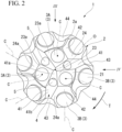
- a drilling bit 1 according to one embodiment of the present invention will be described with reference to the drawings.
- the drilling bit 1 of the present embodiment is connected to a drilling device, such as a drifter, via an extension rod (not shown), and is used to drill the ground or bedrock, that is, to form a drilling hole.
- a drilling device such as a drifter
- an extension rod not shown
- the drilling bit 1 includes a columnar bit body 2 centered on a tool central axis O, and a columnar button (drilling tip) 3, a blow hole 5, and a discharge flow path 4 that are disposed on, among both end parts (a first end part 2a and a second end part 2b) of the bit body 2, the first end part 2a and that are provided at rotationally symmetric positions centered on a tip central axis C.
- a direction in which the tool central axis O of the bit body 2 extends is referred to as a tool axial direction.
- a direction from the second end part 2b toward the first end part 2a of the bit body 2 is referred to as a tip side in the tool axial direction or simply the tip side
- a direction from the first end part 2a toward the second end part 2b is referred to as a rear end side in the tool axial direction or simply the rear end side.
- a direction orthogonal to the tool central axis O is referred to as a tool radial direction.
- a direction approaching the tool central axis O is referred to as an inside in the tool radial direction
- a direction away from the tool central axis O is referred to as an outside in the tool radial direction.
- a direction rotating around the tool central axis O is referred to as a tool circumferential direction.
- a direction in which the drilling bit 1 is rotated by the drilling device and the extension rod during drilling is referred to as a tool rotation direction T
- a rotation direction opposite to this is referred to as an opposite side of the tool rotation direction T or simply counter-tool rotation direction.
- one side in the tool circumferential direction corresponds to the tool rotation direction T
- the other side in the tool circumferential direction corresponds to the counter-tool rotation direction.
- a direction in which the tip central axis C of the button 3 extends is referred to as a tip axial direction.
- One end part of the button 3 protrudes from the surface of the bit body 2, and the other end part thereof is embedded inside the bit body 2.
- a direction from the other end part toward the one end part of the button 3 is referred to as a tip side of the tip axial direction, and a direction from the one end part toward the other end part is referred to as a rear end side of the tip axial direction.
- a direction orthogonal to the tip central axis C is referred to as a tip radial direction.
- a direction rotating around the tip central axis C is referred to as a tip circumferential direction.
- the bit body 2 is made of, for example, steel.
- the bit body 2 has a cylindrical shape extending in the tool axial direction.
- the first end part 2a of the bit body 2 that is, a tip part, has a larger outer diameter than a part other than the tip part.
- the bit body 2 has a female screw hole that is open at an end surface facing the rear end side in the tool axial direction, that is, at a rear end surface, and that extends coaxially in the tool axial direction.
- the female screw hole is disposed in a part other than the first end part 2a of the bit body 2, that is, in a part other than the tip part. With this configuration, it can also be said that the bit body 2 has a bottomed cylindrical shape that is open to the rear end side in the tool axial direction.
- a male screw at a tip part of the extension rod is screwed into the female screw hole of the bit body 2.
- a rotational force around the tool central axis O, and a thrust force and an impact force toward the tip side in the tool axial direction are transmitted from the drilling device to the bit body 2 via the extension rod.
- the drilling bit 1 can advance while crushing the ground or bedrock to form a drilling hole.
- a fluid such as water or compressed air, is supplied to the inside of the bit body 2 (into the female screw hole) via the extension rod or the like having a flow path therein.
- the bit body 2 has a tip surface 21 and an outer peripheral surface 22.
- the tip surface 21 has a face surface 23 facing the tip side in the tool axial direction, and a gauge surface 24 that is disposed outward in the tool radial direction from the face surface 23 and that is located on the rear end side in the tool axial direction while extending outward in the tool radial direction. That is, the gauge surface 24 faces the tip side in the tool axial direction and the outside in the tool radial direction.
- the face surface 23 has a plurality of front surfaces 23a arranged in the tool circumferential direction.
- three front surfaces 23a are provided side by side along the face surface 23 at intervals of 120° in the tool circumferential direction about the tool central axis O.
- the front surface 23a is a plane expanding in a direction perpendicular to the tool central axis O.
- a circular mounting hole (not shown) is open in each front surface 23a. Each mounting hole extends in a direction orthogonal to the front surface 23a, that is, in parallel with the tool central axis O (in the tool axial direction).
- the gauge surface 24 has a plurality of gauge surfaces (bearing surfaces) 24a arranged in the tool circumferential direction.
- six gauge surfaces 24a are provided side by side along the gauge surface 24 in the tool circumferential direction at intervals of approximately 60°.
- the gauge surface 24a is a plane facing the tip side in the tool axial direction and the outside in the tool radial direction (that is, facing a middle direction between the tip side in the tool axial direction and the outside in the tool radial direction).
- the gauge surface 24a is an inclined surface located on the rear end side in the tool axial direction while extending toward one side in the tool circumferential direction, that is, in the tool rotation direction T.
- the gauge surface 24a is also an inclined surface located inward in the tool radial direction while extending in the tool rotation direction T.
- a circular mounting hole (not shown) is open in each gauge surface 24a.
- Each mounting hole extends in a direction orthogonal to the gauge surface 24a, that is, in a direction inclined with respect to the tool central axis O. Specifically, a central axis of each mounting hole and the tool central axis O are at a skew position.
- a tip part of the outer peripheral surface 22 has a larger outer diameter than the part other than the tip part.
- the tip part of the outer peripheral surface 22 has a tapered shape in which the outer diameter increases while extending toward the tip side in the tool axial direction.
- the tip part of the outer peripheral surface 22 is connected to an outer end part of the gauge surface 24 in the tool radial direction.
- the button 3 is made of, for example, cemented carbide.
- the button 3 may be coated with a hard layer made of sintered polycrystalline diamond or the like at the tip part in the tip axial direction.
- the button 3 protrudes from the tip surface 21 of the bit body 2.
- a plurality of the buttons 3 are provided on the tip surface 21.
- Each button 3 is fixed to each mounting hole of the front surface 23a and the gauge surface 24a by interference fitting, such as press fitting or shrink fitting, or by brazing.
- the tip central axis C of each button 3 extends in a direction orthogonal to the front surface 23a or the gauge surface 24a on which each button 3 is disposed.
- the tip part of the button 3 in the tip axial direction protrudes from the tip surface 21 of the bit body 2 and is exposed to the outside.
- a part of the button 3 other than the tip part in the tip axial direction is embedded into the mounting hole.
- the tip part of the button 3 in the tip axial direction has an outer diameter that decreases while extending toward the tip side in the tip axial direction.
- the part of the button 3 other than the tip part in the tip axial direction has a cylindrical shape with a constant outer diameter along the tip axial direction.
- the button 3 of the present embodiment is a so-called spike tip having a substantially conical tip part in the tip axial direction.
- the button 3 has a convexly curved impact edge 3a disposed at the tip part in the tip axial direction, and a tapered part 3b disposed at the tip part in the tip axial direction and located on the rear end side in the tip axial direction with respect to the impact edge 3a.
- the impact edge 3a is located at the leading tip of the button 3 in the tip axial direction.
- the impact edge 3a has a substantially hemispherical shape.
- the radius of curvature of the impact edge 3a is less than 1/2 of the outer diameter dimension of the button 3 (diameter dimension in the tip radial direction).
- the outer diameter dimension of the button 3 indicates an outer diameter dimension of the maximum diameter part of the button 3 and, specifically, is an outer diameter dimension of the part (the cylindrical part) of the button 3 other than the tip part.
- the tapered part 3b is connected to a rear end part of the impact edge 3a in the tip axial direction.
- the tapered part 3b has a tapered shape in which the outer diameter increases while extending toward the rear end side in the tip axial direction.
- the plurality of buttons 3 include a face tip 3A disposed on the face surface 23 and a gauge tip 3B disposed on the gauge surface 24.
- the outer diameter dimension of the gauge tip 3B is larger than the outer diameter dimension of the face tip 3A.
- an amount of protrusion of the gauge tip 3B in which the tip part thereof in the tip axial direction protrudes from the gauge surface 24 is larger than an amount of protrusion of the face tip 3A in which the tip part thereof in the tip axial direction protrudes from the face surface 23.
- a plurality of the face tips 3A are provided on the face surface 23. That is, the plurality of buttons 3 include the plurality of face tips 3A.
- the plurality of buttons 3 include the plurality of face tips 3A.
- three face tips 3A are provided side by side on the face surface 23 in the tool circumferential direction.
- the face tip 3A is provided on each front surface 23a.
- one face tip 3A is disposed for one front surface 23a.
- the tip central axis C of the face tip 3A extends in the tool axial direction.
- a plurality of the gauge tips 3B are provided on the gauge surface 24. That is, the plurality of buttons 3 include the plurality of gauge tips 3B.
- the plurality of buttons 3 include the plurality of gauge tips 3B.
- six gauge tips 3B are provided side by side on the gauge surface 24 in the tool circumferential direction.
- the gauge tip 3B is provided on each gauge surface 24a.
- one gauge tip 3B is disposed for one gauge surface 24a.
- the tip central axis C of the gauge tip 3B extends inward in the tool radial direction while extending toward the rear end side in the tool axial direction.
- the tip central axis C of the gauge tip 3B extends toward the opposite side of the tool rotation direction T in the tool circumferential direction while extending toward the rear end side in the tool axial direction.
- the blow hole 5 extends inside the bit body 2 and is open at the tip surface 21.
- the blow hole 5 has a circular hole shape.
- the blow hole 5 is located inward in the tool radial direction while extending from the tip surface 21 of the bit body 2 toward the rear end side in the tool axial direction. That is, the blow hole 5 extends obliquely with respect to the tool central axis O.
- the blow hole 5 communicates with the inside of the female screw hole of the bit body 2.
- the blow hole 5 When viewed from the tool axial direction, the blow hole 5 is located inward in the tool radial direction or overlaps with respect to the rotational trajectory (not shown) of the face tip 3A around the tool central axis O.
- the rotational trajectory of the face tip 3A around the tool central axis O and the blow hole 5 overlap with each other.
- a plurality of the blow holes 5 are provided.
- three blow holes 5 are provided side by side in the tool circumferential direction, and each blow hole 5 is formed between two adjacent face tips 3A.
- the discharge flow path 4 is disposed from the tip surface 21 over the outer peripheral surface 22 of the bit body 2.
- the discharge flow path 4 extends from the tip surface 21 of the bit body 2 over the tip part of the outer peripheral surface 22.
- a fluid is supplied from the inside of the bit body 2 to the discharge flow path 4 through the blow hole 5.
- the discharge flow path 4 is a flow path for sending cuttings to the rear end side of the bit body 2 by causing the cuttings generated by crushing the ground or bedrock by the button 3 to flow to the outer peripheral surface 22 together with the fluid from the tip surface 21 of the bit body 2.
- the discharge flow path 4 has a first flow path 41, a second flow path 42, a third flow path 43, and a fourth flow path 44.
- the discharge flow path 4 has a plurality of sets of the first flow path 41, the second flow path 42, the third flow path 43, and the fourth flow path 44.
- three sets of the first flow path 41, the second flow path 42, the third flow path 43, and the fourth flow path 44 are provided side by side in the tool circumferential direction. That is, a plurality of first flow paths 41, a plurality of second flow paths 42, a plurality of third flow paths 43, and a plurality of fourth flow paths 44 are each (three each) provided side by side in the tool circumferential direction.
- the first flow path 41 has a groove shape located on the tip surface 21 and extending in the tool radial direction, and the blow hole 5 is open in the middle of the first flow path 41.
- the first flow path 41 is disposed in the tool radial direction between a pair of face tips 3A and 3A adjacent in the tool circumferential direction and between a pair of gauge tips 3B and 3B adjacent in the tool circumferential direction.
- the first flow path 41 extends in the tool radial direction between a pair of front surfaces 23a and 23a adjacent in the tool circumferential direction and between a pair of gauge surfaces 24a and 24a adjacent in the tool circumferential direction.
- the first flow path 41 is located on the rear end side in the tool axial direction while extending outward in the tool radial direction.
- a groove bottom of the first flow path 41 extends linearly in a vertical cross-sectional view including the tool central axis O.
- the tip central axis C of a predetermined button 3 adjacent to the first flow path 41 in the tool circumferential direction is away from the first flow path 41 in the tool circumferential direction while extending toward the rear end side in the tool axial direction.
- the tip central axis C of a predetermined gauge tip 3B adjacent to the first flow path 41 in the counter-tool rotation direction is away from the first flow path 41 in the counter-tool rotation direction while extending toward the rear end side in the tool axial direction.
- the first flow path 41 has a flow rate increasing part 41a and a flow velocity increasing part 41b.
- the flow rate increasing part 41a is disposed on an inner part of the first flow path 41 in the tool radial direction.
- the flow rate increasing part 41a has a groove width that widens while extending outward in the tool radial direction.
- the blow hole 5 is open at the flow rate increasing part 41a.
- the flow velocity increasing part 41b is disposed on an outer part of the first flow path 41 in the tool radial direction.
- the flow velocity increasing part 41b has a groove width that narrows while extending outward in the tool radial direction.
- the flow velocity increasing part 41b is disposed outward in the tool radial direction from the blow hole 5.
- the flow velocity increasing part 41b has a pair of groove walls facing each other in the tool circumferential direction.
- a height in the tool axial direction of one groove wall that is located at an end part of the flow velocity increasing part 41b in the counter-tool rotation direction to face the tool rotation direction T is lower than a height in the tool axial direction of the other groove wall that is located at an end part of the flow velocity increasing part 41b in the tool rotation direction T to face the counter-tool rotation direction. Therefore, some of the fluid flowing through the flow velocity increasing part 41b flows over the one groove wall onto the gauge surface 24a adjacent to the flow velocity increasing part 41b in the counter-tool rotation direction.
- the plurality of first flow paths 41 are connected to each other via an inner end part of each first flow path 41 in the tool radial direction.
- the inner end parts of the flow rate increasing parts 41a of the three first flow paths 41 in the tool radial direction are directly connected to each other.
- the plurality of first flow paths 41 communicate with each other through the tool central axis O.
- the second flow path 42 is located outward in the tool radial direction from the blow hole 5 on the tip surface 21 to communicate with the first flow path 41, and extends in the tool circumferential direction.
- the second flow path 42 extends from a connection part with the first flow path 41 toward at least the opposite side of the tool rotation direction T in the tool circumferential direction.
- the second flow path 42 includes the gauge surface 24a adjacent to the flow velocity increasing part 41b of the first flow path 41 in the counter-tool rotation direction. That is, the second flow path 42 is located on the gauge surface 24a and extends from the connection part with the first flow path 41 toward the other side in the tool circumferential direction, that is, in the counter-tool rotation direction.
- the second flow path 42 may extend across a plurality (two) of gauge surfaces 24a located between a pair of first flow paths 41 and 41 adjacent in the tool circumferential direction.
- the third flow path 43 has a groove shape located on the outer peripheral surface 22 and extending in the tool axial direction, and is connected to the outer end part of the first flow path 41 in the tool radial direction.
- the third flow path 43 is disposed at the tip part of the outer peripheral surface 22, and the tip part of the third flow path 43 in the tool axial direction is open at the tip surface 21.
- the third flow path 43 is connected to the outer end part of the flow velocity increasing part 41b in the tool radial direction and is open at the gauge surface 24.
- the third flow path 43 is located between the pair of gauge tips 3B and 3B in the tool circumferential direction.
- the groove width of the third flow path 43 is greater than or equal to the groove width of the first flow path 41.
- the groove bottom of the third flow path 43 is located outward in the tool radial direction while extending toward the rear end side in the tool axial direction. That is, the groove depth of the third flow path 43 becomes shallower while extending toward the rear end side in the tool axial direction.
- the fourth flow path 44 has a groove shape located on the outer peripheral surface 22 and extending in the tool axial direction, and communicates with the second flow path 42.
- the fourth flow path 44 is disposed at the tip part of the outer peripheral surface 22, and the tip part of the fourth flow path 44 in the tool axial direction is open at the tip surface 21.
- the fourth flow path 44 is open at the gauge surface 24.
- the fourth flow path 44 is located between the pair of gauge tips 3B and 3B in the tool circumferential direction.
- the fourth flow path 44 is located in the counter-tool rotation direction of the first flow path 41 and the third flow path 43.
- the groove width of the fourth flow path 44 is greater than or equal to the groove width of the first flow path 41.
- the groove width of the fourth flow path 44 and the groove width of the third flow path 43 are substantially the same as each other.
- the groove bottom of the fourth flow path 44 is located outward in the tool radial direction while extending toward the rear end side in the tool axial direction. That is, the groove depth of the fourth flow path 44 becomes shallower while extending toward the rear end side in the tool axial direction.
- the discharge flow path 4 has the first flow path 41 extending in the tool radial direction and the second flow path 42 extending in the tool circumferential direction, a fluid can be spread over a wide range of the tip surface 21 of the bit body 2.
- the second flow path 42 is located outward in the tool radial direction from the blow hole 5. Therefore, the fluid flowing out from the blow hole 5 into the first flow path 41 flows along the first flow path 41 in the tool radial direction, and then flows into the second flow path 42 to also flow in the tool circumferential direction. In this way, the fluid flowing out from the blow hole 5 into the first flow path 41 first flows outward in the tool radial direction, so that a decrease in the flow velocity of the fluid is restrained and the force pushing out cuttings toward the rear end side of the bit body 2 is stably increased. Accordingly, it is possible to efficiently and stably discharge cuttings.
- the present embodiment since cuttings can be efficiently discharged, the friability of the button 3, that is, the drilling performance, is well maintained. Specifically, for example, the present embodiment restrains the defect such as secondary crushing of cuttings caused by the crushed cuttings remaining at the tip of the bit as in the conventional art. Therefore, the drilling speed can be improved, and the drilling distance per unit time can be extended. As a result, it is possible to extend the time (distance) in which the drilling bit 1 can drill before the drilling bit reaches its fatigue limit, that is, it is possible to extend the tool life.
- the second flow path 42 extends from the connection part with the first flow path 41 toward at least the opposite side of the tool rotation direction T in the tool circumferential direction.
- the discharge flow path 4 has the third flow path 43 extending in the tool axial direction, and the fluid flowing outward in the tool radial direction through the first flow path 41 flows to the rear end side of the bit body 2 through the third flow path 43. Since a decrease in the flow velocity of the fluid flowing toward the rear end side of the bit body 2 in the discharge flow path 4 is restrained, the force pushing out cuttings toward the rear end side is well maintained, and the dischargeability of cuttings is stably enhanced.
- the rotational trajectory (not shown) of the face tip 3A around the tool central axis O overlaps with at least a part of the blow hole 5.
- the blow hole 5 is located inward in the tool radial direction from the rotational trajectory of the face tip 3A around the tool central axis O.
- the face tip 3A restrains the fluid flowing out from the blow hole 5 from flowing into the tool circumferential direction immediately after the flow-out. Therefore, the fluid flowing from the blow hole 5 in the tool radial direction flows more stably, and the flow velocity of the fluid is increased.
- the gauge surface (bearing surface) 24a on which the gauge tip 3B is provided is located on the rear end side in the tool axial direction while extending toward one side (in the tool rotation direction T) in the tool circumferential direction, and the second flow path 42 is located on the gauge surface 24a and extends from the connection part with the first flow path 41 toward the other side in the tool circumferential direction (in the counter-tool rotation direction).
- the gauge surface 24a on which the gauge tip 3B is disposed also functions as the second flow path 42, the above-described effect of the present embodiment can be obtained while simplifying the structure of the tip surface 21 of the bit body 2.
- the tip central axis C of a predetermined button 3 adjacent to the first flow path 41 in the tool circumferential direction is away from the first flow path 41 in the tool circumferential direction while extending toward the rear end side in the tool axial direction.
- the above configuration is employed, so that a large wall thickness is ensured between the predetermined button 3 (gauge tip 3B) adjacent to the first flow path 41 and the first flow path 41, and the button 3 is restrained from falling off from the bit body 2 because of the wear in the vicinity of the first flow path 41.
- the tip central axis C of the gauge tip 3B extends toward the opposite side of the tool rotation direction T in the tool circumferential direction while extending toward the rear end side in the tool axial direction.
- the gauge tip 3B can receive and relax a bending stress applied onto the gauge tip 3B due to the rotational force in the tool rotation direction T as a compressive stress in the tip axial direction. Therefore, breakage of the gauge tip 3B or the like is restrained.
- the radius of curvature of the impact edge 3a of the button 3 is less than 1/2 of the outer diameter (diameter) dimension of the part of the button 3 other than the tip part.
- the button 3 is a so-called spike tip or the like and the tip part of the button 3 is convexly formed, the drilling speed can be further increased.
- the button 3 has a sharp shape, so that a space for the fluid to flow in the vicinity of the tip part of the button 3 is ensured, and the dischargeability of cuttings can be further enhanced.
- the discharge flow path 4 has the fourth flow path 44 extending in the tool axial direction, and the fluid flowing through the second flow path 42 flows to the rear end side of the bit body 2 through the fourth flow path 44. Therefore, the dischargeability of cuttings can be further enhanced.
- the first flow path 41 has the flow velocity increasing part 41b, and the flow velocity increasing part 41b is disposed outward in the tool radial direction from the blow hole 5 and has a groove width that narrows while extending outward in the tool radial direction.
- the fluid flowing out from the blow hole 5 into the first flow path 41 flows outward in the tool radial direction through the flow velocity increasing part 41b, so that the flow velocity is further increased. Therefore, the dischargeability of cuttings can be stably enhanced.
- the first flow path 41 has the flow rate increasing part 41a
- the flow rate increasing part 41a has a groove width that widens while extending outward in the tool radial direction
- the blow hole 5 is open at the flow rate increasing part 41a.
- the fluid immediately after flowing out from the blow hole 5 into the flow rate increasing part 41a tends to flow in a direction in which the groove width is wide, that is, outward in the tool radial direction. That is, since, in the fluid flowing out from the blow hole 5 into the flow rate increasing part 41a, a flow rate of a fluid flowing outward in the tool radial direction is larger than a flow rate of a fluid flowing inward in the tool radial direction, the fluid as a whole tends to flow outward in the tool radial direction. Therefore, the fluid in the first flow path 41 can stably flow outward in the tool radial direction, and the dischargeability of cuttings can be enhanced.
- the plurality of first flow paths 41 are provided side by side in the tool circumferential direction, and the plurality of first flow paths 41 are connected to each other via the inner end part of each first flow path 41 in the tool radial direction.
- the dischargeability of cuttings can be stably enhanced even in the vicinity of the center part (on the tool central axis O) of the tip surface 21 of the bit body 2.
- the tip central axis C of the button 3 extends in a direction orthogonal to the front surface 23a or the gauge surface 24a on which each button 3 is disposed.
- each of the bearing surfaces 23a and 24a can be used as a reference to accurately perform the re-grinding.
- FIGS. 5 to 8 show a modification example of the drilling bit 1 described in the above-described embodiment.
- the discharge flow path 4 of the drilling bit 1 has a connection flow path 45 that is connected to the inner end parts of the plurality of first flow paths 41 in the tool radial direction.
- the connection flow path 45 has a recessed shape recessed from the tip surface 21 of the bit body 2 toward the rear end side in the tool axial direction, and is located on the tool central axis O.
- the connection flow path 45 allows the first flow paths 41 to communicate with each other.
- the front surface 23a is an inclined surface located on the rear end side in the tool axial direction while extending toward one side in the tool circumferential direction, that is, in the tool rotation direction T.
- the tip central axis C of the face tip 3A extends toward the opposite side of the tool rotation direction T in the tool circumferential direction while extending toward the rear end side in the tool axial direction.
- the face tip 3A can receive and relax a bending stress applied onto the face tip 3A due to the rotational force in the tool rotation direction T as a compressive stress in the tip axial direction. Therefore, breakage of the face tip 3A or the like is restrained.
- the tip central axis C of a predetermined face tip 3A adjacent to the first flow path 41 in the counter-tool rotation direction is away from the first flow path 41 in the counter-tool rotation direction while extending toward the rear end side in the tool axial direction. That is, the tip central axis C of a predetermined button 3 adjacent to the first flow path 41 in the tool circumferential direction is away from the first flow path 41 in the tool circumferential direction while extending toward the rear end side in the tool axial direction.
- the above configuration is employed, so that a large wall thickness is ensured between the predetermined button 3 (face tip 3A) adjacent to the first flow path 41 and the first flow path 41, and the button 3 is restrained from falling off from the bit body 2 because of the wear in the vicinity of the first flow path 41.
- the second flow path 42 of the discharge flow path 4 may be located not only on the gauge surface 24a but also on a part (the outer end part in the tool radial direction) of the front surface 23a.
- one face tip 3A is disposed for one front surface 23a and one gauge tip 3B is disposed for one gauge surface 24a, but the present invention is not limited to this.
- a plurality of face tips 3A may be disposed for one front surface 23a, or a plurality of gauge tips 3B may be disposed for one gauge surface 24a.
- one side in the tool circumferential direction corresponds to the tool rotation direction T and the other side in the tool circumferential direction corresponds to the counter-tool rotation direction, but the present invention is not limited to this.
- One side in the tool circumferential direction may correspond to the counter-tool rotation direction, and the other side in the tool circumferential direction may correspond to the tool rotation direction T.
- the button 3 is a spike tip, but the present invention is not limited to this.
- the button 3 may be, for example, a so-called ballistic tip having a cannonball-shaped tip part.
- the radius of curvature of the impact edge 3a is less than 1/2 of the outer diameter dimension of the button 3, but, for example, in a cross-sectional view inclined with respect to the tip central axis C, the radius of curvature of the impact edge 3a may be less than 1/2 of the outer diameter dimension of the button 3.
- the present invention may combine the configurations described in the above-described embodiment, modification example, and the like without departing from the gist of the present invention, and addition, omission, replacement, and other changes to the configuration are possible. Further, the present invention is not limited by the above-described embodiment and the like, and is limited only by the scope of the claims.
- the present invention has industrial applicability.
Landscapes
- Engineering & Computer Science (AREA)
- Geology (AREA)
- Life Sciences & Earth Sciences (AREA)
- Mining & Mineral Resources (AREA)
- Physics & Mathematics (AREA)
- Environmental & Geological Engineering (AREA)
- Fluid Mechanics (AREA)
- Mechanical Engineering (AREA)
- General Life Sciences & Earth Sciences (AREA)
- Geochemistry & Mineralogy (AREA)
- Earth Drilling (AREA)
- Inorganic Insulating Materials (AREA)
- Surgical Instruments (AREA)
- Polishing Bodies And Polishing Tools (AREA)
Applications Claiming Priority (2)
| Application Number | Priority Date | Filing Date | Title |
|---|---|---|---|
| JP2020180553A JP7565753B2 (ja) | 2020-10-28 | 2020-10-28 | 掘削ビット |
| PCT/JP2021/038580 WO2022091865A1 (fr) | 2020-10-28 | 2021-10-19 | Trépan de forage |
Publications (3)
| Publication Number | Publication Date |
|---|---|
| EP4239158A1 true EP4239158A1 (fr) | 2023-09-06 |
| EP4239158A4 EP4239158A4 (fr) | 2024-08-21 |
| EP4239158B1 EP4239158B1 (fr) | 2026-04-15 |
Family
ID=81383737
Family Applications (1)
| Application Number | Title | Priority Date | Filing Date |
|---|---|---|---|
| EP21885984.1A Active EP4239158B1 (fr) | 2020-10-28 | 2021-10-19 | Trépan de forage |
Country Status (8)
| Country | Link |
|---|---|
| US (1) | US12163380B2 (fr) |
| EP (1) | EP4239158B1 (fr) |
| JP (1) | JP7565753B2 (fr) |
| KR (1) | KR20230095081A (fr) |
| AU (1) | AU2021370409A1 (fr) |
| CA (1) | CA3199458A1 (fr) |
| MX (1) | MX2023004769A (fr) |
| WO (1) | WO2022091865A1 (fr) |
Families Citing this family (1)
| Publication number | Priority date | Publication date | Assignee | Title |
|---|---|---|---|---|
| CN119914177A (zh) | 2023-10-30 | 2025-05-02 | 肯纳金属印度有限公司 | 钻土工具 |
Family Cites Families (12)
| Publication number | Priority date | Publication date | Assignee | Title |
|---|---|---|---|---|
| DE3510048C1 (de) * | 1985-03-20 | 1986-04-10 | Siegfried 5883 Kierspe Treitz | Schlagbohrkrone fuer Gesteinsbohrmaschinen |
| GB2277760B (en) * | 1993-05-08 | 1996-05-29 | Camco Drilling Group Ltd | Improvements in or relating to rotary drill bits |
| US7455126B2 (en) * | 2004-05-25 | 2008-11-25 | Shell Oil Company | Percussive drill bit, drilling system comprising such a drill bit and method of drilling a bore hole |
| PL2592216T3 (pl) * | 2011-11-11 | 2019-05-31 | Sandvik Intellectual Property | Bit wiertniczy do narzędzia do wiercenia w skałach i narzędzie do wiercenia w skałach |
| EP2902583B1 (fr) | 2014-01-31 | 2017-04-12 | Sandvik Intellectual Property AB | Trépan de forage de roche à percussion avec rainures à affleurement |
| EP2990589B1 (fr) * | 2014-08-25 | 2017-05-03 | Sandvik Intellectual Property AB | Trépan à face de coupe en retrait |
| EP3059383B1 (fr) | 2015-02-19 | 2017-12-27 | Sandvik Intellectual Property AB | Trépan pour améliorer le transport des déblais de forage |
| JP6606848B2 (ja) | 2015-04-03 | 2019-11-20 | 三菱マテリアル株式会社 | 掘削工具 |
| WO2019002436A1 (fr) * | 2017-06-30 | 2019-01-03 | Shell Internationale Research Maatschappij B.V. | Train de tiges rotatif orientable |
| PL3617439T3 (pl) | 2018-08-30 | 2021-12-06 | Sandvik Mining And Construction Tools Ab | Wiertnicze narzędzie z zakrzywionymi rowkami dla szlamu |
| JP7213692B2 (ja) | 2019-01-09 | 2023-01-27 | 旭ダイヤモンド工業株式会社 | 掘削用ビット |
| JP7226065B2 (ja) | 2019-04-23 | 2023-02-21 | 株式会社豊田自動織機 | 火花点火式内燃機関の気流制御装置 |
-
2020
- 2020-10-28 JP JP2020180553A patent/JP7565753B2/ja active Active
-
2021
- 2021-10-19 US US18/033,421 patent/US12163380B2/en active Active
- 2021-10-19 CA CA3199458A patent/CA3199458A1/fr active Pending
- 2021-10-19 KR KR1020237014273A patent/KR20230095081A/ko active Pending
- 2021-10-19 WO PCT/JP2021/038580 patent/WO2022091865A1/fr not_active Ceased
- 2021-10-19 MX MX2023004769A patent/MX2023004769A/es unknown
- 2021-10-19 EP EP21885984.1A patent/EP4239158B1/fr active Active
- 2021-10-19 AU AU2021370409A patent/AU2021370409A1/en active Pending
Also Published As
| Publication number | Publication date |
|---|---|
| US12163380B2 (en) | 2024-12-10 |
| US20230392448A1 (en) | 2023-12-07 |
| JP7565753B2 (ja) | 2024-10-11 |
| JP2022071528A (ja) | 2022-05-16 |
| AU2021370409A1 (en) | 2023-06-08 |
| EP4239158B1 (fr) | 2026-04-15 |
| CA3199458A1 (fr) | 2022-05-05 |
| KR20230095081A (ko) | 2023-06-28 |
| WO2022091865A1 (fr) | 2022-05-05 |
| AU2021370409A9 (en) | 2024-09-26 |
| MX2023004769A (es) | 2023-06-09 |
| EP4239158A4 (fr) | 2024-08-21 |
Similar Documents
| Publication | Publication Date | Title |
|---|---|---|
| KR100949695B1 (ko) | 충격식 드릴 비트와 그에 사용되는 버튼 | |
| EP3184729B1 (fr) | Outil d'excavation | |
| EP2975209B1 (fr) | Outil de creusage | |
| AU2015309212B2 (en) | Drill bit with recessed cutting face | |
| CN103906885B (zh) | 具有凹陷球齿的钻头及与该钻头一起使用的岩钻工具 | |
| KR101942131B1 (ko) | 암반 드릴링 공구용 드릴 비트 및 암반 드릴링 공구 | |
| JP4954542B2 (ja) | 掘削ロッド、掘削ビット及び掘削工具 | |
| US12163380B2 (en) | Drilling bit | |
| EP2921639A1 (fr) | Trépan à percussion avec de multiples ensembles d'inserts de coupe avant | |
| US6655480B1 (en) | Cutting insert for percussion drill bit | |
| RU2652726C1 (ru) | Лопастное долото с износостойкой цилиндрической режущей структурой | |
| WO2016158879A1 (fr) | Outil d'excavation | |
| JP2014196615A (ja) | 掘削ビット及びこれに用いられる掘削チップ | |
| JP2014185477A (ja) | 掘削ビット | |
| JP2014185478A (ja) | 掘削ビット |
Legal Events
| Date | Code | Title | Description |
|---|---|---|---|
| STAA | Information on the status of an ep patent application or granted ep patent |
Free format text: STATUS: THE INTERNATIONAL PUBLICATION HAS BEEN MADE |
|
| PUAI | Public reference made under article 153(3) epc to a published international application that has entered the european phase |
Free format text: ORIGINAL CODE: 0009012 |
|
| STAA | Information on the status of an ep patent application or granted ep patent |
Free format text: STATUS: REQUEST FOR EXAMINATION WAS MADE |
|
| 17P | Request for examination filed |
Effective date: 20230425 |
|
| AK | Designated contracting states |
Kind code of ref document: A1 Designated state(s): AL AT BE BG CH CY CZ DE DK EE ES FI FR GB GR HR HU IE IS IT LI LT LU LV MC MK MT NL NO PL PT RO RS SE SI SK SM TR |
|
| DAV | Request for validation of the european patent (deleted) | ||
| DAX | Request for extension of the european patent (deleted) | ||
| REG | Reference to a national code |
Free format text: PREVIOUS MAIN CLASS: E21B0010380000 Ref country code: DE Ref legal event code: R079 Ref document number: 602021052324 Country of ref document: DE Free format text: PREVIOUS MAIN CLASS: E21B0010380000 Ipc: E21B0010600000 |
|
| A4 | Supplementary search report drawn up and despatched |
Effective date: 20240722 |
|
| RIC1 | Information provided on ipc code assigned before grant |
Ipc: E21B 10/60 20060101AFI20240716BHEP |
|
| GRAP | Despatch of communication of intention to grant a patent |
Free format text: ORIGINAL CODE: EPIDOSNIGR1 |
|
| STAA | Information on the status of an ep patent application or granted ep patent |
Free format text: STATUS: GRANT OF PATENT IS INTENDED |
|
| INTG | Intention to grant announced |
Effective date: 20251202 |
|
| GRAS | Grant fee paid |
Free format text: ORIGINAL CODE: EPIDOSNIGR3 |
|
| GRAA | (expected) grant |
Free format text: ORIGINAL CODE: 0009210 |
|
| STAA | Information on the status of an ep patent application or granted ep patent |
Free format text: STATUS: THE PATENT HAS BEEN GRANTED |
|
| AK | Designated contracting states |
Kind code of ref document: B1 Designated state(s): AL AT BE BG CH CY CZ DE DK EE ES FI FR GB GR HR HU IE IS IT LI LT LU LV MC MK MT NL NO PL PT RO RS SE SI SK SM TR |
|
| REG | Reference to a national code |
Ref country code: CH Ref legal event code: F10 Free format text: ST27 STATUS EVENT CODE: U-0-0-F10-F00 (AS PROVIDED BY THE NATIONAL OFFICE) Effective date: 20260415 |