EP4239207B1 - Isolierte lagervorrichtung - Google Patents
Isolierte lagervorrichtung Download PDFInfo
- Publication number
- EP4239207B1 EP4239207B1 EP21886188.8A EP21886188A EP4239207B1 EP 4239207 B1 EP4239207 B1 EP 4239207B1 EP 21886188 A EP21886188 A EP 21886188A EP 4239207 B1 EP4239207 B1 EP 4239207B1
- Authority
- EP
- European Patent Office
- Prior art keywords
- axial
- outer ring
- inner peripheral
- cylindrical surface
- peripheral cylindrical
- Prior art date
- Legal status (The legal status is an assumption and is not a legal conclusion. Google has not performed a legal analysis and makes no representation as to the accuracy of the status listed.)
- Active
Links
Images




Classifications
-
- F—MECHANICAL ENGINEERING; LIGHTING; HEATING; WEAPONS; BLASTING
- F16—ENGINEERING ELEMENTS AND UNITS; GENERAL MEASURES FOR PRODUCING AND MAINTAINING EFFECTIVE FUNCTIONING OF MACHINES OR INSTALLATIONS; THERMAL INSULATION IN GENERAL
- F16C—SHAFTS; FLEXIBLE SHAFTS; ELEMENTS OR CRANKSHAFT MECHANISMS; ROTARY BODIES OTHER THAN GEARING ELEMENTS; BEARINGS
- F16C19/00—Bearings with rolling contact, for exclusively rotary movement
- F16C19/02—Bearings with rolling contact, for exclusively rotary movement with bearing balls essentially of the same size in one or more circular rows
- F16C19/04—Bearings with rolling contact, for exclusively rotary movement with bearing balls essentially of the same size in one or more circular rows for radial load mainly
- F16C19/06—Bearings with rolling contact, for exclusively rotary movement with bearing balls essentially of the same size in one or more circular rows for radial load mainly with a single row or balls
-
- F—MECHANICAL ENGINEERING; LIGHTING; HEATING; WEAPONS; BLASTING
- F16—ENGINEERING ELEMENTS AND UNITS; GENERAL MEASURES FOR PRODUCING AND MAINTAINING EFFECTIVE FUNCTIONING OF MACHINES OR INSTALLATIONS; THERMAL INSULATION IN GENERAL
- F16C—SHAFTS; FLEXIBLE SHAFTS; ELEMENTS OR CRANKSHAFT MECHANISMS; ROTARY BODIES OTHER THAN GEARING ELEMENTS; BEARINGS
- F16C19/00—Bearings with rolling contact, for exclusively rotary movement
- F16C19/52—Bearings with rolling contact, for exclusively rotary movement with devices affected by abnormal or undesired conditions
-
- F—MECHANICAL ENGINEERING; LIGHTING; HEATING; WEAPONS; BLASTING
- F16—ENGINEERING ELEMENTS AND UNITS; GENERAL MEASURES FOR PRODUCING AND MAINTAINING EFFECTIVE FUNCTIONING OF MACHINES OR INSTALLATIONS; THERMAL INSULATION IN GENERAL
- F16C—SHAFTS; FLEXIBLE SHAFTS; ELEMENTS OR CRANKSHAFT MECHANISMS; ROTARY BODIES OTHER THAN GEARING ELEMENTS; BEARINGS
- F16C33/00—Parts of bearings; Special methods for making bearings or parts thereof
- F16C33/30—Parts of ball or roller bearings
- F16C33/58—Raceways; Race rings
-
- F—MECHANICAL ENGINEERING; LIGHTING; HEATING; WEAPONS; BLASTING
- F16—ENGINEERING ELEMENTS AND UNITS; GENERAL MEASURES FOR PRODUCING AND MAINTAINING EFFECTIVE FUNCTIONING OF MACHINES OR INSTALLATIONS; THERMAL INSULATION IN GENERAL
- F16C—SHAFTS; FLEXIBLE SHAFTS; ELEMENTS OR CRANKSHAFT MECHANISMS; ROTARY BODIES OTHER THAN GEARING ELEMENTS; BEARINGS
- F16C35/00—Rigid support of bearing units; Housings, e.g. caps, covers
- F16C35/04—Rigid support of bearing units; Housings, e.g. caps, covers in the case of ball or roller bearings
- F16C35/06—Mounting or dismounting of ball or roller bearings; Fixing them onto shaft or in housing
- F16C35/067—Fixing them in a housing
-
- F—MECHANICAL ENGINEERING; LIGHTING; HEATING; WEAPONS; BLASTING
- F16—ENGINEERING ELEMENTS AND UNITS; GENERAL MEASURES FOR PRODUCING AND MAINTAINING EFFECTIVE FUNCTIONING OF MACHINES OR INSTALLATIONS; THERMAL INSULATION IN GENERAL
- F16C—SHAFTS; FLEXIBLE SHAFTS; ELEMENTS OR CRANKSHAFT MECHANISMS; ROTARY BODIES OTHER THAN GEARING ELEMENTS; BEARINGS
- F16C35/00—Rigid support of bearing units; Housings, e.g. caps, covers
- F16C35/04—Rigid support of bearing units; Housings, e.g. caps, covers in the case of ball or roller bearings
- F16C35/06—Mounting or dismounting of ball or roller bearings; Fixing them onto shaft or in housing
- F16C35/07—Fixing them on the shaft or housing with interposition of an element
- F16C35/077—Fixing them on the shaft or housing with interposition of an element between housing and outer race ring
-
- F—MECHANICAL ENGINEERING; LIGHTING; HEATING; WEAPONS; BLASTING
- F16—ENGINEERING ELEMENTS AND UNITS; GENERAL MEASURES FOR PRODUCING AND MAINTAINING EFFECTIVE FUNCTIONING OF MACHINES OR INSTALLATIONS; THERMAL INSULATION IN GENERAL
- F16C—SHAFTS; FLEXIBLE SHAFTS; ELEMENTS OR CRANKSHAFT MECHANISMS; ROTARY BODIES OTHER THAN GEARING ELEMENTS; BEARINGS
- F16C41/00—Other accessories, e.g. devices integrated in the bearing not relating to the bearing function as such
- F16C41/002—Conductive elements, e.g. to prevent static electricity
-
- F—MECHANICAL ENGINEERING; LIGHTING; HEATING; WEAPONS; BLASTING
- F16—ENGINEERING ELEMENTS AND UNITS; GENERAL MEASURES FOR PRODUCING AND MAINTAINING EFFECTIVE FUNCTIONING OF MACHINES OR INSTALLATIONS; THERMAL INSULATION IN GENERAL
- F16C—SHAFTS; FLEXIBLE SHAFTS; ELEMENTS OR CRANKSHAFT MECHANISMS; ROTARY BODIES OTHER THAN GEARING ELEMENTS; BEARINGS
- F16C2202/00—Solid materials defined by their properties
- F16C2202/30—Electric properties; Magnetic properties
- F16C2202/32—Conductivity
-
- F—MECHANICAL ENGINEERING; LIGHTING; HEATING; WEAPONS; BLASTING
- F16—ENGINEERING ELEMENTS AND UNITS; GENERAL MEASURES FOR PRODUCING AND MAINTAINING EFFECTIVE FUNCTIONING OF MACHINES OR INSTALLATIONS; THERMAL INSULATION IN GENERAL
- F16C—SHAFTS; FLEXIBLE SHAFTS; ELEMENTS OR CRANKSHAFT MECHANISMS; ROTARY BODIES OTHER THAN GEARING ELEMENTS; BEARINGS
- F16C2240/00—Specified values or numerical ranges of parameters; Relations between them
- F16C2240/40—Linear dimensions, e.g. length, radius, thickness, gap
-
- F—MECHANICAL ENGINEERING; LIGHTING; HEATING; WEAPONS; BLASTING
- F16—ENGINEERING ELEMENTS AND UNITS; GENERAL MEASURES FOR PRODUCING AND MAINTAINING EFFECTIVE FUNCTIONING OF MACHINES OR INSTALLATIONS; THERMAL INSULATION IN GENERAL
- F16C—SHAFTS; FLEXIBLE SHAFTS; ELEMENTS OR CRANKSHAFT MECHANISMS; ROTARY BODIES OTHER THAN GEARING ELEMENTS; BEARINGS
- F16C2380/00—Electrical apparatus
- F16C2380/26—Dynamo-electric machines or combinations therewith, e.g. electro-motors and generators
Definitions
- the present invention relates to an insulated bearing device in which electric corrosion is prevented.
- an electric motor is used as an engine for driving a vehicle.
- an inverter is used to convert the DC power of the battery into AC power, and, in order to increase the efficiency of the electric motor, the frequency of the AC power supplied to the electric motor is set high.
- an insulated bearing (as disclosed in, e.g., the below-identified Patent Document 1) is generally used.
- Such an insulated bearing includes an outer ring fitted in a housing hole of a housing; an inner ring arranged radially inwardly of, and coaxially with, the outer ring; and a plurality of rolling elements disposed between the outer ring and the inner ring, and an insulating film that provides electrical insulation between the housing and the outer ring is disposed on the surface of the outer ring.
- the magnitude of the alternating electric current increases as the areas of the opposed portions of the metal surfaces of the housing and the outer ring opposed to each other via the insulating film increase, and also increases as the distance between the metal surfaces of the housing and the outer ring opposed to each other via the insulating film decreases.
- Patent Document 1 proposes an insulated bearing in which, as illustrated in Fig. 1(a) of this document, a recess is disposed in the axial central portion of the outer peripheral surface of the outer ring, and an insulating film having a constant thickness is disposed on a surface of the outer ring including the recess.
- the insulating film includes an outer peripheral surface portion extending along the outer periphery of the outer ring; a pair of end surface portions extending along the respective end surfaces of the outer ring on both axial sides thereof; and a pair of chamfers having a circular arc-shaped cross section, and connecting together the outer peripheral surface portion and the respective end surface portions.
- the outer peripheral surface portion of the insulating film has a recessed portion recessed corresponding to the shape of the recess of the outer periphery of the outer ring.
- Patent Document 2 discloses an insulated bearing device according to the preamble of claim 1.
- the present invention provides an insulated bearing device comprising: a housing formed with a housing hole; an outer ring fitted in the housing hole; an inner ring arranged radially inwardly of, and coaxially with, the outer ring; and a plurality of rolling elements mounted between the outer ring and the inner ring, wherein an insulating film that provides electrical insulation between the housing and the outer ring is disposed on a surface of the outer ring, wherein the insulating film comprises: a straight portion extending along an outer periphery of the outer ring and having a constant outer diameter in an axial direction; a pair of end surface portions extending along respective end surfaces of the outer ring on both axial sides of the outer ring; and a pair of chamfers having a circular arc-shaped cross section, and connecting together the straight portion and the respective end surface portions, wherein the housing has, on an inner periphery of the housing hole, an inner peripheral cylindrical surface formed at a position intersecting with axial centerlines of
- the straight portion of the insulating film which extends along the outer periphery of the outer ring, is in contact, not along the entire axial length of the straight portion, but within a range shorter than the entire axial length of the straight portion, with the inner peripheral cylindrical surface of the housing hole. Therefore, the impedance between the housing and the outer ring is higher corresponding to the reduced axial length of the contact range. This effectively reduces the magnitude of the alternating electric current that flows when an AC voltage acts between the housing and the outer ring.
- the portion of the insulating film extending along the outer periphery of the outer ring is a straight portion having a constant outer diameter in the axial direction, and no recess is present in the insulating film, formation of the insulating film is easy, and productivity is excellent.
- the inner peripheral cylindrical surface has one and the other axial ends, said one axial end of the inner peripheral cylindrical surface is axially displaced from one axial end of the straight portion, away from the axial centerlines of the rolling elements, said other axial end of the inner peripheral cylindrical surface is axially displaced from the other axial end of the straight portion toward the axial centerlines of the rolling elements, and the housing has: an axially inner end surface extending radially inwardly from the one axial end of the inner peripheral cylindrical surface, and kept in contact with one of the end surface portions; and a non-contact surface extending radially outwardly from the other axial end of the inner peripheral cylindrical surface.
- the inner peripheral cylindrical surface has one and the other axial ends; wherein said one axial end of the inner peripheral cylindrical surface is axially displaced from one axial end of the straight portion toward the axial centerlines of the rolling elements, said other axial end of the inner peripheral cylindrical surface is axially displaced from the other axial end of the straight portion toward the axial centerlines of the rolling elements, and the housing includes: a first non-contact surface extending radially outwardly from said one axial end of the inner peripheral cylindrical surface; and a second non-contact surface extending radially outwardly from said other axial end of the inner peripheral cylindrical surface.
- the housing may further include: a first auxiliary support portion supporting an outer periphery of the straight portion at a position axially spaced apart from the first non-contact surface; and a second auxiliary support portion supporting the outer periphery of the straight portion at a position axially spaced apart from the second non-contact surface.
- the inner peripheral cylindrical surface is preferably formed such that major-axis ranges of contact ellipses defined by contact between the rolling elements and the outer ring are located within a contact range between the inner peripheral cylindrical surface and the straight portion.
- the straight portion of the insulating film which extends along the outer periphery of the outer ring, is in contact, not along the entire axial length of the straight portion but within a range shorter than the entire axial length of the straight portion, with the inner peripheral cylindrical surface of the housing hole. Therefore, the impedance between the housing and the outer ring is higher by the reduced axial length of the contact range. This effectively reduces the magnitude of the alternating electric current that flows when an AC voltage acts between the housing and the outer ring.
- the portion of the insulating film extending along the outer periphery of the outer ring is a straight portion having a constant outer diameter in the axial direction, and no recess is present in the insulating film, formation of the insulating film is easy, and the productivity is excellent.
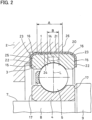
- Fig. 1 illustrates an insulated bearing device according to the first embodiment of the present invention.
- This insulated bearing device includes a housing 2 having a housing hole 1; an outer ring 3 fitted in the housing hole 1; an inner ring 4 arranged radially inwardly of, and coaxially with, the outer ring 3; a plurality of rolling elements 5 disposed between the outer ring 3 and the inner ring 4; a cage 6 that keeps the circumferential distances between the rolling elements 5; and a rotary shaft 7 fitted to the inner ring 4.
- the outer ring 3, the inner ring 4 and the rolling element 5 are all made of metal.
- the rolling elements 5 are balls in the shown example.
- the rotary shaft 7 is the rotary shaft of an electric motor for driving an electric vehicle.
- the rotary shaft 7 includes a small-diameter shaft portion 8 fitted to the inner periphery of the inner ring 4; and a large-diameter shaft portion 9 kept in contact with an axial end surface of the inner ring 4.
- the large-diameter shaft portion 9 has an outer diameter larger than the outer diameter of the small-diameter shaft portion 8.
- the rotary shaft 7 is made of metal.
- the housing 2 is also made of metal.
- the inner ring 4 has, on its outer periphery, an inner ring raceway groove 10 with which the rolling elements 5 come into rolling contact; and inner ring shoulders 11 located on both axial sides of the inner ring raceway groove 10.
- the outer ring 3 also has, on its inner periphery, an outer ring raceway groove 12 with which the rolling elements 5 come into rolling contact; and outer ring shoulders 13 located on both axial sides of the outer ring raceway groove 12.
- the inner ring raceway groove 10 and the outer ring raceway groove 12 are grooves both having a circular arc-shaped cross section.
- the outer ring 3 has, on its outer periphery, a cylindrical surface 14 having a constant outer diameter in the axial direction; and chamfers 16 having a circular arc-shaped cross section, and connecting together the cylindrical surface 14 and the respective end surfaces 15 of the outer ring 3 on both axial sides thereof.
- the cylindrical surface 14 is a complete cylindrical surface in that it is free of a recess.
- the insulating film 20 that provides electrical insulation between the housing 2 and the outer ring 3 is disposed on the surface of the outer ring 3.
- the insulating film 20 may be made of a ceramic material.
- the ceramic material may be, e.g., a metal oxide such as alumina (Al 2 O 3 ), titanium oxide (TiO 2 ) or chromium oxide (Cr 2 O 3 ).
- the insulating film 20 may be made of a resin such as epoxy resin or polyamideimide resin.
- a resin film of, e.g., epoxy resin or polyamideimide resin can be formed by adding a curing agent to the resin and firing the resin.
- the thickness of the insulating film 20 can be set within the range of 0.15 mm to 0.45 mm.
- the insulating film 20 includes a straight portion 21 extending along the outer periphery of the outer ring 3 and having a constant outer diameter in the axial direction; a pair of end surface portions 22 extending along the respective end surfaces 15 of the outer ring 3 on both axial sides thereof; and a pair of chamfers 23 having a circular arc-shaped cross section and connecting together the straight portion 21 and the respective end surface portions 22.
- the outer periphery of the straight portion 21 is a complete cylindrical surface in that it is free of a recess.
- the housing 2 has an inner peripheral cylindrical surface 24, an axially inner end surface 25, and a non-contact surface 26.
- the inner peripheral cylindrical surface 24 is a cylindrical inner surface formed on the inner periphery of the housing hole 1 and having a constant inner diameter in the axial direction.
- the inner peripheral cylindrical surface 24 is formed at a position intersecting with the axial centerlines L of the rolling elements 5.
- the straight portion 21 of the insulating film 20 is fitted to, and in contact with, the inner peripheral cylindrical surface 24.
- One axial end (left end in Fig. 2 ) of the inner peripheral cylindrical surface 24 is axially displaced from one axial end (left end in Fig. 2 ) of the straight portion 21 of the insulating film 20, away from the axial centerlines L of the rolling elements 5 (in the leftward direction in Fig. 2 ).
- the other axial end (right end in Fig. 2 ) of the inner peripheral cylindrical surface 24 is axially displaced from the other axial end (right end in Fig. 2 ) of the straight portion 21 of the insulating film 20 toward the axial centerlines L of the rolling elements 5 (in the leftward direction in Fig. 2 ).
- the axially inner end surface 25 of the housing 2 extends radially inwardly from the one (axial) end (left end in Fig. 2 ) of the inner peripheral cylindrical surface 24.
- the axially inner end surface 25 is in contact with one of the end surface portions 22 of the insulating film 20 (left end surface portion 22 in Fig. 2 ).
- the non-contact surface 26 of the housing 2 extends radially outwardly from the other (axial) end (right end in Fig. 2 ) of the inner peripheral cylindrical surface 24.
- the contact range A between the inner peripheral cylindrical surface 24 and the straight portion 21 has an axial length shorter than the entire axial length of the straight portion 21.
- the inner peripheral cylindrical surface 24 is formed such that, within the contact range A are located the major-axis ranges B of contact ellipses defined by the contact between the rolling elements 5 and the outer ring 3.
- the contact ellipses are elliptical surface contact portions defined by the rolling elements 5 and the outer ring 3 when loads are applied to the rolling elements 5 and the outer ring 3.
- the sizes of the contact ellipses are determined, by the formula of the Hertz theory, based on the longitudinal elastic modulus and Poisson's ratio of the outer ring 3, the longitudinal elastic modulus and Poisson's ratio of the rolling elements 5, the curvature of the surface of the outer ring raceway groove 12, the curvature of the surfaces of the rolling elements 5, and the magnitude of the loads applied to the rolling elements 5 and the outer ring 3.
- the basic static radial load rating can be used as the magnitude of the loads applied to the rolling elements 5 and the outer ring 3.
- the outer ring 3, the inner ring 4 and the rolling elements 5 constitute a deep groove ball bearing.
- This deep groove ball bearing is axially positioned as a whole by positioning, on one axial side, the outer ring 3 with the axial inner end surface 25 of the housing 2, and positioning, on the other axial side, the inner ring 4with the large-diameter shaft portion 9 of the rotary shaft 7.
- the end surface portion 22 of the insulating film 20 disposed on, of the end surfaces 15 of the outer ring 3 on both axial sides thereof, the end surface 15 on the other axial side (right side in Fig. 2 ) is in contact with no member and exposed.
- the end surface 17 on the inner ring 4 on both axial sides thereof is also in contact with no member and exposed.
- an insulating film 20 is disposed that provides electrical insulation between the housing 2 and the outer ring 3, when an AC voltage acts between the housing 2 and the outer ring 3, the housing 2 and the outer ring 3, which are separated from each other by the insulating film 20, repeatedly store and discharge electricity as a capacitor, so that an alternating electric current may flow in the rolling bearing.
- the magnitude of this alternating electric current increases as the impedance between the housing 2 and the outer ring 3 decreases (i.e., as the capacitance between the housing and the outer ring increases).
- the magnitude of the alternating electric current increases with an increase in the areas of the portions of the metal surfaces of the housing 2 and the outer ring 3 that are opposed to each other via the insulating film 20, and also increases with a decrease in the distance between the portions of the metal surfaces of the housing 2 and the outer ring 3 that are opposed to each other via the insulating film 20.
- the axial length of the contact range A between the inner peripheral cylindrical surface 24 and the straight portion 21 is, as illustrated in Fig. 2 , made shorter than the entire axial length of the straight portion 21.
- the straight portion 21 of the insulating film 20, which extends along the outer periphery of the outer ring 3 is in contact, not along the entire axial length of the straight portion 21, but within a range shorter than the entire axial length of the straight portion 21, with the inner peripheral cylindrical surface 24 of the housing hole 1.
- the contact range A between the inner peripheral cylindrical surface 24 and the straight portion 21 are axially shorter than in the arrangement where, as illustrated in Fig. 6 , the straight portion 21 of the insulating film 20 is in contact, along the entire axial length of the straight portion 21, with the inner peripheral cylindrical surface 24 of the housing hole 1, so that the impedance between the housing 2 and the outer ring 3 is higher corresponding to the reduced axial lengths of the contact range A.
- the portion of the insulating film 20 extending along the outer periphery of the outer ring 3 is a straight portion 21 having a constant outer diameter in the axial direction, and no recess is present in the insulating film 20, formation of the insulating film 20 is easy, and the productivity is excellent. Also, the cost is low.
- this insulated bearing device it is possible to increase the impedance between the housing 2 and the outer ring 3 while axially positioning the outer ring 3 with the axially inner end surface 25 of the housing 2.
- Fig. 3 illustrates an insulated bearing device according to the second embodiment of the present invention.
- the elements of the second embodiment corresponding to those of the first embodiment are denoted by the same reference numerals, and their description is omitted.
- a positioning ring 18 is fixed to the small-diameter shaft portion 8 of the rotary shaft 7, while being in contact with one of the end surfaces 17 of the inner ring 4 on both axial sides thereof, i.e., the end surface 17 (left end surface in Fig. 3 ) opposite from the end surface 17 kept in contact with the large-diameter shaft portion 9 of the rotary shaft 7.
- the housing 2 has an inner peripheral cylindrical surface 24, a first non-contact surface 27 and a second non-contact surface 28.
- the inner peripheral cylindrical surface 24 is a cylindrical inner surface formed on the inner periphery of the housing hole 1 and having a constant inner diameter in the axial direction.
- the inner peripheral cylindrical surface 24 is formed at a position intersecting with the axial centerlines L of the rolling elements 5.
- the straight portion 21 of the insulating film 20 is fitted to, while being in contact with, the inner peripheral cylindrical surface 24.
- One axial end (left end in Fig. 3 ) of the inner peripheral cylindrical surface 24 is axially displaced from one axial end (left end in Fig. 3 ) of the straight portion 21 of the insulating film 20 toward the axial centerlines L of the rolling elements 5 (in the rightward direction in Fig. 3 ).
- the other axial end (right end in Fig. 3 ) of the inner peripheral cylindrical surface 24 is axially displaced from the other axial end (right end in Fig. 3 ) of the straight portion 21 of the insulating film 20 toward the axial centerlines L of the rolling elements 5 (in the leftward direction in Fig. 3 ).
- the inner peripheral cylindrical surface 24 has an axial length shorter than the axial length of the straight portion 21 of the insulating film 20.
- the first non-contact surface 27 of the housing 2 extends radially outwardly from the one (axial) end (left end in Fig. 3 ) of the inner peripheral cylindrical surface 24.
- the second non-contact surface 28 of the housing 2 also extends radially outwardly from the other (axial) end (right end in Fig. 3 ) of the inner peripheral cylindrical surface 24.
- the contact range A between the inner peripheral cylindrical surface 24 and the straight portion 21 has an axial length shorter than the entire axial length of the straight portion 21.
- the inner peripheral cylindrical surface 24 is formed such that the major-axis ranges B of contact ellipses defined by the contact between the rolling elements 5 and the outer ring 3 are located within the axial length of the contact range A.
- the outer ring 3, the inner ring 4 and the rolling elements 5 constitute a deep groove ball bearing.
- This deep groove ball bearing is axially positioned as a whole by positioning the inner ring 4 on one axial side thereof, with the positioning ring 18, which is fixed to the small-diameter shaft portion 8 of the rotary shaft 7, and on the other axial side of the inner ring 4, with the large-diameter shaft portion 9 of the rotary shaft 7.
- the end surface portions 22 of the insulating film 20 on the end surfaces 15 of the outer ring 3 on both axial sides thereof are both in contact with no members and exposed.
- the impedance between the housing 2 and the outer ring 3 is high in this insulated bearing device. Therefore, it is possible to effectively reduce the magnitude of the alternating electric current that flows when an AC voltage acts between the housing 2 and the outer ring 3.
- the portion of the insulating film 20 extending along the outer periphery of the outer ring 3 is a straight portion 21 having a constant outer diameter in the axial direction, and no recess is present in the insulating film 20, formation of the insulating film 20 is easy, and the productivity is excellent. Also, the cost is low.
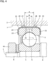
- Fig. 4 illustrates a variation of the insulated bearing device of the second embodiment.
- the housing 2 further includes a first auxiliary support portion 29 supporting the outer periphery of the straight portion 21 at a position axially spaced apart from the first non-contact surface 27; and a second auxiliary support portion 30 supporting the outer periphery of the straight portion 21 at a position axially spaced apart from the second non-contact surface 28.
- the first and second auxiliary support portions 29 and 30 are protrusions disposed on the inner periphery of the housing hole 1 in the shown example.
- Fig. 5 illustrates a variation of the insulated bearing device of the first embodiment.
- the housing 2 is provided with an axially protruding annular protrusion 31 disposed on the axially inner end surface 25, and having a distal end kept in contact with one of the end surface portions 22 of the insulating film 20 (left end surface portion 22).
Landscapes
- Engineering & Computer Science (AREA)
- General Engineering & Computer Science (AREA)
- Mechanical Engineering (AREA)
- Rolling Contact Bearings (AREA)
- Mounting Of Bearings Or Others (AREA)
Claims (5)
- Isolierte Lagervorrichtung, aufweisend:ein Gehäuse (2), das mit einem Gehäuseloch (1) ausgebildet ist;einen Außenring (3), der in das Gehäuseloch (1) eingepasst ist;einen Innenring (4), der radial innerhalb und koaxial zu dem Außenring (3) angeordnet ist; undeine Vielzahl von Wälzkörpern (5), die zwischen dem Außenring (3) und dem Innenring (4) angeordnet sind,wobei ein Isolierfilm (20), der eine elektrische Isolierung zwischen dem Gehäuse (2) und dem Außenring (3) bereitstellt, auf einer Oberfläche des Außenrings (3) angeordnet ist,wobei der Isolierfilm (20) umfasst:einen geraden Abschnitt (21), der sich entlang eines Außenumfangs des Außenrings (3) erstreckt und einen konstanten Außendurchmesser in einer axialen Richtung aufweist;ein Paar Endflächenabschnitte (22), die sich entlang jeweiliger Endflächen (15) des Außenrings (3) auf beiden axialen Seiten des Außenrings (3) erstrecken; undein Paar Abschrägungen (23) mit einem kreisbogenförmigen Querschnitt, die den geraden Abschnitt (21) und die jeweiligen Endflächenabschnitte (22) miteinander verbinden,wobei das Gehäuse (2) an einem Innenumfang des Gehäuselochs (1) eine innere periphere zylindrische Oberfläche (24) aufweist, die an einer Position ausgebildet ist, die sich mit den axialen Mittellinien (L) der Wälzkörper (5) schneidet, und der gerade Abschnitt (21) an der inneren Umfangs-Zylinderfläche (24) angebracht ist und mit dieser in Kontakt steht,wobei die isolierte Lagervorrichtung dadurch gekennzeichnet ist, dasseine Kontaktfläche (A) zwischen der inneren peripheren zylindrischen Oberfläche (24) und dem geraden Abschnitt (21) eine axiale Länge aufweist, die kürzer ist als eine gesamte axiale Länge des geraden Abschnitts (21).
- Isolierte Lagervorrichtung nach Anspruch 1, wobei die innere periphere zylindrische Oberfläche (24) ein und das andere axiale Ende aufweist,wobei das eine axiale Ende der inneren peripheren zylindrischen Oberfläche (24) axial von einem axialen Ende des geraden Abschnitts (21) weg von den axialen Mittellinien (L) der Wälzkörper (5) versetzt ist,wobei das andere axiale Ende der inneren peripheren zylindrischen Oberfläche (24) axial von dem anderen axialen Ende des geraden Abschnitts (21) zu den axialen Mittellinien (L) der Wälzkörper (5) versetzt ist, undwobei das Gehäuse (2) Folgendes aufweist:eine axial innere Endfläche (25), die sich von dem einen axialen Ende der inneren peripheren zylindrischen Oberfläche (24) radial nach innen erstreckt und in Kontakt mit einem der Endflächenabschnitte (22) gehalten wird; undeine berührungslose Fläche (26), die sich von dem anderen axialen Ende der inneren peripheren zylindrischen Oberfläche (24) radial nach außen erstreckt.
- Isolierte Lagervorrichtung nach Anspruch 1, wobei die innere periphere zylindrische Oberfläche (24) ein und das andere axiale Ende aufweist;wobei das eine axiale Ende der inneren peripheren zylindrischen Oberfläche (24) axial von einem axialen Ende des geraden Abschnitts (21) in Richtung der axialen Mittellinien (L) der Wälzkörper (5) versetzt ist, wobei das andere axiale Ende der inneren peripheren zylindrischen Oberfläche (24) axial von dem anderen axialen Ende des geraden Abschnitts (21) in Richtung der axialen Mittellinien (L) der Wälzkörper (5) versetzt ist, undwobei das Gehäuse (2) umfasst:eine erste berührungsfreie Fläche (27), die sich von dem einen axialen Ende der inneren peripheren zylindrischen Oberfläche (24) radial nach außen erstreckt; undeine zweite berührungsfreie Fläche (28), die sich von dem anderen axialen Ende der inneren peripheren zylindrischen Oberfläche (24) radial nach außen erstreckt.
- Isolierte Lagervorrichtung nach Anspruch 3, wobei das Gehäuse (2) ferner umfasst:einen ersten Hilfsstützabschnitt (29), der einen Außenumfang des geraden Abschnitts (21) an einer Position stützt, die axial von der ersten berührungsfreien Fläche (27) beabstandet ist; undeinen zweiten Hilfsstützabschnitt (30), der den Außenumfang des geraden Abschnitts (21) an einer Position stützt, die axial von der zweiten berührungsfreien Fläche (28) beabstandet ist.
- Isolierte Lagervorrichtung nach einem der Ansprüche 1 bis 4, wobei die innere periphere zylindrische Oberfläche (24) so ausgebildet ist, dass Hauptachsen (B) der durch den Oberflächenkontakt zwischen den Wälzkörpern (5) und dem Außenring (3) definierten Kontaktellipsen axial innerhalb des Kontaktbereichs (A) zwischen der inneren peripheren zylindrischen Oberfläche (24) und dem geraden Abschnitt (21) liegen.
Applications Claiming Priority (2)
| Application Number | Priority Date | Filing Date | Title |
|---|---|---|---|
| JP2020181355A JP7515367B2 (ja) | 2020-10-29 | 2020-10-29 | 絶縁軸受装置 |
| PCT/JP2021/039445 WO2022092070A1 (ja) | 2020-10-29 | 2021-10-26 | 絶縁軸受装置 |
Publications (3)
| Publication Number | Publication Date |
|---|---|
| EP4239207A1 EP4239207A1 (de) | 2023-09-06 |
| EP4239207A4 EP4239207A4 (de) | 2024-03-20 |
| EP4239207B1 true EP4239207B1 (de) | 2025-02-19 |
Family
ID=81382539
Family Applications (1)
| Application Number | Title | Priority Date | Filing Date |
|---|---|---|---|
| EP21886188.8A Active EP4239207B1 (de) | 2020-10-29 | 2021-10-26 | Isolierte lagervorrichtung |
Country Status (6)
| Country | Link |
|---|---|
| US (1) | US12297861B2 (de) |
| EP (1) | EP4239207B1 (de) |
| JP (1) | JP7515367B2 (de) |
| KR (1) | KR20230118555A (de) |
| CN (1) | CN116457587A (de) |
| WO (1) | WO2022092070A1 (de) |
Family Cites Families (14)
| Publication number | Priority date | Publication date | Assignee | Title |
|---|---|---|---|---|
| JPH04210124A (ja) * | 1990-12-11 | 1992-07-31 | Bando Chem Ind Ltd | 電気絶縁軸受 |
| JPH06147231A (ja) | 1992-09-24 | 1994-05-27 | Bando Chem Ind Ltd | 電気絶縁軸受 |
| JP2006147231A (ja) | 2004-11-17 | 2006-06-08 | Nissan Motor Co Ltd | 膜電極接合体の接合装置及び膜電極接合体の接合方法 |
| JP2007100914A (ja) | 2005-10-07 | 2007-04-19 | Ntn Corp | 電食防止転がり軸受 |
| WO2007049727A1 (ja) * | 2005-10-27 | 2007-05-03 | Nsk Ltd. | 電食防止用絶縁転がり軸受及びその製造方法と軸受装置 |
| JP2007333172A (ja) * | 2006-06-19 | 2007-12-27 | Nsk Ltd | 軸受装置 |
| JP2007298060A (ja) * | 2006-04-27 | 2007-11-15 | Nsk Ltd | 転がり軸受 |
| JP2008169959A (ja) | 2007-01-15 | 2008-07-24 | Nsk Ltd | 電食防止用絶縁転がり軸受 |
| JP5146269B2 (ja) | 2007-11-07 | 2013-02-20 | 日本精工株式会社 | 玉軸受 |
| JP2014081004A (ja) | 2012-10-15 | 2014-05-08 | Nsk Ltd | 電食防止用絶縁転がり軸受 |
| DE102013225341A1 (de) * | 2013-12-10 | 2015-06-11 | Schaeffler Technologies AG & Co. KG | Wälzlagerung mit Strom isolierender Hülse |
| US9581203B2 (en) * | 2015-04-22 | 2017-02-28 | Schaeffler Technologies AG & Co. KG | Shunt bearing with insulating coating |
| US9611887B2 (en) * | 2015-05-27 | 2017-04-04 | Kaydon Corporation | Flexible insulating liner for bearings |
| US10605304B2 (en) * | 2016-04-12 | 2020-03-31 | Nsk Ltd. | Insulated bearing |
-
2020
- 2020-10-29 JP JP2020181355A patent/JP7515367B2/ja active Active
-
2021
- 2021-10-26 EP EP21886188.8A patent/EP4239207B1/de active Active
- 2021-10-26 KR KR1020237017679A patent/KR20230118555A/ko active Pending
- 2021-10-26 WO PCT/JP2021/039445 patent/WO2022092070A1/ja not_active Ceased
- 2021-10-26 US US18/033,892 patent/US12297861B2/en active Active
- 2021-10-26 CN CN202180073727.0A patent/CN116457587A/zh active Pending
Also Published As
| Publication number | Publication date |
|---|---|
| JP2022072101A (ja) | 2022-05-17 |
| EP4239207A4 (de) | 2024-03-20 |
| JP7515367B2 (ja) | 2024-07-12 |
| WO2022092070A1 (ja) | 2022-05-05 |
| EP4239207A1 (de) | 2023-09-06 |
| KR20230118555A (ko) | 2023-08-11 |
| CN116457587A (zh) | 2023-07-18 |
| US20240068511A1 (en) | 2024-02-29 |
| US12297861B2 (en) | 2025-05-13 |
Similar Documents
| Publication | Publication Date | Title |
|---|---|---|
| US9985493B2 (en) | Cooling structure for stator | |
| EP3930153A1 (de) | Rotierende elektrische maschine | |
| US20230216372A1 (en) | Electric motor and vehicle | |
| EP4239207B1 (de) | Isolierte lagervorrichtung | |
| KR20190068343A (ko) | 구동모터용 베어링 | |
| JP4306476B2 (ja) | 自動車用交流発電機 | |
| CN114421701A (zh) | 电机转子及电机 | |
| CN113544941A (zh) | 转子以及具备转子的电动机 | |
| JP2007298060A (ja) | 転がり軸受 | |
| JP2020078099A (ja) | 回転電機 | |
| JP2024151540A (ja) | 回転センサ一体型軸受 | |
| KR20230171787A (ko) | 모터의 전식 방지 구조 | |
| CN117240014A (zh) | 马达的防腐蚀结构 | |
| CN118686848A (zh) | 一种新能源汽车驱动电机用多点接触高速球轴承 | |
| WO2025047509A1 (ja) | 絶縁転がり軸受ユニット | |
| KR20240050370A (ko) | 베어링 장치 | |
| JP2025020949A (ja) | 絶縁転がり軸受ユニット | |
| US12374953B2 (en) | Anti-erosion structure of motor including a ground structure | |
| EP4667762A1 (de) | Rolle und rollenlager | |
| EP4297250A1 (de) | Motor | |
| EP4557529A1 (de) | Anschlussstruktur | |
| WO2023188434A1 (ja) | 固定子および電動機 | |
| JP2026055429A (ja) | 電食防止転がり軸受 | |
| JPH0755380Y2 (ja) | 通電軸受 | |
| WO2024121528A1 (en) | A high-speed electrical machine and a stator |
Legal Events
| Date | Code | Title | Description |
|---|---|---|---|
| STAA | Information on the status of an ep patent application or granted ep patent |
Free format text: STATUS: THE INTERNATIONAL PUBLICATION HAS BEEN MADE |
|
| PUAI | Public reference made under article 153(3) epc to a published international application that has entered the european phase |
Free format text: ORIGINAL CODE: 0009012 |
|
| STAA | Information on the status of an ep patent application or granted ep patent |
Free format text: STATUS: REQUEST FOR EXAMINATION WAS MADE |
|
| 17P | Request for examination filed |
Effective date: 20230504 |
|
| AK | Designated contracting states |
Kind code of ref document: A1 Designated state(s): AL AT BE BG CH CY CZ DE DK EE ES FI FR GB GR HR HU IE IS IT LI LT LU LV MC MK MT NL NO PL PT RO RS SE SI SK SM TR |
|
| DAV | Request for validation of the european patent (deleted) | ||
| DAX | Request for extension of the european patent (deleted) | ||
| A4 | Supplementary search report drawn up and despatched |
Effective date: 20240220 |
|
| RIC1 | Information provided on ipc code assigned before grant |
Ipc: F16C 41/00 20060101ALI20240214BHEP Ipc: F16C 35/067 20060101ALI20240214BHEP Ipc: F16C 35/077 20060101ALI20240214BHEP Ipc: F16C 33/58 20060101ALI20240214BHEP Ipc: F16C 19/06 20060101AFI20240214BHEP |
|
| RIC1 | Information provided on ipc code assigned before grant |
Ipc: F16C 41/00 20060101ALI20240905BHEP Ipc: F16C 35/067 20060101ALI20240905BHEP Ipc: F16C 35/077 20060101ALI20240905BHEP Ipc: F16C 33/58 20060101ALI20240905BHEP Ipc: F16C 19/06 20060101AFI20240905BHEP |
|
| GRAP | Despatch of communication of intention to grant a patent |
Free format text: ORIGINAL CODE: EPIDOSNIGR1 |
|
| STAA | Information on the status of an ep patent application or granted ep patent |
Free format text: STATUS: GRANT OF PATENT IS INTENDED |
|
| INTG | Intention to grant announced |
Effective date: 20241016 |
|
| GRAS | Grant fee paid |
Free format text: ORIGINAL CODE: EPIDOSNIGR3 |
|
| GRAA | (expected) grant |
Free format text: ORIGINAL CODE: 0009210 |
|
| STAA | Information on the status of an ep patent application or granted ep patent |
Free format text: STATUS: THE PATENT HAS BEEN GRANTED |
|
| AK | Designated contracting states |
Kind code of ref document: B1 Designated state(s): AL AT BE BG CH CY CZ DE DK EE ES FI FR GB GR HR HU IE IS IT LI LT LU LV MC MK MT NL NO PL PT RO RS SE SI SK SM TR |
|
| REG | Reference to a national code |
Ref country code: GB Ref legal event code: FG4D |
|
| REG | Reference to a national code |
Ref country code: CH Ref legal event code: EP |
|
| REG | Reference to a national code |
Ref country code: DE Ref legal event code: R096 Ref document number: 602021026569 Country of ref document: DE |
|
| REG | Reference to a national code |
Ref country code: IE Ref legal event code: FG4D |
|
| REG | Reference to a national code |
Ref country code: NL Ref legal event code: MP Effective date: 20250219 |
|
| PG25 | Lapsed in a contracting state [announced via postgrant information from national office to epo] |
Ref country code: RS Free format text: LAPSE BECAUSE OF FAILURE TO SUBMIT A TRANSLATION OF THE DESCRIPTION OR TO PAY THE FEE WITHIN THE PRESCRIBED TIME-LIMIT Effective date: 20250519 |
|
| PG25 | Lapsed in a contracting state [announced via postgrant information from national office to epo] |
Ref country code: FI Free format text: LAPSE BECAUSE OF FAILURE TO SUBMIT A TRANSLATION OF THE DESCRIPTION OR TO PAY THE FEE WITHIN THE PRESCRIBED TIME-LIMIT Effective date: 20250219 |
|
| PG25 | Lapsed in a contracting state [announced via postgrant information from national office to epo] |
Ref country code: PL Free format text: LAPSE BECAUSE OF FAILURE TO SUBMIT A TRANSLATION OF THE DESCRIPTION OR TO PAY THE FEE WITHIN THE PRESCRIBED TIME-LIMIT Effective date: 20250219 |
|
| PG25 | Lapsed in a contracting state [announced via postgrant information from national office to epo] |
Ref country code: ES Free format text: LAPSE BECAUSE OF FAILURE TO SUBMIT A TRANSLATION OF THE DESCRIPTION OR TO PAY THE FEE WITHIN THE PRESCRIBED TIME-LIMIT Effective date: 20250219 |
|
| REG | Reference to a national code |
Ref country code: LT Ref legal event code: MG9D |
|
| PG25 | Lapsed in a contracting state [announced via postgrant information from national office to epo] |
Ref country code: IS Free format text: LAPSE BECAUSE OF FAILURE TO SUBMIT A TRANSLATION OF THE DESCRIPTION OR TO PAY THE FEE WITHIN THE PRESCRIBED TIME-LIMIT Effective date: 20250619 Ref country code: NO Free format text: LAPSE BECAUSE OF FAILURE TO SUBMIT A TRANSLATION OF THE DESCRIPTION OR TO PAY THE FEE WITHIN THE PRESCRIBED TIME-LIMIT Effective date: 20250519 |
|
| PG25 | Lapsed in a contracting state [announced via postgrant information from national office to epo] |
Ref country code: NL Free format text: LAPSE BECAUSE OF FAILURE TO SUBMIT A TRANSLATION OF THE DESCRIPTION OR TO PAY THE FEE WITHIN THE PRESCRIBED TIME-LIMIT Effective date: 20250219 |
|
| PG25 | Lapsed in a contracting state [announced via postgrant information from national office to epo] |
Ref country code: HR Free format text: LAPSE BECAUSE OF FAILURE TO SUBMIT A TRANSLATION OF THE DESCRIPTION OR TO PAY THE FEE WITHIN THE PRESCRIBED TIME-LIMIT Effective date: 20250219 |
|
| PG25 | Lapsed in a contracting state [announced via postgrant information from national office to epo] |
Ref country code: PT Free format text: LAPSE BECAUSE OF FAILURE TO SUBMIT A TRANSLATION OF THE DESCRIPTION OR TO PAY THE FEE WITHIN THE PRESCRIBED TIME-LIMIT Effective date: 20250620 Ref country code: LV Free format text: LAPSE BECAUSE OF FAILURE TO SUBMIT A TRANSLATION OF THE DESCRIPTION OR TO PAY THE FEE WITHIN THE PRESCRIBED TIME-LIMIT Effective date: 20250219 |
|
| PG25 | Lapsed in a contracting state [announced via postgrant information from national office to epo] |
Ref country code: GR Free format text: LAPSE BECAUSE OF FAILURE TO SUBMIT A TRANSLATION OF THE DESCRIPTION OR TO PAY THE FEE WITHIN THE PRESCRIBED TIME-LIMIT Effective date: 20250520 Ref country code: BG Free format text: LAPSE BECAUSE OF FAILURE TO SUBMIT A TRANSLATION OF THE DESCRIPTION OR TO PAY THE FEE WITHIN THE PRESCRIBED TIME-LIMIT Effective date: 20250219 |
|
| REG | Reference to a national code |
Ref country code: AT Ref legal event code: MK05 Ref document number: 1768513 Country of ref document: AT Kind code of ref document: T Effective date: 20250219 |
|
| PG25 | Lapsed in a contracting state [announced via postgrant information from national office to epo] |
Ref country code: SE Free format text: LAPSE BECAUSE OF FAILURE TO SUBMIT A TRANSLATION OF THE DESCRIPTION OR TO PAY THE FEE WITHIN THE PRESCRIBED TIME-LIMIT Effective date: 20250219 |
|
| PG25 | Lapsed in a contracting state [announced via postgrant information from national office to epo] |
Ref country code: SM Free format text: LAPSE BECAUSE OF FAILURE TO SUBMIT A TRANSLATION OF THE DESCRIPTION OR TO PAY THE FEE WITHIN THE PRESCRIBED TIME-LIMIT Effective date: 20250219 |
|
| PG25 | Lapsed in a contracting state [announced via postgrant information from national office to epo] |
Ref country code: DK Free format text: LAPSE BECAUSE OF FAILURE TO SUBMIT A TRANSLATION OF THE DESCRIPTION OR TO PAY THE FEE WITHIN THE PRESCRIBED TIME-LIMIT Effective date: 20250219 |
|
| PG25 | Lapsed in a contracting state [announced via postgrant information from national office to epo] |
Ref country code: IT Free format text: LAPSE BECAUSE OF FAILURE TO SUBMIT A TRANSLATION OF THE DESCRIPTION OR TO PAY THE FEE WITHIN THE PRESCRIBED TIME-LIMIT Effective date: 20250219 |
|
| PG25 | Lapsed in a contracting state [announced via postgrant information from national office to epo] |
Ref country code: AT Free format text: LAPSE BECAUSE OF FAILURE TO SUBMIT A TRANSLATION OF THE DESCRIPTION OR TO PAY THE FEE WITHIN THE PRESCRIBED TIME-LIMIT Effective date: 20250219 |
|
| PG25 | Lapsed in a contracting state [announced via postgrant information from national office to epo] |
Ref country code: EE Free format text: LAPSE BECAUSE OF FAILURE TO SUBMIT A TRANSLATION OF THE DESCRIPTION OR TO PAY THE FEE WITHIN THE PRESCRIBED TIME-LIMIT Effective date: 20250219 Ref country code: CZ Free format text: LAPSE BECAUSE OF FAILURE TO SUBMIT A TRANSLATION OF THE DESCRIPTION OR TO PAY THE FEE WITHIN THE PRESCRIBED TIME-LIMIT Effective date: 20250219 |
|
| PG25 | Lapsed in a contracting state [announced via postgrant information from national office to epo] |
Ref country code: RO Free format text: LAPSE BECAUSE OF FAILURE TO SUBMIT A TRANSLATION OF THE DESCRIPTION OR TO PAY THE FEE WITHIN THE PRESCRIBED TIME-LIMIT Effective date: 20250219 |
|
| PG25 | Lapsed in a contracting state [announced via postgrant information from national office to epo] |
Ref country code: SK Free format text: LAPSE BECAUSE OF FAILURE TO SUBMIT A TRANSLATION OF THE DESCRIPTION OR TO PAY THE FEE WITHIN THE PRESCRIBED TIME-LIMIT Effective date: 20250219 |
|
| REG | Reference to a national code |
Ref country code: DE Ref legal event code: R097 Ref document number: 602021026569 Country of ref document: DE |
|
| PLBE | No opposition filed within time limit |
Free format text: ORIGINAL CODE: 0009261 |
|
| STAA | Information on the status of an ep patent application or granted ep patent |
Free format text: STATUS: NO OPPOSITION FILED WITHIN TIME LIMIT |
|
| PGFP | Annual fee paid to national office [announced via postgrant information from national office to epo] |
Ref country code: DE Payment date: 20251029 Year of fee payment: 5 |
|
| PGFP | Annual fee paid to national office [announced via postgrant information from national office to epo] |
Ref country code: FR Payment date: 20251024 Year of fee payment: 5 |
|
| 26N | No opposition filed |
Effective date: 20251120 |