EP4239227A1 - Segment de piston pour un grand moteur à combustion interne à crosse à balayage à deux temps et à turbocompresseur - Google Patents
Segment de piston pour un grand moteur à combustion interne à crosse à balayage à deux temps et à turbocompresseur Download PDFInfo
- Publication number
- EP4239227A1 EP4239227A1 EP23157754.5A EP23157754A EP4239227A1 EP 4239227 A1 EP4239227 A1 EP 4239227A1 EP 23157754 A EP23157754 A EP 23157754A EP 4239227 A1 EP4239227 A1 EP 4239227A1
- Authority
- EP
- European Patent Office
- Prior art keywords
- ring
- piston
- piston ring
- ring surface
- gap area
- Prior art date
- Legal status (The legal status is an assumption and is not a legal conclusion. Google has not performed a legal analysis and makes no representation as to the accuracy of the status listed.)
- Granted
Links
Images

Classifications
-
- F—MECHANICAL ENGINEERING; LIGHTING; HEATING; WEAPONS; BLASTING
- F16—ENGINEERING ELEMENTS AND UNITS; GENERAL MEASURES FOR PRODUCING AND MAINTAINING EFFECTIVE FUNCTIONING OF MACHINES OR INSTALLATIONS; THERMAL INSULATION IN GENERAL
- F16J—PISTONS; CYLINDERS; SEALINGS
- F16J9/00—Piston-rings, e.g. non-metallic piston-rings, seats therefor; Ring sealings of similar construction
- F16J9/12—Details
- F16J9/14—Joint-closures
-
- F—MECHANICAL ENGINEERING; LIGHTING; HEATING; WEAPONS; BLASTING
- F16—ENGINEERING ELEMENTS AND UNITS; GENERAL MEASURES FOR PRODUCING AND MAINTAINING EFFECTIVE FUNCTIONING OF MACHINES OR INSTALLATIONS; THERMAL INSULATION IN GENERAL
- F16J—PISTONS; CYLINDERS; SEALINGS
- F16J9/00—Piston-rings, e.g. non-metallic piston-rings, seats therefor; Ring sealings of similar construction
- F16J9/12—Details
-
- F—MECHANICAL ENGINEERING; LIGHTING; HEATING; WEAPONS; BLASTING
- F16—ENGINEERING ELEMENTS AND UNITS; GENERAL MEASURES FOR PRODUCING AND MAINTAINING EFFECTIVE FUNCTIONING OF MACHINES OR INSTALLATIONS; THERMAL INSULATION IN GENERAL
- F16J—PISTONS; CYLINDERS; SEALINGS
- F16J9/00—Piston-rings, e.g. non-metallic piston-rings, seats therefor; Ring sealings of similar construction
- F16J9/12—Details
- F16J9/20—Rings with special cross-section; Oil-scraping rings
Definitions
- the present invention relates to a piston ring for use in a piston ring pack in an annular ring groove in the sidewall of a piston of a large two-stroke turbo-charged uniflow-scavenged crosshead internal combustion engine to seal against the pressure in a combustion chamber above the piston.
- the engine pistons are provided with a ring pack that seals against the combustion pressure in order to prevent combustion gases penetrating the scavenge space.
- the profile of the piston rings ensure cylinder oil is caught to form the lubricating film on the inner side of the cylinder liner.
- the piston rings in the ring pack seal a piston oscillating at a speed of approximately 10 m/sec for compressed air and combustion gasses at a pressure of around 250 bar pressure and a temperature of around 400 °C and using only a few drops of cylinder oil per engine revolution as lubrication, and all with an expected service life of many thousand hours. Therefore, the main requirements for piston rings are high resistance to wear, scuffing and corrosion and a low drop in elasticity at high temperatures.
- the inner walls of the cylinder liners are lubricated with a special high buffer cylinder lubrication oil that protects the inner walls of the cylinder liners from the aggressive components of the combustion gases.
- the provision of the cylinder lubrication and the size of the components involved, like pistons with diameter between 25 cm and 108 cm are the reason for the ring pack of a large two-stroke turbo-charged uniflow-scavenged crosshead engine to be different from ring pack in smaller four-stroke diesel engines.
- the ring pack of a large two-stroke turbo-charged uniflow-scavenged crosshead engine typically includes four piston rings with at least the top piston ring being a CPR ring, i.e. the top piston ring is provided with pressure relief grooves that allow for a well-defined and control flow of hot gas from the combustion chamber to the underside of the top piston ring thereby controlling the pressure drop over the top ring and distributing the load over several rings in the ring pack.
- ring packs including two or three piston rings are also common alternatives.
- WO2015165634A1 describes a piston ring with a so-called double barrel design which comprises a butt joint region with two circumferentially overlapping ring ends and an outer surface, where the outer surface of each ring end in the butt region is provided with each their convex or barrel shaped surface region. In this way a more effective sealing should be obtained in the gap area, however this known design is both complicated and expensive to produce.
- a piston ring of the kind mentioned in the introduction is known from EP 3933232 A1 .
- a further problem with the existing piston ring design around the gap area is that only a part of the sliding surface is actively sealing, this may rapidly lead to a leakage through the gap which increases the temperature and finally result in an overheated gap area, in which case a severe peel off of the cermet coating at the gap area is often observed, which in turn creates full passage of combustion gas at the gap area. Finally, this leakage accelerates and results in blow by and very high temperature at the gap due to a high gas flow and lack of sealing.
- a piston ring for use in a piston ring pack in an annular ring groove in the sidewall of a piston of a large two-stroke turbo-charged uniflow-scavenged crosshead internal combustion engine to seal against the pressure in a combustion chamber above the piston
- the piston ring having: a ring body with a symmetry axis, a diameter, a height, an upper ring surface, a lower ring surface, an outer ring surface, an inner ring surface, which outer ring surface during operation of the engine slides against an inner side of a cylinder liner, and first- and second engaging end portions at a ring partition allows expansion and contraction of the piston ring, where the first engaging end portion comprises a circumferentially extending finger and the second engaging end portion comprises an circumferentially extending recess shaped and sized for displaceably receiving the finger, where a gap area is provided at the end of the finger, in which gap area only the end portion with the recess constitutes part of the
- the sliding surface of the piston ring which provides the sealing effect also includes a sufficient part of the end portion with the recess in the gap area to ensure a proper sealing effect also in this gap area, also in piston rings with a ring partition with engaging end portions, where the recess constitutes less than 1/3 of the height of the outer ring surface in the gap area.
- the outer ring surface of the piston ring at least in the area of the ring partition is essentially flat over at least 3/4 of its height.
- the circumferential extent of the ring partition extends at least 10, preferably 15, and most preferably 20 angular degrees in each circumferential direction from the gap area. In this way, the sealing area is increased and the sealing effect improved, which in turn creates lower temperature and thereby less risk for coating peel off and blow by, which in turn most probably leads to ring collapse on the lower rings in the ring pack.
- the piston ring may be designed in any appropriate way in the ring partition providing an optimal sealing effect, however, it is preferred that the recess opens to the outer ring surface and to the lower ring surface, and the finger being flush with the outer ring surface and with the lower ring surface.
- the ring body is non-circular so that the pressure between the cylinder liner and the outer ring surface of the piston ring in the gap area of the ring partition is lower than on the remaining circumference of the top piston ring.
- This non-circular form is required so that the piston ring exerts an exactly defined pressure over the whole ring circumference when inserted in the circular cylinder liner.
- This pressure can in principle be distributed evenly over the circumference, however, a negative oval form is generally aimed for in a piston ring for use a piston of a large two-stroke turbocharged uniflow-scavenged internal combustion engine. This means that the pressure in the gap area of the ring partition is lower than on the remaining circumference which avoids increased pressure on the ring partition during operation of the engine.
- the piston ring is uncoated or coated with a thermal spray coating or with a galvanic coating.
- the piston ring is provided with controlled leakage grooves in the outer ring surface for allowing a controlled flow of gas from above to below the piston ring.
- the piston ring is a top and/or second piston ring.
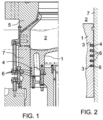
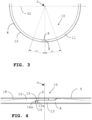
- a piston 1 which has a side provided with several ring grooves 3 of which the top groove 3 receives a piston top ring 4 and the lower piston rings 6 have been inserted in the lower grooves 3.
- the top piston ring 4 and the lower piston rings 6 form a so-called ring pack of cooperating piston rings 4, 6.
- the piston 1 is of a large two-stroke turbo-charged uniflow-scavenged crosshead engine design and the piston 1 defines together with a cylinder liner 7 and a cylinder cover 5 a combustion chamber 2.
- the piston rings 4, 6 prevent the gas pressure in the combustion chamber 2 from penetrating to a space below the piston 1.
- Figs. 3 to 6 illustrate an example embodiment of a piston ring 4 according to the invention.
- the piston ring 4, 6 have a ring body 11, a diameter 32, a height 21, an upper ring surface 22, a lower ring surface 23, an outer ring surface 12 and an inner ring surface 24.
- the piston ring 4 has a ring partition 10 comprising first- and second engaging end portions 8, 9, which substantially prevents combustion gases from the combustion chamber 2 to flow through the ring partition 10.
- the ring partition 10 renders it possible partly to expand the ring diameter at the mounting in the ring groove 3, partly to permit two engaging end the portions 8, 9 of the piston ring 4 to withdraw from each other as the piston ring 4 gets worn during use.
- the first engaging end portion 8 comprises a circumferentially extending finger 13 and the second engaging end portion 9 comprises a circumferentially extending recess 14.
- the finger 13 is received and may slide in the recess 14.
- a gap area 15 Between the end 13a of the finger 13 and the end 14a of the recess 14 is a gap area 15, in which gap area only the end portion 9 with the recess 14 constitutes part of the outer ring surface 12, which during operation of the engine slides against the cylinder liner 7 and seal against the pressure in a combustion chamber 2 above the piston 1.
- the outer ring surface 12 of the piston ring 4, 6 at least in the ring partition 10 is, as seen in cross-section, convex and part of an imaginary circle having a center 20 and a radius of curvature 25 of a least 0,8 times, preferably at least 1 times the diameter of the piston ring 4, 6.
- at least a sufficient part of the outer ring surface 12 also in the gap area 15 provides an effective sealing against the pressure in a combustion chamber 2 above the piston 1, so that problems related to coating damages and blow by of combustions gases from the combustion chamber 2 above the piston 1 are avoided.
- Line 18 in Fig. 4 indicates the border between a lower part of the outer ring surface 12 sliding against the cylinder liner 7 and providing proper sealing effect and the remaining outer ring surface 12 above line 18, which does not provide effective sealing.
- the outer ring surface 12 of the piston ring 4, 6 with a diameter of 800 mm and prepared according to the invention is convex with a radius of curvature 25 of a least 800 mm in at least that part of the ring partition 10 comprising the gap area 15.
- the outer ring surface 12 of the piston ring 4, 6 will be experienced as being approximately flat in this ring partition 10, hence providing optimum sealing effect.
- the circumferential extent of the ring partition 10 extends 20 angular degrees in each circumferential direction from the gap area 15.
- Fig. 5 is seen a cross-section view of an embodiment of a piston ring 4, 6 having a radius of 800 mm and seen in the ring partition 10, where the radius of curvature 25 is 900 mm, so the outer ring surface 12 seems approximately flat over most of its height.
- the height of the piston ring is 18 mm and the center of the outer ring surface curvature is in middle, i.e. 9 mm from below.
- the outer ring surface 12 is part of an imaginary circle, the center 20 of which, as seen in a horizontal plan, containing the lower ring surface 23.
- the center 20 of the imaginary circle, as seen in a horizontal plane containing the lower ring surface 23, is situated at a distance D that is between 1/4 and 3/4, preferably at least about 2/3 of the height of the piston ring 4, 6 from the lower surface 23 of the piston ring 4, 6.
- the outer ring surface 12 of the piston ring 4, 6 at least in said ring partition 10 is essential flat over at least 3/4 of its height.
- the ring partition 10 of the piston ring 4, 6 with first- and second engaging end portions 8, 9 is designed in such a way that the recess 14 opens to said outer ring surface 12 and to said lower ring surface 23, and the finger 13 being flush with said outer ring surface 12 and with said lower ring surface 23.
- the ring body 11 may advantageously be designed non-circular so that the pressure between the cylinder liner 7 and the outer ring surface 12 of the piston ring 4, 6 in the area of the ring partition 10 is lower than on the remaining circumference of the top piston ring.
- piston ring 4, 6 may be coated with a thermal spray coating or with a galvanic coating.
- piston ring 4, 6 may be provided with controlled leakage grooves in the outer ring surface 12 for allowing a controlled flow of gas from above to below said piston ring 4, 6.
- the piston ring 4, 6 may be a top and/or second piston ring.
Landscapes
- Engineering & Computer Science (AREA)
- General Engineering & Computer Science (AREA)
- Mechanical Engineering (AREA)
- Pistons, Piston Rings, And Cylinders (AREA)
- Chemical & Material Sciences (AREA)
- Combustion & Propulsion (AREA)
Applications Claiming Priority (1)
| Application Number | Priority Date | Filing Date | Title |
|---|---|---|---|
| DKPA202101044A DK181183B1 (en) | 2022-03-02 | 2022-03-02 | Piston ring for a large two-stroke turbo-charged uniflow-scavenged crosshead internal combustion engine |
Publications (3)
| Publication Number | Publication Date |
|---|---|
| EP4239227A1 true EP4239227A1 (fr) | 2023-09-06 |
| EP4239227B1 EP4239227B1 (fr) | 2025-12-03 |
| EP4239227C0 EP4239227C0 (fr) | 2025-12-03 |
Family
ID=85321195
Family Applications (1)
| Application Number | Title | Priority Date | Filing Date |
|---|---|---|---|
| EP23157754.5A Active EP4239227B1 (fr) | 2022-03-02 | 2023-02-21 | Segment de piston pour un grand moteur à combustion interne à crosse à balayage à deux temps et à turbocompresseur |
Country Status (5)
| Country | Link |
|---|---|
| EP (1) | EP4239227B1 (fr) |
| JP (2) | JP7467699B2 (fr) |
| KR (1) | KR102563112B1 (fr) |
| CN (1) | CN116696586B (fr) |
| DK (1) | DK181183B1 (fr) |
Families Citing this family (1)
| Publication number | Priority date | Publication date | Assignee | Title |
|---|---|---|---|---|
| EP4682408A1 (fr) * | 2024-07-18 | 2026-01-21 | WinGD Ltd. | Segment de piston |
Citations (5)
| Publication number | Priority date | Publication date | Assignee | Title |
|---|---|---|---|---|
| EP2045488B1 (fr) * | 2007-10-05 | 2010-09-29 | Mitsubishi Heavy Industries, Ltd. | Segment de piston de moteur réciproque |
| JP2015183822A (ja) * | 2014-03-26 | 2015-10-22 | 三菱重工業株式会社 | ピストンリング及び該ピストンリングを備えるエンジン |
| WO2015165634A1 (fr) | 2014-04-30 | 2015-11-05 | Federal-Mogul Burscheid Gmbh | Segment de piston avec surfaces de contact bombées dans la zone de jonction |
| EP3168505A1 (fr) * | 2015-11-12 | 2017-05-17 | MAN Diesel & Turbo, filal af MAN Diesel & Turbo SE, Tyskland | Segment de piston supérieur pour un grand moteur turbocompressé deux temps à combustion interne à allumage par compression avec crosses |
| EP3933232A1 (fr) | 2020-06-15 | 2022-01-05 | MAN Energy Solutions, filial af MAN Energy Solutions SE, Tyskland | Segment de piston avec revêtement dur |
Family Cites Families (8)
| Publication number | Priority date | Publication date | Assignee | Title |
|---|---|---|---|---|
| DK171422B1 (da) * | 1992-11-23 | 1996-10-21 | Man B & W Diesel Gmbh | Stempeltopring til en forbrændingsmotor |
| JP2003254157A (ja) * | 2002-03-05 | 2003-09-10 | Nippon Piston Ring Co Ltd | ピストンリング |
| EP2423539B1 (fr) * | 2010-08-31 | 2014-04-02 | Burckhardt Compression AG | Agencement d'étanchéification |
| JP5755156B2 (ja) | 2012-01-25 | 2015-07-29 | 三菱重工業株式会社 | ピストンリングおよび、そのピストンリングを備えたエンジン |
| US8807571B2 (en) * | 2012-09-28 | 2014-08-19 | Air Products And Chemicals, Inc. | Wear-compensating sealing ring assembly |
| JP6062382B2 (ja) * | 2014-02-25 | 2017-01-18 | 三菱重工業株式会社 | ピストンリング及び該ピストンリングを備えるエンジン |
| DK178468B1 (en) * | 2014-09-19 | 2016-04-11 | Man Diesel & Turbo Deutschland | A top piston ring for a large two-stroke turbo-charged uniflow-scavenged internal combustion engine with crossheads |
| EP3889471B1 (fr) * | 2020-04-02 | 2024-06-12 | Winterthur Gas & Diesel Ltd. | Segment de piston |
-
2022
- 2022-03-02 DK DKPA202101044A patent/DK181183B1/en active IP Right Grant
-
2023
- 2023-01-06 CN CN202310017468.0A patent/CN116696586B/zh active Active
- 2023-01-13 JP JP2023003439A patent/JP7467699B2/ja active Active
- 2023-01-31 KR KR1020230012298A patent/KR102563112B1/ko active Active
- 2023-02-21 EP EP23157754.5A patent/EP4239227B1/fr active Active
- 2023-06-30 JP JP2023107716A patent/JP2023129437A/ja active Pending
Patent Citations (5)
| Publication number | Priority date | Publication date | Assignee | Title |
|---|---|---|---|---|
| EP2045488B1 (fr) * | 2007-10-05 | 2010-09-29 | Mitsubishi Heavy Industries, Ltd. | Segment de piston de moteur réciproque |
| JP2015183822A (ja) * | 2014-03-26 | 2015-10-22 | 三菱重工業株式会社 | ピストンリング及び該ピストンリングを備えるエンジン |
| WO2015165634A1 (fr) | 2014-04-30 | 2015-11-05 | Federal-Mogul Burscheid Gmbh | Segment de piston avec surfaces de contact bombées dans la zone de jonction |
| EP3168505A1 (fr) * | 2015-11-12 | 2017-05-17 | MAN Diesel & Turbo, filal af MAN Diesel & Turbo SE, Tyskland | Segment de piston supérieur pour un grand moteur turbocompressé deux temps à combustion interne à allumage par compression avec crosses |
| EP3933232A1 (fr) | 2020-06-15 | 2022-01-05 | MAN Energy Solutions, filial af MAN Energy Solutions SE, Tyskland | Segment de piston avec revêtement dur |
Also Published As
| Publication number | Publication date |
|---|---|
| DK181183B1 (en) | 2023-04-12 |
| CN116696586B (zh) | 2024-06-07 |
| JP2023129256A (ja) | 2023-09-14 |
| DK202101044A1 (en) | 2023-04-12 |
| CN116696586A (zh) | 2023-09-05 |
| KR102563112B1 (ko) | 2023-08-03 |
| JP7467699B2 (ja) | 2024-04-15 |
| EP4239227B1 (fr) | 2025-12-03 |
| JP2023129437A (ja) | 2023-09-14 |
| EP4239227C0 (fr) | 2025-12-03 |
Similar Documents
| Publication | Publication Date | Title |
|---|---|---|
| EP2998617B1 (fr) | Segment de piston supérieur pour un grand moteur à combustion interne turbocompressé deux temps à récupération de type uniflow | |
| EP4239227B1 (fr) | Segment de piston pour un grand moteur à combustion interne à crosse à balayage à deux temps et à turbocompresseur | |
| RU2528227C1 (ru) | Конструкция для двигателя внутреннего сгорания | |
| KR101889706B1 (ko) | 크로스헤드를 포함하는 대형 2 행정 터보 차징 압축 점화 내연 기관용 상부 피스톤 링 | |
| US9334830B2 (en) | Piston assembly for a reciprocating engine | |
| US4384729A (en) | Interlocking dual plane gapped compression rings | |
| US20140000549A1 (en) | Compression ring for an engine | |
| KR20140123588A (ko) | 내연 엔진용 피스톤 링 | |
| KR102882667B1 (ko) | 크로스헤드를 갖는 대형 2행정 터보차징 단류-소기식 내연기관 피스톤의 링 팩에 사용하기 위한 피스톤 링 | |
| US20150285181A1 (en) | Cylinder liner with slots | |
| JP6387237B2 (ja) | ピストンリング及び該ピストンリングを備えるエンジン | |
| EP2815116B1 (fr) | Bague de piston pour un moteur à combustion interne | |
| CN112901362A (zh) | 具有衬套捕捉部的发动机气缸衬套以及系统 | |
| US12460598B1 (en) | Seal for cylinder liner assembly and method for making the same |
Legal Events
| Date | Code | Title | Description |
|---|---|---|---|
| PUAI | Public reference made under article 153(3) epc to a published international application that has entered the european phase |
Free format text: ORIGINAL CODE: 0009012 |
|
| STAA | Information on the status of an ep patent application or granted ep patent |
Free format text: STATUS: THE APPLICATION HAS BEEN PUBLISHED |
|
| AK | Designated contracting states |
Kind code of ref document: A1 Designated state(s): AL AT BE BG CH CY CZ DE DK EE ES FI FR GB GR HR HU IE IS IT LI LT LU LV MC ME MK MT NL NO PL PT RO RS SE SI SK SM TR |
|
| STAA | Information on the status of an ep patent application or granted ep patent |
Free format text: STATUS: REQUEST FOR EXAMINATION WAS MADE |
|
| 17P | Request for examination filed |
Effective date: 20231117 |
|
| RBV | Designated contracting states (corrected) |
Designated state(s): AL AT BE BG CH CY CZ DE DK EE ES FI FR GB GR HR HU IE IS IT LI LT LU LV MC ME MK MT NL NO PL PT RO RS SE SI SK SM TR |
|
| STAA | Information on the status of an ep patent application or granted ep patent |
Free format text: STATUS: EXAMINATION IS IN PROGRESS |
|
| 17Q | First examination report despatched |
Effective date: 20240724 |
|
| GRAP | Despatch of communication of intention to grant a patent |
Free format text: ORIGINAL CODE: EPIDOSNIGR1 |
|
| STAA | Information on the status of an ep patent application or granted ep patent |
Free format text: STATUS: GRANT OF PATENT IS INTENDED |
|
| INTG | Intention to grant announced |
Effective date: 20250729 |
|
| GRAS | Grant fee paid |
Free format text: ORIGINAL CODE: EPIDOSNIGR3 |
|
| GRAA | (expected) grant |
Free format text: ORIGINAL CODE: 0009210 |
|
| STAA | Information on the status of an ep patent application or granted ep patent |
Free format text: STATUS: THE PATENT HAS BEEN GRANTED |
|
| RAP3 | Party data changed (applicant data changed or rights of an application transferred) |
Owner name: EVERLLENCE, FILIAL AF EVERLLENCE SE, TYSKLAND |
|
| AK | Designated contracting states |
Kind code of ref document: B1 Designated state(s): AL AT BE BG CH CY CZ DE DK EE ES FI FR GB GR HR HU IE IS IT LI LT LU LV MC ME MK MT NL NO PL PT RO RS SE SI SK SM TR |
|
| REG | Reference to a national code |
Ref country code: CH Ref legal event code: F10 Free format text: ST27 STATUS EVENT CODE: U-0-0-F10-F00 (AS PROVIDED BY THE NATIONAL OFFICE) Effective date: 20251203 Ref country code: GB Ref legal event code: FG4D |
|
| REG | Reference to a national code |
Ref country code: CH Ref legal event code: R17 Free format text: ST27 STATUS EVENT CODE: U-0-0-R10-R17 (AS PROVIDED BY THE NATIONAL OFFICE) Effective date: 20251217 |
|
| REG | Reference to a national code |
Ref country code: DE Ref legal event code: R096 Ref document number: 602023009126 Country of ref document: DE |
|
| REG | Reference to a national code |
Ref country code: IE Ref legal event code: FG4D |
|
| U01 | Request for unitary effect filed |
Effective date: 20251222 |
|
| U07 | Unitary effect registered |
Designated state(s): AT BE BG DE DK EE FI FR IT LT LU LV MT NL PT RO SE SI Effective date: 20260109 |
|
| REG | Reference to a national code |
Ref country code: CH Ref legal event code: U11 Free format text: ST27 STATUS EVENT CODE: U-0-0-U10-U11 (AS PROVIDED BY THE NATIONAL OFFICE) Effective date: 20260301 |
|
| U20 | Renewal fee for the european patent with unitary effect paid |
Year of fee payment: 4 Effective date: 20260225 |
|
| PG25 | Lapsed in a contracting state [announced via postgrant information from national office to epo] |
Ref country code: ES Free format text: LAPSE BECAUSE OF FAILURE TO SUBMIT A TRANSLATION OF THE DESCRIPTION OR TO PAY THE FEE WITHIN THE PRESCRIBED TIME-LIMIT Effective date: 20251203 |
|
| PG25 | Lapsed in a contracting state [announced via postgrant information from national office to epo] |
Ref country code: NO Free format text: LAPSE BECAUSE OF FAILURE TO SUBMIT A TRANSLATION OF THE DESCRIPTION OR TO PAY THE FEE WITHIN THE PRESCRIBED TIME-LIMIT Effective date: 20260303 |
|
| PG25 | Lapsed in a contracting state [announced via postgrant information from national office to epo] |
Ref country code: HR Free format text: LAPSE BECAUSE OF FAILURE TO SUBMIT A TRANSLATION OF THE DESCRIPTION OR TO PAY THE FEE WITHIN THE PRESCRIBED TIME-LIMIT Effective date: 20251203 |
|
| PG25 | Lapsed in a contracting state [announced via postgrant information from national office to epo] |
Ref country code: RS Free format text: LAPSE BECAUSE OF FAILURE TO SUBMIT A TRANSLATION OF THE DESCRIPTION OR TO PAY THE FEE WITHIN THE PRESCRIBED TIME-LIMIT Effective date: 20260303 |
|
| PGFP | Annual fee paid to national office [announced via postgrant information from national office to epo] |
Ref country code: CH Payment date: 20260301 Year of fee payment: 4 |
|
| PG25 | Lapsed in a contracting state [announced via postgrant information from national office to epo] |
Ref country code: PL Free format text: LAPSE BECAUSE OF FAILURE TO SUBMIT A TRANSLATION OF THE DESCRIPTION OR TO PAY THE FEE WITHIN THE PRESCRIBED TIME-LIMIT Effective date: 20251203 |