EP4239248A1 - Kraftstoffsprühdüse - Google Patents
Kraftstoffsprühdüse Download PDFInfo
- Publication number
- EP4239248A1 EP4239248A1 EP23154374.5A EP23154374A EP4239248A1 EP 4239248 A1 EP4239248 A1 EP 4239248A1 EP 23154374 A EP23154374 A EP 23154374A EP 4239248 A1 EP4239248 A1 EP 4239248A1
- Authority
- EP
- European Patent Office
- Prior art keywords
- fuel
- passages
- flow
- remaining
- gallery
- Prior art date
- Legal status (The legal status is an assumption and is not a legal conclusion. Google has not performed a legal analysis and makes no representation as to the accuracy of the status listed.)
- Granted
Links
Images
Classifications
-
- F—MECHANICAL ENGINEERING; LIGHTING; HEATING; WEAPONS; BLASTING
- F23—COMBUSTION APPARATUS; COMBUSTION PROCESSES
- F23R—GENERATING COMBUSTION PRODUCTS OF HIGH PRESSURE OR HIGH VELOCITY, e.g. GAS-TURBINE COMBUSTION CHAMBERS
- F23R3/00—Continuous combustion chambers using liquid or gaseous fuel
- F23R3/28—Continuous combustion chambers using liquid or gaseous fuel characterised by the fuel supply
- F23R3/283—Attaching or cooling of fuel injecting means including supports for fuel injectors, stems, or lances
-
- F—MECHANICAL ENGINEERING; LIGHTING; HEATING; WEAPONS; BLASTING
- F23—COMBUSTION APPARATUS; COMBUSTION PROCESSES
- F23R—GENERATING COMBUSTION PRODUCTS OF HIGH PRESSURE OR HIGH VELOCITY, e.g. GAS-TURBINE COMBUSTION CHAMBERS
- F23R3/00—Continuous combustion chambers using liquid or gaseous fuel
- F23R3/28—Continuous combustion chambers using liquid or gaseous fuel characterised by the fuel supply
- F23R3/30—Continuous combustion chambers using liquid or gaseous fuel characterised by the fuel supply comprising fuel prevapourising devices
-
- F—MECHANICAL ENGINEERING; LIGHTING; HEATING; WEAPONS; BLASTING
- F23—COMBUSTION APPARATUS; COMBUSTION PROCESSES
- F23D—BURNERS
- F23D11/00—Burners using a direct spraying action of liquid droplets or vaporised liquid into the combustion space
- F23D11/10—Burners using a direct spraying action of liquid droplets or vaporised liquid into the combustion space the spraying being induced by a gaseous medium, e.g. water vapour
- F23D11/101—Burners using a direct spraying action of liquid droplets or vaporised liquid into the combustion space the spraying being induced by a gaseous medium, e.g. water vapour medium and fuel meeting before the burner outlet
-
- F—MECHANICAL ENGINEERING; LIGHTING; HEATING; WEAPONS; BLASTING
- F23—COMBUSTION APPARATUS; COMBUSTION PROCESSES
- F23D—BURNERS
- F23D11/00—Burners using a direct spraying action of liquid droplets or vaporised liquid into the combustion space
- F23D11/36—Details
- F23D11/38—Nozzles; Cleaning devices therefor
- F23D11/383—Nozzles; Cleaning devices therefor with swirl means
-
- F—MECHANICAL ENGINEERING; LIGHTING; HEATING; WEAPONS; BLASTING
- F23—COMBUSTION APPARATUS; COMBUSTION PROCESSES
- F23R—GENERATING COMBUSTION PRODUCTS OF HIGH PRESSURE OR HIGH VELOCITY, e.g. GAS-TURBINE COMBUSTION CHAMBERS
- F23R3/00—Continuous combustion chambers using liquid or gaseous fuel
- F23R3/28—Continuous combustion chambers using liquid or gaseous fuel characterised by the fuel supply
- F23R3/34—Feeding into different combustion zones
- F23R3/343—Pilot flames, i.e. fuel nozzles or injectors using only a very small proportion of the total fuel to insure continuous combustion
-
- F—MECHANICAL ENGINEERING; LIGHTING; HEATING; WEAPONS; BLASTING
- F23—COMBUSTION APPARATUS; COMBUSTION PROCESSES
- F23R—GENERATING COMBUSTION PRODUCTS OF HIGH PRESSURE OR HIGH VELOCITY, e.g. GAS-TURBINE COMBUSTION CHAMBERS
- F23R3/00—Continuous combustion chambers using liquid or gaseous fuel
- F23R3/28—Continuous combustion chambers using liquid or gaseous fuel characterised by the fuel supply
- F23R3/34—Feeding into different combustion zones
- F23R3/346—Feeding into different combustion zones for staged combustion
-
- F—MECHANICAL ENGINEERING; LIGHTING; HEATING; WEAPONS; BLASTING
- F23—COMBUSTION APPARATUS; COMBUSTION PROCESSES
- F23D—BURNERS
- F23D2209/00—Safety arrangements
- F23D2209/30—Purging
-
- F—MECHANICAL ENGINEERING; LIGHTING; HEATING; WEAPONS; BLASTING
- F23—COMBUSTION APPARATUS; COMBUSTION PROCESSES
- F23R—GENERATING COMBUSTION PRODUCTS OF HIGH PRESSURE OR HIGH VELOCITY, e.g. GAS-TURBINE COMBUSTION CHAMBERS
- F23R3/00—Continuous combustion chambers using liquid or gaseous fuel
- F23R3/28—Continuous combustion chambers using liquid or gaseous fuel characterised by the fuel supply
- F23R3/286—Continuous combustion chambers using liquid or gaseous fuel characterised by the fuel supply having fuel-air premixing devices
Definitions
- the present invention relates to a fuel spray nozzle for generating a spray of atomised liquid fuel in a combustor of a gas turbine engine.
- a gas turbine engine typically comprises, in axial flow arrangement, a fan, one or more compressors, a combustion system and one or more turbines.
- the combustion system may comprise a plurality of fuel injectors having fuel spray nozzles which combine fuel and air flows and generate sprays of atomised liquid fuel into a combustion chamber. Correct production of the atomised sprays has a significant impact on combustion efficiency.
- injectors for lean-burn combustion systems typically have a pilot fuel circuit and a mains fuel circuit (see for example EP 3798517 A and EP 2570727 A ).
- the pilot fuel circuit produces a central fuel spray from the injector, while the mains fuel circuit produces a coaxial, radially outward fuel spray.
- the injectors each have one or more swirling air flows. As well as atomising the fuel, the air flows serve to maintain separation of the pilot and mains fuel flows until the point of ignition, and to define the flow fields and resulting flame shape in the combustion chamber.
- the fuel flow in each of the pilot fuel circuit and mains fuel circuit is typically varied throughout the combustion cycle of the combustion system. At certain times during the combustion cycle (i.e. during engine ignition and at low power operation), the mains fuel flow is staged out (i.e. shut off) whilst the pilot fuel flow is maintained.
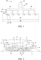
- the fuel spray nozzle has a mains fuel circuit and an annular prefilming surface 156 downstream of it.
- the mains fuel circuit has in flow series a gallery 152 circumferentially wrapped around the nozzle, plural circumferentially spaced passages 160 arranged in a row around the nozzle, and an annular spin chamber 155.
- the gallery can include multiple branches, each branch 159 supplying fuel to a number of the passages 160. Although only two branches are shown in Figure 1 , a typical fuel spray nozzle may have a gallery including, e.g. four branches, each branch supplying fuel flow to three passages.
- Each of the passages 160 can have an upstream portion 153 and a downstream conditioning portion 154.
- the upstream portions 153 of the passages 160 are arranged to evenly distribute the fuel flow between the passages 160 for the entire range of flow conditions of the mains fuel flow.
- the conditioning portions 154 then impart a circumferential component to their respective portions of the mains fuel flow.
- the mains fuel flow enters the fuel circuit at an inlet port 151, and then flows into the gallery 152.
- the upstream portions 153 of the passages 160 receive respective portions of the mains fuel flow from the gallery via inlets 157.
- the portions of the fuel flow are then delivered into the conditioning portions 154 of the respective passages, and from there, into the spin chamber via respective metering orifices 158 of the passages.
- the white circles at the orifices 158 signify their respective sizes which, as shown, are the same for all the passages.
- the fuel flow from all the passages is recombined in the spin chamber 155.
- the mains fuel flow is then discharged from an annular exit port at the downstream end of the spin chamber as a swirling flow onto the annular prefilming surface 156 of the nozzle for atomisation at a trailing edge of the surface into a spray of fine droplets.
- any stagnant fuel retained within the fuel circuit under these circumstances may attain a temperature at which it breaks down into coking products, which in turn may form lacquer on the surface of the injector rendering it susceptible to blockage.
- Such blockages can cause a non-uniform heat traverse to the turbine across the combustor. This can encourage high cycle fatigue and turbine failure. Additionally, the blockages can lead to undesirably high back pressures in the fuel system.
- Aerodynamic nozzle modifications for purging fuel by means of differential static pressures at the prefilmer exit of the nozzle are known in the art (e.g. US 2007/0028619 ).
- Such modified nozzles are configured to introduce a static pressure differential across the mains fuel circuit when the flow of liquid fuel to the circuit is shut off, which creates a propulsive force acting on the remaining fuel in the circuit. This promotes purging the circuit of fuel and thus decreases the risk of coking of fuel residues therein.
- the present invention has been devised in light of the above considerations.
- the present invention provides a fuel spray nozzle for generating a spray of atomised liquid fuel in a combustor of a gas turbine engine, wherein the fuel spray nozzle includes:
- a syphonic purge of the passages is promoted in which a propulsive force on the fuel inside the passages is exerted and a faster and more complete purge of the passages and the gallery can be achieved.
- This improved effectiveness of the purging process can eliminate a need for a separate heat exchanger between a mains fuel circuit and a pilot fuel circuit at the fuel spray nozzle tip. This is advantageous as such heat exchangers can be complex to design, difficult to manufacture and add weight to lean-burn fuel spray nozzles.
- the selected passages of the fuel spray nozzle may extend further axially into the annular spin chamber than the remaining passages to develop the different differential static pressure. This enhances the static pressure differential across the selected passages during periods of low or no fuel supply to exert a propulsive force on the fuel that drains it from the passages and gallery into the spin chamber.
- this configuration also enables the metering orifices of the selected passages to occupy locations within the spin chamber which are more exposed to compressor discharge air, whereas the metering orifices of the remaining passages occupy locations which remain fuel-wetted at the outset of purge.
- the surface tension of the fuel at the metering orifices of the selected passages can be reduced relative to that at the metering orifices of the remaining passages.
- an internal geometry of the selected passages may be different from a corresponding internal geometry of the remaining passages to reduce a threshold differential static pressure of the selected passages relative to a corresponding threshold differential static pressure of the remaining passages, whereby a given differential static pressure developed across stagnant liquid fuel remaining between the inlets and the metering orifices of the selected and remaining passages causes a flow of purging air to enter the gallery from the combustor through the selected passages and exit through the remaining passages, thereby purging the gallery and the passages of fuel.
- the present invention provides a fuel spray nozzle for generating a spray of atomised liquid fuel in a combustor of a gas turbine engine, wherein the fuel spray nozzle includes:
- a flow cross-sectional area of the metering orifices of the selected passages may be larger than a flow cross-sectional area of the metering orifices of the remaining passages to reduce the threshold differential static pressure of the selected passages.
- This configuration can also enhance the static pressure across the selected passages during periods of low or no fuel supply, which in turn can exert a propulsive force on the fuel to drain it from the passages and gallery and into the spin chamber.
- the internal geometry of the selected passages may be different from the corresponding internal geometry of the remaining passages to vary a stagnant liquid fuel meniscus contact angle in the selected passages relative to a corresponding stagnant liquid fuel meniscus contact angle of the remaining passages to reduce the threshold differential static pressure of the selected passages.
- edges of the inlets to the selected passages may be more chamfered than edges of the inlets to the remaining passages and/or edges of outlets from the selected passages to the spin chamber may be more chamfered than edges of outlets from the remaining passages to the spin chamber to vary the stagnant liquid fuel meniscus contact angle. In this way, meniscus adhesion to the surface of the selected passages can be reduced at such locations, decreasing the resistance for the meniscus to move through the selected passages.
- the fuel spray nozzle of the first or second aspect may be further configured such that: the passages are divided into plural mutually exclusive subgroups such that each subgroup contains plural of the passages and each subgroup receives its fuel from a respective branch of the gallery; the gallery is configured such that, when the flow of liquid fuel to the inlet port is shut off, the stagnant fuel remaining in each branch of the gallery is substantially isolated from the stagnant fuel remaining in the other branches of the gallery; and each subgroup contains one of the selected passages and one or more of the remaining passages.
- This configuration ensures that there is at least one selected passage per branch and therefore when the flow of liquid fuel to the inlet port is shut off, the air flow necessarily passes through each branch to purge the fuel therein.
- each subgroup and its respective branch can be purged of fuel independently of the others.
- each subgroup may contain just one of the selected passages and just one or just two of the remaining passages.
- a ratio of one selected passage to one or two of the remaining passages helps to ensure more complete purging.
- the present invention provides a fuel spray nozzle for generating a spray of atomised liquid fuel in a combustor of a gas turbine engine, wherein the fuel spray nozzle includes:
- any small difference in differential static pressures across stagnant liquid fuel remaining between the inlet and the metering orifice of the two passages when the flow of liquid fuel to the inlet port is shut off can produce a lower resistance air path and drive syphonic purging from one passage to the other via the respective branch connecting the two passages.
- there are no other passages fed by the branch there is little danger of unpurged fuel being left behind in those passages.
- the fuel spray nozzle of any aspect may be a lean burn nozzle in which the fuel circuit is a mains fuel circuit, and the nozzle further includes a pilot fuel circuit, the mains fuel circuit being stageable to effect pilot-only and pilot-and-mains staging control.
- the nozzle may be a rich burn nozzle, i.e. without separate pilot and mains fuel circuits for pilot-and-mains staging control.
- the present invention provides a gas turbine engine including in flow series:
- the gas turbine engine of the fourth aspect may further include:
- the gas turbine engine may comprise a gearbox that receives an input from the core shaft and outputs drive to the fan so as to drive the fan at a lower rotational speed than the core shaft.
- the input to the gearbox may be directly from the core shaft, or indirectly from the core shaft, for example via a spur shaft and/or gear.
- the core shaft may rigidly connect the turbine and the compressor, such that the turbine and compressor rotate at the same speed (with the fan rotating at a lower speed).
- the gas turbine engine as described and/or claimed herein may have any suitable general architecture.
- the gas turbine engine may have any desired number of shafts that connect turbines and compressors, for example one, two or three shafts.
- the turbine connected to the core shaft may be a first turbine
- the compressor connected to the core shaft may be a first compressor
- the core shaft may be a first core shaft.
- the engine core may further comprise a second turbine, a second compressor, and a second core shaft connecting the second turbine to the second compressor.
- the second turbine, second compressor, and second core shaft may be arranged to rotate at a higher rotational speed than the first core shaft.
- the second compressor may be positioned axially downstream of the first compressor.
- the second compressor may be arranged to receive (for example directly receive, for example via a generally annular duct) flow from the first compressor.
- the gearbox may be arranged to be driven by the core shaft that is configured to rotate (for example in use) at the lowest rotational speed (for example the first core shaft in the example above).
- the gearbox may be arranged to be driven only by the core shaft that is configured to rotate (for example in use) at the lowest rotational speed (for example only be the first core shaft, and not the second core shaft, in the example above).
- the gearbox may be arranged to be driven by any one or more shafts, for example the first and/or second shafts in the example above.
- the gearbox may be a reduction gearbox (in that the output to the fan is a lower rotational rate than the input from the core shaft). Any type of gearbox may be used.
- the gearbox may be a "planetary” or “star” gearbox, as described in more detail elsewhere herein.
- the gearbox may have any desired reduction ratio (defined as the rotational speed of the input shaft divided by the rotational speed of the output shaft), for example greater than 2.5, for example in the range of from 3 to 4.2, or 3.2 to 3.8, for example on the order of or at least 3, 3.1, 3.2, 3.3, 3.4, 3.5, 3.6, 3.7, 3.8, 3.9, 4, 4.1 or 4.2.
- the gear ratio may be, for example, between any two of the values in the previous sentence.
- the gearbox may be a "star” gearbox having a ratio in the range of from 3.1 or 3.2 to 3.8. In some arrangements, the gear ratio may be outside these ranges.
- a combustor may be provided axially downstream of the fan and compressor(s).
- the combustor may be directly downstream of (for example at the exit of) the second compressor, where a second compressor is provided.
- the flow at the exit to the combustor may be provided to the inlet of the second turbine, where a second turbine is provided.
- the combustor may be provided upstream of the turbine(s).
- each compressor may comprise any number of stages, for example multiple stages.
- Each stage may comprise a row of rotor blades and a row of stator vanes, which may be variable stator vanes (in that their angle of incidence may be variable).
- the row of rotor blades and the row of stator vanes may be axially offset from each other.
- each turbine may comprise any number of stages, for example multiple stages.
- Each stage may comprise a row of rotor blades and a row of stator vanes.
- the row of rotor blades and the row of stator vanes may be axially offset from each other.
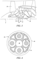
- FIG. 2 illustrates a gas turbine engine 10 having a principal rotational axis 9.
- the engine 10 comprises an air intake 12 and a propulsive fan 23 that generates two airflows: a core airflow A and a bypass airflow B.
- the gas turbine engine 10 comprises a core 11 that receives the core airflow A.
- the engine core 11 comprises, in axial flow series, a low pressure compressor 14, a high-pressure compressor 15, combustion equipment 16, a high-pressure turbine 17, a low pressure turbine 19 and a core exhaust nozzle 20.
- a nacelle 21 surrounds the gas turbine engine 10 and defines a bypass duct 22 and a bypass exhaust nozzle 18.
- the bypass airflow B flows through the bypass duct 22.
- the fan 23 is attached to and driven by the low pressure turbine 19 via a shaft 26 and an epicyclic gearbox 30.
- the core airflow A is accelerated and compressed by the low pressure compressor 14 and directed into the high pressure compressor 15 where further compression takes place.
- the compressed air exhausted from the high pressure compressor 15 is directed into the combustion equipment 16 where it is mixed with fuel and the mixture is combusted.
- the resultant hot combustion products then expand through, and thereby drive, the high pressure and low pressure turbines 17, 19 before being exhausted through the nozzle 20 to provide some propulsive thrust.
- the high pressure turbine 17 drives the high pressure compressor 15 by a suitable interconnecting shaft 27.
- the fan 23 generally provides the majority of the propulsive thrust.
- the epicyclic gearbox 30 is a reduction gearbox.
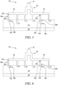
- FIG. 3 An exemplary arrangement for a geared fan gas turbine engine 10 is shown in Figure 3 .
- the low pressure turbine 19 (see Figure 2 ) drives the shaft 26, which is coupled to a sun wheel, or sun gear, 28 of the epicyclic gear arrangement 30.
- a sun wheel, or sun gear, 28 of the epicyclic gear arrangement 30 Radially outwardly of the sun gear 28 and intermeshing therewith is a plurality of planet gears 32 that are coupled together by a planet carrier 34.
- the planet carrier 34 constrains the planet gears 32 to process around the sun gear 28 in synchronicity whilst enabling each planet gear 32 to rotate about its own axis.
- the planet carrier 34 is coupled via linkages 36 to the fan 23 in order to drive its rotation about the engine axis 9.
- an annulus or ring gear 38 Radially outwardly of the planet gears 32 and intermeshing therewith is an annulus or ring gear 38 that is coupled, via linkages 40, to a stationary supporting structure 24.
- low pressure turbine and “low pressure compressor” as used herein may be taken to mean the lowest pressure turbine stages and lowest pressure compressor stages (i.e. not including the fan 23) respectively and/or the turbine and compressor stages that are connected together by the interconnecting shaft 26 with the lowest rotational speed in the engine (i.e. not including the gearbox output shaft that drives the fan 23).
- the "low pressure turbine” and “low pressure compressor” referred to herein may alternatively be known as the "intermediate pressure turbine” and “intermediate pressure compressor”. Where such alternative nomenclature is used, the fan 23 may be referred to as a first, or lowest pressure, compression stage.
- the epicyclic gearbox 30 is shown by way of example in greater detail in Figure 4 .
- Each of the sun gear 28, planet gears 32 and ring gear 38 comprise teeth about their periphery to intermesh with the other gears. However, for clarity only exemplary portions of the teeth are illustrated in Figure 4 .
- Practical applications of a planetary epicyclic gearbox 30 generally comprise at least three planet gears 32.
- the epicyclic gearbox 30 illustrated by way of example in Figures 2 and 3 is of the planetary type, in that the planet carrier 34 is coupled to an output shaft via linkages 36, with the ring gear 38 fixed.
- the epicyclic gearbox 30 may be a star arrangement, in which the planet carrier 34 is held fixed, with the ring (or annulus) gear 38 allowed to rotate. In such an arrangement the fan 23 is driven by the ring gear 38.
- the gearbox 30 may be a differential gearbox in which the ring gear 38 and the planet carrier 34 are both allowed to rotate.
- any suitable arrangement may be used for locating the gearbox 30 in the engine 10 and/or for connecting the gearbox 30 to the engine 10.
- the connections (such as the linkages 36, 40 in the Figure 3 example) between the gearbox 30 and other parts of the engine 10 (such as the input shaft 26, the output shaft and the fixed structure 24) may have any desired degree of stiffness or flexibility.
- any suitable arrangement of the bearings between rotating and stationary parts of the engine may be used, and the disclosure is not limited to the exemplary arrangement of Figure 3 .
- the gearbox 30 has a star arrangement (described above)
- the skilled person would readily understand that the arrangement of output and support linkages and bearing locations would typically be different to that shown by way of example in Figure 3 .
- the present disclosure extends to a gas turbine engine having any arrangement of gearbox styles (for example star or planetary), support structures, input and output shaft arrangement, and bearing locations.
- gearbox styles for example star or planetary
- support structures for example star or planetary
- input and output shaft arrangement for example star or planetary
- bearing locations for example star or planetary
- the gearbox may drive additional and/or alternative components (e.g. the intermediate pressure compressor and/or a booster compressor).
- additional and/or alternative components e.g. the intermediate pressure compressor and/or a booster compressor.
- gas turbine engines to which the present disclosure may be applied may have alternative configurations.
- such engines may have an alternative number of compressors and/or turbines and/or an alternative number of interconnecting shafts.
- the gas turbine engine shown in Figure 2 has a split flow nozzle 18, 20 meaning that the flow through the bypass duct 22 has its own nozzle 18 that is separate to and radially outside the core engine nozzle 20.
- this is not limiting, and any aspect of the present disclosure may also apply to engines in which the flow through the bypass duct 22 and the flow through the core 11 are mixed, or combined, before (or upstream of) a single nozzle, which may be referred to as a mixed flow nozzle.
- One or both nozzles may have a fixed or variable area.
- the described example relates to a turbofan engine, the disclosure may apply, for example, to any type of gas turbine engine, such as an open rotor (in which the fan stage is not surrounded by a nacelle) or turboprop engine, for example.
- the gas turbine engine 10 may not comprise a gearbox 30.
- the geometry of the gas turbine engine 10, and components thereof, is defined by a conventional axis system, comprising an axial direction (which is aligned with the rotational axis 9), a radial direction (in the bottom-to-top direction in Figure 2 ), and a circumferential direction (perpendicular to the page in the Figure 2 view).
- the axial, radial and circumferential directions are mutually perpendicular.
- the combustion equipment 16 of the engine 10 includes a plurality of fuel injectors having lean burn fuel spray nozzles which combine pilot and mains fuel flows, and swirling air flows to generate sprays of atomised liquid fuel into a combustion chamber.
- the mains fuel flow can be staged in and out to provide, as required, pilot-only operation and pilot-and-mains operation.
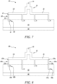
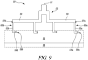
- Figures 5 to 9 are schematic partially cut-away views of selected features of respective variants of a fuel spray nozzle of one of the injectors.
- the variants of Figures 5 to 9 each have a mains fuel circuit and an annular prefilming surface 56 downstream of it.
- the fuel circuit has in flow series: a gallery 52 circumferentially wrapped around the nozzle, plural circumferentially spaced passages 60a, 60b ( Figures 5, 6 , 8 and 9 ) or plural circumferentially spaced passages 60 ( Figure 7 ) arranged in a row around the nozzle, and an annular spin chamber 55.
- the gallery 52 includes multiple branches, each branch 59 supplying fuel to a number of the passages 60a, 60b; 60.
- the passages are divided into plural mutually exclusive subgroups such that each subgroup contains plural of the passages and each subgroup receives its fuel from a respective branch of the gallery 52.
- each subgroup and its respective branch are purged of fuel independently of the others.
- the gallery 52 typically includes more branches 59.
- the spray nozzles of Figures 5 and 6 in which each branch supplies three passages 60a, 60b, may have four such branches
- the spray nozzles of Figures 7 to 9 in which each branch supplies two passages 60a, 60b; 60, may have six such branches.
- the number of passages receiving fuel from the same branch of the gallery is not thus limited, and neither is the number of branches of the same gallery.
- each of the passages 60a, 60b; 60 has an upstream portion 53a, 53b; 53 and a downstream conditioning portion 54a, 54b; 54.
- the upstream portions of the passages extend axially and end at respective metering orifices 58a, 58b; 58, and are configured to evenly distribute the fuel flow between the passages for the entire range of flow conditions of the mains fuel flow.
- the conditioning portions then extend circumferentially from the ends of the upstream portions to impart a circumferential component to their respective portions of the mains fuel flow.
- the fuel flow enters the fuel circuit at an inlet port 51, and then flows into the gallery 52.
- the upstream portions 53a, 53b; 53 of the passages 60a, 60b; 60 receive respective portions of the fuel flow from the gallery via inlets 57a, 57b; 57.
- the portions of the fuel flow are then delivered into the conditioning portions 54a, 54b; 54 of the respective passages, and from there, into the spin chamber.
- the white circles signify the respective sizes of the respective metering orifices 58a, 58b; 58 of the passages.
- the fuel flow from all the passages is recombined in the spin chamber 55.
- the fuel flow is then discharged from an annular exit port at the downstream end of the spin chamber as a swirling flow onto the annular prefilming surface 56 of the nozzle for atomisation at a trailing edge of the surface into a spray of fine droplets.
- a respective differential static pressure develops across stagnant liquid fuel remaining between the inlet 57a, 57b; 57 and the metering orifice 58a, 58b; 58 of each passage 60a, 60b; 60.
- one or more selected passages 60a are configured to develop a different differential static pressure to the remaining passages 60b.
- the different differential static pressure causes a flow of purging air to enter the gallery from the combustor through the selected passages 60a and exit through the remaining passages 60b, thereby purging the gallery and the passages of fuel.
- this configuration of the selected passages 60a generates paths of least resistance within the fuel circuit such that when the flow of liquid fuel to the circuit is shut off, the purging air flow necessarily passes through all the passages 60a, 60b via the gallery 52. Consequently, the gallery and all passages are completely purged of fuel, which reduces the risk of fuel coking therein. This can improve the reliability and longevity of the fuel spray nozzle 50, and of the engine 10 (e.g. its turbines 17, 19) more generally.
- a syphonic purge of the passages 60a, 60b is promoted in which a propulsive force on the fuel inside the passages is exerted and a faster and more complete purge of the passages and the gallery 52 is achieved.
- each branch 59 of the gallery 52 supplies fuel to three passages, one of which is a selected passage 60a and the other two are remaining passages 60b.
- the selected passage 60a extends further axially into the spin chamber 55 than the two remaining passages 60b to develop the different differential static pressure as a result of a spin chamber medium internal flow field. This enhances the static pressure differential across the selected passage 60a during periods of low or no fuel supply to exert a propulsive force on any stagnant liquid fuel, the propulsive force draining the fuel from the passages and gallery 52 into the spin chamber 55.
- the metering orifice 58a of the selected passage 60a occupies a location within the spin chamber which is more exposed to compressor discharge air, whereas the metering orifices 58b of the two remaining passages 60b occupy locations which are fuel-wetted at the outset of purge. In this way, the surface tension of the fuel at the metering orifice of the selected passage is reduced relative to that at the metering orifices of the remaining passages. This effectively reduces the threshold differential pressure across the selected passage needed to overcome surface tension and friction.
- each branch 59 of the gallery 52 supplies fuel to three passages, one of which is a selected passage 60a and the other two are remaining passages 60b.
- a flow cross-sectional area of the metering orifice 58a of the selected passage 60a is greater than the corresponding flow cross-sectional area of the metering orifices 58b of the remaining passages 60b in the branch 59.
- the selected passage has a different internal geometry such that the internal diameter of the metering orifice 58a of the selected passage 60a is larger compared to the diameters of the metering orifices 58b of the remaining passages 60b in the branch. This is illustrated by the differently sized white circles representing the metering orifices 58a, 58b in Figure 6 .
- Another option for changing the internal geometry of the selected passages 60a from a corresponding internal geometry of the remaining passages 60b to lower the threshold differential static pressure for the selected passages is to change a geometry that affects a stagnant liquid fuel meniscus contact angle in the passages when the flow of liquid fuel to the inlet port 51 is shut off.
- This can be achieved, for example, by forming the edges of the inlets 57a to the selected passages 60a to be more chamfered than the edges of the inlets 57b to the remaining passages 60b and/or by forming the edges of outlets from the selected passages 60a to the spin chamber 55 to be more chamfered than the edges of the corresponding outlets from the remaining passages 60b.
- Such chamfered edges vary the contact angle that a fuel meniscus forms with the inlet/outlet of the selected passage 60a.
- a fuel spray nozzle can combine the approach of the variant of Figure 5 , in which one or more selected passages are configured to develop a different differential static pressure to the remaining passages, and the approach of the variant of Figure 6 , in which the selected passages have an internal geometry which reduces their threshold differential static pressure.
- Figure 7 shows a further variant where each branch 59 of the gallery 52 supplies fuel to just two passages 60.
- the passages 60 in the variant of Figure 7 are nominally identical in terms of their lengths and flow cross-sectional areas, i.e. metering orifice diameters.
- any small difference in differential static pressures across stagnant liquid fuel remaining between the inlet 57 and the metering orifice 58 of the two passages when the flow of liquid fuel to the inlet port 51 is shut off can produce a lower resistance air path and drive syphonic purging from one passage to the other via the respective branch 59 connecting the two passages.
- there are no other passages fed by the branch there is little danger of unpurged fuel being left behind in those passages.
- each branch 59 of the gallery 52 supplies fuel to just two passages, one of which is a selected passage 60a and the other of which is a remaining passage 60b.
- the selected passage 60a extends further axially into the spin chamber 55 than the remaining passage 60b, as described in detail in relation to Figure 5 , to develop the enhanced static pressure differential across the selected passage needed to overcome surface tension and flow losses (e.g. friction and turbulence).
- a flow cross-sectional area of the metering orifice 58a of the selected passage 60a is different from a corresponding flow cross-sectional area of the metering orifice 58b of the remaining passage 60b, as described in detail in relation to Figure 6 , to reduce the threshold differential static pressure of the selected passage.
Landscapes
- Engineering & Computer Science (AREA)
- Chemical & Material Sciences (AREA)
- Combustion & Propulsion (AREA)
- Mechanical Engineering (AREA)
- General Engineering & Computer Science (AREA)
- Nozzles (AREA)
- Fuel-Injection Apparatus (AREA)
- Nozzles For Spraying Of Liquid Fuel (AREA)
Applications Claiming Priority (1)
| Application Number | Priority Date | Filing Date | Title |
|---|---|---|---|
| GBGB2202803.9A GB202202803D0 (en) | 2022-03-01 | 2022-03-01 | Fuel spray nozzle |
Publications (2)
| Publication Number | Publication Date |
|---|---|
| EP4239248A1 true EP4239248A1 (de) | 2023-09-06 |
| EP4239248B1 EP4239248B1 (de) | 2025-04-02 |
Family
ID=81075523
Family Applications (1)
| Application Number | Title | Priority Date | Filing Date |
|---|---|---|---|
| EP23154374.5A Active EP4239248B1 (de) | 2022-03-01 | 2023-02-01 | Kraftstoffsprühdüse |
Country Status (3)
| Country | Link |
|---|---|
| US (1) | US12292197B2 (de) |
| EP (1) | EP4239248B1 (de) |
| GB (1) | GB202202803D0 (de) |
Families Citing this family (2)
| Publication number | Priority date | Publication date | Assignee | Title |
|---|---|---|---|---|
| FR3107564B1 (fr) * | 2020-02-24 | 2022-12-02 | Safran Helicopter Engines | Ensemble de combustion pour turbomachine |
| US12454916B2 (en) * | 2023-12-14 | 2025-10-28 | Collins Engine Nozzles, Inc. | Multi-component swirl valves |
Citations (7)
| Publication number | Priority date | Publication date | Assignee | Title |
|---|---|---|---|---|
| US20040250547A1 (en) * | 2003-04-24 | 2004-12-16 | Mancini Alfred Albert | Differential pressure induced purging fuel injector with asymmetric cyclone |
| US20070028619A1 (en) | 2005-08-05 | 2007-02-08 | Rolls-Royce Plc | Fuel injector |
| US20100115955A1 (en) * | 2008-11-11 | 2010-05-13 | Delavan Inc. | Thermal management for fuel injectors |
| US20120047903A1 (en) * | 2008-05-06 | 2012-03-01 | Delavan Inc. | Staged pilots in pure airblast injectors for gas turbine engines |
| EP2570727A2 (de) | 2011-09-16 | 2013-03-20 | Delavan Inc. | Systeme und Verfahren zur Druckabfallregelung in Flüssigkeitskreisläufen durch Wirbelstromabschwächung |
| US20130200179A1 (en) * | 2012-02-08 | 2013-08-08 | Delavan Inc | Liquid fuel swirler |
| EP3798517A1 (de) | 2019-09-26 | 2021-03-31 | Rolls-Royce plc | Kraftstoffsprühdüse |
Family Cites Families (6)
| Publication number | Priority date | Publication date | Assignee | Title |
|---|---|---|---|---|
| US6959535B2 (en) * | 2003-01-31 | 2005-11-01 | General Electric Company | Differential pressure induced purging fuel injectors |
| US9310073B2 (en) * | 2011-03-10 | 2016-04-12 | Rolls-Royce Plc | Liquid swirler flow control |
| US9383097B2 (en) | 2011-03-10 | 2016-07-05 | Rolls-Royce Plc | Systems and method for cooling a staged airblast fuel injector |
| US20120227408A1 (en) * | 2011-03-10 | 2012-09-13 | Delavan Inc. | Systems and methods of pressure drop control in fluid circuits through swirling flow mitigation |
| US9551490B2 (en) * | 2014-04-08 | 2017-01-24 | General Electric Company | System for cooling a fuel injector extending into a combustion gas flow field and method for manufacture |
| US9765972B2 (en) * | 2015-01-30 | 2017-09-19 | Delavan Inc. | Fuel injectors for gas turbine engines |
-
2022
- 2022-03-01 GB GBGB2202803.9A patent/GB202202803D0/en not_active Ceased
-
2023
- 2023-02-01 EP EP23154374.5A patent/EP4239248B1/de active Active
- 2023-02-14 US US18/168,912 patent/US12292197B2/en active Active
Patent Citations (7)
| Publication number | Priority date | Publication date | Assignee | Title |
|---|---|---|---|---|
| US20040250547A1 (en) * | 2003-04-24 | 2004-12-16 | Mancini Alfred Albert | Differential pressure induced purging fuel injector with asymmetric cyclone |
| US20070028619A1 (en) | 2005-08-05 | 2007-02-08 | Rolls-Royce Plc | Fuel injector |
| US20120047903A1 (en) * | 2008-05-06 | 2012-03-01 | Delavan Inc. | Staged pilots in pure airblast injectors for gas turbine engines |
| US20100115955A1 (en) * | 2008-11-11 | 2010-05-13 | Delavan Inc. | Thermal management for fuel injectors |
| EP2570727A2 (de) | 2011-09-16 | 2013-03-20 | Delavan Inc. | Systeme und Verfahren zur Druckabfallregelung in Flüssigkeitskreisläufen durch Wirbelstromabschwächung |
| US20130200179A1 (en) * | 2012-02-08 | 2013-08-08 | Delavan Inc | Liquid fuel swirler |
| EP3798517A1 (de) | 2019-09-26 | 2021-03-31 | Rolls-Royce plc | Kraftstoffsprühdüse |
Also Published As
| Publication number | Publication date |
|---|---|
| GB202202803D0 (en) | 2022-04-13 |
| US20230358405A1 (en) | 2023-11-09 |
| EP4239248B1 (de) | 2025-04-02 |
| US12292197B2 (en) | 2025-05-06 |
Similar Documents
| Publication | Publication Date | Title |
|---|---|---|
| US11215121B2 (en) | Fuel spray nozzle | |
| EP3667169B1 (de) | Kraftstoffsprühdüse | |
| EP3808963B1 (de) | Gasturbinentriebwerk | |
| US11549686B2 (en) | Combustor for a gas turbine engine | |
| EP4239248B1 (de) | Kraftstoffsprühdüse | |
| EP4350126B1 (de) | Äussere laufschaufelluftdichtungskühlanordnung | |
| EP3798517B1 (de) | Kraftstoffsprühdüse | |
| EP3757462B1 (de) | Kraftstoffeinspritzer | |
| US20250376951A1 (en) | Engine system for an aircraft | |
| US11230945B2 (en) | Gas turbine engine with intermediate case bearing arrangement | |
| US12123310B2 (en) | Gas turbine engine with idle thrust ratio | |
| US20240209801A1 (en) | Gas turbine operation | |
| CN111720179A (zh) | 轴承支撑结构 | |
| EP3767179B1 (de) | Kraftstoffeinspritzer für einen gasturbinenmotor | |
| US12123356B2 (en) | Gas turbine engine with higher low spool torque-to-thrust ratio | |
| US12392280B2 (en) | Gas turbine engine with high low spool power extraction ratio | |
| US12595762B2 (en) | Gas turbine engine with bleed diffuser baffles | |
| US12590548B1 (en) | Under-ring oil feed for squeeze film bearing damper | |
| CN121794461A (zh) | 齿轮箱组件 |
Legal Events
| Date | Code | Title | Description |
|---|---|---|---|
| PUAI | Public reference made under article 153(3) epc to a published international application that has entered the european phase |
Free format text: ORIGINAL CODE: 0009012 |
|
| STAA | Information on the status of an ep patent application or granted ep patent |
Free format text: STATUS: THE APPLICATION HAS BEEN PUBLISHED |
|
| AK | Designated contracting states |
Kind code of ref document: A1 Designated state(s): AL AT BE BG CH CY CZ DE DK EE ES FI FR GB GR HR HU IE IS IT LI LT LU LV MC ME MK MT NL NO PL PT RO RS SE SI SK SM TR |
|
| STAA | Information on the status of an ep patent application or granted ep patent |
Free format text: STATUS: REQUEST FOR EXAMINATION WAS MADE |
|
| 17P | Request for examination filed |
Effective date: 20240229 |
|
| RBV | Designated contracting states (corrected) |
Designated state(s): AL AT BE BG CH CY CZ DE DK EE ES FI FR GB GR HR HU IE IS IT LI LT LU LV MC ME MK MT NL NO PL PT RO RS SE SI SK SM TR |
|
| STAA | Information on the status of an ep patent application or granted ep patent |
Free format text: STATUS: EXAMINATION IS IN PROGRESS |
|
| 17Q | First examination report despatched |
Effective date: 20240701 |
|
| GRAP | Despatch of communication of intention to grant a patent |
Free format text: ORIGINAL CODE: EPIDOSNIGR1 |
|
| STAA | Information on the status of an ep patent application or granted ep patent |
Free format text: STATUS: GRANT OF PATENT IS INTENDED |
|
| INTG | Intention to grant announced |
Effective date: 20241203 |
|
| GRAJ | Information related to disapproval of communication of intention to grant by the applicant or resumption of examination proceedings by the epo deleted |
Free format text: ORIGINAL CODE: EPIDOSDIGR1 |
|
| STAA | Information on the status of an ep patent application or granted ep patent |
Free format text: STATUS: EXAMINATION IS IN PROGRESS |
|
| GRAP | Despatch of communication of intention to grant a patent |
Free format text: ORIGINAL CODE: EPIDOSNIGR1 |
|
| STAA | Information on the status of an ep patent application or granted ep patent |
Free format text: STATUS: GRANT OF PATENT IS INTENDED |
|
| GRAS | Grant fee paid |
Free format text: ORIGINAL CODE: EPIDOSNIGR3 |
|
| P01 | Opt-out of the competence of the unified patent court (upc) registered |
Free format text: CASE NUMBER: APP_1798/2025 Effective date: 20250110 |
|
| GRAA | (expected) grant |
Free format text: ORIGINAL CODE: 0009210 |
|
| STAA | Information on the status of an ep patent application or granted ep patent |
Free format text: STATUS: THE PATENT HAS BEEN GRANTED |
|
| INTG | Intention to grant announced |
Effective date: 20250131 |
|
| AK | Designated contracting states |
Kind code of ref document: B1 Designated state(s): AL AT BE BG CH CY CZ DE DK EE ES FI FR GB GR HR HU IE IS IT LI LT LU LV MC ME MK MT NL NO PL PT RO RS SE SI SK SM TR |
|
| REG | Reference to a national code |
Ref country code: GB Ref legal event code: FG4D |
|
| REG | Reference to a national code |
Ref country code: CH Ref legal event code: EP |
|
| REG | Reference to a national code |
Ref country code: IE Ref legal event code: FG4D |
|
| REG | Reference to a national code |
Ref country code: DE Ref legal event code: R096 Ref document number: 602023002633 Country of ref document: DE |
|
| REG | Reference to a national code |
Ref country code: NL Ref legal event code: MP Effective date: 20250402 |
|
| PG25 | Lapsed in a contracting state [announced via postgrant information from national office to epo] |
Ref country code: NL Free format text: LAPSE BECAUSE OF FAILURE TO SUBMIT A TRANSLATION OF THE DESCRIPTION OR TO PAY THE FEE WITHIN THE PRESCRIBED TIME-LIMIT Effective date: 20250402 |
|
| REG | Reference to a national code |
Ref country code: AT Ref legal event code: MK05 Ref document number: 1781589 Country of ref document: AT Kind code of ref document: T Effective date: 20250402 |
|
| PG25 | Lapsed in a contracting state [announced via postgrant information from national office to epo] |
Ref country code: FI Free format text: LAPSE BECAUSE OF FAILURE TO SUBMIT A TRANSLATION OF THE DESCRIPTION OR TO PAY THE FEE WITHIN THE PRESCRIBED TIME-LIMIT Effective date: 20250402 Ref country code: PT Free format text: LAPSE BECAUSE OF FAILURE TO SUBMIT A TRANSLATION OF THE DESCRIPTION OR TO PAY THE FEE WITHIN THE PRESCRIBED TIME-LIMIT Effective date: 20250804 Ref country code: ES Free format text: LAPSE BECAUSE OF FAILURE TO SUBMIT A TRANSLATION OF THE DESCRIPTION OR TO PAY THE FEE WITHIN THE PRESCRIBED TIME-LIMIT Effective date: 20250402 |
|
| REG | Reference to a national code |
Ref country code: LT Ref legal event code: MG9D |
|
| PG25 | Lapsed in a contracting state [announced via postgrant information from national office to epo] |
Ref country code: GR Free format text: LAPSE BECAUSE OF FAILURE TO SUBMIT A TRANSLATION OF THE DESCRIPTION OR TO PAY THE FEE WITHIN THE PRESCRIBED TIME-LIMIT Effective date: 20250703 Ref country code: NO Free format text: LAPSE BECAUSE OF FAILURE TO SUBMIT A TRANSLATION OF THE DESCRIPTION OR TO PAY THE FEE WITHIN THE PRESCRIBED TIME-LIMIT Effective date: 20250702 |
|
| PG25 | Lapsed in a contracting state [announced via postgrant information from national office to epo] |
Ref country code: PL Free format text: LAPSE BECAUSE OF FAILURE TO SUBMIT A TRANSLATION OF THE DESCRIPTION OR TO PAY THE FEE WITHIN THE PRESCRIBED TIME-LIMIT Effective date: 20250402 |
|
| PG25 | Lapsed in a contracting state [announced via postgrant information from national office to epo] |
Ref country code: BG Free format text: LAPSE BECAUSE OF FAILURE TO SUBMIT A TRANSLATION OF THE DESCRIPTION OR TO PAY THE FEE WITHIN THE PRESCRIBED TIME-LIMIT Effective date: 20250402 |
|
| PG25 | Lapsed in a contracting state [announced via postgrant information from national office to epo] |
Ref country code: HR Free format text: LAPSE BECAUSE OF FAILURE TO SUBMIT A TRANSLATION OF THE DESCRIPTION OR TO PAY THE FEE WITHIN THE PRESCRIBED TIME-LIMIT Effective date: 20250402 |
|
| PG25 | Lapsed in a contracting state [announced via postgrant information from national office to epo] |
Ref country code: AT Free format text: LAPSE BECAUSE OF FAILURE TO SUBMIT A TRANSLATION OF THE DESCRIPTION OR TO PAY THE FEE WITHIN THE PRESCRIBED TIME-LIMIT Effective date: 20250402 |
|
| PG25 | Lapsed in a contracting state [announced via postgrant information from national office to epo] |
Ref country code: RS Free format text: LAPSE BECAUSE OF FAILURE TO SUBMIT A TRANSLATION OF THE DESCRIPTION OR TO PAY THE FEE WITHIN THE PRESCRIBED TIME-LIMIT Effective date: 20250702 |
|
| PG25 | Lapsed in a contracting state [announced via postgrant information from national office to epo] |
Ref country code: IS Free format text: LAPSE BECAUSE OF FAILURE TO SUBMIT A TRANSLATION OF THE DESCRIPTION OR TO PAY THE FEE WITHIN THE PRESCRIBED TIME-LIMIT Effective date: 20250802 |
|
| PG25 | Lapsed in a contracting state [announced via postgrant information from national office to epo] |
Ref country code: LV Free format text: LAPSE BECAUSE OF FAILURE TO SUBMIT A TRANSLATION OF THE DESCRIPTION OR TO PAY THE FEE WITHIN THE PRESCRIBED TIME-LIMIT Effective date: 20250402 |
|
| REG | Reference to a national code |
Ref country code: DE Ref legal event code: R097 Ref document number: 602023002633 Country of ref document: DE |
|
| PG25 | Lapsed in a contracting state [announced via postgrant information from national office to epo] |
Ref country code: DK Free format text: LAPSE BECAUSE OF FAILURE TO SUBMIT A TRANSLATION OF THE DESCRIPTION OR TO PAY THE FEE WITHIN THE PRESCRIBED TIME-LIMIT Effective date: 20250402 Ref country code: SM Free format text: LAPSE BECAUSE OF FAILURE TO SUBMIT A TRANSLATION OF THE DESCRIPTION OR TO PAY THE FEE WITHIN THE PRESCRIBED TIME-LIMIT Effective date: 20250402 |
|
| PG25 | Lapsed in a contracting state [announced via postgrant information from national office to epo] |
Ref country code: CZ Free format text: LAPSE BECAUSE OF FAILURE TO SUBMIT A TRANSLATION OF THE DESCRIPTION OR TO PAY THE FEE WITHIN THE PRESCRIBED TIME-LIMIT Effective date: 20250402 |
|
| PG25 | Lapsed in a contracting state [announced via postgrant information from national office to epo] |
Ref country code: EE Free format text: LAPSE BECAUSE OF FAILURE TO SUBMIT A TRANSLATION OF THE DESCRIPTION OR TO PAY THE FEE WITHIN THE PRESCRIBED TIME-LIMIT Effective date: 20250402 |
|
| PG25 | Lapsed in a contracting state [announced via postgrant information from national office to epo] |
Ref country code: SK Free format text: LAPSE BECAUSE OF FAILURE TO SUBMIT A TRANSLATION OF THE DESCRIPTION OR TO PAY THE FEE WITHIN THE PRESCRIBED TIME-LIMIT Effective date: 20250402 |
|
| PG25 | Lapsed in a contracting state [announced via postgrant information from national office to epo] |
Ref country code: IT Free format text: LAPSE BECAUSE OF FAILURE TO SUBMIT A TRANSLATION OF THE DESCRIPTION OR TO PAY THE FEE WITHIN THE PRESCRIBED TIME-LIMIT Effective date: 20250402 |
|
| PLBE | No opposition filed within time limit |
Free format text: ORIGINAL CODE: 0009261 |
|
| STAA | Information on the status of an ep patent application or granted ep patent |
Free format text: STATUS: NO OPPOSITION FILED WITHIN TIME LIMIT |
|
| REG | Reference to a national code |
Ref country code: CH Ref legal event code: L10 Free format text: ST27 STATUS EVENT CODE: U-0-0-L10-L00 (AS PROVIDED BY THE NATIONAL OFFICE) Effective date: 20260211 |
|
| 26N | No opposition filed |
Effective date: 20260105 |
|
| PGFP | Annual fee paid to national office [announced via postgrant information from national office to epo] |
Ref country code: DE Payment date: 20260220 Year of fee payment: 4 |
|
| PGFP | Annual fee paid to national office [announced via postgrant information from national office to epo] |
Ref country code: FR Payment date: 20260224 Year of fee payment: 4 |