EP4239253A2 - Selbstkalibrierung einer belüftungsanlage - Google Patents
Selbstkalibrierung einer belüftungsanlage Download PDFInfo
- Publication number
- EP4239253A2 EP4239253A2 EP23183684.2A EP23183684A EP4239253A2 EP 4239253 A2 EP4239253 A2 EP 4239253A2 EP 23183684 A EP23183684 A EP 23183684A EP 4239253 A2 EP4239253 A2 EP 4239253A2
- Authority
- EP
- European Patent Office
- Prior art keywords
- air
- extraction
- duct
- fan
- blowing
- Prior art date
- Legal status (The legal status is an assumption and is not a legal conclusion. Google has not performed a legal analysis and makes no representation as to the accuracy of the status listed.)
- Pending
Links
Images

Classifications
-
- F—MECHANICAL ENGINEERING; LIGHTING; HEATING; WEAPONS; BLASTING
- F24—HEATING; RANGES; VENTILATING
- F24F—AIR-CONDITIONING; AIR-HUMIDIFICATION; VENTILATION; USE OF AIR CURRENTS FOR SCREENING
- F24F11/00—Control or safety arrangements
- F24F11/30—Control or safety arrangements for purposes related to the operation of the system, e.g. for safety or monitoring
- F24F11/49—Control or safety arrangements for purposes related to the operation of the system, e.g. for safety or monitoring ensuring correct operation, e.g. by trial operation or configuration checks
-
- F—MECHANICAL ENGINEERING; LIGHTING; HEATING; WEAPONS; BLASTING
- F24—HEATING; RANGES; VENTILATING
- F24F—AIR-CONDITIONING; AIR-HUMIDIFICATION; VENTILATION; USE OF AIR CURRENTS FOR SCREENING
- F24F11/00—Control or safety arrangements
- F24F11/62—Control or safety arrangements characterised by the type of control or by internal processing, e.g. using fuzzy logic, adaptive control or estimation of values
- F24F11/63—Electronic processing
-
- F—MECHANICAL ENGINEERING; LIGHTING; HEATING; WEAPONS; BLASTING
- F24—HEATING; RANGES; VENTILATING
- F24F—AIR-CONDITIONING; AIR-HUMIDIFICATION; VENTILATION; USE OF AIR CURRENTS FOR SCREENING
- F24F11/00—Control or safety arrangements
- F24F11/70—Control systems characterised by their outputs; Constructional details thereof
- F24F11/72—Control systems characterised by their outputs; Constructional details thereof for controlling the supply of treated air, e.g. its pressure
- F24F11/74—Control systems characterised by their outputs; Constructional details thereof for controlling the supply of treated air, e.g. its pressure for controlling air flow rate or air velocity
-
- F—MECHANICAL ENGINEERING; LIGHTING; HEATING; WEAPONS; BLASTING
- F24—HEATING; RANGES; VENTILATING
- F24F—AIR-CONDITIONING; AIR-HUMIDIFICATION; VENTILATION; USE OF AIR CURRENTS FOR SCREENING
- F24F13/00—Details common to, or for air-conditioning, air-humidification, ventilation or use of air currents for screening
- F24F13/02—Ducting arrangements
- F24F13/0236—Ducting arrangements with ducts including air distributors, e.g. air collecting boxes with at least three openings
-
- F—MECHANICAL ENGINEERING; LIGHTING; HEATING; WEAPONS; BLASTING
- F24—HEATING; RANGES; VENTILATING
- F24F—AIR-CONDITIONING; AIR-HUMIDIFICATION; VENTILATION; USE OF AIR CURRENTS FOR SCREENING
- F24F7/00—Ventilation
- F24F7/04—Ventilation with ducting systems, e.g. by double walls; with natural circulation
- F24F7/06—Ventilation with ducting systems, e.g. by double walls; with natural circulation with forced air circulation, e.g. by fan positioning of a ventilator in or against a conduit
- F24F7/08—Ventilation with ducting systems, e.g. by double walls; with natural circulation with forced air circulation, e.g. by fan positioning of a ventilator in or against a conduit with separate ducts for supplied and exhausted air with provisions for reversal of the input and output systems
-
- F—MECHANICAL ENGINEERING; LIGHTING; HEATING; WEAPONS; BLASTING
- F24—HEATING; RANGES; VENTILATING
- F24F—AIR-CONDITIONING; AIR-HUMIDIFICATION; VENTILATION; USE OF AIR CURRENTS FOR SCREENING
- F24F2140/00—Control inputs relating to system states
- F24F2140/10—Pressure
-
- F—MECHANICAL ENGINEERING; LIGHTING; HEATING; WEAPONS; BLASTING
- F24—HEATING; RANGES; VENTILATING
- F24F—AIR-CONDITIONING; AIR-HUMIDIFICATION; VENTILATION; USE OF AIR CURRENTS FOR SCREENING
- F24F2140/00—Control inputs relating to system states
- F24F2140/40—Damper positions, e.g. open or closed
Definitions
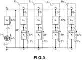
- a non-limiting example of known residential ventilation installation comprises a ventilation system comprising a fan 1 for extracting a flow of air at fixed or variable speed, preferably placed in a volute of a central box 2 comprising a number N of air inlet tappings such that the three air inlet tappings 3 1 , 3 2 , 3 3 visible on the figure 1 , each connected to a first end of an air extraction duct 4 1 , 4 2 , 4 3 , a plurality of air extraction vents such as the three extraction vents 5 1 , 5 2 , 5 3 each connected to the other end of an extraction duct, and at least one rejection device 6 such as a roof cap, connected to an outlet 7 of the central box 2 via a rejection duct 8.
- a ventilation system comprising a fan 1 for extracting a flow of air at fixed or variable speed, preferably placed in a volute of a central box 2 comprising a number N of air inlet tappings such that the three air inlet tappings 3 1 , 3 2 , 3 3 visible
- the extraction ducts equipped with extraction vents lead, for example, into wet rooms (bathroom, toilets, kitchen) and are made up of mechanical parts that can adapt the opening (or passage section) of the air according to one or more parameters such as, but not limited to, the humidity level of the room, detection of the presence of a person, or by any mechanical action (kitchen pull, etc.).
- the air extraction fan 1 and the extraction vents are generally independent of each other.
- the air extraction fan 1 extracts an overall airflow by supplying arrangement of the vents an overall pressure allowing them to operate at the correct extraction rate.
- Each extraction vent constitutes a flow regulator with adjustable passage opening which operates by modifying the passage section of the air entering the corresponding duct according to humidity or customer needs without taking into account the state of the centralized exhaust fan 1. In a so-called jump speed system depending on the flow, the system can detect a variation in the flow and adapt the speed of the fan 1 in order to modify the pressure available for the vents.
- the extraction mouths 5 1 , 5 2 , 5 3 of the figure 1 are replaced by mouths 5 1 ′ , 5 2 ′ And 5 3 ′ whose function is purely aesthetic, and the flow regulators with adjustable passage opening are constituted by registers 5 1 " , 5 2 " And 5 3 " each comprising a movable flap, and placed inside the air inlet tappings of the central box 2.
- Each damper will adjust the position of the flap in order to meet the extraction rate requirement of the room to which it is connected via the extraction duct, depending on information from sensors such as, but not limited to, humidity sensors, VOCs, etc.
- each tapping is additionally equipped with a flow sensor.
- Each damper can thus regulate the position of the associated flap to make the flow measured by the flow sensor correspond to a set flow.
- Flow sensors are expensive devices.
- the pressure drops may have changed, for example due to fouling of the extraction ducts.
- the object of the present invention is to overcome the limitations of the prior art by proposing a simple solution for precisely determining the pressure drops of a ventilation installation, consisting in determining in situ the pressure drops of the installation, whether either at the time of the first commissioning of the installation, or at any time during the use of the installation.
- said open position preferably corresponds to a maximum position for which the flow regulator associated with the i th air extraction or blowing duct allows passage of a maximum flow.
- the method further comprises the determination and memorization in situ of a pressure drop coefficient k R associated with said at least one exhaust or air inlet duct.
- Each flow regulator can be an air extraction or insufflation mouth arranged at a second end of the corresponding air extraction or insufflation duct.
- each flow regulator is a register arranged inside the corresponding air inlet or outlet tapping of said central box.
- the self-calibration means can also be capable of determining a pressure drop coefficient k R associated with said at least one exhaust or air inlet duct.
- each extraction branch (each branch comprising an extraction duct and, at the two ends of the duct, an extraction mouth and a damper extraction), and on the other hand, of the rejection branch or branches (each rejection branch comprising a rejection sheath and a roof cap).
- the air extraction fan 1 can be a fan whose turbine rotates at a fixed speed.
- the fan may be variable speed. In this case, it is possible to control the speed of rotation of the turbine (for example by a control at constant speed or at constant pressure or at constant flow, or at constant torque).
- a self-calibration method aims to allow self-calibration means included in the central box 2 (typically a controller not shown) to determine in situ at least the pressure drop coefficient k i associated with each duct of each branch B i of the installation.
- the coefficients k i thus determined are stored in a memory (not shown) associated with the controller.
- the controller is then able to calculate, at any time during operation of the ventilation installation, the actual pressure drop ⁇ Pg i of a 4i duct of the branch B i for any flow rate Q i , by application of the first equality of the relation (1) or (2).
- the ventilation system is equipped, inside the central box 2, with a pressure sensor (not shown) which measures the value ⁇ P.
- This pressure sensor has a measurement point placed between the roof of the airflow air flow extraction fan 1 and the air inlet tappings 3 1 , ... 3 i , ... 3 N , and another measurement point outside to measure the atmospheric pressure P 0 serving as a reference.
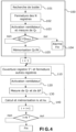
- the method preferably begins with a preliminary phase 100 aimed at defining the reference (setting to zero) of the position of the flaps of the various 5" dampers i and at estimating the internal air leaks of the installation.
- Knowledge by the controller of the position of the registers can indeed be made necessary according to the technology used for these dampers, for example in the non-limiting case where these dampers use a stepper motor without a position sensor to change the position of the damper, that is to say to move a shutter between an open position and a closed position corresponding to mechanical stops.
- the preliminary phase 100 begins with a step 101 during which the controller, preferably positioned inside the central box 2, sends each register 5" i (i varying from 1 to N) a stop search order.
- the controller commands the closing of all the dampers (step 102) so that each damper 5′′ i finds itself in a closed position in which it allows the passage of a minimum leak rate.
- the controller then activates the air extraction fan 1 at at least a given speed and triggers the measurement or the estimation of the air flow rate Q T of the fan (step 103).
- This measurement or estimation can be implemented in various ways.
- a first solution consists in using a flow sensor at the outlet of the fan, the flow sensor being for example an ultrasound sensor or a vane/iris flow meter with pressure drop measurement.
- Another solution consists in using a map of the fan stored beforehand in the memory associated with the controller, this map giving on the one hand the value of the flow rate Q T according to the power absorbed by the fan, its speed of rotation and of its control, and on the other hand, the pressure P ⁇ made available by the air extraction fan 1 according to the flow rate Q T .
- this map giving on the one hand the value of the flow rate Q T according to the power absorbed by the fan, its speed of rotation and of its control, and on the other hand, the pressure P ⁇ made available by the air extraction fan 1 according to the flow rate Q T .
- this measured or estimated flow must be very low and corresponds only to the internal leaks of the casing since all the registers are closed.
- the controller preferably generates a visual and/or audible alarm (step 104) and the self-calibration process ends, until the problem is resolved.
- the preliminary phase 100 ends with a step 105 during which the controller stores in its associated memory the value of the measured or estimated flow rate Q T , divided by the number N of registers, so as to be able to take into account later counts these per-register leak values.
- the self-calibration process can be continued by the steps making it possible to determine at least the pressure drop coefficient k i of each sheath 4 i in each branch B i , and preferably also the pressure drop coefficient k R of the rejection sheath.
- Sub-case 1 the coefficient a is equal to 2 :
- the controller then commands the starting of the fan 1 at a given speed (any), which allows the system to deliver an available pressure P ⁇ (step 120).
- the controller triggers the measurement of ⁇ P (by the pressure sensor) and the measurement of the air flow Q T according to any of the methods described above.
- the memory associated with the controller has the pressure drop coefficient k i for the branch B i tested and the pressure drop coefficient k R .
- Steps 110 to 140 are repeated until the pressure drop coefficients associated with the N branches have been determined.
- Sub-case 2 the coefficient a is not equal to 2 :
- the ventilation system does not have any pressure sensor and is therefore not able to measure the value ⁇ P.
- FIG. 5 represents the possible steps for implementing a self-calibration method in accordance with the present invention and particularly suited to this case, and for which the fan 1 is here a variable-speed fan:
- the method preferably begins with the preliminary phase 100 aimed at defining the reference (zeroing) of the position of the flaps of the various 5" dampers i and at estimating the internal air leaks of the central box 2, described above in reference to the figure 4 .
- the controller must then proceed by selecting pairs of registers, as will be described below:
- the controller then commands the starting of the fan 1 at a given speed (any), which allows the system to deliver an available pressure P ⁇ (step 220).
- the controller triggers the measurement or the estimation of the air flow Q T according to any one of the methods described above. As only the first damper 5" i is in the open position, the air flow Q T measured corresponds to the flow Q i in the first branch B i , except for tapping leaks.
- the controller also triggers the measurement of the value ⁇ P v_i which corresponds to the pressure of the fan 1 when only the first register of the first branch B i is open This measurement is obtained by using the map of the fan, as stored in the memory associated with the controller.
- the controller then commands the closing of the first register 5" i , and the opening, preferably to the maximum, of a second register 5" i+1 of a second branch B i+1 , for example the register 5" 2 and (step 240). Steps similar to steps 220 to 230 are then applied for this second branch B i+1 .
- the controller commands the starting of the fan 1 at a given speed (any), which allows the system to deliver a new available pressure P ⁇ (step 250)
- the controller triggers the measurement of the air flow Q T according to any one of the methods described above.
- the air flow Q T measured corresponds to the flow Q i+1 in the second branch B i+1 , except for tapping leaks.
- the controller also triggers the measurement of the value ⁇ P v_i+1 which corresponds to the pressure of the fan 1 when only the second register of the second branch B i+1 is open.
- the controller then controls the simultaneous opening, preferably maximum, of the registers of the first branch B i and of the second branch B i+1 (step 270), then controls the starting of the fan 1 at a given speed (any), and triggers the measurement of the air flow Q T according to one any of the methods described above (step 290).
- the measured air flow Q T corresponds to the sum of the flow rates Qi and Q i+1 in the first and the second branch, at the near tapping leaks.
- the controller also triggers the measurement of the value ⁇ P v_i_i+1 which corresponds to the pressure of fan 1 when only the first register and the second register of the first branch B i , respectively the second branch B i +1 , are open.
- the controller has a system of three equations with three unknowns consisting of the three pressure drop coefficients k i , k i+1 and k R sought and can therefore calculate and then store these coefficients in step 300.
- Steps 210 to 300 are repeated for another pair of branches, until all the pressure drop coefficients k i have been calculated.
- Steps a) to i) above are repeated for another pair of registers comprising at least one register different from those constituting the pair of the previous iteration, until the coefficient associated with each is obtained. sheath of the installation.
- the self-calibration methods in accordance with the invention have been described in a non-limiting manner in the case of an air extraction ventilation installation.
- the principles of the invention are nevertheless applicable to the case where the ventilation installation is air-blown. It suffices in this case to replace the air extraction fan 1 with an air supply fan.
- the N air extraction ducts 4 1 , 4 2 , 4 3 become air blowing ducts, and the rejection duct 8 becomes an air inlet duct, preferably equipped with a filter of air. In this case, the pressure drop of this filter must be taken into account in the calculation of the coefficient k R .
- the processes have been described within the framework of the installation schematized on the figure 2 for which flow regulators with adjustable passage opening are dampers 5 1 " , 5 2 " , 5 3 " installed in the tappings of the central box 2.
- the flow regulators can be the adjustable mouths 5 1 , 5 2 , 5 3 shown schematically on the installation of the figure 1 .
- a self-calibration procedure at any time, whether it is on the first installation of the central box 2 and the associated outlets, or after this first installation (for example during an operation of maintenance, or following an incident), and thus to know precisely the pressure drop coefficients of the environment in which the ventilation system operates. Thanks to the invention, it is possible in particular to regularly re-evaluate the coefficients k i , and thus estimate the state of fouling of the ducts. In the case of an air blowing installation, a regular reassessment of the coefficient k R also makes it possible to assess the state of clogging of the air inlet duct filter, and to change it if necessary.
Landscapes
- Engineering & Computer Science (AREA)
- Chemical & Material Sciences (AREA)
- Combustion & Propulsion (AREA)
- Mechanical Engineering (AREA)
- General Engineering & Computer Science (AREA)
- Signal Processing (AREA)
- Physics & Mathematics (AREA)
- Ventilation (AREA)
- Fuzzy Systems (AREA)
- Mathematical Physics (AREA)
- Fluid Mechanics (AREA)
- Air Conditioning Control Device (AREA)
Applications Claiming Priority (2)
| Application Number | Priority Date | Filing Date | Title |
|---|---|---|---|
| FR2109199A FR3126753B1 (fr) | 2021-09-03 | 2021-09-03 | Auto calibration d’une installation de ventilation |
| EP22192267.7A EP4145052B1 (de) | 2021-09-03 | 2022-08-26 | Selbstkalibrierung einer lüftungsanlage |
Related Parent Applications (2)
| Application Number | Title | Priority Date | Filing Date |
|---|---|---|---|
| EP22192267.7A Division-Into EP4145052B1 (de) | 2021-09-03 | 2022-08-26 | Selbstkalibrierung einer lüftungsanlage |
| EP22192267.7A Division EP4145052B1 (de) | 2021-09-03 | 2022-08-26 | Selbstkalibrierung einer lüftungsanlage |
Publications (2)
| Publication Number | Publication Date |
|---|---|
| EP4239253A2 true EP4239253A2 (de) | 2023-09-06 |
| EP4239253A3 EP4239253A3 (de) | 2023-10-18 |
Family
ID=77913321
Family Applications (2)
| Application Number | Title | Priority Date | Filing Date |
|---|---|---|---|
| EP23183684.2A Pending EP4239253A3 (de) | 2021-09-03 | 2022-08-26 | Selbstkalibrierung einer belüftungsanlage |
| EP22192267.7A Active EP4145052B1 (de) | 2021-09-03 | 2022-08-26 | Selbstkalibrierung einer lüftungsanlage |
Family Applications After (1)
| Application Number | Title | Priority Date | Filing Date |
|---|---|---|---|
| EP22192267.7A Active EP4145052B1 (de) | 2021-09-03 | 2022-08-26 | Selbstkalibrierung einer lüftungsanlage |
Country Status (3)
| Country | Link |
|---|---|
| EP (2) | EP4239253A3 (de) |
| ES (1) | ES3020734T3 (de) |
| FR (1) | FR3126753B1 (de) |
Families Citing this family (1)
| Publication number | Priority date | Publication date | Assignee | Title |
|---|---|---|---|---|
| FR3162502A1 (fr) * | 2024-05-24 | 2025-11-28 | Atlantic Climatisation Et Traitement D Air Industrie | Kit aéraulique comprenant un raccord et un caisson aérauliques et un agencement de capteurs de pression absolue |
Citations (1)
| Publication number | Priority date | Publication date | Assignee | Title |
|---|---|---|---|---|
| JPH0420737A (ja) * | 1990-05-14 | 1992-01-24 | Mitsubishi Electric Corp | 空気調和装置 |
Family Cites Families (4)
| Publication number | Priority date | Publication date | Assignee | Title |
|---|---|---|---|---|
| US5573181A (en) * | 1995-01-06 | 1996-11-12 | Landis & Gyr Powers, Inc. | Global control of HVAC distribution system |
| BE1019200A5 (nl) * | 2010-02-24 | 2012-04-03 | Renson Ventilation Nv | Werkwijze voor het inregelen van een centraal ventilatiesysteem, inregelsysteem en centraal ventilatiesysteem met een dergelijk inregelsysteem. |
| FR3061762B1 (fr) * | 2017-01-11 | 2019-05-31 | Vti | Procede de regulation de la vitesse de rotation d'un ventilateur d'extraction d'air vicie |
| WO2019040067A1 (en) * | 2017-08-24 | 2019-02-28 | Siemens Industry, Inc. | SYSTEM AND METHOD FOR CONTROLLING FLUID DISTRIBUTION IN A BUILDING |
-
2021
- 2021-09-03 FR FR2109199A patent/FR3126753B1/fr active Active
-
2022
- 2022-08-26 EP EP23183684.2A patent/EP4239253A3/de active Pending
- 2022-08-26 EP EP22192267.7A patent/EP4145052B1/de active Active
- 2022-08-26 ES ES22192267T patent/ES3020734T3/es active Active
Patent Citations (1)
| Publication number | Priority date | Publication date | Assignee | Title |
|---|---|---|---|---|
| JPH0420737A (ja) * | 1990-05-14 | 1992-01-24 | Mitsubishi Electric Corp | 空気調和装置 |
Also Published As
| Publication number | Publication date |
|---|---|
| EP4145052B1 (de) | 2025-01-15 |
| EP4145052A1 (de) | 2023-03-08 |
| EP4239253A3 (de) | 2023-10-18 |
| ES3020734T3 (en) | 2025-05-23 |
| FR3126753A1 (fr) | 2023-03-10 |
| FR3126753B1 (fr) | 2024-08-02 |
Similar Documents
| Publication | Publication Date | Title |
|---|---|---|
| CA2745974C (fr) | Procede et systeme de correction d'un signal de mesure d'une temperature | |
| EP4145052B1 (de) | Selbstkalibrierung einer lüftungsanlage | |
| EP3754341A1 (de) | Bestimmungsverfahren des vertikalen profils der aufwärts gemessenen windgeschwindigkeit einer windkraftanlage, die mit einem laserfernerkennungssensor ausgestattet ist | |
| CA2556307C (fr) | Debitmetre instationnaire | |
| EP3446067A1 (de) | Verfahren zur schätzung des spiels bei einem elektromagnetischen aktuator | |
| EP4269953B1 (de) | Messung des durchflusses durch elektrische impedanzen piezoelektrischer wandler | |
| EP2395288A1 (de) | Ausgleichsventil | |
| EP3287237B1 (de) | Schraubvorrichtung mit optimierter messung des ausgangsdrehmoments, und entsprechendes verfahren zur bestimmung des ausgangsdrehmoments | |
| EP4220023A1 (de) | Regelung des von einem luftabzugs- oder -einblaslüfter abgegebenen drucks in einer belüftungsanlage | |
| EP3785000B1 (de) | Verfahren und system zur verarbeitung eines von einem sensor gelieferten temperaturmesssignals | |
| WO2010067322A1 (fr) | Dispositif et procédé de détection de fuite | |
| CA2745977C (fr) | Procede et systeme d'estimation d'une temperature de veine dans un turboreacteur | |
| FR2661759A1 (fr) | Procede de reglage de debit dans un dispositif de soufflage d'air et dispositif mettant en óoeuvre le procede. | |
| EP3286468B1 (de) | Ventil und steuerungsverfahren | |
| FR3096133A1 (fr) | Extraction d’une composante vibro-acoustique générée par une source mécanique en régime variable | |
| EP4269952A1 (de) | Ultraschall-flüssigkeitszähler mit zwei drucksensoren | |
| EP2702381B1 (de) | Verfahren und vorrichtung zur messung der luftdichtigkeit | |
| EP3995800B1 (de) | Verfahren zur messung der wassertemperatur in einem zähler | |
| EP3980851B1 (de) | Verfahren zur bestimmung eines prädiktiven modells eines druckverhältnisses für ein doppelstromturbinentriebwerk | |
| FR3096031A1 (fr) | Recalage de modèle par segment ou plan dans une turbomachine | |
| FR2941777A1 (fr) | Mesure de debit dans un ventilateur. | |
| EP3358323A1 (de) | Einschätzung des wärmewiderstands eines gebäudes | |
| EP4367492A1 (de) | Verfahren, vorrichtung und system zur überwachung eines turbinenmotors | |
| WO2019219622A1 (fr) | Débitmètre piézoélectrique |
Legal Events
| Date | Code | Title | Description |
|---|---|---|---|
| PUAI | Public reference made under article 153(3) epc to a published international application that has entered the european phase |
Free format text: ORIGINAL CODE: 0009012 |
|
| STAA | Information on the status of an ep patent application or granted ep patent |
Free format text: STATUS: THE APPLICATION HAS BEEN PUBLISHED |
|
| AC | Divisional application: reference to earlier application |
Ref document number: 4145052 Country of ref document: EP Kind code of ref document: P |
|
| AK | Designated contracting states |
Kind code of ref document: A2 Designated state(s): AL AT BE BG CH CY CZ DE DK EE ES FI FR GB GR HR HU IE IS IT LI LT LU LV MC MK MT NL NO PL PT RO RS SE SI SK SM TR |
|
| PUAL | Search report despatched |
Free format text: ORIGINAL CODE: 0009013 |
|
| AK | Designated contracting states |
Kind code of ref document: A3 Designated state(s): AL AT BE BG CH CY CZ DE DK EE ES FI FR GB GR HR HU IE IS IT LI LT LU LV MC MK MT NL NO PL PT RO RS SE SI SK SM TR |
|
| RIC1 | Information provided on ipc code assigned before grant |
Ipc: F24F 11/74 20180101ALI20230912BHEP Ipc: F24F 11/63 20180101ALI20230912BHEP Ipc: F24F 140/40 20180101ALI20230912BHEP Ipc: F24F 140/10 20180101ALI20230912BHEP Ipc: F24F 13/02 20060101ALI20230912BHEP Ipc: F24F 11/49 20180101ALI20230912BHEP Ipc: F24F 7/08 20060101AFI20230912BHEP |
|
| STAA | Information on the status of an ep patent application or granted ep patent |
Free format text: STATUS: REQUEST FOR EXAMINATION WAS MADE |
|
| 17P | Request for examination filed |
Effective date: 20240411 |
|
| RBV | Designated contracting states (corrected) |
Designated state(s): AL AT BE BG CH CY CZ DE DK EE ES FI FR GB GR HR HU IE IS IT LI LT LU LV MC MK MT NL NO PL PT RO RS SE SI SK SM TR |
|
| STAA | Information on the status of an ep patent application or granted ep patent |
Free format text: STATUS: EXAMINATION IS IN PROGRESS |
|
| 17Q | First examination report despatched |
Effective date: 20250220 |