EP4239254A1 - Klimaanlagensystem mit mehrschleifenwärmepumpe zur unterstützung des niedrigtemperaturstarts eines kraftfahrzeugs und kraftfahrzeug - Google Patents
Klimaanlagensystem mit mehrschleifenwärmepumpe zur unterstützung des niedrigtemperaturstarts eines kraftfahrzeugs und kraftfahrzeug Download PDFInfo
- Publication number
- EP4239254A1 EP4239254A1 EP20959098.3A EP20959098A EP4239254A1 EP 4239254 A1 EP4239254 A1 EP 4239254A1 EP 20959098 A EP20959098 A EP 20959098A EP 4239254 A1 EP4239254 A1 EP 4239254A1
- Authority
- EP
- European Patent Office
- Prior art keywords
- another end
- battery
- heat pump
- liquid cooling
- heat exchanger
- Prior art date
- Legal status (The legal status is an assumption and is not a legal conclusion. Google has not performed a legal analysis and makes no representation as to the accuracy of the status listed.)
- Pending
Links
Images






Classifications
-
- B—PERFORMING OPERATIONS; TRANSPORTING
- B60—VEHICLES IN GENERAL
- B60H—ARRANGEMENTS OF HEATING, COOLING, VENTILATING OR OTHER AIR-TREATING DEVICES SPECIALLY ADAPTED FOR PASSENGER OR GOODS SPACES OF VEHICLES
- B60H1/00—Heating, cooling or ventilating devices
- B60H1/00271—HVAC devices specially adapted for particular vehicle parts or components and being connected to the vehicle HVAC unit
- B60H1/00278—HVAC devices specially adapted for particular vehicle parts or components and being connected to the vehicle HVAC unit for the battery
-
- B—PERFORMING OPERATIONS; TRANSPORTING
- B60—VEHICLES IN GENERAL
- B60H—ARRANGEMENTS OF HEATING, COOLING, VENTILATING OR OTHER AIR-TREATING DEVICES SPECIALLY ADAPTED FOR PASSENGER OR GOODS SPACES OF VEHICLES
- B60H1/00—Heating, cooling or ventilating devices
- B60H1/00642—Control systems or circuits; Control members or indication devices for heating, cooling or ventilating devices
- B60H1/00814—Control systems or circuits characterised by their output, for controlling particular components of the heating, cooling or ventilating installation
- B60H1/00878—Control systems or circuits characterised by their output, for controlling particular components of the heating, cooling or ventilating installation the components being temperature regulating devices
- B60H1/00885—Controlling the flow of heating or cooling liquid, e.g. valves or pumps
-
- B—PERFORMING OPERATIONS; TRANSPORTING
- B60—VEHICLES IN GENERAL
- B60H—ARRANGEMENTS OF HEATING, COOLING, VENTILATING OR OTHER AIR-TREATING DEVICES SPECIALLY ADAPTED FOR PASSENGER OR GOODS SPACES OF VEHICLES
- B60H1/00—Heating, cooling or ventilating devices
- B60H1/00642—Control systems or circuits; Control members or indication devices for heating, cooling or ventilating devices
- B60H1/00814—Control systems or circuits characterised by their output, for controlling particular components of the heating, cooling or ventilating installation
- B60H1/00878—Control systems or circuits characterised by their output, for controlling particular components of the heating, cooling or ventilating installation the components being temperature regulating devices
- B60H1/00899—Controlling the flow of liquid in a heat pump system
- B60H1/00921—Controlling the flow of liquid in a heat pump system where the flow direction of the refrigerant does not change and there is an extra subcondenser, e.g. in an air duct
-
- B—PERFORMING OPERATIONS; TRANSPORTING
- B60—VEHICLES IN GENERAL
- B60H—ARRANGEMENTS OF HEATING, COOLING, VENTILATING OR OTHER AIR-TREATING DEVICES SPECIALLY ADAPTED FOR PASSENGER OR GOODS SPACES OF VEHICLES
- B60H1/00—Heating, cooling or ventilating devices
- B60H1/32—Cooling devices
- B60H1/3204—Cooling devices using compression
- B60H1/3228—Cooling devices using compression characterised by refrigerant circuit configurations
- B60H1/32284—Cooling devices using compression characterised by refrigerant circuit configurations comprising two or more secondary circuits, e.g. at evaporator and condenser side
-
- B—PERFORMING OPERATIONS; TRANSPORTING
- B60—VEHICLES IN GENERAL
- B60H—ARRANGEMENTS OF HEATING, COOLING, VENTILATING OR OTHER AIR-TREATING DEVICES SPECIALLY ADAPTED FOR PASSENGER OR GOODS SPACES OF VEHICLES
- B60H1/00—Heating, cooling or ventilating devices
- B60H1/00271—HVAC devices specially adapted for particular vehicle parts or components and being connected to the vehicle HVAC unit
- B60H2001/00307—Component temperature regulation using a liquid flow
Definitions
- the present invention relates to the field of vehicle heat management technology, and in particular, to a multi-circuit heat pump air-conditioning system supporting start of a vehicle at a low temperature and a vehicle.
- a refrigerant state is changed by designing a refrigerant state change device to enable an electric compressor to operate normally at the low temperature, realizing start of a heat pump system at the low temperature.
- system complexity and cost are increased with the addition of the refrigerant state change device, and reliability and maintainability of the system become worse.
- existing heating modes of the air-conditioning system with a heat pump of the vehicle are not diverse enough to flexibly and fully utilize heat sources inside and outside the vehicle, so that an energy utilization rate of entire system is low. Under extreme conditions, for example, at -30 °C, refrigerant, which is liquid, makes a heating effect of the compressor poor at the low temperature. Therefore, it is necessary to improve the prior art to solve the above problems.
- a multi-circuit heat pump air-conditioning system supporting start of a vehicle at a low temperature includes a coolant system, a heat pump system and an electronic control system.
- the coolant system includes a coolant circuit including a DC/DC, a motor, a battery pack, a coolant pipeline, and hydraulic valves and at least one water pump arranged in the coolant pipeline.
- the heat pump system includes a refrigerant circuit including a gas-liquid separator, a compressor, a battery heat exchanger, a liquid cooling condenser, a coolant heater, a refrigerant pipeline, and hydraulic valves arranged in the refrigerant pipeline.
- the coolant heater is configured to heat a coolant when an ambient temperature is lower than a preset temperature and the heat pump system is in a non-working state
- the compressor is configured to work to heat refrigerant in the refrigerant pipeline after the heat pump system is started.
- the electronic control system includes a communication unit, a processor and a switching module.
- the communication unit is configured to receive an ambient temperature outside the vehicle, temperature control requirements of a passenger compartment and the battery pack, and a heat storage state of the battery pack
- the processor is configured to generate a working mode switching instruction according to the ambient temperature outside the vehicle, the temperature control requirements of the passenger compartment and the battery pack, and the heat storage state of the battery pack
- the switching module is configured to switch connection states of the coolant circuit and/or the refrigerant circuit in response to the working mode switching instruction.
- the communication unit is electrically connected with the processor, the processor is electrically connected with the switching module, and the coolant circuit is thermally connected with the refrigerant circuit.
- the heat pump system includes an HVAC assembly and a battery electronic expansion valve.
- the HVAC assembly includes an internal condenser, an air blower, an air door and an air duct, and the electronic control system further includes an air-conditioning controller.
- the HVAC assembly is electrically connected with the air-conditioning controller, and the air-conditioning controller is electrically connected with the processor.
- An end of the liquid cooling condenser is connected with the end of a motor through a hydraulic valve, another end of the liquid cooling condenser is connected with an end of the battery heat exchanger through a hydraulic valve, another end of the battery heat exchanger is connected with an end of the battery pack through a hydraulic valve, and another end of the battery pack is connected with another end of the motor through a hydraulic valve;
- An end of the internal condenser is connected with an end of the battery electronic expansion valve, another end of the battery electronic expansion valve is connected with an end of the battery heat exchanger, another end of the battery heat exchanger is connected with an end of the gas-liquid separator, another end of the gas-liquid separator is connected with an end of the compressor, and another end of the compressor is connected with another end of the internal condenser.
- the HVAC assembly includes an internal radiator.
- the another end of the liquid cooling condenser is connected with an end of the internal radiator, and another end of the internal radiator is connected with an end of a motor.
- an end of the liquid cooling condenser is connected with an end of the coolant heater, another end of the coolant heater is connected with an end of the internal radiator, and another end of the internal radiator is connected with an end of a motor.
- the HVAC assembly includes an internal evaporator and an evaporator electronic expansion valve.
- the end of the internal condenser is connected with an end of the evaporator electronic expansion valve, another end of the evaporator electronic expansion valve is connected with an end of the internal evaporator, and another end of the internal evaporator is connected with the end of the gas-liquid separator.
- the HVAC assembly includes an internal evaporator and an evaporator electronic expansion valve.
- the another end of the liquid cooling condenser is connected with an end of the coolant heater, and another end of the coolant heater is connected with an end of the battery pack.
- the another end of the internal condenser is connected with an end of the evaporator electronic expansion valve, another end of the evaporator electronic expansion valve is connected with an end of the internal evaporator, and another end of the internal evaporator is connected with the end of the gas-liquid separator.
- the another end of the gas-liquid separator is connected with an end of the liquid cooling condenser, another end of the liquid cooling condenser is connected with an end of the battery electronic expansion valve, and another end of the battery electronic expansion valve is connected with the battery heat exchanger.
- the heat pump system includes a radiator.
- the another end of the liquid cooling condenser is connected with an end of the radiator, and another end of the radiator is connected with the end of the battery heat exchanger through a hydraulic valve.
- the end of the liquid cooling condenser is connected with the another end of the gas-liquid separator, the another end of the liquid cooling condenser is connected with the end of the battery electronic expansion valve, and the another end of the battery electronic expansion valve is connected with the battery heat exchanger.
- the heat pump system includes an HVAC assembly, wherein the HVAC assembly includes an internal evaporator and an evaporator electronic expansion valve; the electronic control system further includes an air-conditioning controller.
- the HVAC assembly is electrically connected with the air-conditioning controller, and the air-conditioning controller is electrically connected with the processor.
- An end of the liquid cooling condenser is connected with an end of the motor through a hydraulic valve, another end of the liquid cooling condenser is connected with an end of the battery heat exchanger through a hydraulic valve, another end of the battery heat exchanger is connected with an end of the battery pack through a hydraulic valve, and another end of the battery pack is connected with another end of the motor through a hydraulic valve.
- the another end of the liquid cooling condenser is connected with an end of the evaporator electronic expansion valve, another end of the evaporator electronic expansion valve is connected with an end of the internal evaporator, another end of the internal evaporator is connected with an end of the gas-liquid separator, another end of the gas-liquid separator is connected with an end of the compressor, and another end of the compressor is connected with the end of the liquid cooling condenser.
- the heat pump system includes a radiator.
- the another end of the liquid cooling condenser is connected with an end of the radiator, and another end of the radiator is connected with an end of the battery heat exchanger through a hydraulic valve.
- the another end of the liquid cooling condenser is connected with an end of the battery heat exchanger, and the end of the battery heat exchanger is connected with the end of the gas-liquid separator.
- the heat pump system includes a battery electronic expansion valve.
- An end of the liquid cooling condenser is connected with an end of the motor through a hydraulic valve, another end of the liquid cooling condenser is connected with an end of the battery heat exchanger through a hydraulic valve, another end of the battery heat exchanger is connected with an end of the battery pack through a hydraulic valve, and another end of the battery pack is connected with another end of the motor through a hydraulic valve.
- the another end of the liquid cooling condenser is connected with an end of the coolant heater, and another end of the coolant heater is connected with an end of the battery pack.
- the another end of the liquid cooling condenser is connected with an end of the battery electronic expansion valve, another end of the battery electronic expansion valve is connected with the another end of the battery heat exchanger, the end of the battery heat exchanger is connected with an end of the gas-liquid separator, another end of the gas-liquid separator is connected with an end of the compressor, and another end of the compressor is connected with the end of the liquid cooling condenser.
- the heat pump system includes a radiator, an HVAC assembly and a battery electronic expansion valve, wherein the HVAC assembly includes an internal condenser.
- An end of the battery pack is connected with an end of the motor through a hydraulic valve, and another end of the battery pack is connected with another end of the motor through a hydraulic valve.
- Another end of the battery heat exchanger is connected with an end of the liquid cooling condenser through a hydraulic valve, another end of the liquid cooling condenser is connected with an end of the radiator, and another end of the radiator is connected with an end of the battery heat exchanger through a hydraulic valve.
- an end of the internal condenser is connected with an end of the battery electronic expansion valve, another end of the battery electronic expansion valve is connected with the another end of the battery heat exchanger, the end of the battery heat exchanger is connected with an end of the gas-liquid separator, another end of the gas-liquid separator is connected with an end of the compressor, and another end of the compressor is connected with another end of the internal condenser.
- a vehicle in a second aspect of the present invention, includes a multi-circuit heat pump air-conditioning system supporting start of the vehicle at a low temperature according to the first aspect of the present invention.
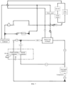
- FIG. 1 is an architecture diagram of a multi-circuit heat pump air-conditioning system supporting start of a vehicle at a low temperature according to an example of the present invention.
- the multi-circuit heat pump air-conditioning system supporting start of a vehicle at a low temperature according to the embodiment of the present invention includes a coolant system, a heat pump system and an electronic control system.
- the coolant system includes a coolant circuit.
- the coolant circuit includes a DC/DC (Direct Current), a motor, a battery pack, a coolant pipeline, and hydraulic valves and at least one water pump arranged in the coolant pipeline.
- the at least one water pump is configured to pump coolant through the coolant circuit along a specific flow direction.
- the motor includes a front motor and a rear motor.
- the front motor is connected in series with the DC/DC.
- the front motor and the DC/DC are connected in parallel with the rear motor.
- the hydraulic valves include, but are not limited to, three-way valves, proportional three-way valves, four-way valves, eight-way valves, and normally-open valves.
- An eight-way valve may be replaced with two four-way valves. According to different connection states of the four-way valves and/or the eight-way valves, series and parallel states may be formed between a battery system and an electric drive system.
- the heat pump system includes a refrigerant circuit.
- the refrigerant circuit includes a gas-liquid separator, a compressor, a battery heat exchanger, a liquid cooling condenser, a coolant heater, a refrigerant pipeline, and hydraulic valves arranged in the refrigerant pipeline.
- the gas-liquid separator is generally installed between an evaporator and the compressor, and main functions of the gas-liquid separator include that: 1 low-temperature steam returning to the compressor is prevented from carrying excessive liquid drops, liquid refrigerant is prevented from entering a compressor cylinder, and the compressor is prevented from being slugged by liquid; 2 too much refrigerant is prevented from diluting compressor oil; 3 the separator also has functions of filtering, oil return, liquid storage, etc.
- the coolant heater is configured to heat a coolant when an ambient temperature is lower than a preset temperature and the heat pump system is in a non-working state.
- the compressor is configured to work to heat the refrigerant in the refrigerant pipeline after the heat pump system is started.
- the refrigerant circuit has a high pressure side and a low pressure side. The compressor works to enable the refrigerant circuit to form the high pressure side and the low pressure side, thereby prompting the refrigerant to flow.
- the electronic control system includes a communication unit, a processor and a switching module.
- the communication unit is configured to receive an ambient temperature outside a vehicle, temperature control requirements of a passenger compartment and the battery pack, and a heat storage state of the battery pack.
- the processor is configured to generate a working mode switching instruction according to the ambient temperature outside the vehicle, the temperature control requirements of the passenger compartment and the battery pack, and the heat storage state of the battery pack.
- the switching module is configured to switch connection states of the coolant circuit and/or the refrigerant circuit in response to the working mode switching instruction.
- the communication unit is electrically connected with the processor.
- the processor is electrically connected with the switching module.
- the coolant circuit is thermally connected with the refrigerant circuit.
- the thermal connection here refers to heat exchange between the coolant circuit and the refrigerant circuit.
- the heat exchange between the coolant and the refrigerant in the two circuits is implemented through the battery heat exchanger or the liquid cooling condenser.
- the heat exchange in the heat exchanger is not a single heat exchange, but a complex heat exchange process involving heat convection and heat conduction.
- an outside temperature sensor is disposed outside a vehicle body, for example, at a hood, a luggage compartment cover or windows, to detect the ambient temperature outside the vehicle and send it to the communication unit.
- the battery heat exchanger may be used as an evaporator.
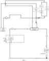
- FIG. 2 is a working principle diagram of a heating mode 1 according to an embodiment of the present invention.
- a multi-circuit heat pump air-conditioning system works in the heating mode 1.
- the multi-circuit heat pump air-conditioning system includes a coolant system, a heat pump system and an electronic control system.
- the coolant system includes an electric drive module, a battery pack, a coolant pipeline, and hydraulic valves and at least one water pump arranged in the coolant pipeline.
- An end of the electric drive module is connected with an end of a liquid cooling condenser through a hydraulic valve.
- Another end of the liquid cooling condenser is connected with an end of an expansion tank.
- Another end of the expansion tank is connected with an end of a battery heat exchanger through a hydraulic valve.
- Another end of the battery heat exchanger is connected with an end of the battery pack through a hydraulic valve.
- Another end of the battery pack is connected with another end of the electric drive module through a hydraulic valve.
- a water pump configured to pump a coolant to flow in a direction from the battery pack to the electric drive module is arranged between the battery pack and the electric drive module.
- a water pump configured to pump a coolant to flow in a direction from the liquid cooling condenser to the battery heat exchanger is arranged between the expansion tank and the battery heat exchanger.
- the direction in which the coolant flows is: electric drive module 4 liquid cooling condenser 4 battery heat exchanger 4 battery pack 4 electric drive module, specifically as shown in FIG. 2 .
- the heat pump system includes a refrigerant circuit, an HVAC (Heating, Ventilation and Air Conditioning) assembly (i.e., HVAC shown in FIG. 2 ) and a battery electronic expansion valve.
- the refrigerant circuit includes a gas-liquid separator, a compressor, a battery heat exchanger, a liquid cooling condenser, a coolant heater, a refrigerant pipeline, and hydraulic valves arranged in the refrigerant pipeline.
- the HVAC assembly includes an internal condenser, an air blower, an air door and an air duct.
- the electronic control system includes an air-conditioning controller.
- the HVAC assembly is electrically connected with the air-conditioning controller.
- the air-conditioning controller is electrically connected with a processor. Opening of the battery electronic expansion valve increases or decreases according to its loads.
- An end of the internal condenser is connected with an end of the battery electronic expansion valve. Another end of the battery electronic expansion valve is connected with another end of the battery heat exchanger. An end of the battery heat exchanger is connected with an end of the gas-liquid separator. Another end of the gas-liquid separator is connected with an end of the compressor. Another end of the compressor is connected with another end of the internal condenser.
- the refrigerant circuit has a high pressure side and a low pressure side. The compressor works to enable the refrigerant circuit to form the high pressure side and the low pressure side, thereby prompting the refrigerant to flow in a specific flow direction in the refrigerant circuit. The direction in which the refrigerant flows is: internal condenser 4 battery heat exchanger 4 gas-liquid separator 4 compressor 4 internal condenser, specifically as shown in FIG. 2 .
- the heat pump system absorbs heat from a battery system through the battery heat exchanger to heat the passenger compartment. At this time, a Coefficient of Performance (COP) is greater than 1.
- COP Coefficient of Performance
- Values of the first preset temperature range may be set according to actual needs.
- the values of the first preset temperature range may be [-10 °C, 10 °C], [-11 °C, 9 °C], [-12 °C, 12 °C] or the like. It should be pointed out that this embodiment is used only to illustrate the values of the first preset temperature range, and should not be considered as a limitation on the protection scope of the present invention. In practical applications, the values of the first preset temperature range include, but are not limited to, the above temperature ranges.
- the multi-circuit heat pump air-conditioning system may not include a radiator as shown in FIG. 2 , or include a radiator as shown in FIG. 1 and the radiator is disposed to be in a short-circuit state.
- an air conditioner may be switched to work in a partial internal circulation state. At this time, fresh air is mixed with circulating air in the passenger compartment.
- the multi-circuit heat pump air-conditioning system may work in the heating mode 1 (for detail, reference may be made to the above description, which will not be repeated here) or in a heating mode 2.
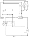
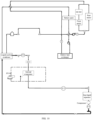
- FIG. 3 is a working principle diagram of a heating mode 2 according to an embodiment of the present invention.
- an HVAC assembly in a multi-circuit heat pump air-conditioning system shown in FIG. 3 further includes an internal radiator. Connection relationships between the internal radiator and other components in the multi-circuit heat pump air-conditioning system are: specifically, another end of a liquid cooling condenser is connected with an end of the internal radiator, and another end of the internal radiator is connected with an end of a motor.
- a heat pump system may be used to heat in combination with the heating mode 1.
- the heat pump system absorbs heat from a battery system through a battery heat exchanger to heat the passenger compartment.
- an electronic control system determines a heat conduction connection mode of the multi-circuit heat pump air-conditioning system to be the heating mode 2.
- the heating mode 2 is a mixed heating mode, with COP>1.
- Coolant flows in the heating mode 2 are: electric drive module 4 liquid cooling condenser 4 battery heat exchanger 4 battery pack 4 electric drive module, and electric drive module 4 liquid cooling condenser 4 internal radiator 4 electric drive module.
- a direction in which the refrigerant flows in the heating mode 2 is: internal condenser 4 battery heat exchanger 4 gas-liquid separator 4 compressor 4 internal condenser.
- the multi-circuit heat air-conditioning system pump may work in the heating mode 3 (for detail, reference may be made to the above description, which will not be repeated here) or in a heating mode 3.
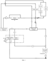
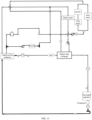
- FIG. 4 is a working principle diagram of a heating mode 3 according to an embodiment of the present invention.
- connection relationships between respective components in a multi-circuit heat pump air-conditioning system shown in FIG. 4 further include the following contents: another end of a liquid cooling condenser is connected with an end of a coolant heater, another end of the coolant heater is connected with an end of an internal radiator, and another end of the internal radiator is connected with another end of an electric drive module.
- the heat pump and the coolant heater are used to heat the passenger compartment at the same time.
- COP the heat pump is heating
- COP 1.
- the heating mode 3 is a mixed heating mode, with COP>1.
- Heat sources of the passenger compartment are from a heat pump system and the coolant heater. Therefore, compared with the heating mode 1, the heating mode 3 may provide more heat for the passenger compartment.
- the heating mode 3 may be used to heat.
- the second preset temperature range includes, but is not limited to, ambient temperature outside a vehicle ⁇ -10 °C.
- Directions in which the coolant flows in the heating mode 3 are: electric drive module 4 liquid cooling condenser 4 battery heat exchanger 4 battery pack 4 electric drive module, and electric drive module 4 liquid cooling condenser 4 coolant heater 4 internal radiator 4 electric drive module.
- a direction in which the refrigerant flows in the heating mode 3 is: internal condenser 4 battery heat exchanger 4 gas-liquid separator 4 compressor 4 internal condenser.
- an air conditioner may be switched to work in an external circulation state.
- This mode may support a defrosting operation to remove frost on an evaporator in the passenger compartment.
- the coolant heater operates at a non-full power.
- the power of the coolant heater in the air-conditioning system is 8 KW.
- operating at a non-full power is only to make up for insufficient heat source part of the heat pump. Not operating at a power of 8 KW may achieve the purpose of energy conservation.
- the coolant heater includes, but is not limited to, a High Voltage Coolant Heater (HVCH), wherein the high voltage heater is also called PTC (Positive Temperature Coefficient) water heater.
- HVCH High Voltage Coolant Heater
- PTC Positive Temperature Coefficient
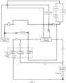
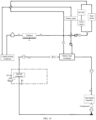
- FIG. 5 is a working principle diagram of a heating mode 4 according to an example of the present invention.
- an HVAC assembly in a multi-circuit heat pump air-conditioning system shown in FIG. 5 further includes an internal evaporator and an evaporator electronic expansion valve.
- Connection relationships between respective components in the multi-circuit heat pump air-conditioning system further include the following contents: an end of an internal condenser is connected with an end of the evaporator electronic expansion valve, another end of the evaporator electronic expansion valve is connected with an end of the internal evaporator, and another end of the internal evaporator is connected with an end of a gas-liquid separator.
- opening of the evaporator electronic expansion valve increases or decreases according to its loads.
- dehumidifying and demisting functions as well as a function of removing frost on the evaporator are operating, the electronic expansion valve is fully opened.
- a heat pump system is used to absorb heat from a battery system while the evaporator in the passenger compartment is used to absorb heat from ambient air in the passenger compartment for heating the passenger compartment.
- This mode is a mixed heating mode, with COP>1.
- a direction in which the coolant flows in the heating mode 4 is: electric drive module 4 liquid cooling condenser 4 battery heat exchanger 4 battery pack 4 electric drive module.
- FIG. 6 is a working principle diagram of a heating mode 5 according to an embodiment of the present invention.
- an HVAC assembly of a multi-circuit heat pump air-conditioning system shown in FIG. 6 further includes an internal evaporator and an evaporator electronic expansion valve.
- Connection relationships between respective components in the multi-circuit heat pump air-conditioning system further include the following contents: an end of an internal condenser is connected with an end of the evaporator electronic expansion valve, another end of the evaporator electronic expansion valve is connected with an end of the internal evaporator, and another end of the internal evaporator is connected with an end of a gas-liquid separator.
- a heat pump system is used to absorb heat from a battery system for helping a coolant heater to heat (operating at a non-full power), and the evaporator in the passenger compartment is used to absorb ambient heat to heat the passenger compartment.
- This mode is a mixed heating mode, with COP>1. Specifically, in this mode, air is mixed in the air-conditioning system, and the internal evaporator in the HVAC assembly is connected in series with the internal condenser in the HVAC assembly.
- Directions in which the coolant flows in the heating mode 5 are: electric drive module 4 liquid cooling condenser 4 battery heat exchanger 4 battery pack 4 electric drive module, and electric drive module 4 liquid cooling condenser 4 coolant heater 4 internal radiator 4 electric drive module.
- FIG. 7 is a working principle diagram of a heating mode 6 according to an embodiment of the present invention.
- an HVAC assembly shown in FIG. 7 further includes an internal evaporator and an evaporator electronic expansion valve.
- another end of a liquid cooling condenser is connected with an end of a coolant heater, another end of the coolant heater is connected with an end of a battery pack, another end of an internal condenser is connected with an end of the evaporator electronic expansion valve, another end of the evaporator electronic expansion valve is connected with an end of the internal evaporator, and another end of the internal evaporator is connected with an end of a gas-liquid separator.
- the coolant heater is first used to heat a coolant.
- a battery heat exchanger is started as an evaporator, and the internal evaporator is closed.
- the coolant heater and the battery heat exchanger are closed.
- COP 1. Air is mixed in the air-conditioning system, and an optimal proportion of internal and external circulation and minimum comfort requirements need to be maintained. If complete internal circulation is selected, it is easy to cause passengers to feel depressed and increase a risk of fogging.
- Directions in which the coolant flows in the heating mode 6 are: electric drive module ⁇ liquid cooling condenser ⁇ battery heat exchanger ⁇ battery pack ⁇ electric drive module, and electric drive module ⁇ liquid cooling condenser ⁇ coolant heater ⁇ battery pack ⁇ electric drive module.
- FIG. 8 is a working principle diagram of a heating mode 7 according to an embodiment of the present invention.
- another end of a gas-liquid separator is connected with an end of a liquid cooling condenser
- another end of the liquid cooling condenser is connected with an end of a battery electronic expansion valve
- another end of the battery electronic expansion valve is connected with a battery heat exchanger.
- the passenger compartment may be quickly heated.
- the battery may be heated through the liquid cooling condenser, mainly to improve the charging efficiency and the discharging current of the battery.
- a three-way valve at the downstream of a compressor controls refrigerant flow distribution, giving priority to ensuring the comfort of the passenger compartment.
- a coolant heater is first used to heat a coolant.
- the battery heat exchanger is started as an evaporator, and an internal evaporator is closed.
- the coolant heater and the battery heat exchanger are closed.
- the passenger compartment is heated. Therefore, starting at a low temperature and using the compressor to work are achieved.
- Directions in which the coolant flows in the heating mode 7 are: electric drive module 4 liquid cooling condenser 4 battery heat exchanger 4 battery pack 4 electric drive module, and electric drive module 4 liquid cooling condenser 4 coolant heater 4 battery pack ⁇ electric drive module.
- a direction in which the refrigerant flows in the heating mode 7 is: liquid cooling condenser / internal condenser 4 battery heat exchanger / internal evaporator 4 gas-liquid separator 4 compressor 4 liquid cooling condenser / internal condenser.
- FIG. 9 is a working principle diagram of a refrigerating mode 1 according to an embodiment of the present invention.
- a heat pump system shown in FIG. 9 further includes a radiator. Another end of a liquid cooling condenser is connected with an end of the radiator, another end of the radiator is connected with an end of a battery heat exchanger through a hydraulic valve, an end of the liquid cooling condenser is connected with another end of a gas-liquid separator, another end of the liquid cooling condenser is connected with an end of a battery electronic expansion valve, and another end of the battery electronic expansion valve is connected with the battery heat exchanger.
- a battery When a battery temperature reaches above 40 °C in summer, a battery has a strong refrigerating requirement, and there is a small heating requirement in a passenger compartment, after the refrigerant flows through a compressor, and its flow distribution is controlled through a three-way valve, so that, in addition to meeting the heating requirement of the passenger compartment, residual heat may be transferred to an environment through a coolant condenser and the radiator for heat dissipation.
- the battery In this mode, the battery is connected in series with a motor through an eight-way valve in a large cycle, and the radiator works.
- a direction in which the coolant flows in the refrigerating mode 1 is: electric drive module ⁇ liquid cooling condenser ⁇ radiator ⁇ battery heat exchanger ⁇ battery pack ⁇ electric drive module.
- a direction in which the refrigerant flows in the refrigerating mode 1 is: liquid cooling condenser / internal condenser ⁇ battery heat exchanger ⁇ gas-liquid separator ⁇ compressor ⁇ liquid cooling condenser / internal condenser.
- FIG. 10 is a working principle diagram of a heating mode 8 and a heating mode 9 according to an embodiment of the present invention.
- a heat pump system further includes an HVAC assembly.
- the HVAC assembly includes an internal evaporator and an evaporator electronic expansion valve.
- An electronic control system further includes an air-conditioning controller.
- the HVAC assembly is electrically connected with the air-conditioning controller.
- the air-conditioning controller is electrically connected with a processor.
- An end of a liquid cooling condenser is connected with an end of a motor through a hydraulic valve. Another end of the liquid cooling condenser is connected with an end of a battery heat exchanger through a hydraulic valve. Another end of the battery heat exchanger is connected with an end of a battery pack through a hydraulic valve. Another end of the battery pack is connected with another end of the motor through a hydraulic valve.
- Another end of the liquid cooling condenser is connected with an end of the evaporator electronic expansion valve. Another end of the evaporator electronic expansion valve is connected with an end of the internal evaporator. Another end of the internal evaporator is connected with an end of a gas-liquid separator. Another end of the gas-liquid separator is connected with an end of a compressor. Another end of the compressor is connected with an end of the liquid cooling condenser.
- the evaporator in the passenger compartment is used to absorb heat in an environment to heat the battery.
- a remote air-conditioning system before or after driving is applied.
- the heating mode 8 is a partial internal circulation state
- the heating mode 9 is a complete internal circulation state.
- a coolant system does not include a radiator or the radiator is short-circuited.
- the third preset temperature range includes, but is not limited to, ambient temperature outside a vehicle>-10 °C.
- a direction in which the coolant flows in the heating modes 8 and 9 is: electric drive module 4 liquid cooling condenser 4 battery heat exchanger 4 battery pack 4 electric drive module.
- a direction in which the refrigerant flows in the heating modes 8 and 9 is: internal condenser ⁇ gas-liquid separator ⁇ compressor ⁇ liquid cooling condenser ⁇ internal condenser.
- FIG. 11 is a working principle diagram of a refrigerating mode 2 according to an embodiment of the present invention.
- FIG. 11 shows a mode in which a passenger compartment has a refrigerating requirement in summer. In this mode, an internal condenser is in an activated state, and dehumidifies fresh air by way of reheating to meet a dehumidification requirement of warming passenger compartment environment.
- a multi-circuit heat pump air-conditioning system shown in FIG. 11 further includes a radiator. Another end of a liquid cooling condenser is connected with an end of the radiator, and another end of the radiator is connected with an end of a battery heat exchanger through a hydraulic valve. The radiator works, and air is mixed in the air-conditioning system.
- a direction in which the coolant flows in the refrigerating mode 2 is: electric drive module ⁇ liquid cooling condenser ⁇ radiator ⁇ battery heat exchanger ⁇ battery pack ⁇ electric drive module.
- a direction in which the refrigerant flows in the refrigerating mode 2 is: internal evaporator ⁇ gas-liquid separator ⁇ compressor ⁇ liquid cooling condenser ⁇ internal evaporator.
- FIG. 12 is a working principle diagram of a refrigerating mode 3 according to an embodiment of the present invention.
- FIG. 12 shows a mode in which a passenger compartment and a battery system are simultaneously refrigerated in summer.
- another end of a liquid cooling condenser is connected with another end of a battery heat exchanger, and an end of the battery heat exchanger is connected with an end of a gas-liquid separator.
- a direction in which the coolant flows in the refrigerating mode 3 is: electric drive module ⁇ liquid cooling condenser ⁇ radiator ⁇ battery heat exchanger ⁇ battery pack ⁇ electric drive module.
- a direction in which the refrigerant flows in the refrigerating mode 3 is: liquid cooling condenser ⁇ internal evaporator / battery heat exchanger ⁇ gas-liquid separator ⁇ compressor ⁇ liquid cooling condenser.
- the coolant system includes a coolant circuit.
- the coolant circuit includes a DC/DC, a motor, a battery pack, a coolant pipeline, and hydraulic valves and at least one water pump arranged in the coolant pipeline.
- the at least one water pump is configured to pump a coolant through the coolant circuit along a specific flow direction.
- the coolant system may not include a radiator or an electrical connection state of the radiator is set to be short-circuited, and the refrigerant transfers heat to a battery through a coolant condenser.
- the heat pump system includes a refrigerant circuit.
- the refrigerant circuit includes a gas-liquid separator, a compressor, a battery heat exchanger, a liquid cooling condenser, a coolant heater, a battery electronic expansion valve, a refrigerant pipeline, and hydraulic valves arranged in the refrigerant pipeline.
- an end of the liquid cooling condenser is connected with an end of the motor through a hydraulic valve, another end of the liquid cooling condenser is connected with an end of the battery heat exchanger through a hydraulic valve, another end of the battery heat exchanger is connected with an end of the battery pack through a hydraulic valve, and another end of the battery pack is connected with another end of the motor through a hydraulic valve;
- another end of the liquid cooling condenser is connected with an end of the coolant heater, and another end of the coolant heater is connected with another end of the battery pack;
- another end of the liquid cooling condenser is connected with an end of the battery electronic expansion valve, another end of the battery electronic expansion valve is connected with another end of the battery heat exchanger, an end of the battery heat exchanger is connected with an end of the gas-liquid separator, another end of the gas-liquid separator is connected with an end of the compressor, and another end of the compressor is connected with another end of the liquid cooling condenser.
- Directions in which the coolant flows in the heating modes 10 and 11 are: electric drive module 4 liquid cooling condenser 4 battery heat exchanger 4 battery pack 4 electric drive module, and electric drive module 4 liquid cooling condenser 4 coolant heater 4 battery pack 4 electric drive module.
- a direction in which the refrigerant flows in the heating modes 9 and 10 is: liquid cooling condenser 4 battery heat exchanger 4 gas-liquid separator 4 compressor 4 liquid cooling condenser.
- the heating mode 9 differs from the heating mode 10 in that: in the heating mode 9, the coolant heater is used to assist in starting the heat pump system and is then closed, while in the heating mode 10, when the battery has a large heat requirement, the coolant heater is no longer closed (operating at a non-full power) and heats the battery together with the heat pump system.
- FIG. 14 is a working principle diagram of a heating mode 12 and a heating mode 13 according to an embodiment of the present invention.
- a coolant system further includes a radiator
- a heat pump system further includes an HVAC assembly and a battery electronic expansion valve.
- the HVAC assembly includes an internal condenser.
- An end of a battery pack is connected with an end of a motor through a hydraulic valve, and another end of the battery pack is connected with another end of the motor through a hydraulic valve.
- Another end of a battery heat exchanger is connected with an end of a liquid cooling condenser through a hydraulic valve, another end of the liquid cooling condenser is connected with an end of the radiator, and another end of the radiator is connected with an end of the battery heat exchanger through a hydraulic valve.
- both a passenger compartment and a battery need to be heated.
- the heat pump system absorbs heat from the coolant in circulation through the battery heat exchanger. A temperature of the coolant continuously decreases. The coolant, when flowing through the radiator, absorbs heat in an environment. At the same time, the passenger compartment is heated without affecting a battery system, and COP>1.
- an electronic control system determines that a heat conduction connection mode of a multi-circuit heat pump air-conditioning system is the heating mode 12.
- the radiator When the ambient temperature outside a vehicle is within a third preset temperature range, the battery has certain heat storage, and the passenger compartment is pre-heated, the radiator is used to collect heat from environment for pre-heating the passenger compartment. It is more effective to heat the passenger compartment at an intermediate ambient temperature outside a vehicle (-10 °C or higher, where a battery temperature is slightly lower than the ambient temperature outside a vehicle).
- the radiator works, and HVAC is in an internal circulation state.
- the electronic control system determines that the heat conduction connection mode of the multi-circuit heat pump air-conditioning system is the heating mode 13.
- series connection between the internal evaporator and condenser may support dehumidification of the passenger compartment in a low temperature environment.
- the multi-circuit heat pump air-conditioning system may have all or part of components shown in FIG. 1 , and for connection relationships between respective components, the connection manners described in one or more embodiments above may be adopted, so that there are a variety of heating and/or refrigerating modes.
- the multi-circuit heat pump air-conditioning system has all components and connection relationships shown in FIG. 1 .
- the electronic control system adopts the heating mode 1 by default, and gradually more mixed modes are carried out in the heating modes 3, 4 and 5.
- the heating mode 6 is adopted. If the battery needs to be heated urgently, the heating modes 7, 10 and 11 are adopted.
- the multi-circuit heat pump air-conditioning system further provides the heating modes 8, 9, 11, etc. applicable to parking air conditioners.
- the heat conduction connection mode of the multi-circuit heat pump air-conditioning system is determined according to the ambient temperature outside a vehicle, the temperature control requirements of the passenger compartment and the battery pack, and the heat storage state of the battery pack.
- the heat pump system may be started at an extremely low temperature and is transitioned to other heating modes, thereby solving problems of battery life and thermal comfort of the passenger compartment in winter, and facilitating flexible use of heat sources inside and outside the vehicle.
- An embodiment of the present invention further provides a vehicle, including a multi-circuit heat pump air-conditioning system supporting start of the vehicle at a low temperature according to any one of the above embodiments.
- the start of the heat pump system at the low temperature is supported and the use of additional components is reduced, without adding additional refrigerant state change device, which may reduce system cost and avoid maintenance of corresponding devices.
- the storage of heat in the passenger compartment to the battery is also supported, and this part of heat is utilized to heat the passenger compartment during next driving (at an interval of about 1-2 hours), so as to improve energy utilization.
Landscapes
- Physics & Mathematics (AREA)
- Thermal Sciences (AREA)
- Engineering & Computer Science (AREA)
- Mechanical Engineering (AREA)
- Air-Conditioning For Vehicles (AREA)
Applications Claiming Priority (1)
| Application Number | Priority Date | Filing Date | Title |
|---|---|---|---|
| PCT/CN2020/124605 WO2022087935A1 (zh) | 2020-10-29 | 2020-10-29 | 一种支持汽车低温启动的多回路热泵空调系统及汽车 |
Publications (2)
| Publication Number | Publication Date |
|---|---|
| EP4239254A1 true EP4239254A1 (de) | 2023-09-06 |
| EP4239254A4 EP4239254A4 (de) | 2024-01-24 |
Family
ID=81383473
Family Applications (1)
| Application Number | Title | Priority Date | Filing Date |
|---|---|---|---|
| EP20959098.3A Pending EP4239254A4 (de) | 2020-10-29 | 2020-10-29 | Klimaanlagensystem mit mehrschleifenwärmepumpe zur unterstützung des niedrigtemperaturstarts eines kraftfahrzeugs und kraftfahrzeug |
Country Status (3)
| Country | Link |
|---|---|
| EP (1) | EP4239254A4 (de) |
| CN (1) | CN116194312B (de) |
| WO (1) | WO2022087935A1 (de) |
Cited By (2)
| Publication number | Priority date | Publication date | Assignee | Title |
|---|---|---|---|---|
| EP4592104A1 (de) * | 2024-01-24 | 2025-07-30 | Volvo Car Corporation | Verfahren zur steuerung eines wärmemanagementsystems eines elektrofahrzeugs, datenverarbeitungsvorrichtung, computerprogramm, computerlesbares speichermedium und verwendungen |
| FR3158782A1 (fr) * | 2024-01-25 | 2025-08-01 | Stellantis Auto Sas | Pompe à chaleur et procédé de gestion d’une telle pompe à chaleur |
Families Citing this family (10)
| Publication number | Priority date | Publication date | Assignee | Title |
|---|---|---|---|---|
| CN115139741A (zh) * | 2022-07-13 | 2022-10-04 | 东风汽车集团股份有限公司 | 一种带热气旁通循环的纯电动车型热泵系统 |
| CN115284820A (zh) * | 2022-07-14 | 2022-11-04 | 东风汽车集团股份有限公司 | 一种冷媒直冷直热式电动车热泵热管理系统 |
| EP4552872A4 (de) * | 2022-08-01 | 2026-03-11 | Shenzhen Yinwang Intelligent Technology Co Ltd | Wärmeverwaltungsanordnung, wärmeverwaltungssystem und fahrzeug |
| CN115402154B (zh) * | 2022-09-30 | 2025-10-14 | 长城汽车股份有限公司 | 一种车辆热管理系统及方法 |
| CN115489262B (zh) * | 2022-10-08 | 2025-09-02 | 江苏大学 | 一种间接式多层级余热回收的热泵空调系统及其控制方法 |
| CN116160820B (zh) * | 2023-03-07 | 2026-04-17 | 浙江极氪智能科技有限公司 | 电动汽车热管理系统、方法及电动汽车 |
| CN116476592B (zh) * | 2023-03-29 | 2026-01-02 | 奇瑞汽车股份有限公司 | 一种新能源汽车热管理系统及汽车 |
| CN116697570A (zh) * | 2023-07-20 | 2023-09-05 | 南京天加环境科技有限公司 | 一种空调系统及其控制方法 |
| CN118269557B (zh) * | 2023-09-22 | 2026-02-10 | 比亚迪股份有限公司 | 热泵空调和汽车 |
| CN120620964A (zh) * | 2025-06-30 | 2025-09-12 | 一汽-大众汽车有限公司 | 一种汽车热管理控制方法 |
Family Cites Families (14)
| Publication number | Priority date | Publication date | Assignee | Title |
|---|---|---|---|---|
| JP2009202735A (ja) * | 2008-02-27 | 2009-09-10 | Denso Corp | 車両用空調装置 |
| JP5297154B2 (ja) * | 2008-11-06 | 2013-09-25 | 三菱重工業株式会社 | 車両空調システムおよびその運転制御方法 |
| KR101566316B1 (ko) * | 2012-12-28 | 2015-11-05 | 한온시스템 주식회사 | 차량용 히트펌프 시스템 |
| FR3025139B1 (fr) * | 2014-08-26 | 2018-03-23 | Psa Automobiles Sa. | Procede de pre-conditionnement de l'habitacle au moyen d'une pompe a chaleur |
| FR3027557A1 (fr) * | 2014-10-24 | 2016-04-29 | Renault Sa | Dispositif de regulation thermique de l'air de l'habitacle et de composants d'un vehicule automobile propulse totalement ou partiellement par un moteur electrique |
| CN204493049U (zh) * | 2015-03-05 | 2015-07-22 | 安徽江淮汽车股份有限公司 | 一种汽车发动机预热系统 |
| CN206765743U (zh) * | 2017-03-07 | 2017-12-19 | 上海蔚来汽车有限公司 | 热泵系统、用于车辆的热泵系统及电动汽车 |
| KR102470421B1 (ko) * | 2017-11-07 | 2022-11-25 | 한온시스템 주식회사 | 열관리 시스템 |
| CN108001153B (zh) * | 2017-11-22 | 2020-01-14 | 珠海格力电器股份有限公司 | 电动汽车的热管理系统、控制方法及电动汽车 |
| CN108327482A (zh) * | 2018-02-09 | 2018-07-27 | 博耐尔汽车电气系统有限公司 | 一种新能源汽车热管理系统 |
| DE102018104410A1 (de) * | 2018-02-27 | 2019-08-29 | Hanon Systems | Klimatisierungssystem eines Kraftfahrzeugs und Verfahren zum Betreiben des Klimatisierungssystems |
| CN108482064B (zh) * | 2018-04-18 | 2023-07-14 | 上海加冷松芝汽车空调股份有限公司 | 新能源车用集成乘员舱空调及电池包热管理热泵系统 |
| CN209581082U (zh) * | 2019-03-25 | 2019-11-05 | 江铃汽车股份有限公司 | 电动汽车热泵空调系统 |
| CN111422103B (zh) * | 2020-04-14 | 2022-07-22 | 吉林大学 | 一种具有废热利用的热泵集成式燃料电池汽车热管理系统 |
-
2020
- 2020-10-29 EP EP20959098.3A patent/EP4239254A4/de active Pending
- 2020-10-29 CN CN202080102455.8A patent/CN116194312B/zh active Active
- 2020-10-29 WO PCT/CN2020/124605 patent/WO2022087935A1/zh not_active Ceased
Cited By (2)
| Publication number | Priority date | Publication date | Assignee | Title |
|---|---|---|---|---|
| EP4592104A1 (de) * | 2024-01-24 | 2025-07-30 | Volvo Car Corporation | Verfahren zur steuerung eines wärmemanagementsystems eines elektrofahrzeugs, datenverarbeitungsvorrichtung, computerprogramm, computerlesbares speichermedium und verwendungen |
| FR3158782A1 (fr) * | 2024-01-25 | 2025-08-01 | Stellantis Auto Sas | Pompe à chaleur et procédé de gestion d’une telle pompe à chaleur |
Also Published As
| Publication number | Publication date |
|---|---|
| CN116194312A (zh) | 2023-05-30 |
| WO2022087935A1 (zh) | 2022-05-05 |
| EP4239254A4 (de) | 2024-01-24 |
| CN116194312B (zh) | 2026-03-20 |
Similar Documents
| Publication | Publication Date | Title |
|---|---|---|
| EP4239254A1 (de) | Klimaanlagensystem mit mehrschleifenwärmepumpe zur unterstützung des niedrigtemperaturstarts eines kraftfahrzeugs und kraftfahrzeug | |
| CN112319181B (zh) | 一种新能源汽车整车集成式热管理系统及其工作方法 | |
| CN213007493U (zh) | 电动汽车及其热管理系统 | |
| CN110774863B (zh) | 一种电动汽车用集成间接式热泵的整车热管理系统 | |
| CN114571954B (zh) | 纯电动汽车整车热管理系统及控制方法 | |
| CN109895599B (zh) | 电动汽车热泵空调系统及其控制方法 | |
| CN109466277B (zh) | 纯电动汽车整车热管理系统 | |
| CN114714860B (zh) | 热管理系统 | |
| CN109017272B (zh) | 利用整车余热的电动汽车的热管理系统 | |
| CN108556660B (zh) | 一种电动汽车热管理系统 | |
| CN102529690B (zh) | 一种温度控制系统及方法 | |
| US9067476B2 (en) | Temperature control apparatus for vehicle | |
| CN108327482A (zh) | 一种新能源汽车热管理系统 | |
| CN112810402A (zh) | 电动汽车热管理系统 | |
| CN110978945A (zh) | 一种增程式电车热管系统及其方法 | |
| CN210337493U (zh) | 一种电动车辆的热管理系统 | |
| CN109927507A (zh) | 一种电动汽车用整车液流循环热管理系统 | |
| CN221090418U (zh) | 间接式热泵热管理系统和车辆 | |
| CN215322102U (zh) | 一种纯电商用车整车热管理系统 | |
| CN110588281A (zh) | 一种电动汽车热泵空调系统和电动汽车 | |
| CN212400823U (zh) | 新能源汽车的热管理系统及新能源汽车 | |
| CN211592164U (zh) | 一种纯电动乘用车空调及热管理控制系统 | |
| CN112046241B (zh) | 热管理系统及其控制方法、电动汽车 | |
| CN115923437B (zh) | 热管理系统和汽车 | |
| CN212579558U (zh) | 一种电动车内温控调节系统 |
Legal Events
| Date | Code | Title | Description |
|---|---|---|---|
| STAA | Information on the status of an ep patent application or granted ep patent |
Free format text: STATUS: THE INTERNATIONAL PUBLICATION HAS BEEN MADE |
|
| PUAI | Public reference made under article 153(3) epc to a published international application that has entered the european phase |
Free format text: ORIGINAL CODE: 0009012 |
|
| STAA | Information on the status of an ep patent application or granted ep patent |
Free format text: STATUS: REQUEST FOR EXAMINATION WAS MADE |
|
| 17P | Request for examination filed |
Effective date: 20230526 |
|
| AK | Designated contracting states |
Kind code of ref document: A1 Designated state(s): AL AT BE BG CH CY CZ DE DK EE ES FI FR GB GR HR HU IE IS IT LI LT LU LV MC MK MT NL NO PL PT RO RS SE SI SK SM TR |
|
| A4 | Supplementary search report drawn up and despatched |
Effective date: 20240102 |
|
| RIC1 | Information provided on ipc code assigned before grant |
Ipc: B60H 1/32 20060101ALI20231219BHEP Ipc: B60H 3/00 20060101ALI20231219BHEP Ipc: B60H 1/00 20060101ALI20231219BHEP Ipc: F24F 11/00 20180101AFI20231219BHEP |
|
| DAV | Request for validation of the european patent (deleted) | ||
| DAX | Request for extension of the european patent (deleted) | ||
| STAA | Information on the status of an ep patent application or granted ep patent |
Free format text: STATUS: EXAMINATION IS IN PROGRESS |
|
| 17Q | First examination report despatched |
Effective date: 20260223 |